EP3985342B1 - Wärmetauscher - Google Patents
Wärmetauscher Download PDFInfo
- Publication number
- EP3985342B1 EP3985342B1 EP21202822.9A EP21202822A EP3985342B1 EP 3985342 B1 EP3985342 B1 EP 3985342B1 EP 21202822 A EP21202822 A EP 21202822A EP 3985342 B1 EP3985342 B1 EP 3985342B1
- Authority
- EP
- European Patent Office
- Prior art keywords
- panel
- header
- tube
- panels
- heat exchanger
- Prior art date
- Legal status (The legal status is an assumption and is not a legal conclusion. Google has not performed a legal analysis and makes no representation as to the accuracy of the status listed.)
- Active
Links
Images


Classifications
-
- F—MECHANICAL ENGINEERING; LIGHTING; HEATING; WEAPONS; BLASTING
- F28—HEAT EXCHANGE IN GENERAL
- F28D—HEAT-EXCHANGE APPARATUS, NOT PROVIDED FOR IN ANOTHER SUBCLASS, IN WHICH THE HEAT-EXCHANGE MEDIA DO NOT COME INTO DIRECT CONTACT
- F28D1/00—Heat-exchange apparatus having stationary conduit assemblies for one heat-exchange medium only, the media being in contact with different sides of the conduit wall, in which the other heat-exchange medium is a large body of fluid, e.g. domestic or motor car radiators
- F28D1/02—Heat-exchange apparatus having stationary conduit assemblies for one heat-exchange medium only, the media being in contact with different sides of the conduit wall, in which the other heat-exchange medium is a large body of fluid, e.g. domestic or motor car radiators with heat-exchange conduits immersed in the body of fluid
- F28D1/04—Heat-exchange apparatus having stationary conduit assemblies for one heat-exchange medium only, the media being in contact with different sides of the conduit wall, in which the other heat-exchange medium is a large body of fluid, e.g. domestic or motor car radiators with heat-exchange conduits immersed in the body of fluid with tubular conduits
- F28D1/053—Heat-exchange apparatus having stationary conduit assemblies for one heat-exchange medium only, the media being in contact with different sides of the conduit wall, in which the other heat-exchange medium is a large body of fluid, e.g. domestic or motor car radiators with heat-exchange conduits immersed in the body of fluid with tubular conduits the conduits being straight
- F28D1/05316—Assemblies of conduits connected to common headers, e.g. core type radiators
-
- F—MECHANICAL ENGINEERING; LIGHTING; HEATING; WEAPONS; BLASTING
- F28—HEAT EXCHANGE IN GENERAL
- F28F—DETAILS OF HEAT-EXCHANGE AND HEAT-TRANSFER APPARATUS, OF GENERAL APPLICATION
- F28F1/00—Tubular elements; Assemblies of tubular elements
- F28F1/10—Tubular elements and assemblies thereof with means for increasing heat-transfer area, e.g. with fins, with projections, with recesses
- F28F1/12—Tubular elements and assemblies thereof with means for increasing heat-transfer area, e.g. with fins, with projections, with recesses the means being only outside the tubular element
- F28F1/14—Tubular elements and assemblies thereof with means for increasing heat-transfer area, e.g. with fins, with projections, with recesses the means being only outside the tubular element and extending longitudinally
- F28F1/16—Tubular elements and assemblies thereof with means for increasing heat-transfer area, e.g. with fins, with projections, with recesses the means being only outside the tubular element and extending longitudinally the means being integral with the element, e.g. formed by extrusion
- F28F1/18—Tubular elements and assemblies thereof with means for increasing heat-transfer area, e.g. with fins, with projections, with recesses the means being only outside the tubular element and extending longitudinally the means being integral with the element, e.g. formed by extrusion the element being built-up from finned sections
-
- F—MECHANICAL ENGINEERING; LIGHTING; HEATING; WEAPONS; BLASTING
- F28—HEAT EXCHANGE IN GENERAL
- F28D—HEAT-EXCHANGE APPARATUS, NOT PROVIDED FOR IN ANOTHER SUBCLASS, IN WHICH THE HEAT-EXCHANGE MEDIA DO NOT COME INTO DIRECT CONTACT
- F28D7/00—Heat-exchange apparatus having stationary tubular conduit assemblies for both heat-exchange media, the media being in contact with different sides of a conduit wall
- F28D7/16—Heat-exchange apparatus having stationary tubular conduit assemblies for both heat-exchange media, the media being in contact with different sides of a conduit wall the conduits being arranged in parallel spaced relation
-
- B—PERFORMING OPERATIONS; TRANSPORTING
- B21—MECHANICAL METAL-WORKING WITHOUT ESSENTIALLY REMOVING MATERIAL; PUNCHING METAL
- B21D—WORKING OR PROCESSING OF SHEET METAL OR METAL TUBES, RODS OR PROFILES WITHOUT ESSENTIALLY REMOVING MATERIAL; PUNCHING METAL
- B21D53/00—Making other particular articles
- B21D53/02—Making other particular articles heat exchangers or parts thereof, e.g. radiators, condensers fins, headers
- B21D53/04—Making other particular articles heat exchangers or parts thereof, e.g. radiators, condensers fins, headers of sheet metal
-
- B—PERFORMING OPERATIONS; TRANSPORTING
- B23—MACHINE TOOLS; METAL-WORKING NOT OTHERWISE PROVIDED FOR
- B23P—METAL-WORKING NOT OTHERWISE PROVIDED FOR; COMBINED OPERATIONS; UNIVERSAL MACHINE TOOLS
- B23P15/00—Making specific metal objects by operations not covered by a single other subclass or a group in this subclass
- B23P15/26—Making specific metal objects by operations not covered by a single other subclass or a group in this subclass heat exchangers or the like
-
- F—MECHANICAL ENGINEERING; LIGHTING; HEATING; WEAPONS; BLASTING
- F28—HEAT EXCHANGE IN GENERAL
- F28D—HEAT-EXCHANGE APPARATUS, NOT PROVIDED FOR IN ANOTHER SUBCLASS, IN WHICH THE HEAT-EXCHANGE MEDIA DO NOT COME INTO DIRECT CONTACT
- F28D1/00—Heat-exchange apparatus having stationary conduit assemblies for one heat-exchange medium only, the media being in contact with different sides of the conduit wall, in which the other heat-exchange medium is a large body of fluid, e.g. domestic or motor car radiators
- F28D1/02—Heat-exchange apparatus having stationary conduit assemblies for one heat-exchange medium only, the media being in contact with different sides of the conduit wall, in which the other heat-exchange medium is a large body of fluid, e.g. domestic or motor car radiators with heat-exchange conduits immersed in the body of fluid
- F28D1/03—Heat-exchange apparatus having stationary conduit assemblies for one heat-exchange medium only, the media being in contact with different sides of the conduit wall, in which the other heat-exchange medium is a large body of fluid, e.g. domestic or motor car radiators with heat-exchange conduits immersed in the body of fluid with plate-like or laminated conduits
- F28D1/0308—Heat-exchange apparatus having stationary conduit assemblies for one heat-exchange medium only, the media being in contact with different sides of the conduit wall, in which the other heat-exchange medium is a large body of fluid, e.g. domestic or motor car radiators with heat-exchange conduits immersed in the body of fluid with plate-like or laminated conduits the conduits being formed by paired plates touching each other
- F28D1/0316—Assemblies of conduits in parallel
-
- F—MECHANICAL ENGINEERING; LIGHTING; HEATING; WEAPONS; BLASTING
- F28—HEAT EXCHANGE IN GENERAL
- F28F—DETAILS OF HEAT-EXCHANGE AND HEAT-TRANSFER APPARATUS, OF GENERAL APPLICATION
- F28F1/00—Tubular elements; Assemblies of tubular elements
- F28F1/02—Tubular elements of cross-section which is non-circular
- F28F1/022—Tubular elements of cross-section which is non-circular with multiple channels
-
- F—MECHANICAL ENGINEERING; LIGHTING; HEATING; WEAPONS; BLASTING
- F28—HEAT EXCHANGE IN GENERAL
- F28F—DETAILS OF HEAT-EXCHANGE AND HEAT-TRANSFER APPARATUS, OF GENERAL APPLICATION
- F28F1/00—Tubular elements; Assemblies of tubular elements
- F28F1/10—Tubular elements and assemblies thereof with means for increasing heat-transfer area, e.g. with fins, with projections, with recesses
- F28F1/12—Tubular elements and assemblies thereof with means for increasing heat-transfer area, e.g. with fins, with projections, with recesses the means being only outside the tubular element
-
- F—MECHANICAL ENGINEERING; LIGHTING; HEATING; WEAPONS; BLASTING
- F28—HEAT EXCHANGE IN GENERAL
- F28F—DETAILS OF HEAT-EXCHANGE AND HEAT-TRANSFER APPARATUS, OF GENERAL APPLICATION
- F28F3/00—Plate-like or laminated elements; Assemblies of plate-like or laminated elements
- F28F3/12—Elements constructed in the shape of a hollow panel, e.g. with channels
-
- F—MECHANICAL ENGINEERING; LIGHTING; HEATING; WEAPONS; BLASTING
- F28—HEAT EXCHANGE IN GENERAL
- F28F—DETAILS OF HEAT-EXCHANGE AND HEAT-TRANSFER APPARATUS, OF GENERAL APPLICATION
- F28F9/00—Casings; Header boxes; Auxiliary supports for elements; Auxiliary members within casings
- F28F9/02—Header boxes; End plates
- F28F9/0219—Arrangements for sealing end plates into casing or header box; Header box sub-elements
- F28F9/0221—Header boxes or end plates formed by stacked elements
-
- F—MECHANICAL ENGINEERING; LIGHTING; HEATING; WEAPONS; BLASTING
- F28—HEAT EXCHANGE IN GENERAL
- F28F—DETAILS OF HEAT-EXCHANGE AND HEAT-TRANSFER APPARATUS, OF GENERAL APPLICATION
- F28F9/00—Casings; Header boxes; Auxiliary supports for elements; Auxiliary members within casings
- F28F9/02—Header boxes; End plates
- F28F9/0219—Arrangements for sealing end plates into casing or header box; Header box sub-elements
- F28F9/0224—Header boxes formed by sealing end plates into covers
-
- F—MECHANICAL ENGINEERING; LIGHTING; HEATING; WEAPONS; BLASTING
- F28—HEAT EXCHANGE IN GENERAL
- F28F—DETAILS OF HEAT-EXCHANGE AND HEAT-TRANSFER APPARATUS, OF GENERAL APPLICATION
- F28F9/00—Casings; Header boxes; Auxiliary supports for elements; Auxiliary members within casings
- F28F9/02—Header boxes; End plates
- F28F2009/0285—Other particular headers or end plates
-
- F—MECHANICAL ENGINEERING; LIGHTING; HEATING; WEAPONS; BLASTING
- F28—HEAT EXCHANGE IN GENERAL
- F28F—DETAILS OF HEAT-EXCHANGE AND HEAT-TRANSFER APPARATUS, OF GENERAL APPLICATION
- F28F2260/00—Heat exchangers or heat exchange elements having special size, e.g. microstructures
- F28F2260/02—Heat exchangers or heat exchange elements having special size, e.g. microstructures having microchannels
-
- F—MECHANICAL ENGINEERING; LIGHTING; HEATING; WEAPONS; BLASTING
- F28—HEAT EXCHANGE IN GENERAL
- F28F—DETAILS OF HEAT-EXCHANGE AND HEAT-TRANSFER APPARATUS, OF GENERAL APPLICATION
- F28F2275/00—Fastening; Joining
- F28F2275/04—Fastening; Joining by brazing
Definitions
- a heat exchanger according to the invention includes the features defined in claim 1.
- the second tube panel is formed by bonding a third panel and a fourth panel.
- the second header panel is bonded to the first header panel between every first tube panel and second tube panel.
- the second header panel may have second flat portions and second recessions that are alternately formed.
- the first flat portion and the second flat portion may be in contact with each other at a portion where the first header panel and the second header panel are bonded.
- the first recession and the second recession may be in contact with each other at a portion where the first header panel and the second header panel are bonded.
- the second header panel may be formed by bending both ends of the third panel and the fourth panel that are flat.
- the first tube panel and the second tube panel each may have a channel through which a refrigerant flows.
- the channels may be exposed to the outside of the first tube panel and the second tube panel by punching the first header panel and the second header panel.
- the first header panel may be formed by inserting a jig between both ends of the first panel and the second panel and then opening the ends to both sides.
- the second header panel may be formed by inserting a jig between both ends of the third panel and the fourth panel and then opening the ends to both sides.
- the first insertion grooves may be recessed on a left side and a right side of the header case to face the space.
- the first insertion grooves may be elongated rearward from a front end of the header case.
- the first insertion grooves may guide insertion of the insertion panels.
- a front surface of the header case may be formed lower than a height of the first insertion grooves.
- the header panel module may move over a top of the front surface of the header case.
- the header case may include a cap block inserted in the first insertion grooves.
- the cap block may be in contact with the header panel module and the front surface of the header case.
- a rear surface of the header case and the cap block may include a second insertion groove that is recessed to face the space.
- the header panel module may be inserted in the second insertion groove.
- a portion of the tube panel module may be inserted in the second insertion groove.
- the second insertion groove may include a plurality of tube panel grooves that are elongated in the up-down direction and are arranged in the left-right direction.
- the plurality of tube panels may be inserted in the plurality of tube panel grooves.
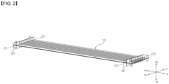
- a heat exchanger may include a tube panel 10.
- the tube panel 10 may be elongated in one direction.
- the tube panel 10 may have a plurality of channels 101 therein through which a refrigerant passes (see FIG. 3 ).
- the heat exchanger includes a header H.
- the header H may be provided in a pair and may be coupled to both ends of the tube panel 10.
- the header H may be elongated to a side.
- a plurality of tube panels 10 may be spaced apart from each other and arranged in the longitudinal direction of the header H.
- the header H is formed by combining a header case 30 and a header panel module 200 (see FIG. 9 ).
- a refrigerant can flow into any one of the pair of headers H.
- the refrigerant flowing inside can pass through the channels 101 of the tube panel 10.
- the refrigerant that has passed through the channels 101 can flow into the other one of the pair of headers H and then can be discharged out of the heat exchanger.
- Air can exchange heat with the refrigerant while passing through between a plurality of tube panels 10.
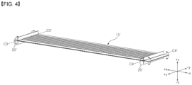
- the tube panel 10 may be elongated in the up-down direction.
- Header panels 10 may be formed in a pair at the upper end and lower end of the tube panel 10, respectively.
- the header panels 20 may be elongated in the left-right direction.
- the header panels 20 may be disposed perpendicular to the tube panel 10.
- the header panels 20 are formed by bending both ends of the tube panel 10.
- the header panels 20 may be formed by bending both ends of the first panel 11 and the second panel 12 in opposite directions.
- the first panel 11 and the second panel 12 may be bent perpendicular to the tube panel 10.
- the header panels 20 each may be divided into a header panel portion 21 formed by bending an end of the first panel 11 and a header panel portion 22 formed by bending an end of the second panel 12.
- the first tube panel 10a is formed by bonding a first panel 11a and a second panel 12a.
- the second tube panel 10b is formed by bonding a third panel 11b and a fourth panel 12b.
- the first panel 11a and the second panel 12a are the same as the first panel 11 and the second panel 12 described above, so they are not described.
- the third panel 11b and the fourth panel 12b are the same as the first panel 11 and the second panel 12 described above, so they are not described.
- the first header panel 20a and the second header panel 20b are overlapped and bonded to each other.
- the first header panel 20a and the second header panel 20b are overlapped and bonded between every first tube panel 10a and second tube panel 10.
- first header panels 20a except for the outermost first header panel 20a of the plurality of first header panels 20a may be bonded to two second header panels 20b.
- the other second header panels 20b except for the outermost second header panel 20b of the plurality of second header panels 20b may be bonded to two first header panels 20a.
- a refrigerant may flow into the header case 30 or may be discharged from the header case 30.
- the heat exchanger may include a pair of header cases 30. A refrigerant flowing in any one of the pair of header cases 30 may be discharged outside through the other one of the pair of header cases 30.
- a tube panel module 100 may be composed of a plurality of tube panels 10 disposed in parallel.
- the tube panel module 100 may include a plurality of first tube panels 10a and second tube panels 10b.
- a header panel module 200 may be formed at the upper end and the lower end of the tube panel module 100.
- the header panel module 200 may be elongated in the left-right direction.
- the header panel module 200 may be disposed perpendicular to the tube panel module 100.
- a first insertion groove 321 may be formed on both sides 32 of the header case 30. That is, the first insertion groove 321 may be formed on the left side 32 and the right side 32 of the header case 30.
- the first insertion grooves 32 may be recessed on both sides 32 of the header case 30 to face the space 31 of the header case 30.
- the first insertion grooves 32 may have a shape elongated in the front-rear direction.
- the insertion panels 201 may be inserted and coupled in the first insertion grooves 321.
- the header panel module 200 can cover the open one side of the case 30.
- the first insertion grooves 321 may be elongated rearward from the front end of the header case 30.
- the first insertion grooves 321 can guide insertion of the insertion panels 201.
- the insertion panels 201 can be inserted into the front ends of the first insertion grooves 321 and then guided rearward along the first insertion grooves 321.
- the front surface 34 of the header case 30 may be formed lower than the height of the first insertion grooves 321. Accordingly, when the insertion panels 201 are inserted into the front ends of the first insertion grooves 321 and then guided rearward, the header panel module 200 can move over the top of the front surface 34.
- the header case 30 may include a cap block 342 disposed on the front surface 34 of the header case.
- the cap block 342 may face the space 31 of the header case 30.
- the cap block 342 may be positioned in the same plane as the front surface 34 of the header case 30.
- the cap block 342 can cover the front of the header case 30 in cooperation with the front surface 34.
- the cap block 342 may be inserted in the front ends of the first insertion grooves 321. After the insertion panels 201 are inserted in the first insertion grooves 321, the cap block 342 may be inserted into the front ends of the first insertion grooves 321. The cap block 342 may come in contact with the header module panel 200 inserted in the first insertion grooves 321 and the front surface 34 of the header case.
- the cap block 342 may have protrusions 341 having a shape corresponding to the first insertion groove 321.
- the protrusions 341 may be formed in a pair at both sides of the cap block 342 and inserted in the first insertion grooves 321.
- a second insertion groove 331 may be formed on the rear surface 33 of the header case 30.
- the second insertion groove 331 may be recessed on the rear surface 33 of the header case 30 to face the space 31.
- the header panel module 200 may be inserted in the second insertion groove 331.
- a portion of the tube panel module 100 that is adjacent to the header panel module 200 may be inserted in the second insertion groove 331.
- the first tube panel 10a is formed by bonding a first panel 11a and a second panel 12a.
- the second tube panel 10b is formed by bonding a third panel 11b and the second panel 12b.
Landscapes
- Engineering & Computer Science (AREA)
- Mechanical Engineering (AREA)
- Physics & Mathematics (AREA)
- Thermal Sciences (AREA)
- General Engineering & Computer Science (AREA)
- Geometry (AREA)
- Heat-Exchange Devices With Radiators And Conduit Assemblies (AREA)
Claims (11)
- Wärmetauscher, der aufweist:ein Rohrplattenmodul (100), das sich in einer Aufwärts-Abwärts-Richtung erstreckt und mehrere erste Rohrplatten (10a) und zweite Rohrplatten (10b) aufweist, die abwechselnd in einer Links-Rechts-Richtung angeordnet sind;Verteilerplattenmodule (200), die jeweils an einem oberen Ende und einem unteren Ende des Rohrplattenmoduls (100) ausgebildet sind und sich in einer Links-Rechts-Richtung erstrecken; undein Verteilergehäuse (30), das eine offene Seite aufweist, einen Raum darin bereitstellt und an der einen Seite durch das Abdeckmodul abgedeckt ist, so dass die ersten Rohrplatten (10a) und die zweiten Rohrplatten (10b) mit dem Raum in Verbindung stehen,wobei die erste Rohrplatte (10a) durch Verbinden einer ersten Platte (11a) und einer zweiten Platte (12a) gebildet wird,die zweite Rohrplatte (10b) durch Verbinden einer dritten Platte (11b) und einer vierten Platte (12b) gebildet wird, unddas Verteilerplattenmodul (200) umfasst:eine erste Verteilerplatte (20a), die durch Biegen beider Enden der ersten Platte (11a) und der zweiten Platte (12a) in entgegengesetzte Richtungen gebildet wird; undeine zweite Verteilerplatte (20b), die durch Biegen beider Enden der dritten Platte (11b) und der vierten Platte (12b) in entgegengesetzte Richtungen gebildet und mit der ersten Verteilerplatte (20a) zwischen jeder ersten Rohrplatte (10a) und zweiten Rohrplatte (10b) verbunden ist,wobei die mehreren ersten Verteilerplatten (20a) in derselben Ebene angeordnet sind, die mehreren zweiten Verteilerplatten (20b) in derselben Ebene angeordnet und mit den Oberseiten der ersten Verteilerplatten verbunden sind,dadurch gekennzeichnet, dassdie mehreren zweiten Verteilerplatten (20b) über den ersten Verteilerplatten (20a) angeordnet sind,wobeidie erste Verteilerplatte (20a) und die zweite Verteilerplatte (20b) abwechselnd angeordnet sind und einander zwischen der ersten Rohrplatte (10a) und der zweiten Rohrplatte (10b) überlappen.
- Wärmetauscher nach Anspruch 1, wobei die erste Verteilerplatte (20a) senkrecht zur ersten Rohrplatte (10a) angeordnet ist, und
die zweite Verteilerplatte (20b) senkrecht zur zweiten Rohrplatte (10b) angeordnet ist. - Wärmetauscher nach Anspruch 1 oder 2, wobei die erste Verteilerplatte (20a) erste flache Abschnitte (202a) und erste Vertiefungen (203a) aufweist, die abwechselnd ausgebildet sind,die zweite Verteilerplatte (20b) zweite flache Abschnitte (202b) und zweite Vertiefungen (203b) aufweist, die abwechselnd ausgebildet sind, undder erste flache Abschnitt (202a) und der zweite flache Abschnitt (202b) miteinander in Kontakt stehen und die erste Vertiefung (203a) und die zweite Vertiefung (203b) an einem Abschnitt miteinander in Kontakt stehen, an dem die erste Verteilerplatte (20a) und die zweite Verteilerplatte (20b) miteinander verbunden sind.
- Wärmetauscher nach Anspruch 1, 2 oder 3, wobei die erste Verteilerplatte (20a) durch Biegen der beiden Enden der ersten Platte (11a) und der zweiten Platte (12a) gebildet wird, die flach sind, und
die zweite Verteilerplatte (20b) durch Biegen der beiden Enden der dritten Platte (11b) und der vierten Platte (12b) gebildet wird, die flach sind. - Wärmetauscher nach Anspruch 4, wobei das erste Rohrplatte (10a) und die zweite Rohrplatte (10b) jeweils einen Kanal (101) aufweisen, durch den ein Kältemittel fließt, und
die Kanäle (101) an der Außenseite der ersten Rohrplatte (10a) und der zweiten Rohrplatte (10b) durch Stanzen der ersten Verteilerplatte (20a) und der zweiten Verteilerplatte (20b) freigelegt wird. - Wärmetauscher nach einem der Ansprüche 1 bis 5, wobei die erste Verteilerplatte (20a) durch Einsetzen einer Vorrichtung zwischen die beiden Enden der ersten Platte (11a) und der zweiten Platte (12a) und anschließendes Öffnen der Enden zu beiden Seiten hin gebildet wird, und
die zweite Verteilerplatte (20b) durch Einsetzen einer Vorrichtung zwischen die beiden Enden der dritten Platte (11b) und der vierten Platte (12b) und anschließendes Öffnen der Enden zu beiden Seiten hin gebildet wird. - Wärmetauscher nach einem der Ansprüche 1 bis 6, wobei die Abschnitte, die an einem linken Ende und einem rechten Ende des Verteilerplattenmoduls (200) positioniert sind und links und rechts aus dem Rohrplattenmodul (100) herausragen, als Einsatzplatten (201) definiert sind,
das Verteilergehäuse (30) ferner erste Einsatznuten (321) aufweist, die auf einer linken Seite und einer rechten Seite des Verteilergehäuses (30) ausgespart sind, so dass sie dem Raum gegenüberliegen, und in die die Einsatzplatten (201) eingesetzt werden. - Wärmetauscher nach Anspruch 7, wobei die ersten Einsatznuten (321) sich von einem vorderen Ende des Verteilergehäuses (30) nach hinten erstrecken und das Einsetzen der Einsatzplatten (201) führen, und
eine Vorderfläche des Verteilergehäuses (30) niedriger als eine Höhe der ersten Einsatznuten (321) ausgebildet ist und das Verteilerplattenmodul (200) sich über eine Oberseite der vorderen Oberfläche bewegt. - Wärmetauscher nach Anspruch 8, wobei das Verteilergehäuse (30) einen Kappenblock (342) aufweist, der in die ersten Einsatznuten (321) eingesetzt ist und in Kontakt mit dem Verteilerplattenmodul (200) und der Vorderfläche des Verteilergehäuses (30) steht.
- Wärmetauscher nach Anspruch 9, wobei eine hintere Fläche des Verteilergehäuses (30) und der Kappenblock (342) eine zweite Einsatznut (331) aufweisen, die ausgespart ist, so dass sie dem Raum gegenüberliegt und in die das Verteilerplattenmodul (200) und ein Abschnitt des Rohrplattenmoduls (100) eingesetzt sind.
- Wärmetauscher nach Anspruch 10, wobei die zweite Einsatznut (331) aufweist:mehrere Rohrplattennuten (331a), die sich in der Aufwärts-Abwärts-Richtung erstrecken sind und in der Links-Rechts-Richtung angeordnet sind und in die die mehreren Rohrplatten (10a, 10b) eingesetzt sind; undeine Verteilerplattennut (331b), die sich in der Links-Rechts-Richtung erstreckt und in die das Verteilerplattenmodul (200) eingesetzt ist.
Applications Claiming Priority (1)
| Application Number | Priority Date | Filing Date | Title |
|---|---|---|---|
| KR1020200134404A KR102956462B1 (ko) | 2020-10-16 | 열교환기 및 열교환기 제조방법 |
Publications (2)
| Publication Number | Publication Date |
|---|---|
| EP3985342A1 EP3985342A1 (de) | 2022-04-20 |
| EP3985342B1 true EP3985342B1 (de) | 2024-07-03 |
Family
ID=78212037
Family Applications (1)
| Application Number | Title | Priority Date | Filing Date |
|---|---|---|---|
| EP21202822.9A Active EP3985342B1 (de) | 2020-10-16 | 2021-10-15 | Wärmetauscher |
Country Status (2)
| Country | Link |
|---|---|
| US (1) | US12111118B2 (de) |
| EP (1) | EP3985342B1 (de) |
Families Citing this family (2)
| Publication number | Priority date | Publication date | Assignee | Title |
|---|---|---|---|---|
| US12111118B2 (en) * | 2020-10-16 | 2024-10-08 | Lg Electronics Inc. | Heat exchanger and heat exchanger manufacturing method |
| KR102942940B1 (ko) * | 2023-02-20 | 2026-03-23 | 엘지전자 주식회사 | 열교환기 |
Family Cites Families (14)
| Publication number | Priority date | Publication date | Assignee | Title |
|---|---|---|---|---|
| US1950500A (en) * | 1932-04-19 | 1934-03-13 | Loprich | Radiator fin |
| EP0165788A3 (de) * | 1984-06-20 | 1986-04-23 | D. Mulock-Bentley And Associates (Proprietary) Limited | Wärmetauscher |
| JP2909745B2 (ja) * | 1989-03-31 | 1999-06-23 | 株式会社ゼクセル | 積層型エバポレータ |
| KR100644135B1 (ko) | 2005-11-14 | 2006-11-10 | 주식회사 두원공조 | 열교환기의 헤더 파이프 |
| KR200432601Y1 (ko) | 2006-07-10 | 2006-12-05 | 주식회사 고산 | 열교환기용 헤더파이프 |
| KR101447072B1 (ko) | 2008-09-08 | 2014-10-06 | 한라비스테온공조 주식회사 | 열교환기의 헤더 조립체 |
| KR20130064936A (ko) * | 2011-12-09 | 2013-06-19 | 현대자동차주식회사 | 차량용 열교환기 |
| KR20130065173A (ko) * | 2011-12-09 | 2013-06-19 | 현대자동차주식회사 | 차량용 열교환기 |
| KR20130065174A (ko) * | 2011-12-09 | 2013-06-19 | 현대자동차주식회사 | 차량용 열교환기 |
| KR102122256B1 (ko) * | 2013-12-24 | 2020-06-12 | 엘지전자 주식회사 | 열교환기 |
| JP2018155479A (ja) | 2017-03-16 | 2018-10-04 | ダイキン工業株式会社 | 伝熱管ユニットを有する熱交換器 |
| KR20190097632A (ko) | 2018-02-12 | 2019-08-21 | 엘지전자 주식회사 | 공기압 손실을 저감한 세경관 열교환기 |
| US12247792B2 (en) * | 2019-06-03 | 2025-03-11 | Hangzhou Sanhua Research Institute Co., Ltd. | Heat exchanger |
| US12111118B2 (en) * | 2020-10-16 | 2024-10-08 | Lg Electronics Inc. | Heat exchanger and heat exchanger manufacturing method |
-
2021
- 2021-10-14 US US17/501,116 patent/US12111118B2/en active Active
- 2021-10-15 EP EP21202822.9A patent/EP3985342B1/de active Active
Also Published As
| Publication number | Publication date |
|---|---|
| KR20220050575A (ko) | 2022-04-25 |
| EP3985342A1 (de) | 2022-04-20 |
| US12111118B2 (en) | 2024-10-08 |
| US20220120503A1 (en) | 2022-04-21 |
Similar Documents
| Publication | Publication Date | Title |
|---|---|---|
| US7775067B2 (en) | Heat exchanger header tank and heat exchanger comprising same | |
| EP1692449B1 (de) | Verdampfer und herstellungsverfahren dafür | |
| US6357519B1 (en) | Compound heat exchanger having two cores | |
| EP3985342B1 (de) | Wärmetauscher | |
| US20140196877A1 (en) | Tube for heat exchanger | |
| CN113939705B (zh) | 热交换器 | |
| US20060168812A1 (en) | Method of forming heat exchanger tubing and tubing formed thereby | |
| US6644392B2 (en) | Heat exchanger and a method of manufacturing a heat exchanger | |
| KR20060052945A (ko) | 열교환기 | |
| CN100541108C (zh) | 集管箱和具有该集管箱的热交换器 | |
| US9669455B2 (en) | Method for producing a heat exchanger and heat exchanger obtained by said method, swage and tube expansion device for implementing said method | |
| US6173765B1 (en) | Heat exchange having header tank | |
| WO2014041771A1 (ja) | 熱交換器 | |
| US20050224219A1 (en) | Heat exchanger unit, in particular for a motor vehicle and method for producing said unit | |
| US20050211425A1 (en) | Heat exchanger having an improved baffle | |
| CN1965209A (zh) | 热交换器 | |
| JP4448354B2 (ja) | 熱交換器 | |
| KR20180023184A (ko) | 일체형 라디에이터 및 이의 조립 방법 | |
| EP3985341B1 (de) | Wärmetauscher | |
| KR102956462B1 (ko) | 열교환기 및 열교환기 제조방법 | |
| JP2017101842A (ja) | 熱交換器 | |
| JP2008002723A (ja) | 一体型熱交換器 | |
| EP3372940A1 (de) | Wärmetauscher und verfahren zur herstellung einer versetzten streifenrippe für wärmetauscher | |
| JP2007278557A (ja) | 熱交換器 | |
| WO2020174037A1 (en) | Assembly method for a collector box for a heat exchanger |
Legal Events
| Date | Code | Title | Description |
|---|---|---|---|
| PUAI | Public reference made under article 153(3) epc to a published international application that has entered the european phase |
Free format text: ORIGINAL CODE: 0009012 |
|
| STAA | Information on the status of an ep patent application or granted ep patent |
Free format text: STATUS: REQUEST FOR EXAMINATION WAS MADE |
|
| 17P | Request for examination filed |
Effective date: 20211015 |
|
| AK | Designated contracting states |
Kind code of ref document: A1 Designated state(s): AL AT BE BG CH CY CZ DE DK EE ES FI FR GB GR HR HU IE IS IT LI LT LU LV MC MK MT NL NO PL PT RO RS SE SI SK SM TR |
|
| RBV | Designated contracting states (corrected) |
Designated state(s): AL AT BE BG CH CY CZ DE DK EE ES FI FR GB GR HR HU IE IS IT LI LT LU LV MC MK MT NL NO PL PT RO RS SE SI SK SM TR |
|
| STAA | Information on the status of an ep patent application or granted ep patent |
Free format text: STATUS: EXAMINATION IS IN PROGRESS |
|
| 17Q | First examination report despatched |
Effective date: 20230503 |
|
| GRAP | Despatch of communication of intention to grant a patent |
Free format text: ORIGINAL CODE: EPIDOSNIGR1 |
|
| STAA | Information on the status of an ep patent application or granted ep patent |
Free format text: STATUS: GRANT OF PATENT IS INTENDED |
|
| INTG | Intention to grant announced |
Effective date: 20240124 |
|
| GRAS | Grant fee paid |
Free format text: ORIGINAL CODE: EPIDOSNIGR3 |
|
| GRAA | (expected) grant |
Free format text: ORIGINAL CODE: 0009210 |
|
| STAA | Information on the status of an ep patent application or granted ep patent |
Free format text: STATUS: THE PATENT HAS BEEN GRANTED |
|
| RIN1 | Information on inventor provided before grant (corrected) |
Inventor name: LEE, HANCHOON Inventor name: KIM, HONGSEONG Inventor name: JUNG, SEUNGMO Inventor name: KIM, SUNGWOO |
|
| AK | Designated contracting states |
Kind code of ref document: B1 Designated state(s): AL AT BE BG CH CY CZ DE DK EE ES FI FR GB GR HR HU IE IS IT LI LT LU LV MC MK MT NL NO PL PT RO RS SE SI SK SM TR |
|
| REG | Reference to a national code |
Ref country code: CH Ref legal event code: EP |
|
| REG | Reference to a national code |
Ref country code: DE Ref legal event code: R096 Ref document number: 602021015079 Country of ref document: DE |
|
| REG | Reference to a national code |
Ref country code: LT Ref legal event code: MG9D |
|
| REG | Reference to a national code |
Ref country code: NL Ref legal event code: MP Effective date: 20240703 |
|
| PG25 | Lapsed in a contracting state [announced via postgrant information from national office to epo] |
Ref country code: PT Free format text: LAPSE BECAUSE OF FAILURE TO SUBMIT A TRANSLATION OF THE DESCRIPTION OR TO PAY THE FEE WITHIN THE PRESCRIBED TIME-LIMIT Effective date: 20241104 |
|
| REG | Reference to a national code |
Ref country code: AT Ref legal event code: MK05 Ref document number: 1700208 Country of ref document: AT Kind code of ref document: T Effective date: 20240703 |
|
| PG25 | Lapsed in a contracting state [announced via postgrant information from national office to epo] |
Ref country code: NL Free format text: LAPSE BECAUSE OF FAILURE TO SUBMIT A TRANSLATION OF THE DESCRIPTION OR TO PAY THE FEE WITHIN THE PRESCRIBED TIME-LIMIT Effective date: 20240703 |
|
| PG25 | Lapsed in a contracting state [announced via postgrant information from national office to epo] |
Ref country code: PT Free format text: LAPSE BECAUSE OF FAILURE TO SUBMIT A TRANSLATION OF THE DESCRIPTION OR TO PAY THE FEE WITHIN THE PRESCRIBED TIME-LIMIT Effective date: 20241104 Ref country code: NL Free format text: LAPSE BECAUSE OF FAILURE TO SUBMIT A TRANSLATION OF THE DESCRIPTION OR TO PAY THE FEE WITHIN THE PRESCRIBED TIME-LIMIT Effective date: 20240703 |
|
| PG25 | Lapsed in a contracting state [announced via postgrant information from national office to epo] |
Ref country code: NO Free format text: LAPSE BECAUSE OF FAILURE TO SUBMIT A TRANSLATION OF THE DESCRIPTION OR TO PAY THE FEE WITHIN THE PRESCRIBED TIME-LIMIT Effective date: 20241003 |
|
| PG25 | Lapsed in a contracting state [announced via postgrant information from national office to epo] |
Ref country code: FI Free format text: LAPSE BECAUSE OF FAILURE TO SUBMIT A TRANSLATION OF THE DESCRIPTION OR TO PAY THE FEE WITHIN THE PRESCRIBED TIME-LIMIT Effective date: 20240703 Ref country code: GR Free format text: LAPSE BECAUSE OF FAILURE TO SUBMIT A TRANSLATION OF THE DESCRIPTION OR TO PAY THE FEE WITHIN THE PRESCRIBED TIME-LIMIT Effective date: 20241004 Ref country code: PL Free format text: LAPSE BECAUSE OF FAILURE TO SUBMIT A TRANSLATION OF THE DESCRIPTION OR TO PAY THE FEE WITHIN THE PRESCRIBED TIME-LIMIT Effective date: 20240703 |
|
| PG25 | Lapsed in a contracting state [announced via postgrant information from national office to epo] |
Ref country code: BG Free format text: LAPSE BECAUSE OF FAILURE TO SUBMIT A TRANSLATION OF THE DESCRIPTION OR TO PAY THE FEE WITHIN THE PRESCRIBED TIME-LIMIT Effective date: 20240703 |
|
| PG25 | Lapsed in a contracting state [announced via postgrant information from national office to epo] |
Ref country code: LV Free format text: LAPSE BECAUSE OF FAILURE TO SUBMIT A TRANSLATION OF THE DESCRIPTION OR TO PAY THE FEE WITHIN THE PRESCRIBED TIME-LIMIT Effective date: 20240703 |
|
| PG25 | Lapsed in a contracting state [announced via postgrant information from national office to epo] |
Ref country code: IS Free format text: LAPSE BECAUSE OF FAILURE TO SUBMIT A TRANSLATION OF THE DESCRIPTION OR TO PAY THE FEE WITHIN THE PRESCRIBED TIME-LIMIT Effective date: 20241103 Ref country code: AT Free format text: LAPSE BECAUSE OF FAILURE TO SUBMIT A TRANSLATION OF THE DESCRIPTION OR TO PAY THE FEE WITHIN THE PRESCRIBED TIME-LIMIT Effective date: 20240703 |
|
| PG25 | Lapsed in a contracting state [announced via postgrant information from national office to epo] |
Ref country code: HR Free format text: LAPSE BECAUSE OF FAILURE TO SUBMIT A TRANSLATION OF THE DESCRIPTION OR TO PAY THE FEE WITHIN THE PRESCRIBED TIME-LIMIT Effective date: 20240703 Ref country code: CZ Free format text: LAPSE BECAUSE OF FAILURE TO SUBMIT A TRANSLATION OF THE DESCRIPTION OR TO PAY THE FEE WITHIN THE PRESCRIBED TIME-LIMIT Effective date: 20240703 |
|
| PG25 | Lapsed in a contracting state [announced via postgrant information from national office to epo] |
Ref country code: RS Free format text: LAPSE BECAUSE OF FAILURE TO SUBMIT A TRANSLATION OF THE DESCRIPTION OR TO PAY THE FEE WITHIN THE PRESCRIBED TIME-LIMIT Effective date: 20241003 Ref country code: ES Free format text: LAPSE BECAUSE OF FAILURE TO SUBMIT A TRANSLATION OF THE DESCRIPTION OR TO PAY THE FEE WITHIN THE PRESCRIBED TIME-LIMIT Effective date: 20240703 |
|
| PG25 | Lapsed in a contracting state [announced via postgrant information from national office to epo] |
Ref country code: RS Free format text: LAPSE BECAUSE OF FAILURE TO SUBMIT A TRANSLATION OF THE DESCRIPTION OR TO PAY THE FEE WITHIN THE PRESCRIBED TIME-LIMIT Effective date: 20241003 Ref country code: PL Free format text: LAPSE BECAUSE OF FAILURE TO SUBMIT A TRANSLATION OF THE DESCRIPTION OR TO PAY THE FEE WITHIN THE PRESCRIBED TIME-LIMIT Effective date: 20240703 Ref country code: NO Free format text: LAPSE BECAUSE OF FAILURE TO SUBMIT A TRANSLATION OF THE DESCRIPTION OR TO PAY THE FEE WITHIN THE PRESCRIBED TIME-LIMIT Effective date: 20241003 Ref country code: LV Free format text: LAPSE BECAUSE OF FAILURE TO SUBMIT A TRANSLATION OF THE DESCRIPTION OR TO PAY THE FEE WITHIN THE PRESCRIBED TIME-LIMIT Effective date: 20240703 Ref country code: IS Free format text: LAPSE BECAUSE OF FAILURE TO SUBMIT A TRANSLATION OF THE DESCRIPTION OR TO PAY THE FEE WITHIN THE PRESCRIBED TIME-LIMIT Effective date: 20241103 Ref country code: HR Free format text: LAPSE BECAUSE OF FAILURE TO SUBMIT A TRANSLATION OF THE DESCRIPTION OR TO PAY THE FEE WITHIN THE PRESCRIBED TIME-LIMIT Effective date: 20240703 Ref country code: GR Free format text: LAPSE BECAUSE OF FAILURE TO SUBMIT A TRANSLATION OF THE DESCRIPTION OR TO PAY THE FEE WITHIN THE PRESCRIBED TIME-LIMIT Effective date: 20241004 Ref country code: FI Free format text: LAPSE BECAUSE OF FAILURE TO SUBMIT A TRANSLATION OF THE DESCRIPTION OR TO PAY THE FEE WITHIN THE PRESCRIBED TIME-LIMIT Effective date: 20240703 Ref country code: ES Free format text: LAPSE BECAUSE OF FAILURE TO SUBMIT A TRANSLATION OF THE DESCRIPTION OR TO PAY THE FEE WITHIN THE PRESCRIBED TIME-LIMIT Effective date: 20240703 Ref country code: CZ Free format text: LAPSE BECAUSE OF FAILURE TO SUBMIT A TRANSLATION OF THE DESCRIPTION OR TO PAY THE FEE WITHIN THE PRESCRIBED TIME-LIMIT Effective date: 20240703 Ref country code: BG Free format text: LAPSE BECAUSE OF FAILURE TO SUBMIT A TRANSLATION OF THE DESCRIPTION OR TO PAY THE FEE WITHIN THE PRESCRIBED TIME-LIMIT Effective date: 20240703 Ref country code: AT Free format text: LAPSE BECAUSE OF FAILURE TO SUBMIT A TRANSLATION OF THE DESCRIPTION OR TO PAY THE FEE WITHIN THE PRESCRIBED TIME-LIMIT Effective date: 20240703 |
|
| REG | Reference to a national code |
Ref country code: DE Ref legal event code: R097 Ref document number: 602021015079 Country of ref document: DE |
|
| PG25 | Lapsed in a contracting state [announced via postgrant information from national office to epo] |
Ref country code: SM Free format text: LAPSE BECAUSE OF FAILURE TO SUBMIT A TRANSLATION OF THE DESCRIPTION OR TO PAY THE FEE WITHIN THE PRESCRIBED TIME-LIMIT Effective date: 20240703 Ref country code: DK Free format text: LAPSE BECAUSE OF FAILURE TO SUBMIT A TRANSLATION OF THE DESCRIPTION OR TO PAY THE FEE WITHIN THE PRESCRIBED TIME-LIMIT Effective date: 20240703 Ref country code: RO Free format text: LAPSE BECAUSE OF FAILURE TO SUBMIT A TRANSLATION OF THE DESCRIPTION OR TO PAY THE FEE WITHIN THE PRESCRIBED TIME-LIMIT Effective date: 20240703 |
|
| PG25 | Lapsed in a contracting state [announced via postgrant information from national office to epo] |
Ref country code: EE Free format text: LAPSE BECAUSE OF FAILURE TO SUBMIT A TRANSLATION OF THE DESCRIPTION OR TO PAY THE FEE WITHIN THE PRESCRIBED TIME-LIMIT Effective date: 20240703 |
|
| PG25 | Lapsed in a contracting state [announced via postgrant information from national office to epo] |
Ref country code: IT Free format text: LAPSE BECAUSE OF FAILURE TO SUBMIT A TRANSLATION OF THE DESCRIPTION OR TO PAY THE FEE WITHIN THE PRESCRIBED TIME-LIMIT Effective date: 20240703 Ref country code: SK Free format text: LAPSE BECAUSE OF FAILURE TO SUBMIT A TRANSLATION OF THE DESCRIPTION OR TO PAY THE FEE WITHIN THE PRESCRIBED TIME-LIMIT Effective date: 20240703 |
|
| PLBE | No opposition filed within time limit |
Free format text: ORIGINAL CODE: 0009261 |
|
| STAA | Information on the status of an ep patent application or granted ep patent |
Free format text: STATUS: NO OPPOSITION FILED WITHIN TIME LIMIT |
|
| REG | Reference to a national code |
Ref country code: CH Ref legal event code: PL |
|
| 26N | No opposition filed |
Effective date: 20250404 |
|
| PG25 | Lapsed in a contracting state [announced via postgrant information from national office to epo] |
Ref country code: MC Free format text: LAPSE BECAUSE OF FAILURE TO SUBMIT A TRANSLATION OF THE DESCRIPTION OR TO PAY THE FEE WITHIN THE PRESCRIBED TIME-LIMIT Effective date: 20240703 |
|
| PG25 | Lapsed in a contracting state [announced via postgrant information from national office to epo] |
Ref country code: LU Free format text: LAPSE BECAUSE OF NON-PAYMENT OF DUE FEES Effective date: 20241015 Ref country code: BE Free format text: LAPSE BECAUSE OF NON-PAYMENT OF DUE FEES Effective date: 20241031 |
|
| PG25 | Lapsed in a contracting state [announced via postgrant information from national office to epo] |
Ref country code: FR Free format text: LAPSE BECAUSE OF NON-PAYMENT OF DUE FEES Effective date: 20241031 |
|
| PG25 | Lapsed in a contracting state [announced via postgrant information from national office to epo] |
Ref country code: CH Free format text: LAPSE BECAUSE OF NON-PAYMENT OF DUE FEES Effective date: 20241031 |
|
| REG | Reference to a national code |
Ref country code: BE Ref legal event code: MM Effective date: 20241031 |
|
| PG25 | Lapsed in a contracting state [announced via postgrant information from national office to epo] |
Ref country code: SE Free format text: LAPSE BECAUSE OF FAILURE TO SUBMIT A TRANSLATION OF THE DESCRIPTION OR TO PAY THE FEE WITHIN THE PRESCRIBED TIME-LIMIT Effective date: 20240703 |
|
| PG25 | Lapsed in a contracting state [announced via postgrant information from national office to epo] |
Ref country code: IE Free format text: LAPSE BECAUSE OF NON-PAYMENT OF DUE FEES Effective date: 20241015 |
|
| PGFP | Annual fee paid to national office [announced via postgrant information from national office to epo] |
Ref country code: DE Payment date: 20250908 Year of fee payment: 5 |
|
| PG25 | Lapsed in a contracting state [announced via postgrant information from national office to epo] |
Ref country code: CY Free format text: LAPSE BECAUSE OF FAILURE TO SUBMIT A TRANSLATION OF THE DESCRIPTION OR TO PAY THE FEE WITHIN THE PRESCRIBED TIME-LIMIT; INVALID AB INITIO Effective date: 20211015 |
|
| PG25 | Lapsed in a contracting state [announced via postgrant information from national office to epo] |
Ref country code: HU Free format text: LAPSE BECAUSE OF FAILURE TO SUBMIT A TRANSLATION OF THE DESCRIPTION OR TO PAY THE FEE WITHIN THE PRESCRIBED TIME-LIMIT; INVALID AB INITIO Effective date: 20211015 |