EP3985363A1 - Balance pourvue d'une bande transporteuse et corps de bande transporteuse - Google Patents
Balance pourvue d'une bande transporteuse et corps de bande transporteuse Download PDFInfo
- Publication number
- EP3985363A1 EP3985363A1 EP20202423.8A EP20202423A EP3985363A1 EP 3985363 A1 EP3985363 A1 EP 3985363A1 EP 20202423 A EP20202423 A EP 20202423A EP 3985363 A1 EP3985363 A1 EP 3985363A1
- Authority
- EP
- European Patent Office
- Prior art keywords
- conveyor belt
- roller bearings
- belt
- counter
- cross brace
- Prior art date
- Legal status (The legal status is an assumption and is not a legal conclusion. Google has not performed a legal analysis and makes no representation as to the accuracy of the status listed.)
- Granted
Links
Images

Classifications
-
- G—PHYSICS
- G01—MEASURING; TESTING
- G01G—WEIGHING
- G01G11/00—Apparatus for weighing a continuous stream of material during flow; Conveyor belt weighers
- G01G11/003—Details; specially adapted accessories
-
- G—PHYSICS
- G01—MEASURING; TESTING
- G01G—WEIGHING
- G01G11/00—Apparatus for weighing a continuous stream of material during flow; Conveyor belt weighers
-
- B—PERFORMING OPERATIONS; TRANSPORTING
- B65—CONVEYING; PACKING; STORING; HANDLING THIN OR FILAMENTARY MATERIAL
- B65G—TRANSPORT OR STORAGE DEVICES, e.g. CONVEYORS FOR LOADING OR TIPPING, SHOP CONVEYOR SYSTEMS OR PNEUMATIC TUBE CONVEYORS
- B65G15/00—Conveyors having endless load-conveying surfaces, i.e. belts and like continuous members, to which tractive effort is transmitted by means other than endless driving elements of similar configuration
- B65G15/60—Arrangements for supporting or guiding belts, e.g. by fluid jets
-
- B—PERFORMING OPERATIONS; TRANSPORTING
- B65—CONVEYING; PACKING; STORING; HANDLING THIN OR FILAMENTARY MATERIAL
- B65G—TRANSPORT OR STORAGE DEVICES, e.g. CONVEYORS FOR LOADING OR TIPPING, SHOP CONVEYOR SYSTEMS OR PNEUMATIC TUBE CONVEYORS
- B65G39/00—Rollers, e.g. drive rollers, or arrangements thereof incorporated in roller-ways or other types of mechanical conveyors
- B65G39/10—Arrangements of rollers
- B65G39/12—Arrangements of rollers mounted on framework
-
- G—PHYSICS
- G01—MEASURING; TESTING
- G01G—WEIGHING
- G01G19/00—Weighing apparatus or methods adapted for special purposes not provided for in the preceding groups
- G01G19/02—Weighing apparatus or methods adapted for special purposes not provided for in the preceding groups for weighing wheeled or rolling bodies, e.g. vehicles
- G01G19/03—Weighing apparatus or methods adapted for special purposes not provided for in the preceding groups for weighing wheeled or rolling bodies, e.g. vehicles for weighing during motion
-
- G—PHYSICS
- G01—MEASURING; TESTING
- G01G—WEIGHING
- G01G23/00—Auxiliary devices for weighing apparatus
- G01G23/06—Means for damping oscillations, e.g. of weigh beams
- G01G23/12—Means for damping oscillations, e.g. of weigh beams specially adapted for preventing oscillations due to movement of the load
Definitions
- the present invention relates to a conveyor belt for transporting piece goods, in particular for a conveyor belt scale for transporting and weighing piece goods, in particular weighing goods, which has a conveyor belt body with an upper side, an underside and a length extending in the transport direction of the piece goods and, during operation of the conveyor belt includes a conveyor belt circulating around the belt body.
- the EP1427999B1 shows a conveyor belt for a conveyor scale for weighing individual food items.
- a mechanism is proposed with which the tension of a conveyor belt of the conveyor belt is optimally maintained.
- the EP0592349A1 show a conveyor belt for a conveyor scale for weighing individual objects.
- the tension of a conveyor belt of the conveyor belt is maintained with a pivotable roller.
- the object of the invention is to provide a conveyor belt of the type mentioned at the outset, which enables the conveyor belt to run optimally smoothly at high speeds and, when used in conjunction with a conveyor belt scale, to determine the weight with great accuracy.
- a conveyor belt for transporting piece goods is proposed.
- the conveyor belt is in particular around a conveyor belt scale.
- the conveyor belt comprises a belt body with an upper side, an underside and a length extending in the direction of transport of the item.
- the conveyor belt includes a conveyor belt that circulates around the belt body when the conveyor belt is in operation.
- a belt guide device is fitted on the underside of the belt body between the belt body and the conveyor belt.
- the strip guiding device comprises at least two roller bearings.
- the inner rings of the roller bearings are each mounted on an axle.
- the axles for the roller bearings are a common axle.
- at least two roller bearings are mounted on separate axles, ie the inner rings of the roller bearings are each mounted on a separate axle.
- the axes are parallel to each other and stationary in relation to the body of the belt. Stationary in this context is not to be understood as meaning that the axes would not be rotatable. Rather, the position of the axes in relation to the belt body is determined.
- the outer rings of the roller bearings are in direct contact with the conveyor belt.
- the conveyor belt includes a belt guide device that has roller bearings, with the roller bearings being provided for guiding the belt.
- the conveyor belt runs over a front and a rear transport roller. On the way between the front and rear transport roller, the conveyor belt is supported and tensioned by the roller bearings. Rolling bearings have the advantage that they do not have to be aligned or balanced.
- the inner ring and outer ring of a rolling bearing are precisely aligned with one another.
- a smoother running of the conveyor belt is achieved in comparison to a belt guide device that tensions the conveyor belt with a transport roller.
- a transport roller for tensioning the transport belt would have to be aligned. Any tolerance in the alignment of the transport roller would have a direct negative effect on the smooth running of the conveyor belt and thus on the accuracy of the affect weight determination.
- the conveyor belt also runs unsteadily over a belt guide device, which consists only of a deflector plate. Furthermore, the conveyor belt would drag over the deflector plate and wear out more quickly.
- the roller bearings for supporting the conveyor belt offer a surprisingly simple and effective way of avoiding the disadvantages of a conveyor roller or a deflector plate.
- the roller bearings are very narrow compared to the width of the conveyor belt and only support the conveyor belt at certain points. Due to the fact that the conveyor belt is only selectively supported in the direction transverse to the direction of transport with the outer rings of the roller bearings and the parallel arrangement of the axes of the roller bearings, manual alignment of the belt guide device is not necessary.
- the roller bearings do not have to be balanced in a separate step during assembly. Since the outer rings of roller bearings are hardened, the conveyor belt can run directly over the outer rings of the roller bearings without wearing out the roller bearings.
- the tape guide device consists of a cross brace.
- the cross brace is attached to the underside of the belt body, in particular at least essentially in the middle.
- the transverse strut extends transversely, in particular perpendicularly to the transport direction, over a large part of the width of the belt body.
- the cross brace serves to hold the roller bearings, which guide the conveyor belt through direct contact with the conveyor belt.
- the roller bearings support the conveyor belt at several points distributed across the width of the conveyor belt. In most cases, the width of the conveyor belt is the same as or slightly smaller than the width of the belt body.
- the belt guide device, whose cross brace supports the roller bearings therefore has a width which is the same as or only slightly smaller than the width of the conveyor belt.
- the cross brace extends over a large part of the width of the belt body. In one embodiment, the cross brace extends over at least 80% of the width of the belt body.
- roller bearings are attached to the cross brace of the belt guide device with counter-holders.
- the cross strut comprises bevels in areas that are intended to accommodate roller bearings.
- the folds extend along the length of the cross brace. This indicates the direction of the folds. This should not necessarily be understood to mean that the folds extend over the entire width of the cross brace.
- the folds create a fold in the cross brace.
- a V-shape is created. This V-shape, which is easy to produce thanks to the folds, together with the counter-holders, ensures that the axes and therefore the roller bearings are automatically aligned in relation to the conveyor belt.
- the cross brace includes a continuous fold that extends over the entire length of the cross brace. This creates a V-shape to create areas intended to accommodate rolling bearings. This has the advantage that all roller bearings have the same height, since the axles of the roller bearings rest in the V-shape formed by the fold. In the case of axles and roller bearings of the same type, the outer surfaces of the outer rings of the roller bearings are at the same height and thus provide optimal guidance for the conveyor belt.
- the axles on which the inner rings of the roller bearings are fitted are held with counter-holders in a V-shape of the cross brace formed by the folds. This means that the axles are held in place by means of the V-shaped cross brace and the counterholds between the cross brace and counterhold.
- the interaction of the folds in the cross brace and the Counterholders mean that the axes are aligned perpendicular to the direction of transport during assembly. A separate alignment step is not necessary.
- the counter-holders each include two stops that limit the position of an axis in its axial direction. This means that the axles cannot slip out of the space between the cross brace and the counter-holder in the axial direction.
- the cross brace is in the form of a channel.
- a V-shape is formed centrally along the axis of the trough. This V-shape is formed by the folds of the cross brace.
- the inner angle of the V-shape is an obtuse angle, in particular an angle between 135° and 170°, in particular between 150° and 170°.
- the lateral ends of the channel-shaped cross strut have further folds and fastening openings.
- the cross brace is screwed to the belt body at the fastening openings.
- the lateral ends of the channel-shaped cross strut have further folds, with which the cross strut is riveted to the belt body. The other folds extend along the axis of the cross brace.
- the lateral ends refer to the lateral limits of the trough-shaped cross-brace and not to the axial ends of the trough-shaped cross-brace.
- the roller bearings are ball bearings or roller bearings.
- Ball bearings or roller bearings are readily available and inexpensive off-the-shelf components that have their inner and outer rings aligned. Thus, a separate alignment of the guides for the conveyor belt, which are formed by the outer rings of the ball bearings or roller bearings, is not necessary.
- the cross brace is formed from a bent metal sheet.
- the axes on which the Bearings are attached are attached to the side facing the belt body on the cross brace.
- the cross brace includes recesses through which the roller bearings partially protrude through the cross brace.
- the conveyor belt at least partially touches that part of the roller bearing that protrudes through the recess in the cross brace.
- the conveyor belt is selectively supported by the roller bearings and runs over part of the surface of the outer rings of the roller bearings. Due to the rotating movement of the conveyor belt and the contact of the outer rings of the roller bearings with the conveyor belt, the roller bearings rotate at a speed proportional to the conveyor belt.
- each counter-holder consists of a V-shaped metal sheet.
- the sheet metal is folded at its ends.
- the sheet metal has a recess through which the roller bearings partially protrude.
- the counter-holders are connected to the cross brace, in particular screwed or riveted.
- the course of the V-shape of the cross strut in the area in which a roller bearing is attached to the cross strut with the counter-holder is parallel to the course of the bent ends of a counter-holder. It is thus possible to screw or rivet the counter-holder to the cross brace.
- the recesses for the roller bearings in the cross brace and the recesses for the roller bearings in the counter brackets are aligned with each other.
- guide knobs which are arranged at the level of the inner ring of the roller bearing, protrude into the recess of the counter-holder from both sides. In this way, the roller bearing is laterally supported by the guide knobs. If the inner ring of the roller bearing is simply pushed onto the axle without forming a fixed connection, the roller bearing is held in its axial position by the guide knobs. the Axle can be moved in the axial direction as far as the stops allow. This means that there is no need for a fixed connection between the axle and the roller bearing, which simplifies production considerably.
- the invention also relates to a conveyor belt scale with a scale unit with at least one load cell and a conveyor belt placed on the scale unit according to the above description.
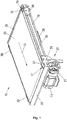
- This in 1 Conveyor belt shown is part of a conveyor belt scale, for example a checkweigher or a price labeller, on a scale unit with at least a load cell, in particular up to four load cells, which is attached to the conveyor belt scale.
- the conveyor belt shown is then a weighing belt 11.
- the weighing belt 11 is usually connected between a feed belt and a discharge belt, which in a special embodiment can also have the features of the weighing belt 11 according to the invention.
- piece goods or goods to be weighed can be transported over the weighing unit in order to determine the weight of the respective piece goods. The weight is usually determined during the further transport of the respective general cargo.
- the transport process can also be stopped to determine the weight.
- the weighing belt 11, which transports the piece goods in a transport direction 13, comprises a belt body 15, in particular made of aluminum, which is arranged between a first transport roller 17, which is designed as a drive roller, and a second transport roller 19, which is designed as an idler roller.
- the first transport roller 17 and the second transport roller 19 are in 1 largely covered by other components of the weighing belt 11, which will be discussed in more detail below.
- the two transport rollers 17, 19 are each rotatably mounted in two holders 29, which protrude from the belt body 15 on both sides of the belt body 15 in the transport direction 13 and counter to the transport direction 13, respectively.
- the first transport roller 17 is driven via a belt drive 21 by an electric motor 23 which is fixedly attached to the belt body 15 via a holding device 27 .
- the weighing belt 11 comprises a conveyor belt 25 designed as an endless belt, which runs around the belt body 15 and the two transport rollers 17, 19 when the weighing belt 11 is in operation. Furthermore, the weighing belt 11 comprises four cover plates 31, which are arranged to the left and right of the two transport rollers 17, 19, with only the two in 1 front cover plates 31 with a Reference numerals are provided. In addition, a protective strip 33 attached to the belt body 15 is provided for the conveyor belt 25 on the inlet and outlet sides, via which the weighing belt 11 and a feed belt that is configured appropriately at least on the outlet side and a discharge belt that is configured accordingly at least on the input side can be lined up end to end.
- the weighing belt 11 has a cover plate 35, in particular made of metal, which is arranged between the top of the belt body 15 and the upper run of the conveyor belt 25, so that the upper run of the conveyor belt 25 rests on the cover plate 35.
- the cover plate 35 extends in the transport direction 13 over the entire length of the belt body 15 and protrudes on both sides under the upper run of the transport belt 25 .
- a belt guide device with a cross brace 39, which extends transversely, in particular perpendicularly, to the transport direction 13 over a large part of the width or over the entire width of the belt body 15.
- the belt guide device ensures that the lower run of the conveyor belt 25 runs smoothly.
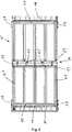
- the belt body 15 consists of a profile arrangement of several profiles 41, 43.
- the profile arrangement comprises five profiles 41 extending in the transport direction 13 of the unit load and two profiles 41 extending transversely to the transport direction 13 of the unit load extending profiles 43.
- the profiles 41, 43 are each extruded profiles, in particular made of aluminum.
- the belt body 15 forms the frame of the conveyor belt, in particular the weighing belt 11 of a transport scale, and holds other components of the weighing belt 11, in particular the transport rollers 17, 19, which are fastened to the belt body 15 by means of brackets 29.
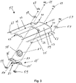
- a belt guide device 51 consists of a transverse strut 39 which extends transversely, in particular perpendicularly, to the transport direction 13 and is attached at least essentially centrally with screws 53 to the underside of the belt body 15 .
- the belt guide device 51 includes roller bearings 55 which are attached to the crossbar 39 on the side facing the belt body 15 and protrude at least partially through the crossbar 39 in the direction of the lower strand of the conveyor belt.
- FIG. 12 shows an exploded view of the tape guide assembly 51.
- the cross brace 39 is partially shown.
- the transverse strut 39 is formed by a bent metal sheet, so that a fold is created centrally along the longitudinal axis of the transverse strut 39 by a central fold 71, which fold forms a V-shape.
- the inner angle of the V-shape is an obtuse angle, in particular an angle between 135° and 170°, in particular between 150° and 170°.
- the transverse strut 39 forms the shape of a channel by means of a further fold 77 on both sides of the fold.
- Two fastening rails 75 are formed on the outer sides of the cross brace 39 by a further fold 73 in each case.
- the fastening rails 75 are horizontal and comprise fastening openings 63 with which the cross brace 39 is fastened to the belt body 15 by means of screws 53 and washers 57 , in particular to the profiles 41 arranged parallel to the transport direction 13 .
- Recesses 67 are provided along the longitudinal direction of the cross brace 39 and are located in the area of the fold formed by the central fold 71 .
- the recesses 67 have a rectangular, elongated shape, the long side of which is oriented along the transport direction 13 . Through the recesses 67, the roller bearings 55 protrude partially through the cross brace 39.
- a plurality of recesses 67 are provided for a plurality of roller bearings 55, which are arranged in particular at regular intervals along the longitudinal direction of the cross brace 39.
- the roller bearings 55 are commercially available roller bearings, in particular ball bearings or roller bearings with an inner ring and an outer ring, the inner ring and the outer ring being arranged such that they can be moved in relation to one another via a bearing arrangement, that is to say they can be rotated in relation to one another.
- the inner ring of the roller bearing is slipped onto an axle 61 .
- the roller bearing 55 is mounted together with the axis on the inside of the cross brace 39, that is inside the channel of the cross brace 39. This side is the side facing the belt body 15 .
- the axis 61 is oriented along the fold formed by the central flange 71 and is supported in this fold in its radial direction.
- the roller bearing and the axle 61 are fixed using a counter-holder 65 .
- the counter-holder 65 is fastened with screws 69 and nuts 59 in the area of the recess 67 on the side of the cross brace 39 facing the belt body 15 .
- the counter-holder 85 consists of a V-shaped sheet metal.
- the V shape is formed by a central bevel 81 .
- the ends of the metal sheet are bent and form fastening lugs 85 which run parallel to the V-shape of the cross brace 39.
- the counter-holder 65 is attached to the cross brace 39 with screws 69 and nuts 59 by means of the fastening straps 85 .
- the counter-holder 65 includes a recess 87 through which the roller bearing 55 partially protrudes.
- the counter-holder 65 includes a stop 83 on each side, which limits an axial displacement of the axis 61 .
- a section of the tape guide device 51 is shown.
- the roller bearings 55 are attached to the cross brace 39 by means of the counter holder 65 .
- the view shows the Tape guide device 51 from the side facing the belt body 15 .
- figure 5 a side view of the conveyor belt in the area of the belt guide device is shown.
- the conveyor belt is not shown for the sake of clarity.
- figure 5 shows how the cross brace 39 is screwed to the profile with screws 53 and washers 57 at the fastening openings of the fastening rails.
- the axis 61 on which the inner ring of the roller bearing 55 is mounted lies in the V-shape of the crossbar 39 formed by the central fold.
- the counter-holder 65 which forms a V-shape in the opposite direction to the transverse strut 39 by means of a bevel 81, is screwed to its fastening lugs 85 with the transverse strut 39 by means of screws 69 and nuts 59.
- the counter-holder 65 includes a stop 83.
- a cover plate 35 is attached, over which the conveyor belt (not shown) slides.
- the roller bearing 55 protrudes through the recess through the cross brace 39 and below the cross brace 39, on the side facing away from the profile 41, forms a support for the circulating conveyor belt.
- the circulating conveyor belt is supported by part of the outside of the outer ring of the roller bearing 55 .
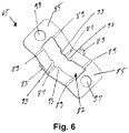
- the counter-holder 65 for mounting a roller bearing on a cross brace of the belt guide device.
- the counter-holder 65 is a bent sheet metal part that forms a V-shape by means of a central fold 81 .
- a further fold 89 towards each end forms a fastening lug 85.
- the fastening lugs 85 run parallel to the V-shape of the cross brace to which the counter-holder 65 is screwed.
- the fastening lugs 85 have a bore for screwing the counter-holder 65 to the cross brace.
- the V-shape of the counter-bracket 65 and the V-shape of the cross brace form a cavity in which an axle carrying a roller bearing can be accommodated. Since the V-shape of the cross brace 39 and the V-shape of the counter-holder 65 can have different angles, the cavity does not have to have a right-angled cross-section.
- the counter-holder comprises a recess 87 through which the roller bearing, which is mounted on an axle, protrudes.
- Guide knobs 93 protrude from both sides into the recess 87 and are arranged at the level of the inner ring of the roller bearing and touch the inner rings of the roller bearing. This prevents the roller bearing from slipping along the axis within the recess.
Landscapes
- Physics & Mathematics (AREA)
- General Physics & Mathematics (AREA)
- Engineering & Computer Science (AREA)
- Mechanical Engineering (AREA)
- Structure Of Belt Conveyors (AREA)
Priority Applications (3)
| Application Number | Priority Date | Filing Date | Title |
|---|---|---|---|
| EP23000180.2A EP4332024B1 (fr) | 2020-10-16 | 2020-10-16 | Balance à bande transporteuse avec bande transporteuse et corps de bande transporteuse |
| EP20202423.8A EP3985363B1 (fr) | 2020-10-16 | 2020-10-16 | Balance pourvue d'une bande transporteuse et corps de bande transporteuse |
| US17/497,985 US11604090B2 (en) | 2020-10-16 | 2021-10-11 | Belt conveyor scale including a belt conveyor as well as belt conveyor frame |
Applications Claiming Priority (1)
| Application Number | Priority Date | Filing Date | Title |
|---|---|---|---|
| EP20202423.8A EP3985363B1 (fr) | 2020-10-16 | 2020-10-16 | Balance pourvue d'une bande transporteuse et corps de bande transporteuse |
Related Child Applications (1)
| Application Number | Title | Priority Date | Filing Date |
|---|---|---|---|
| EP23000180.2A Division EP4332024B1 (fr) | 2020-10-16 | 2020-10-16 | Balance à bande transporteuse avec bande transporteuse et corps de bande transporteuse |
Publications (2)
| Publication Number | Publication Date |
|---|---|
| EP3985363A1 true EP3985363A1 (fr) | 2022-04-20 |
| EP3985363B1 EP3985363B1 (fr) | 2023-12-27 |
Family
ID=73013167
Family Applications (2)
| Application Number | Title | Priority Date | Filing Date |
|---|---|---|---|
| EP23000180.2A Active EP4332024B1 (fr) | 2020-10-16 | 2020-10-16 | Balance à bande transporteuse avec bande transporteuse et corps de bande transporteuse |
| EP20202423.8A Active EP3985363B1 (fr) | 2020-10-16 | 2020-10-16 | Balance pourvue d'une bande transporteuse et corps de bande transporteuse |
Family Applications Before (1)
| Application Number | Title | Priority Date | Filing Date |
|---|---|---|---|
| EP23000180.2A Active EP4332024B1 (fr) | 2020-10-16 | 2020-10-16 | Balance à bande transporteuse avec bande transporteuse et corps de bande transporteuse |
Country Status (2)
| Country | Link |
|---|---|
| US (1) | US11604090B2 (fr) |
| EP (2) | EP4332024B1 (fr) |
Families Citing this family (1)
| Publication number | Priority date | Publication date | Assignee | Title |
|---|---|---|---|---|
| CN117232629B (zh) * | 2023-03-10 | 2024-05-14 | 中山精量衡器制造有限公司 | 一种物流称重的通用称重装置 |
Citations (5)
| Publication number | Priority date | Publication date | Assignee | Title |
|---|---|---|---|---|
| EP0592349A1 (fr) | 1992-10-05 | 1994-04-13 | Jesma-Matador A/S | Dispositif pour pesage continu sur bande transporteuse |
| EP1427999B1 (fr) | 2001-08-03 | 2006-11-02 | Marel Hf. | Appareil et procede permettant de commander la tension de courroie d'une bascule a courroie |
| DE102007032270A1 (de) * | 2007-07-11 | 2009-01-15 | Mettler-Toledo Garvens Gmbh | Vorrichtung zum Prüfen von Produkten und Prüfverfahren |
| CN1915771B (zh) * | 2002-02-05 | 2010-10-06 | 株式会社石田 | X射线检查装置 |
| CN203624355U (zh) * | 2013-10-31 | 2014-06-04 | 徐义祥 | 一种称重传送机 |
Family Cites Families (2)
| Publication number | Priority date | Publication date | Assignee | Title |
|---|---|---|---|---|
| JPS5172463A (en) * | 1974-12-20 | 1976-06-23 | Kubota Ltd | Konbeya sukeeruniokeru juryosekisansochi |
| US11192723B2 (en) * | 2017-12-13 | 2021-12-07 | Laitram, L.L.C. | Hygienic hollow frame assembly |
-
2020
- 2020-10-16 EP EP23000180.2A patent/EP4332024B1/fr active Active
- 2020-10-16 EP EP20202423.8A patent/EP3985363B1/fr active Active
-
2021
- 2021-10-11 US US17/497,985 patent/US11604090B2/en active Active
Patent Citations (5)
| Publication number | Priority date | Publication date | Assignee | Title |
|---|---|---|---|---|
| EP0592349A1 (fr) | 1992-10-05 | 1994-04-13 | Jesma-Matador A/S | Dispositif pour pesage continu sur bande transporteuse |
| EP1427999B1 (fr) | 2001-08-03 | 2006-11-02 | Marel Hf. | Appareil et procede permettant de commander la tension de courroie d'une bascule a courroie |
| CN1915771B (zh) * | 2002-02-05 | 2010-10-06 | 株式会社石田 | X射线检查装置 |
| DE102007032270A1 (de) * | 2007-07-11 | 2009-01-15 | Mettler-Toledo Garvens Gmbh | Vorrichtung zum Prüfen von Produkten und Prüfverfahren |
| CN203624355U (zh) * | 2013-10-31 | 2014-06-04 | 徐义祥 | 一种称重传送机 |
Also Published As
| Publication number | Publication date |
|---|---|
| EP4332024B1 (fr) | 2024-12-04 |
| EP3985363B1 (fr) | 2023-12-27 |
| US20220120603A1 (en) | 2022-04-21 |
| US11604090B2 (en) | 2023-03-14 |
| EP4332024A3 (fr) | 2024-05-29 |
| EP4332024A2 (fr) | 2024-03-06 |
Similar Documents
| Publication | Publication Date | Title |
|---|---|---|
| DE102013203457B4 (de) | Gestell einer Wäge-Fördervorrichtung | |
| WO2021151433A1 (fr) | Convoyeur à bande modulaire | |
| EP2842889A1 (fr) | Dispositif élévateur de porte-pièces doté d'un guidage coulissant | |
| DE3724240A1 (de) | Vorrichtung zum sortieren von teilen | |
| EP3985363B1 (fr) | Balance pourvue d'une bande transporteuse et corps de bande transporteuse | |
| EP4166481A1 (fr) | Élément de déviation | |
| DE3616252A1 (de) | Vorrichtung zum transportieren von gegenstaenden | |
| EP0255620A2 (fr) | Convoyeur à rouleaux destiné aux châssis ou transport pour carroseries de véhicules | |
| EP0112464B1 (fr) | Dispositif tendeur pour fonds racleurs ou fonds transporteurs analogues sur véhicules ou engins agricoles | |
| DE2447156A1 (de) | Spann- und geradlaufeinrichtung fuer foerdergurte | |
| EP1714917B1 (fr) | Convoyeur à rouleaux | |
| EP3000753A1 (fr) | Support de rouleau pour un dispositif de transport | |
| EP0121920B1 (fr) | Dispositif de transport à bande | |
| DE19532391C2 (de) | Antriebseinheit für ein endloses Fördermittel eines Fördersystem | |
| DE3313196C1 (de) | Vorrichtung zum Spannen eines bandförmigen Förderorganes | |
| EP3343188B1 (fr) | Dispositif de pesage pour transporteur à bande pourvu de transporteur à bande ainsi que transporteur à bande | |
| EP0623438B1 (fr) | Dispositif d'alimentation pour calandre | |
| DE102006053913B4 (de) | Fördereinrichtung für Lastträger | |
| DE102004063704B4 (de) | Teleskop-Gurtförderer | |
| DE102022203906A1 (de) | Rollenbahn mit Motorbaugruppe, welche ein Kegelzahnrad auf der Königswelle unmittelbar antreibt | |
| DE19800549A1 (de) | Umsetzervorrichtung für eine Transportanlage | |
| DE102017222853A1 (de) | Fördervorrichtung | |
| DE102004009842B4 (de) | Staurollenförderer | |
| EP0982245B1 (fr) | Transporteur pour emballages | |
| DE2018199B2 (de) | Vorrichtung zur kontinuierlichen herstellung von mit flexiblen folien kaschierten hartschaumplatten insbesondere auf polyurethanbasis |
Legal Events
| Date | Code | Title | Description |
|---|---|---|---|
| PUAI | Public reference made under article 153(3) epc to a published international application that has entered the european phase |
Free format text: ORIGINAL CODE: 0009012 |
|
| STAA | Information on the status of an ep patent application or granted ep patent |
Free format text: STATUS: THE APPLICATION HAS BEEN PUBLISHED |
|
| AK | Designated contracting states |
Kind code of ref document: A1 Designated state(s): AL AT BE BG CH CY CZ DE DK EE ES FI FR GB GR HR HU IE IS IT LI LT LU LV MC MK MT NL NO PL PT RO RS SE SI SK SM TR |
|
| STAA | Information on the status of an ep patent application or granted ep patent |
Free format text: STATUS: REQUEST FOR EXAMINATION WAS MADE |
|
| 17P | Request for examination filed |
Effective date: 20221006 |
|
| RBV | Designated contracting states (corrected) |
Designated state(s): AL AT BE BG CH CY CZ DE DK EE ES FI FR GB GR HR HU IE IS IT LI LT LU LV MC MK MT NL NO PL PT RO RS SE SI SK SM TR |
|
| GRAP | Despatch of communication of intention to grant a patent |
Free format text: ORIGINAL CODE: EPIDOSNIGR1 |
|
| STAA | Information on the status of an ep patent application or granted ep patent |
Free format text: STATUS: GRANT OF PATENT IS INTENDED |
|
| INTG | Intention to grant announced |
Effective date: 20230919 |
|
| GRAS | Grant fee paid |
Free format text: ORIGINAL CODE: EPIDOSNIGR3 |
|
| GRAA | (expected) grant |
Free format text: ORIGINAL CODE: 0009210 |
|
| STAA | Information on the status of an ep patent application or granted ep patent |
Free format text: STATUS: THE PATENT HAS BEEN GRANTED |
|
| AK | Designated contracting states |
Kind code of ref document: B1 Designated state(s): AL AT BE BG CH CY CZ DE DK EE ES FI FR GB GR HR HU IE IS IT LI LT LU LV MC MK MT NL NO PL PT RO RS SE SI SK SM TR |
|
| REG | Reference to a national code |
Ref country code: GB Ref legal event code: FG4D Free format text: NOT ENGLISH |
|
| REG | Reference to a national code |
Ref country code: CH Ref legal event code: EP |
|
| REG | Reference to a national code |
Ref country code: DE Ref legal event code: R096 Ref document number: 502020006501 Country of ref document: DE |
|
| REG | Reference to a national code |
Ref country code: IE Ref legal event code: FG4D Free format text: LANGUAGE OF EP DOCUMENT: GERMAN |
|
| PG25 | Lapsed in a contracting state [announced via postgrant information from national office to epo] |
Ref country code: GR Free format text: LAPSE BECAUSE OF FAILURE TO SUBMIT A TRANSLATION OF THE DESCRIPTION OR TO PAY THE FEE WITHIN THE PRESCRIBED TIME-LIMIT Effective date: 20240328 |
|
| REG | Reference to a national code |
Ref country code: LT Ref legal event code: MG9D |
|
| PG25 | Lapsed in a contracting state [announced via postgrant information from national office to epo] |
Ref country code: LT Free format text: LAPSE BECAUSE OF FAILURE TO SUBMIT A TRANSLATION OF THE DESCRIPTION OR TO PAY THE FEE WITHIN THE PRESCRIBED TIME-LIMIT Effective date: 20231227 |
|
| PG25 | Lapsed in a contracting state [announced via postgrant information from national office to epo] |
Ref country code: ES Free format text: LAPSE BECAUSE OF FAILURE TO SUBMIT A TRANSLATION OF THE DESCRIPTION OR TO PAY THE FEE WITHIN THE PRESCRIBED TIME-LIMIT Effective date: 20231227 |
|
| PG25 | Lapsed in a contracting state [announced via postgrant information from national office to epo] |
Ref country code: LT Free format text: LAPSE BECAUSE OF FAILURE TO SUBMIT A TRANSLATION OF THE DESCRIPTION OR TO PAY THE FEE WITHIN THE PRESCRIBED TIME-LIMIT Effective date: 20231227 Ref country code: GR Free format text: LAPSE BECAUSE OF FAILURE TO SUBMIT A TRANSLATION OF THE DESCRIPTION OR TO PAY THE FEE WITHIN THE PRESCRIBED TIME-LIMIT Effective date: 20240328 Ref country code: FI Free format text: LAPSE BECAUSE OF FAILURE TO SUBMIT A TRANSLATION OF THE DESCRIPTION OR TO PAY THE FEE WITHIN THE PRESCRIBED TIME-LIMIT Effective date: 20231227 Ref country code: ES Free format text: LAPSE BECAUSE OF FAILURE TO SUBMIT A TRANSLATION OF THE DESCRIPTION OR TO PAY THE FEE WITHIN THE PRESCRIBED TIME-LIMIT Effective date: 20231227 Ref country code: BG Free format text: LAPSE BECAUSE OF FAILURE TO SUBMIT A TRANSLATION OF THE DESCRIPTION OR TO PAY THE FEE WITHIN THE PRESCRIBED TIME-LIMIT Effective date: 20240327 |
|
| REG | Reference to a national code |
Ref country code: NL Ref legal event code: MP Effective date: 20231227 |
|
| PG25 | Lapsed in a contracting state [announced via postgrant information from national office to epo] |
Ref country code: NL Free format text: LAPSE BECAUSE OF FAILURE TO SUBMIT A TRANSLATION OF THE DESCRIPTION OR TO PAY THE FEE WITHIN THE PRESCRIBED TIME-LIMIT Effective date: 20231227 |
|
| PG25 | Lapsed in a contracting state [announced via postgrant information from national office to epo] |
Ref country code: SE Free format text: LAPSE BECAUSE OF FAILURE TO SUBMIT A TRANSLATION OF THE DESCRIPTION OR TO PAY THE FEE WITHIN THE PRESCRIBED TIME-LIMIT Effective date: 20231227 Ref country code: RS Free format text: LAPSE BECAUSE OF FAILURE TO SUBMIT A TRANSLATION OF THE DESCRIPTION OR TO PAY THE FEE WITHIN THE PRESCRIBED TIME-LIMIT Effective date: 20231227 Ref country code: NO Free format text: LAPSE BECAUSE OF FAILURE TO SUBMIT A TRANSLATION OF THE DESCRIPTION OR TO PAY THE FEE WITHIN THE PRESCRIBED TIME-LIMIT Effective date: 20240327 Ref country code: NL Free format text: LAPSE BECAUSE OF FAILURE TO SUBMIT A TRANSLATION OF THE DESCRIPTION OR TO PAY THE FEE WITHIN THE PRESCRIBED TIME-LIMIT Effective date: 20231227 Ref country code: LV Free format text: LAPSE BECAUSE OF FAILURE TO SUBMIT A TRANSLATION OF THE DESCRIPTION OR TO PAY THE FEE WITHIN THE PRESCRIBED TIME-LIMIT Effective date: 20231227 Ref country code: HR Free format text: LAPSE BECAUSE OF FAILURE TO SUBMIT A TRANSLATION OF THE DESCRIPTION OR TO PAY THE FEE WITHIN THE PRESCRIBED TIME-LIMIT Effective date: 20231227 |
|
| PG25 | Lapsed in a contracting state [announced via postgrant information from national office to epo] |
Ref country code: IS Free format text: LAPSE BECAUSE OF FAILURE TO SUBMIT A TRANSLATION OF THE DESCRIPTION OR TO PAY THE FEE WITHIN THE PRESCRIBED TIME-LIMIT Effective date: 20240427 |
|
| PG25 | Lapsed in a contracting state [announced via postgrant information from national office to epo] |
Ref country code: CZ Free format text: LAPSE BECAUSE OF FAILURE TO SUBMIT A TRANSLATION OF THE DESCRIPTION OR TO PAY THE FEE WITHIN THE PRESCRIBED TIME-LIMIT Effective date: 20231227 |
|
| PG25 | Lapsed in a contracting state [announced via postgrant information from national office to epo] |
Ref country code: SK Free format text: LAPSE BECAUSE OF FAILURE TO SUBMIT A TRANSLATION OF THE DESCRIPTION OR TO PAY THE FEE WITHIN THE PRESCRIBED TIME-LIMIT Effective date: 20231227 |
|
| PG25 | Lapsed in a contracting state [announced via postgrant information from national office to epo] |
Ref country code: SM Free format text: LAPSE BECAUSE OF FAILURE TO SUBMIT A TRANSLATION OF THE DESCRIPTION OR TO PAY THE FEE WITHIN THE PRESCRIBED TIME-LIMIT Effective date: 20231227 Ref country code: SK Free format text: LAPSE BECAUSE OF FAILURE TO SUBMIT A TRANSLATION OF THE DESCRIPTION OR TO PAY THE FEE WITHIN THE PRESCRIBED TIME-LIMIT Effective date: 20231227 Ref country code: RO Free format text: LAPSE BECAUSE OF FAILURE TO SUBMIT A TRANSLATION OF THE DESCRIPTION OR TO PAY THE FEE WITHIN THE PRESCRIBED TIME-LIMIT Effective date: 20231227 Ref country code: IS Free format text: LAPSE BECAUSE OF FAILURE TO SUBMIT A TRANSLATION OF THE DESCRIPTION OR TO PAY THE FEE WITHIN THE PRESCRIBED TIME-LIMIT Effective date: 20240427 Ref country code: EE Free format text: LAPSE BECAUSE OF FAILURE TO SUBMIT A TRANSLATION OF THE DESCRIPTION OR TO PAY THE FEE WITHIN THE PRESCRIBED TIME-LIMIT Effective date: 20231227 Ref country code: CZ Free format text: LAPSE BECAUSE OF FAILURE TO SUBMIT A TRANSLATION OF THE DESCRIPTION OR TO PAY THE FEE WITHIN THE PRESCRIBED TIME-LIMIT Effective date: 20231227 |
|
| PG25 | Lapsed in a contracting state [announced via postgrant information from national office to epo] |
Ref country code: PT Free format text: LAPSE BECAUSE OF FAILURE TO SUBMIT A TRANSLATION OF THE DESCRIPTION OR TO PAY THE FEE WITHIN THE PRESCRIBED TIME-LIMIT Effective date: 20240429 Ref country code: PL Free format text: LAPSE BECAUSE OF FAILURE TO SUBMIT A TRANSLATION OF THE DESCRIPTION OR TO PAY THE FEE WITHIN THE PRESCRIBED TIME-LIMIT Effective date: 20231227 |
|
| REG | Reference to a national code |
Ref country code: DE Ref legal event code: R097 Ref document number: 502020006501 Country of ref document: DE |
|
| PG25 | Lapsed in a contracting state [announced via postgrant information from national office to epo] |
Ref country code: DK Free format text: LAPSE BECAUSE OF FAILURE TO SUBMIT A TRANSLATION OF THE DESCRIPTION OR TO PAY THE FEE WITHIN THE PRESCRIBED TIME-LIMIT Effective date: 20231227 |
|
| PG25 | Lapsed in a contracting state [announced via postgrant information from national office to epo] |
Ref country code: DK Free format text: LAPSE BECAUSE OF FAILURE TO SUBMIT A TRANSLATION OF THE DESCRIPTION OR TO PAY THE FEE WITHIN THE PRESCRIBED TIME-LIMIT Effective date: 20231227 |
|
| PLBE | No opposition filed within time limit |
Free format text: ORIGINAL CODE: 0009261 |
|
| STAA | Information on the status of an ep patent application or granted ep patent |
Free format text: STATUS: NO OPPOSITION FILED WITHIN TIME LIMIT |
|
| 26N | No opposition filed |
Effective date: 20240930 |
|
| PG25 | Lapsed in a contracting state [announced via postgrant information from national office to epo] |
Ref country code: SI Free format text: LAPSE BECAUSE OF FAILURE TO SUBMIT A TRANSLATION OF THE DESCRIPTION OR TO PAY THE FEE WITHIN THE PRESCRIBED TIME-LIMIT Effective date: 20231227 |
|
| PG25 | Lapsed in a contracting state [announced via postgrant information from national office to epo] |
Ref country code: MC Free format text: LAPSE BECAUSE OF FAILURE TO SUBMIT A TRANSLATION OF THE DESCRIPTION OR TO PAY THE FEE WITHIN THE PRESCRIBED TIME-LIMIT Effective date: 20231227 |
|
| PG25 | Lapsed in a contracting state [announced via postgrant information from national office to epo] |
Ref country code: LU Free format text: LAPSE BECAUSE OF NON-PAYMENT OF DUE FEES Effective date: 20241016 Ref country code: BE Free format text: LAPSE BECAUSE OF NON-PAYMENT OF DUE FEES Effective date: 20241031 |
|
| REG | Reference to a national code |
Ref country code: BE Ref legal event code: MM Effective date: 20241031 |
|
| PG25 | Lapsed in a contracting state [announced via postgrant information from national office to epo] |
Ref country code: IE Free format text: LAPSE BECAUSE OF NON-PAYMENT OF DUE FEES Effective date: 20241016 |
|
| REG | Reference to a national code |
Ref country code: CH Ref legal event code: U11 Free format text: ST27 STATUS EVENT CODE: U-0-0-U10-U11 (AS PROVIDED BY THE NATIONAL OFFICE) Effective date: 20251101 |
|
| PGFP | Annual fee paid to national office [announced via postgrant information from national office to epo] |
Ref country code: DE Payment date: 20251020 Year of fee payment: 6 |
|
| PGFP | Annual fee paid to national office [announced via postgrant information from national office to epo] |
Ref country code: GB Payment date: 20251024 Year of fee payment: 6 |
|
| PGFP | Annual fee paid to national office [announced via postgrant information from national office to epo] |
Ref country code: AT Payment date: 20260113 Year of fee payment: 5 |
|
| PGFP | Annual fee paid to national office [announced via postgrant information from national office to epo] |
Ref country code: IT Payment date: 20251031 Year of fee payment: 6 |
|
| PGFP | Annual fee paid to national office [announced via postgrant information from national office to epo] |
Ref country code: FR Payment date: 20251029 Year of fee payment: 6 |
|
| PGFP | Annual fee paid to national office [announced via postgrant information from national office to epo] |
Ref country code: CH Payment date: 20251101 Year of fee payment: 6 |
|
| PG25 | Lapsed in a contracting state [announced via postgrant information from national office to epo] |
Ref country code: CY Free format text: LAPSE BECAUSE OF FAILURE TO SUBMIT A TRANSLATION OF THE DESCRIPTION OR TO PAY THE FEE WITHIN THE PRESCRIBED TIME-LIMIT; INVALID AB INITIO Effective date: 20201016 |
|
| PG25 | Lapsed in a contracting state [announced via postgrant information from national office to epo] |
Ref country code: HU Free format text: LAPSE BECAUSE OF FAILURE TO SUBMIT A TRANSLATION OF THE DESCRIPTION OR TO PAY THE FEE WITHIN THE PRESCRIBED TIME-LIMIT; INVALID AB INITIO Effective date: 20201016 |
|
| PG25 | Lapsed in a contracting state [announced via postgrant information from national office to epo] |
Ref country code: TR Free format text: LAPSE BECAUSE OF FAILURE TO SUBMIT A TRANSLATION OF THE DESCRIPTION OR TO PAY THE FEE WITHIN THE PRESCRIBED TIME-LIMIT Effective date: 20231227 |