EP4332024B1 - Balance à bande transporteuse avec bande transporteuse et corps de bande transporteuse - Google Patents
Balance à bande transporteuse avec bande transporteuse et corps de bande transporteuse Download PDFInfo
- Publication number
- EP4332024B1 EP4332024B1 EP23000180.2A EP23000180A EP4332024B1 EP 4332024 B1 EP4332024 B1 EP 4332024B1 EP 23000180 A EP23000180 A EP 23000180A EP 4332024 B1 EP4332024 B1 EP 4332024B1
- Authority
- EP
- European Patent Office
- Prior art keywords
- conveyor belt
- belt
- rolling bearings
- transverse strut
- conveyor
- Prior art date
- Legal status (The legal status is an assumption and is not a legal conclusion. Google has not performed a legal analysis and makes no representation as to the accuracy of the status listed.)
- Active
Links
Images


Classifications
-
- G—PHYSICS
- G01—MEASURING; TESTING
- G01G—WEIGHING
- G01G11/00—Apparatus for weighing a continuous stream of material during flow; Conveyor belt weighers
- G01G11/003—Details; specially adapted accessories
-
- G—PHYSICS
- G01—MEASURING; TESTING
- G01G—WEIGHING
- G01G11/00—Apparatus for weighing a continuous stream of material during flow; Conveyor belt weighers
-
- B—PERFORMING OPERATIONS; TRANSPORTING
- B65—CONVEYING; PACKING; STORING; HANDLING THIN OR FILAMENTARY MATERIAL
- B65G—TRANSPORT OR STORAGE DEVICES, e.g. CONVEYORS FOR LOADING OR TIPPING, SHOP CONVEYOR SYSTEMS OR PNEUMATIC TUBE CONVEYORS
- B65G15/00—Conveyors having endless load-conveying surfaces, i.e. belts and like continuous members, to which tractive effort is transmitted by means other than endless driving elements of similar configuration
- B65G15/60—Arrangements for supporting or guiding belts, e.g. by fluid jets
-
- B—PERFORMING OPERATIONS; TRANSPORTING
- B65—CONVEYING; PACKING; STORING; HANDLING THIN OR FILAMENTARY MATERIAL
- B65G—TRANSPORT OR STORAGE DEVICES, e.g. CONVEYORS FOR LOADING OR TIPPING, SHOP CONVEYOR SYSTEMS OR PNEUMATIC TUBE CONVEYORS
- B65G39/00—Rollers, e.g. drive rollers, or arrangements thereof incorporated in roller-ways or other types of mechanical conveyors
- B65G39/10—Arrangements of rollers
- B65G39/12—Arrangements of rollers mounted on framework
-
- G—PHYSICS
- G01—MEASURING; TESTING
- G01G—WEIGHING
- G01G19/00—Weighing apparatus or methods adapted for special purposes not provided for in the preceding groups
- G01G19/02—Weighing apparatus or methods adapted for special purposes not provided for in the preceding groups for weighing wheeled or rolling bodies, e.g. vehicles
- G01G19/03—Weighing apparatus or methods adapted for special purposes not provided for in the preceding groups for weighing wheeled or rolling bodies, e.g. vehicles for weighing during motion
-
- G—PHYSICS
- G01—MEASURING; TESTING
- G01G—WEIGHING
- G01G23/00—Auxiliary devices for weighing apparatus
- G01G23/06—Means for damping oscillations, e.g. of weigh beams
- G01G23/12—Means for damping oscillations, e.g. of weigh beams specially adapted for preventing oscillations due to movement of the load
Definitions
- the present invention relates to a conveyor belt for transporting piece goods, in particular for a conveyor belt scale for transporting and weighing piece goods, in particular weighing goods, which comprises a conveyor belt body with a top side, a bottom side and a length extending in the transport direction of the piece goods and a conveyor belt circulating around the belt body during operation of the conveyor belt.
- the EP1427999B1 shows a conveyor belt for a conveyor belt scale for weighing individual food items.
- a mechanism is proposed for optimally maintaining the tension of a conveyor belt of the conveyor belt.
- the EP0592349A1 show a conveyor belt for a conveyor belt scale for weighing individual objects.
- the tension of a conveyor belt is maintained with a pivoting roller.
- the CN1915771B shows an X-ray inspection system with a conveyor belt that transports items to be examined past an X-ray source.
- the conveyor belt is redirected, driven and tightened via several rollers.
- the CN203624355U shows a conveyor belt scale with a conveyor belt that runs around two rollers.
- the DE102007032270A1 shows a conveyor belt scale with integrated X-ray device for weighing and checking piece goods.
- the object of the invention is to provide a conveyor belt of the type mentioned above, which ensures optimum smooth running of the conveyor belt at high speeds and when used in conjunction with a conveyor belt scale enables weight determination with high accuracy.
- a conveyor belt for transporting piece goods is proposed.
- the conveyor belt is in particular a conveyor belt scale.
- the conveyor belt comprises a belt body with a top side, a bottom side and a length extending in the transport direction of the piece goods.
- the conveyor belt also comprises a conveyor belt that circulates around the belt body when the conveyor belt is in operation.
- a belt guide device is attached to the bottom of the belt body between the belt body and the conveyor belt.
- the belt guide device comprises at least two roller bearings.
- the inner rings of the roller bearings are each attached to an axle.
- the axles for the roller bearings are a common axle.
- at least two roller bearings are attached to separate axles, i.e. the inner rings of the roller bearings are each attached to a separate axle.
- the axles are arranged parallel to one another and stationary with respect to the belt body.
- stationary does not mean that the axles are not rotatable. Rather, the position of the axles is determined in relation to the belt body.
- the outer rings of the rolling bearings are in direct contact with the conveyor belt.
- the conveyor belt comprises a belt guide device which has rolling bearings, whereby the rolling bearings are provided for guiding the belt.
- the conveyor belt runs over a front and a rear conveyor roller. On the way between the front and rear conveyor rollers, the conveyor belt is supported or tensioned by the rolling bearings.
- Rolling bearings have the advantage that they do not have to be aligned or must be balanced.
- the inner ring and outer ring of a rolling bearing are precisely aligned with one another.
- the conveyor belt runs more smoothly than with a belt guide device that tensions the conveyor belt with a transport roller.
- a transport roller for tensioning the conveyor belt would have to be aligned. Any tolerance in the alignment of the transport roller would have a direct negative effect on the smooth running of the conveyor belt and thus on the accuracy of the weight determination.
- the conveyor belt also runs unevenly over a belt guide device that only consists of a deflector plate. Furthermore, the conveyor belt would drag over the deflector plate and wear out more quickly.
- the rolling bearings for supporting the conveyor belt offer a surprisingly simple and effective way of getting around the disadvantages of a transport roller or a deflector plate.
- the rolling bearings are very narrow compared to the width of the conveyor belt and only support the conveyor belt in specific places. Because the conveyor belt is only supported at certain points in a direction perpendicular to the transport direction with the outer rings of the rolling bearings and the axes of the rolling bearings are arranged parallel, manual alignment of the belt guide device is not necessary. In addition, unlike a transport roller, the rolling bearings do not have to be balanced in a separate step during assembly. Because the outer rings of rolling bearings are hardened, the conveyor belt can run directly over the outer rings of the rolling bearings without wearing out the rolling bearings.
- the belt guide device consists of a cross strut.
- the cross strut is attached to the underside of the belt body, in particular at least substantially in the middle.
- the cross strut extends transversely, in particular perpendicular to the transport direction, over a large part of the width of the belt body.
- the cross strut serves to Rolling bearings are used to hold the conveyor belt, which guide the conveyor belt through direct contact with the conveyor belt.
- the rolling bearings support the conveyor belt at several points distributed across the width of the conveyor belt. In most cases, the width of the conveyor belt is the same as or slightly smaller than the width of the belt body.
- the belt guide device whose cross brace holds the rolling bearings, therefore has a width that is the same as or only slightly smaller than the width of the conveyor belt.
- the cross brace thus extends over a large part of the width of the belt body. In one embodiment, the cross brace extends over at least 80% of the width of the belt body.
- the rolling bearings are attached to the cross member of the belt guide device with counterholders.
- the cross strut has bevels in areas intended for the accommodation of rolling bearings.
- the bevels extend along the length of the cross strut. This indicates the direction of the bevels. This should not necessarily be understood to mean that the bevels extend across the entire width of the cross strut.
- the bevels form a fold in the cross strut. This creates a V-shape. This V-shape, which is easy to produce thanks to the bevels, together with the counterholders ensures automatic alignment of the axes and thus the rolling bearings in relation to the conveyor belt.
- the cross brace comprises a continuous bevel that extends over the entire length of the cross brace. This creates a V-shape to form areas intended for the accommodation of rolling bearings. This has the advantage that all rolling bearings have the same height, since the axes of the rolling bearings lie in the V-shape formed by the bevel. For axes and rolling bearings of the same type, the outer surfaces of the outer rings of the rolling bearings are at the same height, thus providing optimal guidance for the conveyor belt.
- the axles on which the inner rings of the rolling bearings are mounted are held with counterholders in a V-shape of the cross strut formed by the bevels. This means that the axles are held in place by means of the V-shaped cross strut and the counterholders between the cross strut and the counterholders. However, it is irrelevant whether the axles can rotate about their own axis or whether the axles are clamped between the counterholder and the cross strut in such a way that they no longer rotate.
- the interaction between the bevels in the cross strut and the counterholders means that the axles are aligned perpendicular to the transport direction during assembly. A separate alignment step is not necessary.
- the counterholders each comprise two stops that limit the position of an axle in its axial direction. This means that the axles cannot slip out of the installation space between the cross strut and the counterholder in the axial direction.
- the cross strut has the shape of a channel.
- a V-shape is formed in the middle along the axis of the channel. This V-shape is formed by the bevels of the cross strut.
- the inner angle of the V-shape is an obtuse angle, in particular an angle between 135° and 170°, in particular between 150° and 170°.
- the lateral ends of the channel-shaped cross strut have further bevels and fastening openings.
- the cross strut is screwed to the band body at the fastening openings.
- the lateral ends of the channel-shaped cross strut have further bevels with which the cross strut is riveted to the band body.
- the further bevels extend along the axis of the cross strut.
- the lateral ends refer to the lateral boundaries of the channel-shaped cross strut and not the axial ends of the channel-shaped cross strut.
- the rolling bearings are ball bearings or roller bearings.
- Ball bearings or roller bearings are easy to obtain and inexpensive standard components whose inner ring and outer ring are aligned. This means that separate alignment of the guides for the conveyor belt, which are formed by the outer rings of the ball bearings or roller bearings, is not necessary.
- the cross brace is formed from a folded sheet metal.
- the axles on which the roller bearings are mounted are attached to the cross brace on the side facing the belt body.
- the cross brace comprises recesses through which the roller bearings partially protrude through the cross brace.
- the conveyor belt at least partially touches the part of the roller bearings that protrudes through the recess in the cross brace.
- the conveyor belt is supported at certain points by the roller bearings and runs over part of the surface of the outer rings of the roller bearings. Due to the rotating movement of the conveyor belt and the contact of the outer rings of the roller bearings with the conveyor belt, the roller bearings rotate at a speed proportional to the conveyor belt.
- each counterholder consists of a V-shaped sheet.
- the sheet is bent at its ends.
- the sheet has a recess through which the roller bearings partially protrude.
- the counterholders are connected to the cross strut, in particular screwed or riveted.
- the course of the V-shape of the cross strut in the area in which a roller bearing is attached to the cross strut with the counterholder is parallel to the course of the bent ends of a counterholder. This makes it possible to screw or rivet the counterholder to the cross strut.
- the recesses for the roller bearings in the cross strut and the recesses for the roller bearings in the counterholders are aligned with each other. This means that if the counterholders are connected to the cross strut, the recesses lie one above the other. Between the cross strut and Counterholders have hollow spaces that form a receptacle for the axles on which the rolling bearings are mounted.
- guide studs protrude into the recess of the counterholder from both sides, which are arranged at the level of the inner ring of the rolling bearing.
- the rolling bearing is thus supported laterally by the guide studs. If the inner ring of the rolling bearing is only pushed onto the axle without forming a fixed connection, the rolling bearing is held in its axial position by the guide studs.
- the axle can be moved in the axial direction as far as the stops allow. This means that a fixed connection between the axle and the rolling bearing is not necessary, which makes production much easier.
- the invention further relates to a conveyor belt scale with a weighing unit with at least one load cell and a conveyor belt placed on the weighing unit according to the above description.
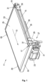
- the conveyor belt shown is part of a conveyor belt scale, for example a checkweigher or a price labeler, which is placed on a scale unit with at least one load cell, in particular up to four load cells, of the conveyor belt scale.
- the conveyor belt shown is then a weighing belt 11.
- the weighing belt 11 is usually connected between a feed belt and a discharge belt, which in a special embodiment can also have the inventive features of the weighing belt 11.
- piece goods or weighing goods can be transported over the scale unit in order to determine the weight of the respective piece goods.
- the weight is usually determined during the further transport of the respective piece goods. In principle, however, the transport process can also be stopped to determine the weight.
- the weighing belt 11, which transports the piece goods in a transport direction 13, comprises a belt body 15, in particular made of aluminum, which is arranged between a first transport roller 17, which is designed as a drive roller, and a second transport roller 19, which is designed as a follower roller.
- the first transport roller 17 and the second transport roller 19 are in Fig. 1 largely covered by other components of the weighing belt 11, which will be discussed in more detail below.
- the two transport rollers 17, 19 are each rotatably mounted in two holders 29, which protrude from the belt body 15 on both sides of the belt body 15 in the transport direction 13 or against the transport direction 13.
- the first transport roller 17 is driven by an electric motor 23 via a belt drive 21. which is firmly attached to the belt body 15 via a holding device 27.
- the weighing belt 11 comprises a conveyor belt 25 designed as an endless belt, which runs around the belt body 15 and the two transport rollers 17, 19 when the weighing belt 11 is in operation.
- the weighing belt 11 also comprises four cover plates 31, which are arranged to the left and right of the two transport rollers 17, 19, whereby for the sake of simplicity only the two in Fig. 1 front cover plates 31 are provided with a reference number.
- a protective strip 33 for the conveyor belt 25 is provided on the inlet and outlet sides, which is attached to the belt body 15, via which the weighing belt 11 and a feed belt designed accordingly at least on the outlet side and a discharge belt designed accordingly at least on the inlet side can be lined up end to end.
- the weighing belt 11 has a cover plate 35, in particular made of metal, which is arranged between the top of the belt body 15 and the upper run of the conveyor belt 25, so that the upper run of the conveyor belt 25 rests on the cover plate 35.
- the cover plate 35 extends in the transport direction 13 over the entire length of the belt body 15 and protrudes on both sides below the upper run of the conveyor belt 25.
- a belt guide device with a cross strut 39 is attached to the underside of the belt body 15, at least essentially in the middle, which extends transversely, in particular perpendicularly to the transport direction 13 over a large part of the width or over the entire width of the belt body 15.
- the belt guide device a smooth running of the lower run of the conveyor belt 25 is ensured.
- Fig. 2 shows a weighing belt 11 according to the invention in a view from below.
- the belt body 15 consists of a profile arrangement made up of several profiles 41, 43.
- the profile arrangement comprises five profiles 41 extending in the transport direction 13 of the piece goods and two profiles 43 extending transversely to the transport direction 13 of the piece goods.
- the profiles 41, 43 are each extruded profiles, in particular made of aluminum.
- the belt body 15 forms the framework of the conveyor belt, in particular the weighing belt 11 of a transport scale, and holds other components of the weighing belt 11, in particular the transport rollers 17, 19, which are attached to the belt body 15 by means of brackets 29.
- a belt guide device 51 consists of a cross strut 39 which extends transversely, in particular perpendicularly to the transport direction 13 and is attached at least substantially centrally with screws 53 to the underside of the belt body 15.
- the belt guide device 51 comprises roller bearings 55 which are attached to the cross strut 39 on the side facing the belt body 15 and which protrude at least partially through the cross strut 39 in the direction of the lower run of the conveyor belt.
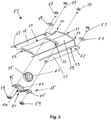
- Fig. 3 shows an exploded view of the belt guide device 51.
- the cross strut 39 is partially shown.
- the cross strut 39 is formed by a bent sheet metal, so that a fold is created in the middle along the longitudinal axis of the cross strut 39 by a central fold 71, which forms a V-shape.
- the inner angle of the V-shape is an obtuse angle, in particular an angle between 135° and 170°, in particular between 150° and 170°.
- the cross strut 39 forms the shape of a channel.
- two fastening rails 75 are attached to the Outer sides of the cross strut 39.
- the fastening rails 75 are horizontal and comprise fastening openings 63 with which the cross strut 39 is fastened to the belt body 15, in particular to the profiles 41 arranged parallel to the transport direction 13, by means of screws 53 and washers 57.
- Recesses 67 are provided along the longitudinal direction of the cross strut 39 and are located in the area of the fold formed by the central bevel 71.
- the recesses 67 have a rectangular, elongated shape, the long side of which is oriented along the transport direction 13.
- the rolling bearings 55 partially protrude through the cross strut 39 through the recesses 67.
- several recesses 67 are provided for several rolling bearings 55, which are arranged in particular at regular intervals along the longitudinal direction of the cross strut 39.
- the rolling bearings 55 are commercially available rolling bearings, in particular ball bearings or roller bearings with an inner ring and an outer ring, wherein the inner ring and the outer ring are arranged so as to be movable relative to one another via a bearing arrangement, i.e. so as to be rotatable relative to one another.
- the inner ring of the rolling bearings is placed on an axle 61.
- the rolling bearing 55 is attached together with the axle on the inside of the cross strut 39, i.e. within the groove of the cross strut 39. This side is the side facing the belt body 15.
- the axle 61 is oriented along the fold formed by the central bevel 71 and is held in its radial direction in this fold.
- the rolling bearing and the axle 61 are fixed with the aid of a counterholder 65.
- the counterholder 65 is fastened with screws 69 and nuts 59 in the area of the recess 67 on the side of the cross strut 39 facing the belt body 15.
- the counterholder 85 consists of a V-shaped sheet metal.
- the V-shape is formed by a central bevel 81.
- the ends of the sheet metal are beveled and form fastening tabs 85 that run parallel to the V-shape of the cross strut 39.
- the counterholder 65 is attached to the cross strut 39 using the fastening tabs 85 with screws 69 and nuts 59.
- the counterholder 65 comprises a recess 87 through which the rolling bearing 55 partially protrudes.
- the counterholder 65 comprises a stop 83 on each side, which limits an axial displacement of the axis 61.
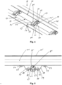
- Fig. 4 a section of the belt guide device 51 is shown.
- the roller bearings 55 are attached to the cross strut 39 by means of the counterholders 65.
- the view shows the belt guide device 51 from the side facing the belt body 15.
- FIG. 5 A side view of the conveyor belt in the area of the belt guide device is shown. The transport belt is not shown for the sake of clarity.
- Fig. 5 shows how the cross strut 39 is screwed to the profile using screws 53 and washers 57 at the fastening openings of the fastening rails.
- the axis 61 on which the inner ring of the roller bearing 55 is attached, lies in the V-shape of the cross strut 39, which is formed by the central bend.
- the counterholder 65 which forms a V-shape in the opposite direction to the cross strut 39 due to a bend 81, is screwed to the cross strut 39 at its fastening tabs 85 using screws 69 and nuts 59.
- Counter-rotating does not mean that the V-shape of the cross strut 39 and the V-shape of the counterholder 65 have the same angle, but that their direction is oriented in opposite directions. In this way, a space is formed between the cross strut 39 and the counterholder 65, in which the axis 61 can be accommodated.
- the counterholder 65 comprises a stop 83.
- a cover plate 35 is attached, over which the conveyor belt (not shown) slides.
- the roller bearing 55 projects through the recess in the cross strut 39 and forms a support for the rotating conveyor belt below the cross strut 39, on the side facing away from the profile 41.
- the rotating conveyor belt is supported by part of the outside of the outer ring of the roller bearing 55.
- Fig. 6 shows a counterholder 65 for mounting a roller bearing on a cross strut of the belt guide device.
- the counterholder 65 is a bent sheet metal part that forms a V-shape by means of a central bevel 81.
- a further bevel 89 towards each end forms a fastening tab 85.
- the fastening tabs 85 run parallel to the V-shape of the cross strut, to which the counterholder 65 is screwed.
- the fastening tabs 85 have a hole for screwing the counterholder 65 to the cross strut.
- the V-shape of the counterholder 65 and the V-shape of the cross strut form a cavity in which an axle that carries a roller bearing can be accommodated. Since the V-shape of the cross strut 39 and the V-shape of the counterholder 65 can have different angles, the cavity does not have to have a rectangular cross-section.
- a stop 83 is provided on both sides of the counterholder. The distance between the two stops 83 is slightly greater than the length of the axle, so that the axles have some play in the axial direction.
- the counterholder comprises a recess 87 through which the rolling bearing, which is mounted on an axle, protrudes.
- Guide knobs 93 protrude into the recess 87 from both sides. These guide knobs are arranged at the level of the inner ring of the rolling bearing and touch the inner rings of the rolling bearings. This prevents the rolling bearing from slipping along the axle within the recess.
Landscapes
- Physics & Mathematics (AREA)
- General Physics & Mathematics (AREA)
- Engineering & Computer Science (AREA)
- Mechanical Engineering (AREA)
- Structure Of Belt Conveyors (AREA)
Claims (15)
- Convoyeur à bande pour le transport de marchandises, en particulier pour une balance à convoyeur à bande, qui comprend un corps de convoyeur (15) avec un côté supérieur, un côté inférieur et une longueur s'étendant dans la direction (13) de transport des marchandises, et une bande de transport (25) tournant autour du corps de convoyeur (15) pendant le fonctionnement du convoyeur à bande, un dispositif (51) de guidage de bande étant monté sur le côté inférieur du corps de convoyeur entre le corps de convoyeur (15) et la bande de transport (25), caractérisé en ce que le dispositif (51) de guidage de bande comprend au moins deux roulements (55), les bagues intérieures des roulements (55) étant montées chacune sur un axe (61) et les axes (61) étant parallèles entre eux et fixes par rapport au corps de convoyeur (15), et les bagues extérieures des roulements (55) étant en contact direct avec la bande de transport (25), et les roulements étant étroits en comparaison de la largeur de la bande de transport et soutenant ponctuellement la bande de transport.
- Convoyeur à bande selon la revendication 1, caractérisé en ce que le dispositif (51) de guidage de bande est constitué d'une traverse (39) qui est montée sur le côté inférieur du corps de convoyeur (15), en particulier au moins sensiblement au milieu, et qui s'étend transversalement, en particulier perpendiculairement, à la direction de transport (13), sur une grande partie de la largeur ou sur toute la largeur du corps de convoyeur (15).
- Convoyeur à bande selon la revendication 2, caractérisé en ce que les roulements (55) sont montés avec des contre-supports (65) sur la traverse (39) du dispositif (51) de guidage de bande.
- Convoyeur à bande selon la revendication 2 ou 3, caractérisé en ce que la traverse (39) comprend, dans des zones prévues pour recevoir des roulements (55), des pliages (71) qui s'étendent sur la longueur de la traverse (39).
- Convoyeur à bande selon la revendication 4, caractérisé en ce que la traverse (39) comprend un pliage continu (71) qui s'étend sur toute la longueur de la traverse (39) pour former des zones destinées à recevoir des roulements (55).
- Convoyeur à bande selon la revendication 4 ou 5, caractérisé en ce que les axes (61) sur lesquels sont montées les bagues intérieures des roulements (55) sont maintenues par des contre-supports (65) en forme de V de la traverse (39) formés par les plis (71).
- Convoyeur à bande selon l'une quelconque des revendications 1 à 6, caractérisé en ce que les contre-supports (65) comprennent chacun deux butées (83) qui limitent la position d'un axe (61) dans sa direction axiale.
- Convoyeur à bande selon l'une quelconque des revendications 2 à 7, caractérisé en ce que la traverse (39) a la forme d'une gouttière présentant une forme en V centrée le long de son axe, l'angle intérieur étant un angle obtus, notamment un angle compris entre 135° et 170°, en particulier entre 150° et 170°.
- Convoyeur à bande selon la revendication 8, caractérisé en ce que les extrémités latérales de la traverse (39) en forme de gouttière présentent d'autres pliages (73, 77) et des ouvertures de fixation (63), la traverse (39) étant vissée au corps de convoyeur (15) au niveau des ouvertures de fixation (63).
- Convoyeur à bande selon l'une quelconque des revendications 1 à 9, caractérisé en ce que les roulements (55) sont des roulements à billes ou à rouleaux.
- Convoyeur à bande selon l'une des revendications 2 à 10, caractérisé en ce que la traverse (39) est formée d'une tôle pliée, les axes (61) sur lesquels sont montés les roulements (55) étant montés sur la traverse (39) du côté tourné vers le corps de convoyeur (15) et la traverse (39) comprenant des évidements (67), à travers lesquels les roulements (55) font partiellement saillie à travers la traverse (39), et en ce que la bande de transport (25) est au moins partiellement en contact avec la partie des roulements (55) qui fait saillie à travers l'évidement (67) de la traverse (39).
- Convoyeur à bande selon l'une quelconque des revendications 3 à 11, caractérisé en ce que chaque contre-support (65) est constitué d'une tôle en forme de V pliée à ses extrémités et présentant un évidement (87) à travers lequel les roulements (55) font partiellement saillie.
- Convoyeur à bande selon la revendication 12, caractérisé en ce que les contre-supports (65) sont reliés à la traverse (39), notamment vissés ou rivetés, et les évidements (67) pour les roulements dans la traverse (39) et les évidements (87) pour les roulements (55) dans les contre-supports (65) sont alignés les uns avec les autres, et des espaces creux sont formés entre la traverse (39) et les contre-supports (65), lesquels forment un logement pour les axes (61) sur lesquels sont montés les roulements (55).
- Convoyeur à bande selon l'une quelconque des revendications 12 à 13, caractérisé en ce que des plots de guidage (93) font saillie de part et d'autre de l'évidement (87) du contre-support (65) et sont disposés au niveau de la bague intérieure du roulement (55).
- Balance à convoyeur à bande comprenant une unité de pesage ayant au moins une cellule de pesage et un convoyeur à bande selon l'une des revendications précédentes, placé sur l'unité de pesage.
Priority Applications (1)
| Application Number | Priority Date | Filing Date | Title |
|---|---|---|---|
| EP23000180.2A EP4332024B1 (fr) | 2020-10-16 | 2020-10-16 | Balance à bande transporteuse avec bande transporteuse et corps de bande transporteuse |
Applications Claiming Priority (2)
| Application Number | Priority Date | Filing Date | Title |
|---|---|---|---|
| EP20202423.8A EP3985363B1 (fr) | 2020-10-16 | 2020-10-16 | Balance pourvue d'une bande transporteuse et corps de bande transporteuse |
| EP23000180.2A EP4332024B1 (fr) | 2020-10-16 | 2020-10-16 | Balance à bande transporteuse avec bande transporteuse et corps de bande transporteuse |
Related Parent Applications (1)
| Application Number | Title | Priority Date | Filing Date |
|---|---|---|---|
| EP20202423.8A Division EP3985363B1 (fr) | 2020-10-16 | 2020-10-16 | Balance pourvue d'une bande transporteuse et corps de bande transporteuse |
Publications (3)
| Publication Number | Publication Date |
|---|---|
| EP4332024A2 EP4332024A2 (fr) | 2024-03-06 |
| EP4332024A3 EP4332024A3 (fr) | 2024-05-29 |
| EP4332024B1 true EP4332024B1 (fr) | 2024-12-04 |
Family
ID=73013167
Family Applications (2)
| Application Number | Title | Priority Date | Filing Date |
|---|---|---|---|
| EP23000180.2A Active EP4332024B1 (fr) | 2020-10-16 | 2020-10-16 | Balance à bande transporteuse avec bande transporteuse et corps de bande transporteuse |
| EP20202423.8A Active EP3985363B1 (fr) | 2020-10-16 | 2020-10-16 | Balance pourvue d'une bande transporteuse et corps de bande transporteuse |
Family Applications After (1)
| Application Number | Title | Priority Date | Filing Date |
|---|---|---|---|
| EP20202423.8A Active EP3985363B1 (fr) | 2020-10-16 | 2020-10-16 | Balance pourvue d'une bande transporteuse et corps de bande transporteuse |
Country Status (2)
| Country | Link |
|---|---|
| US (1) | US11604090B2 (fr) |
| EP (2) | EP4332024B1 (fr) |
Families Citing this family (1)
| Publication number | Priority date | Publication date | Assignee | Title |
|---|---|---|---|---|
| CN117232629B (zh) * | 2023-03-10 | 2024-05-14 | 中山精量衡器制造有限公司 | 一种物流称重的通用称重装置 |
Family Cites Families (7)
| Publication number | Priority date | Publication date | Assignee | Title |
|---|---|---|---|---|
| JPS5172463A (en) * | 1974-12-20 | 1976-06-23 | Kubota Ltd | Konbeya sukeeruniokeru juryosekisansochi |
| DK170003B1 (da) | 1992-10-05 | 1995-04-24 | Jesma Matador As | Båndvægt |
| CA2456051C (fr) | 2001-08-03 | 2011-03-01 | Marel Hf | Appareil et procede permettant de commander la tension de courroie d'une bascule a courroie |
| JP3908048B2 (ja) | 2002-02-05 | 2007-04-25 | 株式会社イシダ | X線検査装置 |
| DE102007032270A1 (de) | 2007-07-11 | 2009-01-15 | Mettler-Toledo Garvens Gmbh | Vorrichtung zum Prüfen von Produkten und Prüfverfahren |
| CN203624355U (zh) | 2013-10-31 | 2014-06-04 | 徐义祥 | 一种称重传送机 |
| CN111372875B (zh) * | 2017-12-13 | 2026-01-13 | 莱特拉姆有限责任公司 | 卫生中空框架组合件 |
-
2020
- 2020-10-16 EP EP23000180.2A patent/EP4332024B1/fr active Active
- 2020-10-16 EP EP20202423.8A patent/EP3985363B1/fr active Active
-
2021
- 2021-10-11 US US17/497,985 patent/US11604090B2/en active Active
Also Published As
| Publication number | Publication date |
|---|---|
| EP3985363A1 (fr) | 2022-04-20 |
| US20220120603A1 (en) | 2022-04-21 |
| US11604090B2 (en) | 2023-03-14 |
| EP4332024A3 (fr) | 2024-05-29 |
| EP3985363B1 (fr) | 2023-12-27 |
| EP4332024A2 (fr) | 2024-03-06 |
Similar Documents
| Publication | Publication Date | Title |
|---|---|---|
| EP2368817B1 (fr) | Dispositif de guidage | |
| EP3746380A1 (fr) | Convoyeur à bande, en particulier convoyeur peseur à bande | |
| WO2021151433A1 (fr) | Convoyeur à bande modulaire | |
| DE102013203457B4 (de) | Gestell einer Wäge-Fördervorrichtung | |
| DE3922397C2 (fr) | ||
| DE3724240A1 (de) | Vorrichtung zum sortieren von teilen | |
| EP4332024B1 (fr) | Balance à bande transporteuse avec bande transporteuse et corps de bande transporteuse | |
| EP3565772A1 (fr) | Dispositif d'amenée et procédé permettant de mettre au point un dispositif d'amenée | |
| DE3913019A1 (de) | Spaenefoerderer | |
| EP1714917B1 (fr) | Convoyeur à rouleaux | |
| DE19532391C2 (de) | Antriebseinheit für ein endloses Fördermittel eines Fördersystem | |
| DE3313196C1 (de) | Vorrichtung zum Spannen eines bandförmigen Förderorganes | |
| EP0121920B1 (fr) | Dispositif de transport à bande | |
| DE102017011293B4 (de) | Laufbahn, Fördereinrichtung und Verfahren zur Montage einer Laufbahn | |
| DE102021126860A1 (de) | Umlenkelement | |
| EP0678463A2 (fr) | Transporteur à chaîne | |
| EP0121921B1 (fr) | Dispositif de serrage d'une installation de transport en forme de ruban | |
| DE102006053913B4 (de) | Fördereinrichtung für Lastträger | |
| DE102017011303B4 (de) | Kugellagermodul und Verfahren zur Montage eines Kugellagermoduls | |
| DE102013211442B4 (de) | Umlenkeinrichtung für einen Kettenförderer | |
| CH677915A5 (fr) | ||
| DE102004009842B4 (de) | Staurollenförderer | |
| DE19914515A1 (de) | Antriebssystem | |
| WO2019110349A1 (fr) | Dispositif de transport | |
| EP1190966B1 (fr) | Dispositif de transport |
Legal Events
| Date | Code | Title | Description |
|---|---|---|---|
| PUAI | Public reference made under article 153(3) epc to a published international application that has entered the european phase |
Free format text: ORIGINAL CODE: 0009012 |
|
| STAA | Information on the status of an ep patent application or granted ep patent |
Free format text: STATUS: THE APPLICATION HAS BEEN PUBLISHED |
|
| AC | Divisional application: reference to earlier application |
Ref document number: 3985363 Country of ref document: EP Kind code of ref document: P |
|
| AK | Designated contracting states |
Kind code of ref document: A2 Designated state(s): AL AT BE BG CH CY CZ DE DK EE ES FI FR GB GR HR HU IE IS IT LI LT LU LV MC MK MT NL NO PL PT RO RS SE SI SK SM TR |
|
| REG | Reference to a national code |
Ref country code: DE Free format text: PREVIOUS MAIN CLASS: B65G0015600000 Ipc: G01G0023120000 Ref country code: DE Ref legal event code: R079 Ref document number: 502020009921 Country of ref document: DE Free format text: PREVIOUS MAIN CLASS: B65G0015600000 Ipc: G01G0023120000 |
|
| PUAL | Search report despatched |
Free format text: ORIGINAL CODE: 0009013 |
|
| AK | Designated contracting states |
Kind code of ref document: A3 Designated state(s): AL AT BE BG CH CY CZ DE DK EE ES FI FR GB GR HR HU IE IS IT LI LT LU LV MC MK MT NL NO PL PT RO RS SE SI SK SM TR |
|
| RIC1 | Information provided on ipc code assigned before grant |
Ipc: B65G 15/60 20060101ALI20240419BHEP Ipc: B65G 39/09 20060101ALI20240419BHEP Ipc: G01G 19/03 20060101ALI20240419BHEP Ipc: G01G 11/00 20060101ALI20240419BHEP Ipc: G01G 23/12 20060101AFI20240419BHEP |
|
| STAA | Information on the status of an ep patent application or granted ep patent |
Free format text: STATUS: REQUEST FOR EXAMINATION WAS MADE |
|
| 17P | Request for examination filed |
Effective date: 20240613 |
|
| RBV | Designated contracting states (corrected) |
Designated state(s): AL AT BE BG CH CY CZ DE DK EE ES FI FR GB GR HR HU IE IS IT LI LT LU LV MC MK MT NL NO PL PT RO RS SE SI SK SM TR |
|
| GRAP | Despatch of communication of intention to grant a patent |
Free format text: ORIGINAL CODE: EPIDOSNIGR1 |
|
| STAA | Information on the status of an ep patent application or granted ep patent |
Free format text: STATUS: GRANT OF PATENT IS INTENDED |
|
| INTG | Intention to grant announced |
Effective date: 20240917 |
|
| GRAS | Grant fee paid |
Free format text: ORIGINAL CODE: EPIDOSNIGR3 |
|
| GRAA | (expected) grant |
Free format text: ORIGINAL CODE: 0009210 |
|
| STAA | Information on the status of an ep patent application or granted ep patent |
Free format text: STATUS: THE PATENT HAS BEEN GRANTED |
|
| AC | Divisional application: reference to earlier application |
Ref document number: 3985363 Country of ref document: EP Kind code of ref document: P |
|
| AK | Designated contracting states |
Kind code of ref document: B1 Designated state(s): AL AT BE BG CH CY CZ DE DK EE ES FI FR GB GR HR HU IE IS IT LI LT LU LV MC MK MT NL NO PL PT RO RS SE SI SK SM TR |
|
| REG | Reference to a national code |
Ref country code: CH Ref legal event code: EP |
|
| REG | Reference to a national code |
Ref country code: DE Ref legal event code: R096 Ref document number: 502020009921 Country of ref document: DE |
|
| REG | Reference to a national code |
Ref country code: IE Ref legal event code: FG4D Free format text: LANGUAGE OF EP DOCUMENT: GERMAN |
|
| REG | Reference to a national code |
Ref country code: LT Ref legal event code: MG9D |
|
| REG | Reference to a national code |
Ref country code: NL Ref legal event code: MP Effective date: 20241204 |
|
| PG25 | Lapsed in a contracting state [announced via postgrant information from national office to epo] |
Ref country code: HR Free format text: LAPSE BECAUSE OF FAILURE TO SUBMIT A TRANSLATION OF THE DESCRIPTION OR TO PAY THE FEE WITHIN THE PRESCRIBED TIME-LIMIT Effective date: 20241204 |
|
| PG25 | Lapsed in a contracting state [announced via postgrant information from national office to epo] |
Ref country code: FI Free format text: LAPSE BECAUSE OF FAILURE TO SUBMIT A TRANSLATION OF THE DESCRIPTION OR TO PAY THE FEE WITHIN THE PRESCRIBED TIME-LIMIT Effective date: 20241204 |
|
| PG25 | Lapsed in a contracting state [announced via postgrant information from national office to epo] |
Ref country code: BG Free format text: LAPSE BECAUSE OF FAILURE TO SUBMIT A TRANSLATION OF THE DESCRIPTION OR TO PAY THE FEE WITHIN THE PRESCRIBED TIME-LIMIT Effective date: 20241204 |
|
| PG25 | Lapsed in a contracting state [announced via postgrant information from national office to epo] |
Ref country code: ES Free format text: LAPSE BECAUSE OF FAILURE TO SUBMIT A TRANSLATION OF THE DESCRIPTION OR TO PAY THE FEE WITHIN THE PRESCRIBED TIME-LIMIT Effective date: 20241204 |
|
| PG25 | Lapsed in a contracting state [announced via postgrant information from national office to epo] |
Ref country code: NO Free format text: LAPSE BECAUSE OF FAILURE TO SUBMIT A TRANSLATION OF THE DESCRIPTION OR TO PAY THE FEE WITHIN THE PRESCRIBED TIME-LIMIT Effective date: 20250304 |
|
| PG25 | Lapsed in a contracting state [announced via postgrant information from national office to epo] |
Ref country code: GR Free format text: LAPSE BECAUSE OF FAILURE TO SUBMIT A TRANSLATION OF THE DESCRIPTION OR TO PAY THE FEE WITHIN THE PRESCRIBED TIME-LIMIT Effective date: 20250305 Ref country code: LV Free format text: LAPSE BECAUSE OF FAILURE TO SUBMIT A TRANSLATION OF THE DESCRIPTION OR TO PAY THE FEE WITHIN THE PRESCRIBED TIME-LIMIT Effective date: 20241204 |
|
| PG25 | Lapsed in a contracting state [announced via postgrant information from national office to epo] |
Ref country code: RS Free format text: LAPSE BECAUSE OF FAILURE TO SUBMIT A TRANSLATION OF THE DESCRIPTION OR TO PAY THE FEE WITHIN THE PRESCRIBED TIME-LIMIT Effective date: 20250304 |
|
| PG25 | Lapsed in a contracting state [announced via postgrant information from national office to epo] |
Ref country code: NL Free format text: LAPSE BECAUSE OF FAILURE TO SUBMIT A TRANSLATION OF THE DESCRIPTION OR TO PAY THE FEE WITHIN THE PRESCRIBED TIME-LIMIT Effective date: 20241204 |
|
| PG25 | Lapsed in a contracting state [announced via postgrant information from national office to epo] |
Ref country code: SM Free format text: LAPSE BECAUSE OF FAILURE TO SUBMIT A TRANSLATION OF THE DESCRIPTION OR TO PAY THE FEE WITHIN THE PRESCRIBED TIME-LIMIT Effective date: 20241204 |
|
| PG25 | Lapsed in a contracting state [announced via postgrant information from national office to epo] |
Ref country code: PL Free format text: LAPSE BECAUSE OF FAILURE TO SUBMIT A TRANSLATION OF THE DESCRIPTION OR TO PAY THE FEE WITHIN THE PRESCRIBED TIME-LIMIT Effective date: 20241204 |
|
| PG25 | Lapsed in a contracting state [announced via postgrant information from national office to epo] |
Ref country code: IS Free format text: LAPSE BECAUSE OF FAILURE TO SUBMIT A TRANSLATION OF THE DESCRIPTION OR TO PAY THE FEE WITHIN THE PRESCRIBED TIME-LIMIT Effective date: 20250404 |
|
| PG25 | Lapsed in a contracting state [announced via postgrant information from national office to epo] |
Ref country code: PT Free format text: LAPSE BECAUSE OF FAILURE TO SUBMIT A TRANSLATION OF THE DESCRIPTION OR TO PAY THE FEE WITHIN THE PRESCRIBED TIME-LIMIT Effective date: 20250404 |
|
| PG25 | Lapsed in a contracting state [announced via postgrant information from national office to epo] |
Ref country code: EE Free format text: LAPSE BECAUSE OF FAILURE TO SUBMIT A TRANSLATION OF THE DESCRIPTION OR TO PAY THE FEE WITHIN THE PRESCRIBED TIME-LIMIT Effective date: 20241204 |
|
| PG25 | Lapsed in a contracting state [announced via postgrant information from national office to epo] |
Ref country code: RO Free format text: LAPSE BECAUSE OF FAILURE TO SUBMIT A TRANSLATION OF THE DESCRIPTION OR TO PAY THE FEE WITHIN THE PRESCRIBED TIME-LIMIT Effective date: 20241204 |
|
| PG25 | Lapsed in a contracting state [announced via postgrant information from national office to epo] |
Ref country code: SK Free format text: LAPSE BECAUSE OF FAILURE TO SUBMIT A TRANSLATION OF THE DESCRIPTION OR TO PAY THE FEE WITHIN THE PRESCRIBED TIME-LIMIT Effective date: 20241204 |
|
| PG25 | Lapsed in a contracting state [announced via postgrant information from national office to epo] |
Ref country code: CZ Free format text: LAPSE BECAUSE OF FAILURE TO SUBMIT A TRANSLATION OF THE DESCRIPTION OR TO PAY THE FEE WITHIN THE PRESCRIBED TIME-LIMIT Effective date: 20241204 |
|
| PG25 | Lapsed in a contracting state [announced via postgrant information from national office to epo] |
Ref country code: IT Free format text: LAPSE BECAUSE OF FAILURE TO SUBMIT A TRANSLATION OF THE DESCRIPTION OR TO PAY THE FEE WITHIN THE PRESCRIBED TIME-LIMIT Effective date: 20241204 |
|
| REG | Reference to a national code |
Ref country code: DE Ref legal event code: R097 Ref document number: 502020009921 Country of ref document: DE |
|
| PG25 | Lapsed in a contracting state [announced via postgrant information from national office to epo] |
Ref country code: SE Free format text: LAPSE BECAUSE OF FAILURE TO SUBMIT A TRANSLATION OF THE DESCRIPTION OR TO PAY THE FEE WITHIN THE PRESCRIBED TIME-LIMIT Effective date: 20241204 |
|
| PG25 | Lapsed in a contracting state [announced via postgrant information from national office to epo] |
Ref country code: DK Free format text: LAPSE BECAUSE OF FAILURE TO SUBMIT A TRANSLATION OF THE DESCRIPTION OR TO PAY THE FEE WITHIN THE PRESCRIBED TIME-LIMIT Effective date: 20241204 |
|
| PLBE | No opposition filed within time limit |
Free format text: ORIGINAL CODE: 0009261 |
|
| STAA | Information on the status of an ep patent application or granted ep patent |
Free format text: STATUS: NO OPPOSITION FILED WITHIN TIME LIMIT |
|
| 26N | No opposition filed |
Effective date: 20250905 |
|
| PGFP | Annual fee paid to national office [announced via postgrant information from national office to epo] |
Ref country code: DE Payment date: 20251020 Year of fee payment: 6 |
|
| PGFP | Annual fee paid to national office [announced via postgrant information from national office to epo] |
Ref country code: GB Payment date: 20251024 Year of fee payment: 6 |
|
| PGFP | Annual fee paid to national office [announced via postgrant information from national office to epo] |
Ref country code: FR Payment date: 20251029 Year of fee payment: 6 |