EP3987100B1 - Drückerfussmodul für eine tuftingmaschine - Google Patents
Drückerfussmodul für eine tuftingmaschine Download PDFInfo
- Publication number
- EP3987100B1 EP3987100B1 EP20734484.7A EP20734484A EP3987100B1 EP 3987100 B1 EP3987100 B1 EP 3987100B1 EP 20734484 A EP20734484 A EP 20734484A EP 3987100 B1 EP3987100 B1 EP 3987100B1
- Authority
- EP
- European Patent Office
- Prior art keywords
- fingers
- module
- finger
- tufting machine
- presser foot
- Prior art date
- Legal status (The legal status is an assumption and is not a legal conclusion. Google has not performed a legal analysis and makes no representation as to the accuracy of the status listed.)
- Active
Links
Images


Classifications
-
- D—TEXTILES; PAPER
- D05—SEWING; EMBROIDERING; TUFTING
- D05C—EMBROIDERING; TUFTING
- D05C15/00—Making pile fabrics or articles having similar surface features by inserting loops into a base material
- D05C15/04—Tufting
- D05C15/08—Tufting machines
-
- D—TEXTILES; PAPER
- D05—SEWING; EMBROIDERING; TUFTING
- D05C—EMBROIDERING; TUFTING
- D05C15/00—Making pile fabrics or articles having similar surface features by inserting loops into a base material
- D05C15/04—Tufting
- D05C15/08—Tufting machines
- D05C15/14—Arrangements or devices for holding or feeding the base material
-
- D—TEXTILES; PAPER
- D05—SEWING; EMBROIDERING; TUFTING
- D05C—EMBROIDERING; TUFTING
- D05C15/00—Making pile fabrics or articles having similar surface features by inserting loops into a base material
- D05C15/04—Tufting
- D05C15/08—Tufting machines
- D05C15/16—Arrangements or devices for manipulating threads
-
- D—TEXTILES; PAPER
- D05—SEWING; EMBROIDERING; TUFTING
- D05B—SEWING
- D05B29/00—Pressers; Presser feet
-
- D—TEXTILES; PAPER
- D05—SEWING; EMBROIDERING; TUFTING
- D05C—EMBROIDERING; TUFTING
- D05C15/00—Making pile fabrics or articles having similar surface features by inserting loops into a base material
- D05C15/04—Tufting
- D05C15/08—Tufting machines
- D05C15/10—Tufting machines operating with a plurality of needles, e.g. in one row
-
- D—TEXTILES; PAPER
- D05—SEWING; EMBROIDERING; TUFTING
- D05C—EMBROIDERING; TUFTING
- D05C15/00—Making pile fabrics or articles having similar surface features by inserting loops into a base material
- D05C15/04—Tufting
- D05C15/08—Tufting machines
- D05C15/16—Arrangements or devices for manipulating threads
- D05C15/22—Loop-catching arrangements, e.g. loopers; Driving mechanisms therefor
Definitions
- the present invention relates to a presser foot module for a tufting machine.
- a presser foot module is a gauge part of a tufting machine.
- the modules are attached to a presser foot bar. This is a bar which is mounted immediately above the backing medium which is fed through a tufting machine.
- the presser foot module is distinct from other tufting machine gauge parts such as the hooks, needles and reeds.
- a conventional presser foot module comprises two main parts, namely a module body and a plurality of fingers extending from the body.
- the module body is provided with an opening via which the module is mounted to the presser foot bar.
- the underside of the body acts as a presser surface pressing yarns against the rear face of the backing medium following after the yarns have been tufted into the backing medium.
- the presser foot exerts a pressure on these to ensure that they are kept roughly in the right position such that any interference with adjacent yarns is minimised without the yarns being lost out of the needle eye.
- a plurality of fingers protrude. These have a flat plate like structure and protrude from the module body in a direction which, in use, is opposite to the direction in which the backing medium is fed through the tufting machine.
- the fingers have a relatively longitudinal dimension and therefore, in order to prevent them from being deflected and distorted in use as they move sideways with the needle bar, a bar extends across the distal end of the fingers to enhance rigidity. This creates a number of gaps between the module body, two adjacent fingers and the bar at the distal end through which, in use, a needle of a tufting machine reciprocates in order to form a tuft in the carpet.
- the fingers provide barriers in order to separate the yarn from the yarn of an adjacent needle so as to minimise cross stitching.
- the needles are reciprocated in and out of the gap between an adjacent pair of fingers. This causes a problem in that yarn can become trapped between the fingers and the needles. This is less of a problem in a cut pile yarn where the tensions are higher.
- the loops are more sensitive to trapping between the fingers and the needles because the loops are released from the hooks each time a loop is formed rather than remaining wrapped around the looper for a cut pile.
- the present invention aims at improving the design of the presser foot to address these problems.
- GB1120038 and JP S58-203152 disclose a presser foot module according to the preamble of claim 1. According to a first aspect of the invention, such a module is characterised by the characterising feature of claim 1.
- the lip provides a presser surface which is significantly narrower than the presser surface of the prior art which has no such lip.
- the presser foot allows a higher pressure to be applied to the yarn across a narrower and more controlled area. This higher pressure provides better holding of the yarn in that area.
- the total frictional load applied to the yarn can be significantly lower as the yarn is in contact with the presser foot for a much shorter proportion of its travel. This reduces the possibility of damaging the yarn.
- the invention provides improved yarn control and reduced damage.
- the lip is relatively narrow.
- the dimension of the downwardly depending lip in the first direction is less than 1.5 times the pitch of the fingers and more preferably, is less than the pitch of the fingers.
- the pitch of the fingers represents the separation between adjacent fingers.
- the dimension of the downwardly depending lip in the first direction is greater than 0.5 times the pitch of the fingers.
- the lower edge of each finger has a groove. This helps to keep the yarn in place in a controlled position which is away from any stitch location of a subsequent stitch
- each finger In a presser foot module, the fingers typically do not extend below the presser surface, unlike in a hook module where the hooks extend beyond the surface of the body which is opposite to the side which is attached to the tufting machine.
- at least part of the lower edge of each finger is typically greater than 0.5 mm and preferably at least 1 mm above the presser surface. This is different from the bed plate where the tops of the reeds are as close as possible to the top of the body as these are required to support the backing medium.
- each finger In a presser foot module, each finger is typically formed as a single planar component in a plane transverse to the presser surface. This is fundamentally different from the scissor like mechanism of JPH11124764 in which two comb like structures with sharp edges slide relatively to one another to shear fluff.
- the fingers may have a bar running across the distal end of the fingers to support them at this end.
- each finger has a first end mounted in the module body and a second end opposite to the first end which is unsupported so as to provide access to an open gap between adjacent fingers in a direction opposite to the first direction.
- Such a module provides an advantage over a conventional module that access into the gap between the adjacent teeth is in a direction opposite to the first direction thereby allowing much easier rethreading of a the tufting machine as it is no longer necessary to feed each loose end of yarn downwardly through a gap between adjacent fingers.
- the present invention allows for enhanced inspection of the threading up of a tufting machine as the bar in the prior art obstructs the view into the tufting region of the machine.
- JP H-11 124764 discloses a presser foot module for a tufting machine, the module having a module body with a first side for attachment to a tufting machine and a plurality of fingers extending from the body in a first direction which, in use, is opposite to the direction in which the backing medium is fed through the tufting machine, each finger having a second end opposite to a first end which is unsupported so as to provide access to an open gap between adjacent fingers in a direction opposite to the first direction the module having a second side opposite to the first side provided with a presser surface extending across the body to engage in use, with a backing medium fed through the tufting machine; wherein the fingers do not extend below the presser surface and at least part of the lower edge of each finger is above the presser surface (figure 4).
- the module of the prior art needs to the fingers to be relatively long in order that the bar does not obstruct the reciprocation of the needles.
- the fingers can be significantly shorter.
- the maximum length of the finger to the pitch of the fingers is less than 4, preferably less than 3.5 and most preferably less than 3.
- the shorter fingers are less prone to deflection than the fingers of the prior art.
- the support provided by the bar is no longer required for these smaller fingers thereby leading to a synergy between the absence of the bar and the shorter fingers.
- the present invention also extends to a tufting machine or a presser foot bar to which a plurality of modules according to aspects of the invention set out above are attached.
- the invention also extends to a tufting machine comprising at least one presser foot module as set out above.
- the tufting machine shown in Fig. 1 is, in almost every respect, a known individual needle control (ICN) machine. As this is largely conventional, the main components will be described briefly here.
- ICN individual needle control
- the backing medium 1 (depicted schematically as a dashed line in Fig. 1 ) is fed through the tufting machine in a feed direction depicted by arrow 2 and is supported in the tufting position by a bed plate 3.
- a needle bar 4 supports a line of needles 5 (the line extending in the direction perpendicular to the plane of Fig. 1 ).
- Each needle 5 is supported on a needle support 6.
- Each needle support 6 has an associated latch 7 such that, if the needle 5 is required to be reciprocated in a particular stroke, the needle 5 can be selectively latched to the needle bar 4 so that it will penetrate the backing medium 1 to form a loop of yarn.
- This is well-known in the art as an individual needle control (ICN) machine.
- the loopers 8 will rock forwards to pick up a loop of yarn formed by the needle 5.
- the loopers are preferably level cut loopers (LCL), these have a latching mechanism which is configured either to ensure that the loop of yarn slips off of the looper 8 or alternatively to ensure that it is retained on the looper 8 such that it slides back to a throat 9 of the looper and is cut by a respective knife 10 in order to form a cut pile tuft.
- This mechanism is therefore capable of selectively forming loop or cut pile tufts. Further details of a level cut looper are disclosed, for example, in GB 2367305 or GB 2354263 .
- a presser foot 11 is provided in order to support the backing medium 1 as the needles 5 are pulled through it in the upwards direction in Fig. 1 .
- the presser foot comprises a plurality of fingers 12 and a mounting body 13.
- the presser module can also be used on a conventional tufting machine.
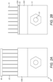
- the presser foot module is shown in greater detail in Figs. 2B and 3 . These show one module 50 of the presser foot. As described above, this has a mounting body 13 from which a plurality of fingers 12 project in a direction opposite to the direction 2 in which the backing medium 1 is fed through the tufting machine. The body 13 is provided with a mounting hole 51 by which the presser foot module 50 is mounted to a presser foot bar 52 ( Fig. 1 ) which is mounted to slide laterally together with the needle bar, but does not reciprocate with the needle bar in the direction of reciprocation of the needles. Instead, it remains in the position shown in Fig. 1 immediately above the backing medium 1.
- the module 50 has three unconventional features.
- a bar 60 extends across the distal end of the figures 12' in order to provide enhanced rigidity.
- Fig. 2B no such bar is present such that there is an open gap at the distal of the fingers 12. This improves the rethreading of the tufting machine as, when passing a yarn through the presser foot, this can be done by moving the yarn laterally between two fingers 12, rather than having two thread a cut end from top to bottom as previously. The replacement of a module is also easier.
- the second modification is the presence of a downwardly depending lip 53 which extends across the module 50 in a downward direction (i.e. in a direction away from the service which is mounted to the presser foot bar 52) such that, in use, only this lip 53 engages with the yarns.
- a downwardly depending lip 53 which extends across the module 50 in a downward direction (i.e. in a direction away from the service which is mounted to the presser foot bar 52) such that, in use, only this lip 53 engages with the yarns.
- the presser surface 53A provided on the lower face of the lip 53 is significantly narrower than the presser surface 53B of the prior art and there is a wide region 53C behind the lip 53 where the yarns do not engage with the presser foot module.
- the fingers 12 have been shortened.
- the ratio of the maximum length of a finger to the pitch of the fingers has been reduced from 4.3 to less than 4, more preferably less than 3.5 and most preferably less than 3. This saves material and reduces weight. Now that the bar is no longer required, the size of the opening between adjacent fingers is no longer an issue in the threading operation.
- each finger 12 has a groove 14 which represents a region where the lower edge is spaced further from the backing medium 1.
- the finger therefore has a position of minimum height part way along its length and increases in height in both directions away from that position.
- the yarns extend down between adjacent fingers and the portions of the yarn which end up on the rear surface of the backing medium 1 then slide under the module body 13.
- the groove 14 allows the yarn to pass readily beneath the lower edge of the finger 12 and helps to keep it in place in a controlled position which is away from any stitch location of a subsequent stitch.
- the yarns By providing the lip 53, rather than the yarn engaging surface across a wide portion of the module 13, the yarns only engage under the lip leading to a reduced frictional force between the presser foot and the yarn. Also, as the lip 53 represents a single line of contact between the presser foot and the yarn, it is easier to control the amount of pressure on the yarn. Control of this pressure is important and it requires a balance between creating a pressure which is high enough to ensure that the loose ends of yarn stay under the presser foot, but which is not high enough to generate undue friction on the yarns.
Landscapes
- Engineering & Computer Science (AREA)
- Textile Engineering (AREA)
- Chemical & Material Sciences (AREA)
- Materials Engineering (AREA)
- Sewing Machines And Sewing (AREA)
- Spinning Or Twisting Of Yarns (AREA)
- Portable Nailing Machines And Staplers (AREA)
Claims (15)
- Drückerfußmodul für eine Tuftingmaschine, wobei das Modul einen Modulkörper (13) zur Befestigung an einer Tuftingmaschine und eine Mehrzahl von Fingern (12) aufweist, die sich von dem Körper in einer ersten Richtung erstrecken, die im Gebrauch entgegengesetzt zu der Richtung ist, in der das Trägermedium (1) durch die Tuftingmaschine geführt wird; dadurch gekennzeichnet, dass der Modulkörper (13) eine nach unten herabhängende Lippe (53) aufweist, die eine Drückeroberfläche (53A) definiert, die sich über ein zur Verbindungsstelle mit den Fingern (12) benachbartes Ende des Körpers erstreckt.
- Modul nach Anspruch 1, bei dem die Abmessung der herunterhängenden Lippe (53) in der ersten Richtung kleiner ist als das 1,5-fache des Abstands der Finger (12).
- Modul nach Anspruch 2, bei dem die Abmessung der herunterhängenden Lippe (53) in der ersten Richtung kleiner ist als der Abstand der Finger (12).
- Modul nach einem der vorhergehenden Ansprüche, bei dem die Abmessung der herunterhängenden Lippe (12) in der ersten Richtung größer ist als das 0,5-fache des Abstands der Finger (12).
- Modul nach einem der vorhergehenden Ansprüche, bei dem jeder Finger (12) ein erstes, im Modulkörper (13) befestigtes Ende und ein zweites, dem ersten Ende gegenüberliegendes Ende aufweist, das freitragend ist, um Zugang zu einem offenen Spalt zwischen benachbarten Fingern in einer zur ersten Richtung entgegengesetzten Richtung zu gewähren.
- Modul nach einem der vorhergehenden Ansprüche, bei dem das Verhältnis zwischen der maximalen Länge eines Fingers (12) und dem Abstand der Finger (12) kleiner ist als 4.
- Modul nach Anspruch 6, bei dem das Verhältnis zwischen der maximalen Länge eines Fingers (12) und dem Abstand der Finger (12) kleiner ist als 3.
- Modul nach einem der vorhergehenden Ansprüche, bei dem die untere Kante jedes Fingers (12) eine Rille aufweist.
- Tuftingmaschine, umfassend:eine Mehrzahl von Nadeln (5), die auf einer ersten Seite einer Ebene angeordnet sind, entlang derer im Betrieb ein Trägermedium durch die Maschine geführt wird, wobei die Nadeln hin- und herbewegbar sind, um das Trägermedium zu durchdringen und eine Garnschlinge auf der zweiten Seite der Ebene zu bilden;eine Mehrzahl von Haken oder Ösen (8), die auf der zweiten Seite der Ebene angeordnet sind, um jeweils von den Nadeln gebildete Garnschlingen aufzunehmen;mindestens ein auf der ersten Seite der Ebene angeordnetes Drückerfußmodul nach Anspruch 1.
- Drückerfußmodul für eine Tuftingmaschine, wobei das Modul einen Modulkörper mit einer ersten Seite zur Befestigung an einer Tuftingmaschine und eine Mehrzahl von Fingern aufweist, die sich von dem Körper in einer ersten Richtung erstrecken, die im Gebrauch entgegengesetzt zu der Richtung ist, in der das Trägermedium durch die Tuftingmaschine geführt wird, wobei jeder Finger ein erstes, im Modulkörper befestigtes Ende und ein zweites, dem ersten Ende gegenüberliegendes Ende aufweist, das freitragend ist, um Zugang zu einem offenen Spalt zwischen benachbarten Fingern in einer zu der ersten Richtung entgegengesetzten Richtung zu gewähren;wobei das Modul eine der ersten Seite gegenüberliegende zweite Seite aufweist, die mit einer Andrückfläche versehen ist, die sich über den Körper erstreckt, um im Gebrauch mit einem durch die Tuftingmaschine geführten Trägermedium in Eingriff zu kommen;wobei sich die Finger nicht unter die Andrückfläche erstrecken;wobei mindestens ein Teil der Unterkante jedes Fingers mehr als 0,5 mm über der Andrückfläche liegt;wobei jeder Finger als ein einzelnes ebenes Bauteil in einer quer zur Drückeroberfläche liegenden Ebene ausgebildet ist.
- Modul nach Anspruch 11, bei dem die untere Kante jedes Fingers eine Rille aufweist.
- Modul nach Anspruch 11, bei dem das Verhältnis zwischen der maximalen Länge eines Fingers und dem Abstand der Finger kleiner ist als 4.
- Modul nach Anspruch 12, bei dem das Verhältnis zwischen der maximalen Länge eines Fingers und dem Abstand der Finger kleiner ist als 3.
- Tuftingmaschine miteiner Mehrzahl von Nadeln (5), die auf einer ersten Seite einer Ebene angeordnet sind, entlang derer im Betrieb ein Trägermedium durch die Maschine geführt wird, wobei die Nadeln hin- und herbeweglich sind, um das Trägermedium zu durchdringen und eine Garnschlinge auf der zweiten Seite der Ebene zu bilden;einer Mehrzahl von Haken oder Ösen (8), die auf der zweiten Seite der Ebene angeordnet sind, um jeweils von den Nadeln gebildete Garnschlingen aufzunehmen;mindestens einem auf der ersten Seite der Ebene angeordnetes Drückerfußmodul nach Anspruch 10.
- Drückerfußleiste mit mindestens einem Drückerfußmodul nach einem der Ansprüche 1 bis 8 und 10 bis 13.
Applications Claiming Priority (2)
| Application Number | Priority Date | Filing Date | Title |
|---|---|---|---|
| GB1908846.7A GB2587777A (en) | 2019-06-20 | 2019-06-20 | A presser foot module for a tufting machine |
| PCT/EP2020/067037 WO2020254536A1 (en) | 2019-06-20 | 2020-06-18 | A presser foot module for a tufting machine |
Publications (3)
| Publication Number | Publication Date |
|---|---|
| EP3987100A1 EP3987100A1 (de) | 2022-04-27 |
| EP3987100C0 EP3987100C0 (de) | 2023-12-27 |
| EP3987100B1 true EP3987100B1 (de) | 2023-12-27 |
Family
ID=67511596
Family Applications (1)
| Application Number | Title | Priority Date | Filing Date |
|---|---|---|---|
| EP20734484.7A Active EP3987100B1 (de) | 2019-06-20 | 2020-06-18 | Drückerfussmodul für eine tuftingmaschine |
Country Status (9)
| Country | Link |
|---|---|
| US (1) | US12221731B2 (de) |
| EP (1) | EP3987100B1 (de) |
| CN (1) | CN114127352B (de) |
| AU (1) | AU2020296931A1 (de) |
| ES (1) | ES2971692T3 (de) |
| GB (1) | GB2587777A (de) |
| PL (1) | PL3987100T3 (de) |
| WO (1) | WO2020254536A1 (de) |
| ZA (1) | ZA202200786B (de) |
Families Citing this family (3)
| Publication number | Priority date | Publication date | Assignee | Title |
|---|---|---|---|---|
| USD1056680S1 (en) | 2021-02-16 | 2025-01-07 | Card-Monroe Corp. | Gauge module |
| US11585029B2 (en) | 2021-02-16 | 2023-02-21 | Card-Monroe Corp. | Tufting maching and method of tufting |
| US20260049424A1 (en) * | 2023-12-29 | 2026-02-19 | Card-Monroe Corp. | Selectable gauge tufting machine |
Family Cites Families (30)
| Publication number | Priority date | Publication date | Assignee | Title |
|---|---|---|---|---|
| US1342775A (en) * | 1918-06-06 | 1920-06-08 | Singer Mfg Co | Work-guide for sewing-machines |
| US2022858A (en) * | 1932-01-21 | 1935-12-03 | Edgar F Hathaway | Machine for and method of placing tuft yarns |
| US2598579A (en) * | 1950-07-28 | 1952-05-27 | Joe K Mccutchen | Loom having means for severing tuft forming strands |
| GB884517A (en) * | 1958-05-28 | 1961-12-13 | Cobble Brothers Machinery Comp | A tufting machine provided with an alarm and/or stop mechanism |
| US3177833A (en) * | 1962-06-18 | 1965-04-13 | Broad Street Machine Company I | Tufting machine with pattern control means |
| NL136521C (de) | 1964-12-09 | |||
| US3386403A (en) * | 1964-12-09 | 1968-06-04 | Callaway Mills Co | Multi-purpose tufting machine and method |
| GB1120038A (en) | 1965-06-08 | 1968-07-17 | Douglas Fraser & Sons Mfg Ltd | A method of and apparatus for the manufacture of candlewick fabric |
| US3420197A (en) * | 1967-05-08 | 1969-01-07 | Singer Co | Tufting presser foot for zigzag sewing machines |
| US4303024A (en) * | 1980-04-26 | 1981-12-01 | Spencer Wright Industries, Inc. | Tufting machine hook module |
| US4313388A (en) * | 1980-06-06 | 1982-02-02 | Spencer Wright Industries, Inc. | Modular hook assembly for staggered needle cut pile tufting machines |
| US4384538A (en) * | 1981-08-20 | 1983-05-24 | Spencer Wright Industries, Inc. | Tufting machine |
| US4397249A (en) * | 1982-04-01 | 1983-08-09 | Spencer Wright Industries, Inc. | Tufting machine hook for forming low pile fabric |
| JPS5936030B2 (ja) * | 1982-05-18 | 1984-08-31 | 東洋リノリユ−ム株式会社 | パイル形成方法 |
| JPS5911803A (ja) * | 1982-07-13 | 1984-01-21 | ワイケイケイ株式会社 | ル−プフツクフアスナ−のフツク製造装置 |
| US4794874A (en) * | 1988-01-04 | 1989-01-03 | Spencer Wright Industries, Inc. | Method of forming tufted pile fabric |
| JPH0532067Y2 (de) * | 1988-06-21 | 1993-08-17 | ||
| US5158027A (en) * | 1991-12-19 | 1992-10-27 | Tapistron International, Inc. | Presser foot for hollow needle tufting apparatus |
| US5295450A (en) * | 1992-05-01 | 1994-03-22 | Card-Monroe Corp. | Tufting machine with self-aligning gauging modules |
| WO1995006152A1 (en) * | 1993-08-25 | 1995-03-02 | Burlington Industries, Inc. | Variable gauge fabric and method of manufacture |
| US5974991A (en) * | 1996-03-22 | 1999-11-02 | Spencer Wright Industries, Inc. | Controlled needle tofting machine |
| JPH11124764A (ja) * | 1997-10-24 | 1999-05-11 | Hotta Carpet Kk | タフテッド機 |
| US6431097B1 (en) * | 1998-06-19 | 2002-08-13 | Groz-Beckert Kg | Loop module for tufting machine |
| WO2001020069A1 (en) | 1999-09-16 | 2001-03-22 | Spencer Wright Industries, Inc. | A tufting machine |
| JP4476466B2 (ja) * | 2000-10-05 | 2010-06-09 | 長谷虎紡績株式会社 | フィンガプレート用フィンガ及びタフテッドカーペットの製造方法 |
| CN101029439B (zh) * | 2007-03-30 | 2010-09-29 | 王龙耀 | 地毯簇绒机针杆自动抬升装置 |
| TWM331534U (en) * | 2007-11-15 | 2008-05-01 | Mike & Amp Tony Trading Co Ltd | Presser of sewing machine |
| US10233578B2 (en) * | 2016-03-17 | 2019-03-19 | Card-Monroe Corp. | Tufting machine and method of tufting |
| DE17914420T1 (de) * | 2016-09-30 | 2019-11-28 | Tuftco Corp. | Stützschieber für variables oder multi-gauge-tuften |
| CN206814998U (zh) * | 2017-06-15 | 2017-12-29 | 滨州东方地毯有限公司 | 一种带压脚结构的簇绒机 |
-
2019
- 2019-06-20 GB GB1908846.7A patent/GB2587777A/en not_active Withdrawn
-
2020
- 2020-06-18 CN CN202080044986.6A patent/CN114127352B/zh active Active
- 2020-06-18 ES ES20734484T patent/ES2971692T3/es active Active
- 2020-06-18 PL PL20734484.7T patent/PL3987100T3/pl unknown
- 2020-06-18 AU AU2020296931A patent/AU2020296931A1/en not_active Abandoned
- 2020-06-18 WO PCT/EP2020/067037 patent/WO2020254536A1/en not_active Ceased
- 2020-06-18 US US17/620,435 patent/US12221731B2/en active Active
- 2020-06-18 EP EP20734484.7A patent/EP3987100B1/de active Active
-
2022
- 2022-01-17 ZA ZA2022/00786A patent/ZA202200786B/en unknown
Also Published As
| Publication number | Publication date |
|---|---|
| AU2020296931A1 (en) | 2022-01-20 |
| ES2971692T3 (es) | 2024-06-06 |
| US20220325457A1 (en) | 2022-10-13 |
| ZA202200786B (en) | 2023-11-29 |
| EP3987100C0 (de) | 2023-12-27 |
| GB2587777A (en) | 2021-04-14 |
| CN114127352B (zh) | 2023-10-03 |
| PL3987100T3 (pl) | 2024-09-02 |
| EP3987100A1 (de) | 2022-04-27 |
| GB201908846D0 (en) | 2019-08-07 |
| CN114127352A (zh) | 2022-03-01 |
| WO2020254536A1 (en) | 2020-12-24 |
| US12221731B2 (en) | 2025-02-11 |
Similar Documents
| Publication | Publication Date | Title |
|---|---|---|
| US4155319A (en) | Looper apparatus for forming cut pile and loop pile in the same row of stitching | |
| EP3987100B1 (de) | Drückerfussmodul für eine tuftingmaschine | |
| US4103629A (en) | Looper apparatus for forming cut pile and loop pile in the same row of stitching in a narrow gauge tufting machine | |
| JP2018534443A (ja) | 彫刻を施したような多重パイル高さパターン化物品をタフト付きにするためのシステムおよび方法 | |
| US20090056606A1 (en) | Apparatus and Method for Forming Level Cut and Loop Pile Tufts and Related Fabrics | |
| US4274346A (en) | Cut pile looper | |
| US4557209A (en) | Sculptured high-low cut pile tufting method and apparatus | |
| US4369720A (en) | Tufting looper apparatus with opposed clip support | |
| EP1443138B1 (de) | Tufting-Maschine | |
| GB2114168A (en) | Sewing machine | |
| US4195584A (en) | Tufting needle | |
| US3595184A (en) | Tufting mechanism for producing shag fabrics | |
| EP0717797B1 (de) | Vorrichtung zum niederhalten der maschen an einer flachstrickmaschine | |
| US6098555A (en) | Chain-off forming apparatus for cover stitch sewing machines | |
| JP2525191Y2 (ja) | タフテッド機のルーパー | |
| GB2182681A (en) | Tufting machine hook | |
| JPH07194875A (ja) | カバー・ステッチ無しの飾りステッチを作るための多針のミシンで連続鎖を形成する装置 | |
| US12060667B2 (en) | Tufting machine and method for reducing yarn waste | |
| JPS5920786B2 (ja) | たて編機 | |
| JPH0327157A (ja) | 少くとも1つの糸ガイドを有する丸編機用の給糸装置 | |
| US3500776A (en) | Yarn guide for a tufting needle | |
| TWI582287B (zh) | 刺繡機及其操作方法 | |
| US4671194A (en) | Looper apparatus for equalizing the legs of cut pile tufts | |
| US3730115A (en) | Method and apparatus for tufting uniform cut pile | |
| US3442233A (en) | Yarn guide for a tufting needle |
Legal Events
| Date | Code | Title | Description |
|---|---|---|---|
| STAA | Information on the status of an ep patent application or granted ep patent |
Free format text: STATUS: UNKNOWN |
|
| STAA | Information on the status of an ep patent application or granted ep patent |
Free format text: STATUS: THE INTERNATIONAL PUBLICATION HAS BEEN MADE |
|
| PUAI | Public reference made under article 153(3) epc to a published international application that has entered the european phase |
Free format text: ORIGINAL CODE: 0009012 |
|
| STAA | Information on the status of an ep patent application or granted ep patent |
Free format text: STATUS: REQUEST FOR EXAMINATION WAS MADE |
|
| 17P | Request for examination filed |
Effective date: 20211224 |
|
| AK | Designated contracting states |
Kind code of ref document: A1 Designated state(s): AL AT BE BG CH CY CZ DE DK EE ES FI FR GB GR HR HU IE IS IT LI LT LU LV MC MK MT NL NO PL PT RO RS SE SI SK SM TR |
|
| DAV | Request for validation of the european patent (deleted) | ||
| DAX | Request for extension of the european patent (deleted) | ||
| GRAP | Despatch of communication of intention to grant a patent |
Free format text: ORIGINAL CODE: EPIDOSNIGR1 |
|
| STAA | Information on the status of an ep patent application or granted ep patent |
Free format text: STATUS: GRANT OF PATENT IS INTENDED |
|
| INTG | Intention to grant announced |
Effective date: 20230808 |
|
| GRAS | Grant fee paid |
Free format text: ORIGINAL CODE: EPIDOSNIGR3 |
|
| GRAA | (expected) grant |
Free format text: ORIGINAL CODE: 0009210 |
|
| STAA | Information on the status of an ep patent application or granted ep patent |
Free format text: STATUS: THE PATENT HAS BEEN GRANTED |
|
| AK | Designated contracting states |
Kind code of ref document: B1 Designated state(s): AL AT BE BG CH CY CZ DE DK EE ES FI FR GB GR HR HU IE IS IT LI LT LU LV MC MK MT NL NO PL PT RO RS SE SI SK SM TR |
|
| REG | Reference to a national code |
Ref country code: GB Ref legal event code: FG4D |
|
| RIN1 | Information on inventor provided before grant (corrected) |
Inventor name: SHANLEY, FRANK Inventor name: LAMPAERT, VINCENT Inventor name: OOSTERLIJNCK, KRISTOF Inventor name: CALLENS, FRANK |
|
| REG | Reference to a national code |
Ref country code: CH Ref legal event code: EP |
|
| REG | Reference to a national code |
Ref country code: DE Ref legal event code: R096 Ref document number: 602020023406 Country of ref document: DE |
|
| REG | Reference to a national code |
Ref country code: IE Ref legal event code: FG4D |
|
| U01 | Request for unitary effect filed |
Effective date: 20240105 |
|
| U07 | Unitary effect registered |
Designated state(s): AT BE BG DE DK EE FI FR IT LT LU LV MT NL PT SE SI Effective date: 20240117 |
|
| PG25 | Lapsed in a contracting state [announced via postgrant information from national office to epo] |
Ref country code: GR Free format text: LAPSE BECAUSE OF FAILURE TO SUBMIT A TRANSLATION OF THE DESCRIPTION OR TO PAY THE FEE WITHIN THE PRESCRIBED TIME-LIMIT Effective date: 20240328 |
|
| PG25 | Lapsed in a contracting state [announced via postgrant information from national office to epo] |
Ref country code: GR Free format text: LAPSE BECAUSE OF FAILURE TO SUBMIT A TRANSLATION OF THE DESCRIPTION OR TO PAY THE FEE WITHIN THE PRESCRIBED TIME-LIMIT Effective date: 20240328 |
|
| PG25 | Lapsed in a contracting state [announced via postgrant information from national office to epo] |
Ref country code: RS Free format text: LAPSE BECAUSE OF FAILURE TO SUBMIT A TRANSLATION OF THE DESCRIPTION OR TO PAY THE FEE WITHIN THE PRESCRIBED TIME-LIMIT Effective date: 20231227 Ref country code: NO Free format text: LAPSE BECAUSE OF FAILURE TO SUBMIT A TRANSLATION OF THE DESCRIPTION OR TO PAY THE FEE WITHIN THE PRESCRIBED TIME-LIMIT Effective date: 20240327 Ref country code: HR Free format text: LAPSE BECAUSE OF FAILURE TO SUBMIT A TRANSLATION OF THE DESCRIPTION OR TO PAY THE FEE WITHIN THE PRESCRIBED TIME-LIMIT Effective date: 20231227 |
|
| REG | Reference to a national code |
Ref country code: ES Ref legal event code: FG2A Ref document number: 2971692 Country of ref document: ES Kind code of ref document: T3 Effective date: 20240606 |
|
| PG25 | Lapsed in a contracting state [announced via postgrant information from national office to epo] |
Ref country code: IS Free format text: LAPSE BECAUSE OF FAILURE TO SUBMIT A TRANSLATION OF THE DESCRIPTION OR TO PAY THE FEE WITHIN THE PRESCRIBED TIME-LIMIT Effective date: 20240427 |
|
| PG25 | Lapsed in a contracting state [announced via postgrant information from national office to epo] |
Ref country code: CZ Free format text: LAPSE BECAUSE OF FAILURE TO SUBMIT A TRANSLATION OF THE DESCRIPTION OR TO PAY THE FEE WITHIN THE PRESCRIBED TIME-LIMIT Effective date: 20231227 |
|
| U20 | Renewal fee for the european patent with unitary effect paid |
Year of fee payment: 5 Effective date: 20240617 |
|
| PG25 | Lapsed in a contracting state [announced via postgrant information from national office to epo] |
Ref country code: SK Free format text: LAPSE BECAUSE OF FAILURE TO SUBMIT A TRANSLATION OF THE DESCRIPTION OR TO PAY THE FEE WITHIN THE PRESCRIBED TIME-LIMIT Effective date: 20231227 |
|
| PG25 | Lapsed in a contracting state [announced via postgrant information from national office to epo] |
Ref country code: SM Free format text: LAPSE BECAUSE OF FAILURE TO SUBMIT A TRANSLATION OF THE DESCRIPTION OR TO PAY THE FEE WITHIN THE PRESCRIBED TIME-LIMIT Effective date: 20231227 Ref country code: SK Free format text: LAPSE BECAUSE OF FAILURE TO SUBMIT A TRANSLATION OF THE DESCRIPTION OR TO PAY THE FEE WITHIN THE PRESCRIBED TIME-LIMIT Effective date: 20231227 Ref country code: RO Free format text: LAPSE BECAUSE OF FAILURE TO SUBMIT A TRANSLATION OF THE DESCRIPTION OR TO PAY THE FEE WITHIN THE PRESCRIBED TIME-LIMIT Effective date: 20231227 Ref country code: IS Free format text: LAPSE BECAUSE OF FAILURE TO SUBMIT A TRANSLATION OF THE DESCRIPTION OR TO PAY THE FEE WITHIN THE PRESCRIBED TIME-LIMIT Effective date: 20240427 Ref country code: CZ Free format text: LAPSE BECAUSE OF FAILURE TO SUBMIT A TRANSLATION OF THE DESCRIPTION OR TO PAY THE FEE WITHIN THE PRESCRIBED TIME-LIMIT Effective date: 20231227 |
|
| REG | Reference to a national code |
Ref country code: DE Ref legal event code: R097 Ref document number: 602020023406 Country of ref document: DE |
|
| PGFP | Annual fee paid to national office [announced via postgrant information from national office to epo] |
Ref country code: CH Payment date: 20240701 Year of fee payment: 5 Ref country code: ES Payment date: 20240708 Year of fee payment: 5 |
|
| PGFP | Annual fee paid to national office [announced via postgrant information from national office to epo] |
Ref country code: PL Payment date: 20240522 Year of fee payment: 5 |
|
| PLBE | No opposition filed within time limit |
Free format text: ORIGINAL CODE: 0009261 |
|
| STAA | Information on the status of an ep patent application or granted ep patent |
Free format text: STATUS: NO OPPOSITION FILED WITHIN TIME LIMIT |
|
| 26N | No opposition filed |
Effective date: 20240930 |
|
| PG25 | Lapsed in a contracting state [announced via postgrant information from national office to epo] |
Ref country code: MC Free format text: LAPSE BECAUSE OF FAILURE TO SUBMIT A TRANSLATION OF THE DESCRIPTION OR TO PAY THE FEE WITHIN THE PRESCRIBED TIME-LIMIT Effective date: 20231227 |
|
| PG25 | Lapsed in a contracting state [announced via postgrant information from national office to epo] |
Ref country code: IE Free format text: LAPSE BECAUSE OF NON-PAYMENT OF DUE FEES Effective date: 20240618 |
|
| PGFP | Annual fee paid to national office [announced via postgrant information from national office to epo] |
Ref country code: GB Payment date: 20250617 Year of fee payment: 6 |
|
| U20 | Renewal fee for the european patent with unitary effect paid |
Year of fee payment: 6 Effective date: 20250617 |
|
| PGFP | Annual fee paid to national office [announced via postgrant information from national office to epo] |
Ref country code: TR Payment date: 20250523 Year of fee payment: 6 |
|
| PG25 | Lapsed in a contracting state [announced via postgrant information from national office to epo] |
Ref country code: CY Free format text: LAPSE BECAUSE OF FAILURE TO SUBMIT A TRANSLATION OF THE DESCRIPTION OR TO PAY THE FEE WITHIN THE PRESCRIBED TIME-LIMIT; INVALID AB INITIO Effective date: 20200618 |
|
| REG | Reference to a national code |
Ref country code: CH Ref legal event code: H13 Free format text: ST27 STATUS EVENT CODE: U-0-0-H10-H13 (AS PROVIDED BY THE NATIONAL OFFICE) Effective date: 20260127 |
|
| PG25 | Lapsed in a contracting state [announced via postgrant information from national office to epo] |
Ref country code: HU Free format text: LAPSE BECAUSE OF FAILURE TO SUBMIT A TRANSLATION OF THE DESCRIPTION OR TO PAY THE FEE WITHIN THE PRESCRIBED TIME-LIMIT; INVALID AB INITIO Effective date: 20200618 |