EP3988005A1 - Dispositif de séchage - Google Patents
Dispositif de séchage Download PDFInfo
- Publication number
- EP3988005A1 EP3988005A1 EP21202058.0A EP21202058A EP3988005A1 EP 3988005 A1 EP3988005 A1 EP 3988005A1 EP 21202058 A EP21202058 A EP 21202058A EP 3988005 A1 EP3988005 A1 EP 3988005A1
- Authority
- EP
- European Patent Office
- Prior art keywords
- drying
- drying device
- mounting panel
- front wall
- end pieces
- Prior art date
- Legal status (The legal status is an assumption and is not a legal conclusion. Google has not performed a legal analysis and makes no representation as to the accuracy of the status listed.)
- Withdrawn
Links
- 238000001035 drying Methods 0.000 title claims abstract description 41
- 238000010438 heat treatment Methods 0.000 claims description 4
- 229910000831 Steel Inorganic materials 0.000 claims 1
- 239000010959 steel Substances 0.000 claims 1
- XEEYBQQBJWHFJM-UHFFFAOYSA-N Iron Chemical compound [Fe] XEEYBQQBJWHFJM-UHFFFAOYSA-N 0.000 description 2
- 238000010276 construction Methods 0.000 description 2
- 238000003466 welding Methods 0.000 description 2
- 230000002354 daily effect Effects 0.000 description 1
- 230000005611 electricity Effects 0.000 description 1
- 230000003203 everyday effect Effects 0.000 description 1
- 229910052742 iron Inorganic materials 0.000 description 1
- 239000002184 metal Substances 0.000 description 1
- 229910052751 metal Inorganic materials 0.000 description 1
- 230000000284 resting effect Effects 0.000 description 1
- 230000000087 stabilizing effect Effects 0.000 description 1
Images

Classifications
-
- A—HUMAN NECESSITIES
- A47—FURNITURE; DOMESTIC ARTICLES OR APPLIANCES; COFFEE MILLS; SPICE MILLS; SUCTION CLEANERS IN GENERAL
- A47L—DOMESTIC WASHING OR CLEANING; SUCTION CLEANERS IN GENERAL
- A47L23/00—Cleaning footwear
- A47L23/20—Devices or implements for drying footwear, also with heating arrangements
- A47L23/205—Devices or implements for drying footwear, also with heating arrangements with heating arrangements
-
- D—TEXTILES; PAPER
- D06—TREATMENT OF TEXTILES OR THE LIKE; LAUNDERING; FLEXIBLE MATERIALS NOT OTHERWISE PROVIDED FOR
- D06F—LAUNDERING, DRYING, IRONING, PRESSING OR FOLDING TEXTILE ARTICLES
- D06F57/00—Supporting means, other than simple clothes-lines, for linen or garments to be dried or aired
-
- D—TEXTILES; PAPER
- D06—TREATMENT OF TEXTILES OR THE LIKE; LAUNDERING; FLEXIBLE MATERIALS NOT OTHERWISE PROVIDED FOR
- D06F—LAUNDERING, DRYING, IRONING, PRESSING OR FOLDING TEXTILE ARTICLES
- D06F59/00—Supports adapted to retain the shape of particular articles being dried, e.g. incorporating heating means
- D06F59/02—Supports adapted to retain the shape of particular articles being dried, e.g. incorporating heating means for garments
Definitions
- the invention relates to a drying device, preferably for items of clothing and pieces of equipment such as gloves, shoes, boots and belts and the like, which has a mounting panel and electrically heated drying hangers arranged on it.
- Drying devices of this type are provided for drying items of clothing and equipment and are used, for example, by fire brigades, rescue organizations, mines, construction sites and also in ski stables.
- drying hangers in the form of coiled tubing mounted vertically on panels or on a wall or support structure.
- the object of the present invention is to provide a functionally reliable construction that can be assembled quickly and as cost-effectively as possible, while having the necessary strength to be stable in tough everyday use.
- the invention is characterized in that the mounting panel has a front wall and upper and lower wall elements angled at the lower and upper edge thereof and that receiving holes for receiving the end pieces of the drying hangers on both sides are provided in these wall elements.
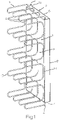
- the invention comprises a drying device which has a mounting panel 1 and electrically heated drying hangers 2 arranged on it.
- the drying hangers 2 extend from the top edge 3 to the bottom edge 4 of the mounting panel 1.
- the mounting panel 1 has a front wall 5 and upper and lower wall elements 6, 7 angled at the lower edge 4 and upper edge 3 thereof.
- the mounting panel 1 is closed laterally by the side walls 8 .
- the mounting panel 1 with the drying hangers 2 can be fastened, for example, to a wall or to another supporting structure that is not shown here.
- the upper and lower wall elements 6, 7 (see 3 ) have receiving holes 9, 10 for receiving end pieces 11, 12 of the drying hanger 2 on both sides.
- the upper receiving holes 9 are arranged in the upper wall element 6 and receive the upper end pieces 11 of the drying hangers 2 .
- the lower receiving holes 10 take on the lower end pieces 12 of the drying hanger 2.
- the drying hangers 2 have hanger sections 13 bent forwards in a known manner and sections 14 resting against the front wall 5 .
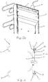
- the Figure 2a shows the back of the drying device.
- the upper end pieces 11 of the drying hangers 2 protrude through the upper mounting holes 9 through the upper wall element 6 .
- the electrical lines are drawn through the upper end pieces 11, namely the electrical supply lines 15 and the heating lines 16.
- the drying hangers 2 are connected to the front wall 5 in the area of the adjoining sections 14 by means of fastening elements 17 in order to ensure permanent fastening.
- the fastening elements 17 can be welded as screw bolts, for example, to the adjacent sections 14 or be connected by means of clamp connections.
- the electrical lines 15, 16 are combined in a power connection box 18 and the power connection box 18 and its electrical lines are fed from a central power connection 19 with electricity.
- the figure 3 shows a longitudinal section through the mounting panel 1 in a broken representation. It clearly shows a feature that is essential to the invention, namely that an upper receiving hole 9 is provided in the upper wall element 6 , which allows the upper end piece 11 to be hung in the mounting panel 1 .
- the upper end piece 11 is fixed by means of a clamping device 20 so that it cannot slip out of the upper receiving hole 9 .
- the lower end piece 12 When assembling the drying device, for example, the lower end piece 12 can first be inserted into the associated lower receiving hole 10 and then the upper end piece 11 can be hung into the upper receiving hole 9 in a simple manner.
- the electrical supply line 15 and the heating line 16 can easily be threaded through the upper receiving hole 9 beforehand.
- the clamping device 20 z. B. in the form of a pipe clamp at the upper end piece 11, as in the figure 3 is shown. Assembly is facilitated by the fact that the drying hanger 2 is flexible in the longitudinal direction with regard to the plurality of bent hanger sections 13, so that it can be hung in easily.
- the fastening elements 17 are screw bolts here, which are connected to the adjacent sections 14 of the drying hanger 2, for example by welding.
- the bolts can be inserted through associated holes in the front wall 5 of the mounting panel 1 and tightened from the back with a nut.
- the arrangement of two fastening elements 17 per adjacent section is only an example.
- a single fastening element 17 per adjoining section 14 or one fastening element for every second adjoining section 14 can also suffice.
- the Figure 2b shows broken off the rear view of the mounting panel 1 with the arrangement of a partial cover 21 of the back of the mounting panel 1 to cover the electrical connections and to protect against unauthorized access. It is also possible to clad the entire back of the mounting panel 1, which can be useful if the drying device is not arranged on a closed wall but on a mounting frame.
Landscapes
- Engineering & Computer Science (AREA)
- Textile Engineering (AREA)
- Drying Of Solid Materials (AREA)
Applications Claiming Priority (1)
| Application Number | Priority Date | Filing Date | Title |
|---|---|---|---|
| ATA50903/2020A AT524359A1 (de) | 2020-10-21 | 2020-10-21 | Trockenvorrichtung |
Publications (1)
| Publication Number | Publication Date |
|---|---|
| EP3988005A1 true EP3988005A1 (fr) | 2022-04-27 |
Family
ID=78087252
Family Applications (1)
| Application Number | Title | Priority Date | Filing Date |
|---|---|---|---|
| EP21202058.0A Withdrawn EP3988005A1 (fr) | 2020-10-21 | 2021-10-12 | Dispositif de séchage |
Country Status (2)
| Country | Link |
|---|---|
| EP (1) | EP3988005A1 (fr) |
| AT (1) | AT524359A1 (fr) |
Citations (2)
| Publication number | Priority date | Publication date | Assignee | Title |
|---|---|---|---|---|
| EP0243342A1 (fr) * | 1986-04-22 | 1987-10-28 | Helmut Jannach | Dispositif pour le séchage de chaussures et chaussures de ski ou similaires |
| US5692316A (en) * | 1996-03-07 | 1997-12-02 | Antal; Christopher P. | Apparel drying rack apparatus for boots and gloves |
Family Cites Families (1)
| Publication number | Priority date | Publication date | Assignee | Title |
|---|---|---|---|---|
| WO1997031565A1 (fr) * | 1996-03-01 | 1997-09-04 | Helmut Jannach | Dispositif pour le sechage des chaussures |
-
2020
- 2020-10-21 AT ATA50903/2020A patent/AT524359A1/de not_active Application Discontinuation
-
2021
- 2021-10-12 EP EP21202058.0A patent/EP3988005A1/fr not_active Withdrawn
Patent Citations (2)
| Publication number | Priority date | Publication date | Assignee | Title |
|---|---|---|---|---|
| EP0243342A1 (fr) * | 1986-04-22 | 1987-10-28 | Helmut Jannach | Dispositif pour le séchage de chaussures et chaussures de ski ou similaires |
| US5692316A (en) * | 1996-03-07 | 1997-12-02 | Antal; Christopher P. | Apparel drying rack apparatus for boots and gloves |
Also Published As
| Publication number | Publication date |
|---|---|
| AT524359A1 (de) | 2022-05-15 |
Similar Documents
| Publication | Publication Date | Title |
|---|---|---|
| DE19712362C1 (de) | Vorrichtung zum Befestigen einer Tragschiene an Rahmenschenkeln und Montageplatten eines Schaltschrankes | |
| DE69924526T2 (de) | Schrank | |
| DE202019101428U1 (de) | Kabelrinne, Schutzleiterhalter dafür sowie Schutzleiterset | |
| DE10001185C1 (de) | Vorrichtung zum Befestigen einer Traschiene an Rahmenschenkeln eines Schaltschrank-Rahmengestelles | |
| WO2021148671A1 (fr) | Dispositif de liaison, système structural et étagère | |
| DE1765911B1 (de) | Kabelhalterung zur Verwendung in Trennwanddurchfuehrungen | |
| DE102018124484A1 (de) | Anschlussleiste für elektrische oder elektronische Geräte an einem Schrank | |
| EP3988005A1 (fr) | Dispositif de séchage | |
| DE2327078A1 (de) | Stromverteilerschiene fuer stromabnehmer, insbesondere adapter | |
| DE1949694C3 (de) | Unterirdisch angeordneter Niederspannungsverteiler | |
| EP1984582B1 (fr) | Plafond intérieur suspendu et éléments composant celui-ci | |
| DE3106310A1 (de) | Moebelsystem fuer den zusammenbau von kastenmoebel | |
| DE3718823C2 (fr) | ||
| EP4150725B1 (fr) | Boîtier de fixation pour connecteur mâle haute performance | |
| DE3317799C3 (de) | Tragvorrichtung für Elektrokabel | |
| DE102007008873B4 (de) | Gehäusesystem | |
| DE1905735A1 (de) | Abhaengbare Deckenkonstruktion | |
| DE7522691U (de) | Lichtleiste | |
| DE19956951C2 (de) | Arbeitsplatzmöbel mit einem Möbelgestell aus vertikalen Säulen und Quertraversen | |
| DE752837C (de) | Zaehler- oder Verteilungstafel aus Isolierpressstoff fuer elektrische Hausstromnetzeod. dgl. | |
| DE2734415C2 (fr) | ||
| EP3499660B1 (fr) | Agencement comprenant un premier et un second rails support, un couvercle et un premier et un second dispositifs support, et boîtier de distribution | |
| DE4426791A1 (de) | Vorrichtung mit Lamellen, insbesondere mit Metallamellen zur einhakbaren, eine Ummantelungsfläche bildenden Verkleidung | |
| DE1591623C (de) | Schrank fur Gerate der Nachrichten techmk | |
| DE202022100718U1 (de) | Haltevorrichtung für eine Sicherungsbaugruppe |
Legal Events
| Date | Code | Title | Description |
|---|---|---|---|
| PUAI | Public reference made under article 153(3) epc to a published international application that has entered the european phase |
Free format text: ORIGINAL CODE: 0009012 |
|
| STAA | Information on the status of an ep patent application or granted ep patent |
Free format text: STATUS: THE APPLICATION HAS BEEN PUBLISHED |
|
| AK | Designated contracting states |
Kind code of ref document: A1 Designated state(s): AL AT BE BG CH CY CZ DE DK EE ES FI FR GB GR HR HU IE IS IT LI LT LU LV MC MK MT NL NO PL PT RO RS SE SI SK SM TR |
|
| STAA | Information on the status of an ep patent application or granted ep patent |
Free format text: STATUS: REQUEST FOR EXAMINATION WAS MADE |
|
| 17P | Request for examination filed |
Effective date: 20221024 |
|
| RBV | Designated contracting states (corrected) |
Designated state(s): AL AT BE BG CH CY CZ DE DK EE ES FI FR GB GR HR HU IE IS IT LI LT LU LV MC MK MT NL NO PL PT RO RS SE SI SK SM TR |
|
| STAA | Information on the status of an ep patent application or granted ep patent |
Free format text: STATUS: THE APPLICATION IS DEEMED TO BE WITHDRAWN |
|
| 18D | Application deemed to be withdrawn |
Effective date: 20240501 |