EP3988903A1 - Position sensor system - Google Patents
Position sensor system Download PDFInfo
- Publication number
- EP3988903A1 EP3988903A1 EP21190602.9A EP21190602A EP3988903A1 EP 3988903 A1 EP3988903 A1 EP 3988903A1 EP 21190602 A EP21190602 A EP 21190602A EP 3988903 A1 EP3988903 A1 EP 3988903A1
- Authority
- EP
- European Patent Office
- Prior art keywords
- receiver
- position sensor
- sensor system
- receiver coil
- coil
- Prior art date
- Legal status (The legal status is an assumption and is not a legal conclusion. Google has not performed a legal analysis and makes no representation as to the accuracy of the status listed.)
- Pending
Links
Images







Classifications
-
- G—PHYSICS
- G01—MEASURING; TESTING
- G01D—MEASURING NOT SPECIALLY ADAPTED FOR A SPECIFIC VARIABLE; ARRANGEMENTS FOR MEASURING TWO OR MORE VARIABLES NOT COVERED IN A SINGLE OTHER SUBCLASS; TARIFF METERING APPARATUS; MEASURING OR TESTING NOT OTHERWISE PROVIDED FOR
- G01D5/00—Mechanical means for transferring the output of a sensing member; Means for converting the output of a sensing member to another variable where the form or nature of the sensing member does not constrain the means for converting; Transducers not specially adapted for a specific variable
- G01D5/12—Mechanical means for transferring the output of a sensing member; Means for converting the output of a sensing member to another variable where the form or nature of the sensing member does not constrain the means for converting; Transducers not specially adapted for a specific variable using electric or magnetic means
- G01D5/14—Mechanical means for transferring the output of a sensing member; Means for converting the output of a sensing member to another variable where the form or nature of the sensing member does not constrain the means for converting; Transducers not specially adapted for a specific variable using electric or magnetic means influencing the magnitude of a current or voltage
- G01D5/20—Mechanical means for transferring the output of a sensing member; Means for converting the output of a sensing member to another variable where the form or nature of the sensing member does not constrain the means for converting; Transducers not specially adapted for a specific variable using electric or magnetic means influencing the magnitude of a current or voltage by varying inductance, e.g. by a movable armature
- G01D5/204—Mechanical means for transferring the output of a sensing member; Means for converting the output of a sensing member to another variable where the form or nature of the sensing member does not constrain the means for converting; Transducers not specially adapted for a specific variable using electric or magnetic means influencing the magnitude of a current or voltage by varying inductance, e.g. by a movable armature by influencing the mutual induction between two or more coils
-
- G—PHYSICS
- G01—MEASURING; TESTING
- G01D—MEASURING NOT SPECIALLY ADAPTED FOR A SPECIFIC VARIABLE; ARRANGEMENTS FOR MEASURING TWO OR MORE VARIABLES NOT COVERED IN A SINGLE OTHER SUBCLASS; TARIFF METERING APPARATUS; MEASURING OR TESTING NOT OTHERWISE PROVIDED FOR
- G01D5/00—Mechanical means for transferring the output of a sensing member; Means for converting the output of a sensing member to another variable where the form or nature of the sensing member does not constrain the means for converting; Transducers not specially adapted for a specific variable
- G01D5/12—Mechanical means for transferring the output of a sensing member; Means for converting the output of a sensing member to another variable where the form or nature of the sensing member does not constrain the means for converting; Transducers not specially adapted for a specific variable using electric or magnetic means
- G01D5/14—Mechanical means for transferring the output of a sensing member; Means for converting the output of a sensing member to another variable where the form or nature of the sensing member does not constrain the means for converting; Transducers not specially adapted for a specific variable using electric or magnetic means influencing the magnitude of a current or voltage
- G01D5/20—Mechanical means for transferring the output of a sensing member; Means for converting the output of a sensing member to another variable where the form or nature of the sensing member does not constrain the means for converting; Transducers not specially adapted for a specific variable using electric or magnetic means influencing the magnitude of a current or voltage by varying inductance, e.g. by a movable armature
- G01D5/204—Mechanical means for transferring the output of a sensing member; Means for converting the output of a sensing member to another variable where the form or nature of the sensing member does not constrain the means for converting; Transducers not specially adapted for a specific variable using electric or magnetic means influencing the magnitude of a current or voltage by varying inductance, e.g. by a movable armature by influencing the mutual induction between two or more coils
- G01D5/2073—Mechanical means for transferring the output of a sensing member; Means for converting the output of a sensing member to another variable where the form or nature of the sensing member does not constrain the means for converting; Transducers not specially adapted for a specific variable using electric or magnetic means influencing the magnitude of a current or voltage by varying inductance, e.g. by a movable armature by influencing the mutual induction between two or more coils by movement of a single coil with respect to two or more coils
-
- G—PHYSICS
- G01—MEASURING; TESTING
- G01D—MEASURING NOT SPECIALLY ADAPTED FOR A SPECIFIC VARIABLE; ARRANGEMENTS FOR MEASURING TWO OR MORE VARIABLES NOT COVERED IN A SINGLE OTHER SUBCLASS; TARIFF METERING APPARATUS; MEASURING OR TESTING NOT OTHERWISE PROVIDED FOR
- G01D5/00—Mechanical means for transferring the output of a sensing member; Means for converting the output of a sensing member to another variable where the form or nature of the sensing member does not constrain the means for converting; Transducers not specially adapted for a specific variable
- G01D5/12—Mechanical means for transferring the output of a sensing member; Means for converting the output of a sensing member to another variable where the form or nature of the sensing member does not constrain the means for converting; Transducers not specially adapted for a specific variable using electric or magnetic means
- G01D5/14—Mechanical means for transferring the output of a sensing member; Means for converting the output of a sensing member to another variable where the form or nature of the sensing member does not constrain the means for converting; Transducers not specially adapted for a specific variable using electric or magnetic means influencing the magnitude of a current or voltage
- G01D5/20—Mechanical means for transferring the output of a sensing member; Means for converting the output of a sensing member to another variable where the form or nature of the sensing member does not constrain the means for converting; Transducers not specially adapted for a specific variable using electric or magnetic means influencing the magnitude of a current or voltage by varying inductance, e.g. by a movable armature
-
- G—PHYSICS
- G01—MEASURING; TESTING
- G01D—MEASURING NOT SPECIALLY ADAPTED FOR A SPECIFIC VARIABLE; ARRANGEMENTS FOR MEASURING TWO OR MORE VARIABLES NOT COVERED IN A SINGLE OTHER SUBCLASS; TARIFF METERING APPARATUS; MEASURING OR TESTING NOT OTHERWISE PROVIDED FOR
- G01D5/00—Mechanical means for transferring the output of a sensing member; Means for converting the output of a sensing member to another variable where the form or nature of the sensing member does not constrain the means for converting; Transducers not specially adapted for a specific variable
- G01D5/12—Mechanical means for transferring the output of a sensing member; Means for converting the output of a sensing member to another variable where the form or nature of the sensing member does not constrain the means for converting; Transducers not specially adapted for a specific variable using electric or magnetic means
- G01D5/14—Mechanical means for transferring the output of a sensing member; Means for converting the output of a sensing member to another variable where the form or nature of the sensing member does not constrain the means for converting; Transducers not specially adapted for a specific variable using electric or magnetic means influencing the magnitude of a current or voltage
- G01D5/20—Mechanical means for transferring the output of a sensing member; Means for converting the output of a sensing member to another variable where the form or nature of the sensing member does not constrain the means for converting; Transducers not specially adapted for a specific variable using electric or magnetic means influencing the magnitude of a current or voltage by varying inductance, e.g. by a movable armature
- G01D5/204—Mechanical means for transferring the output of a sensing member; Means for converting the output of a sensing member to another variable where the form or nature of the sensing member does not constrain the means for converting; Transducers not specially adapted for a specific variable using electric or magnetic means influencing the magnitude of a current or voltage by varying inductance, e.g. by a movable armature by influencing the mutual induction between two or more coils
- G01D5/2086—Mechanical means for transferring the output of a sensing member; Means for converting the output of a sensing member to another variable where the form or nature of the sensing member does not constrain the means for converting; Transducers not specially adapted for a specific variable using electric or magnetic means influencing the magnitude of a current or voltage by varying inductance, e.g. by a movable armature by influencing the mutual induction between two or more coils by movement of two or more coils with respect to two or more other coils
Definitions
- the invention relates to a position sensor system, particularly an inductive position sensor system.
- This patent proposal is particularly describing a specific setup of an inductive position sensor system allowing measurement of one or more physical quantities of same or different types by using a coil set of two or more independent receiver coils and one or more transmitter coils.
- Inductive position sensors implement a magnet-free technology, utilizing the physical principles of eddy currents or inductive coupling to detect the position of a target that is moving above a set of coils, consisting for example of one transmitter coil and two receiver coils, particularly a sine receiver coil and a cosine receiver coil.
- the three coils, one transmitter coil and two receiver coils are typically provided as copper traces on a printed circuit board (PCB). They are arranged such that the transmitter coil induces a secondary voltage in the two receiver coils, which depends on the position of the metallic target above the coils.
- PCB printed circuit board
- a signal representative of the target's position over the coils is obtained by demodulating and processing the secondary voltages from the receiver coils.
- the target can be any kind of metal, such as aluminum, steel, or a printed circuit board (PCB) with a printed copper layer.
- PCB printed circuit board
- an inductive sensor system comprises a metallic target.
- the inductive sensor system may use different types of targets, such as wire loops or passive resonant circuits comprised of inductances and capacitors.
- inductive sensor systems comprise two receiver coils per sensor, particularly a sine receiver coil and a cosine receiver coil.
- Other embodiments of inductive sensor systems may be using three receiver coils instead of two for each sensor.
- these coils can be designed for linear, arc or rotary motion.
- the inductive sensor systems known from the art have a single set of receiver coils and one transmitter coil.
- An oscillator generates a radio-frequency signal, which is applied to the transmitter coil to create a high frequency magnetic field.
- This high frequency magnetic field is picked up by the receiver coils, particularly the sine receiver coil and the cosine receiver coil.
- the secondary voltage picked up by the receiver coils is changing in amplitude and phase, allowing the determination of the target's position by analysing these effects.
- a signal representative of the target's position over the coils is available in digital format and fed to the output interface.
- Typical types of output interfaces include, but are not limited to:
- This invention relates to position sensor systems, particularly inductive position sensor systems, with high functional safety requirement and need for redundancy requiring a small chip size for implementation.
- the position sensor system particularly inductive position sensor system, according to the invention comprises at least two receiver coil sets, at least one transmitter coil and a signal conditioning and processing unit,
- An integrated circuit according to the invention is a set of electronic circuits on one small flat piece of semiconductor material, also referred to as silicone chip. Such integrated circuits are often contained in packages with connecting pins for connecting the integrated circuit to other electronic circuits, which are for example arranged on a printed circuit board (PCB).
- PCB printed circuit board
- the signal conditioning and processing unit for the at least two receiver coil sets and the at least one transmitter coil is contained in a single integrated circuit. Furthermore, the at least two receiver coil sets, the at least one transmitter coil and the integrated circuit containing the signal conditioning and processing unit are located on a single printed circuit board. Thereby, the required chip size is reduced, while still providing redundant receiver coil sets required by a high functional safety system.
- the signal conditioning and processing unit comprises a separate receiver channel for each receiver coil set or a shared receiver channel and a multiplexer for multiplexing the at least two receiver coil sets sequentially to the shared receiver channel.
- a separate receiver channel for each set of receiver coils provides faster signal processing due to the parallel processing of the signals from the receiver coil sets, while a shared receiver channel with a multiplexer for multiplexing the at least two receiver coil sets sequentially to the shared receiver channel requires less chip size.
- each receiver channel comprises a radio-frequency signal receiver and processor, an analog-to-digital converter and a digital signal processor.
- the signal conditioning and processing unit comprises an oscillator for generating a radio-frequency signal for the at least one transmitter coil.
- the position sensor system can comprise a shared transmitter coil for the at least two receiver coil sets, which is connected to the oscillator of the signal conditioning and processing unit.
- the position sensor system can comprise separate transmitter coils for the at least two receiver coil sets, wherein the separate receiver coil sets are connected in series or parallel to the oscillator of the signal conditioning and processing unit.
- the signal conditioning and processing unit has a common output, particularly for providing a combined output signal information for all receiver coil sets respectively all receiver channels of the signal conditioning and processing unit.
- the position sensor system comprises at least one moving target, particularly at least one metallic moving target or any other target structure that is modifying the electromagnetic field of the at least of transmitter coil.
- the position sensor system can be manufactured and sold without the moving target and only cooperates with the metallic target once used for its intended purpose.
- the metallic target and the position sensor system are adapted to each other, so that the position sensor system can securely determine the position of the metallic target.
- the inductive position sensor system according to the invention is for example a linear, arc or rotary motion sensor.
- the at least one transmitter coil is arranged outside the at least two receiver coil sets, particularly at the outer circumference of the at least two receiver coil sets, or inside a blank space provided by the at least two receiver coil sets.
- the position sensor system generates a high-resolution position signal from the at least two receiver coil sets or a differential signal from the at least two receiver coil sets.
- the position sensor system provides information for all receiver coil sets by means of an output interface, such as, but not limited to analog voltage, current modulation, PSI-5, Pulse width modulation (PWM), Single Edge Nibble Transmission Protocol (SENT), I2C protocol, Serial Peripheral Interface (SPI), Universal Asynchronous Receiver Transmitter (UART), CAN, or LIN.
- an output interface such as, but not limited to analog voltage, current modulation, PSI-5, Pulse width modulation (PWM), Single Edge Nibble Transmission Protocol (SENT), I2C protocol, Serial Peripheral Interface (SPI), Universal Asynchronous Receiver Transmitter (UART), CAN, or LIN.
- the position output accuracy can be improved by using additional coil inputs for determining disturbing quantities and compensating for these.
- Fig. 1 shows a first embodiment of a position sensor system 1 according to the prior art.
- the position sensor system 1 shown in Fig. 1 is an inductive position sensor system comprising a receiver coil set 2, 3, a transmitter coil 4 and a signal conditioning and processing unit 5.
- the receiver coil set 2, 3 of the inductive position sensor 1 of Fig. 1 comprises a sine receiver coil 2 and a separate cosine receiver coil 3.
- the signal conditioning and processing unit 5 is contained in an integrated circuit 6.
- the position sensor system 1 implements a magnet-free technology, utilizing the physical principles of eddy currents or inductive coupling to detect the position of a target 8 that is moving above a set of coils 2, 3, 4, consisting for example of one transmitter coil 4 and two receiver coils 2, 3 as shown in Fig. 1 .
- Fig. 2 shows a practical implementation of the position sensor system 1 shown in Fig. 1 , particularly for detecting rotary motion.
- the three coils 2, 3, 4, namely the one transmitter coil 4 and two receiver coils 2, 3 are typically provided as copper traces on a printed circuit board 7. They are arranged such that the transmitter coil 4 induces a secondary voltage in the two receiver coils 2, 3, which depends on the position of the metallic target 8 above the coils 2, 3, 4.
- the signal conditioning and processing unit 5 is located on the same printed circuit board 7 as the three coils 2, 3, 4.
- the target 8 is mounted to a rotating shaft 9, which rotary motion should be detected.
- a signal representative of the target's 8 position over the coils 2, 3, 4 is obtained by demodulating and processing the secondary voltages from the receiver coils 2, 3.
- the target 8 can be any kind of metal, such as aluminum, steel, or a PCB with a printed copper layer.
- This invention depicts an inductive sensor system 1 comprising of a metallic target 8.
- Other embodiments of inductive sensor systems 1 for which this invention can also be applied may use different types of targets 8, such as wire loops or passive resonant circuits comprised of inductances and capacitors.
- Fig. 3 shows a second embodiment of a position sensor according to the prior art.
- the position sensor comprises a sine receiver coil 2 and a cosine receiver coil 3, each having one positive and one negative period.
- the sine receiver coil 2 and the cosine receiver coil 4 are surrounded a transmitter coil 4.
- the coils 2, 3, 4 are arranged along a linear path to detect a linear motion of the target 8.
- Fig. 4 shows a third embodiment of a position sensor according to the prior art.
- the third embodiment of Fig. 4 differs from the second embodiment of Fig. 3 in that the coils 2, 3, 4 are arranged circularly for detecting a rotary motion of target 8.
- Fig. 5 to 8 show fourth to seventh embodiments of position sensor system 1 according to the prior art.
- Each position sensor system 1 of the fourth to seventh embodiment comprises a sine receiver coil, a cosine receiver coil 3 and a transmitter coil.
- the signals of the receiver coils 2, 3 are processed by a signal conditioning and processing unit 5, which is contained in an integrated circuit 6.
- Fig. 8 are designed for detecting rotary motion of one or more targets 8.
- the sine receiver coil 2 and the cosine receiver coil 3 each have one or more positive periods and one or more negative periods.
- the fourth to seventh embodiment differ in the number of periods and number of targets.
- the sine receiver coil 2 and the cosine receiver coil 3 each have one positive period and one negative period, while the motion of a single target 8 is detected.
- the sine receiver coil 2 and the cosine receiver coil 3 each have two positive periods and two negative periods, while the motion of two targets 8 are detected.
- the sine receiver coil 2 and the cosine receiver coil 3 each have four positive periods and four negative periods, while the motion of four targets 8 are detected.
- the sine receiver coil 2 and the cosine receiver coil 3 each have three positive periods and three negative periods, while the motion of three targets 8 are detected.
- the coils 2, 3, 4 can be designed for linear, arc or rotary motion.
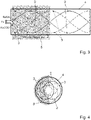
- a coil design for a linear motion sensor is shown in Fig. 3 and examples of rotary coil designs having different numbers of phases per turn are shown in Fig. 4 to Fig. 8 .
- Fig. 9 shows an eighth embodiment of a position sensor system 1 according to the prior art. Shown in Fig. 9 is the block diagram of a position sensor system 1 having a single set of receiver coils 2, 3 and one transmitter coil 4. An oscillator 10 of the signal conditioning and processing unit 5 generates an RF signal, which creates a high frequency magnetic field by the transmitter coil 4, which is picked up by the receiver coils 2, 3 with terminals R1N/R1P and R2N/R2P. Depending on the position of the metallic target 8 over the coils 2, 3, 4, the secondary voltage picked up by the receiver coils 2, 3 is changing in amplitude and phase, allowing the determination of the target's position by analysing these effects.
- the receiver signals are demodulated and amplified, then converted to a digital signal by an A-D converter 11 and further processed in the digital signal processor 12, like being converted from sine and cosine signals into an angle representation by means of a CORDIC algorithm, transforming rectangular coordinates to polar coordinates.
- ⁇ arctan V SIN V COS
- a signal representative of the target's position over the coils 2, 3, 4 is available in digital format and fed to the output interface 13.
- Fig. 10 shows a first embodiment of a system 1 using two position sensors 1 according to the prior art.
- FIG. 11 shows a second embodiment of a system 1 using two position sensors 1 according to the prior art.
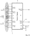
- Fig. 12 shows a first embodiment of a position sensor system 1 according to the invention.
- This invention is targeting systems with high functional safety requirement and need for redundancy by implementing the signal processing of two or more sets of receiver coils 2, 3 with one or more transmitter coils 4 on the same on the same printed circuit board 7 while the receiver coils 2, 3 sensing elements are fully redundant and physically separated.
- An outline of such implementation having two sets of receiver coils 2, 3 is shown in Fig. 12 . In other embodiments of this configuration, three or more sets of receiver coils 2, 3 can be implemented.
- the position sensor system 1 of Fig. 12 is an inductive position sensor system, comprising two receiver coil sets 2, 3, one transmitter coil 4 and a signal conditioning and processing unit 5.
- Each receiver coil set comprises a sine receiver coil 2 and a cosine receiver coil 3.
- the signal conditioning and processing unit 5 is contained in a single integrated circuit 6 and that the at least two receiver coil sets 2, 3, the transmitter coil 4 and the integrated circuit 6 containing the signal conditioning and processing unit 5 are located on a single printed circuit board 7.
- each receiver (Receiver #1 and Receiver #2 in Fig. 12 ) can be used for detecting both the same or independent moving target elements 8 and they share one or more transmitter coils 4 on the same chip.
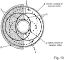
- Fig. 13 shows a second embodiment of a position sensor system 1 according to the invention.
- Fig. 13 particularly refers to the position of the transmitter coil 4 with respect to the at least two receiver coil sets 2, 3.
- the transmitter coil 4 can be placed outside the at least two receiver coil sets 2, 3, particularly at the outer circumference of the receiver coil sets 2, 3, as shown in Fig. 13 .
- Other embodiments of this invention may have the transmitter coil 4 placed inside a blank space provided by the receiver coil sets 2, 3, as also shown in Fig. 13 .
- Fig. 14 shows a third embodiment of a position sensor system 1 according to the invention
- Fig. 15 a fourth embodiment of a position sensor system 1 according to the invention
- Fig. 16 a fifth embodiment of a position sensor system 1 according to the invention.
- Each of these position sensor systems 1 shown in Figs. 14 to 16 comprises two receiver coil sets 2, 3, each receiver coil set 2, 3 comprising a sine receiver coil 2 and a cosine receiver coil 3.
- Connectors of the sine receiver coils of the two coil receiver coil sets are labelled R1N/R1P respectively R3N/R3P and connectors of the cosine receiver coils of the two receiver coil sets 2, 3 are labelled R2N/R2P respectively R4N/R4P.
- Each receiver coil set 2, 3 detects a different target 8.
- each position sensor systems 1 shown in Figs. 14 to 16 comprise two transmitter coils 4 and a single signal conditioning and processing unit 5.
- the two transmitter coils 4 are connected in series and are fed by the same oscillator 10 of the signal conditioning and processing unit 5.
- the fourth embodiment shown in Fig. 15 the two transmitter coils 4 are connected in parallel and are fed by the same oscillator 10 of the signal conditioning and processing unit 5.
- the fifth embodiment shown in Fig. 16 the two transmitter coils 4 are separated from each other and are fed by independent oscillators 10 of the signal conditioning and processing unit 5.
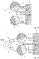
- FIG. 14 to Fig. 16 A practical implementation of the configuration shown in Fig. 14 to Fig. 16 could be a multiturn sensor having a primary wheel and two attached secondary wheels, each having a slightly different transmission ratio relative to the primary wheel.
- a metallic target 8 is attached to each of the secondary wheels, each target is detected independently by receiver coil sets #1 and #2, respectively.
- Such a sixth embodiment based on the position sensor 1 of Fig. 14 is shown in Fig. 17 .
- the innovative aspect of this example is to use a single integrated circuit having two sets of receiver coils 2, 3 instead of using one position sensor 1 for each secondary wheel.
- a seventh embodiment utilizing two receiver coil sets 2, 3 and one transmitter coil 4 shown in Fig. 18 is a dual receiver coil setup example for creating a long stroke Vernier design using 3 periods on coil set 1 (R1N, R1P, R2N, R2P) and 4 periods on coil set 2 (R3N, R3P, R4N, R4P).
- the receiver coil sets #1 and #2 may be placed next to each other (as shown in Fig. 18 ) or placed on top of each other.
- Fig. 19 outlines the sensor outputs of the circuit shown in Fig. 18 , using 3 phases for Sensor 1 (receiver coils R1,R2) and 4 phases for Sensor 2 (receiver coils R3,R4).
- each sensor has 12-bits resolution (4096 steps per phase).
- the first receiver coil set 2, 3 is using 4 periods per full stroke length, while the second receiver coil set 2, 3 is using 1 period per full stroke length. This configuration allows an increase of resolution by a factor of four, respectively by the number of phases of coil set #1.
- the period on coil set #1 over which the target 8 is moving can be determined and thus, an unambiguous, high-resolution position detection is possible, providing an absolute position with 16384 positions over the full stroke length.
- Other embodiments of the same implementation may use different resolutions than 4096 steps per period.
- the embodiment of Fig. 20 may be placing coil sets #1 and #2 next to each other or on top of each other.
- the signal conditioning and processing unit 5 is contained in a single integrated circuit 6 and that the at least two receiver coil sets 2, 3, the at least one transmitter coil 4 and the integrated circuit 6 containing the signal conditioning and processing unit 5 are located on a single printed circuit board 7.
- Fig. 21 shows a nineth embodiment of a position sensor system 1 according to the invention and Fig. 22 shows a tenth embodiment of a position sensor system 1 according to the invention.
- Figs. 21 and 22 Shown in Figs. 21 and 22 are two possible implementations of a multi-receiver coil set position sensor 1 on a single chip.
- two sets of receiver coils 2, 3 are processed sequentially, selected by a multiplexer 14 at the RF front-end block.
- This set-up requires fewer building blocks, as it utilizes the same chain of signal processing, following the multiplexer (MUX) for both receiver coil sets.
- MUX multiplexer
- This embodiment is also referred to as having a shared receiver channel.
- the multiplexer 14 is for multiplexing the at least two receiver coil sets 2, 3 sequentially to the shared receiver channel.
- This principle may be applied to more than two receiver coil sets 2, 3.
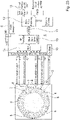
- Fig. 22 the two sets of receiver coils 2, 3 are processed in parallel receiver channels, essentially doubling the processing speed. This setup is particularly useful for applications requiring fast data rates and low or no signal delay between each receiver coil set.
- Each receiver channel comprises a radio-frequency signal receiver and processor 15, an analog-to-digital converter 11 and a digital signal processor 12.
- the signal-processing unit 12 converts the input voltages into digital values. Offsets and amplitude mismatch of these signals is compensated. The angle information is calculated based on the compensated input data and the phase shift between the two coil sets 2, 3 is digitally removed.
- Fig. 23 shows an eleventh embodiment of a position sensor system 1 according to the invention.
- the output accuracy can be improved by:
- the system availability can improve by:
- Another example for such implementation is a steering sensor with the requirement for a high-resolution angle output, being absolute within one turn and provides high diagnostic coverage. It is based on the same principle as the circuit shown in Fig. 20 for a linear motion sensor.
- one receiver coil set is designed for 1 period per mechanical turn, while the second receiver coil set is designed for 8 periods per mechanical turn.
- three or more sets of receiver coils can be implemented.
- Each receiver (Receiver #1 and Receiver #2 in Fig. 12 ) can be used for detecting both the same or independent moving target elements and they share one or more transmitter coils on the same chip.
- the transmitter coil can be placed at the outer circumference of the receiver coil set, as shown in Fig. 13 , green circle.
- Receiver coil set #1, R1N/R1P and R2N/R2P as well as receiver coil set #2, R3N/R3P and R4N/R4P detect different targets, but share the same transmitter coil; the two transmitter coil sections are connected in series and are fed by the same oscillator.
- the two transmitter coil sections may be connected in parallel are fed by the same oscillator as shown in Fig. 15
- a practical implementation of the configuration shown in Fig. 14 to Fig. 16 could be a multiturn sensor having a primary wheel and two attached secondary wheels, each having a slightly different transmission ratio relative to the primary wheel.
- a metallic target is attached to each of the secondary wheels, each target is detected independently by receiver coil sets #1 and #2, respectively.
- Such embodiment is shown in Fig. 17 .
- the innovative aspect of this example is to use a single IC having two sets of receiver coils instead of using one position sensor for each secondary wheel.
- FIG. 18 Another embodiment utilizing two receiver coils and one transmitter coils shown in Fig. 18 is a dual receiver coil setup example for creating a long stroke Vernier design using 3 periods on coil set 1 (R1N, RIP, R2N, R2P) and 4 periods on coil set 2 (R3N, R3P, R4N, R4P).
- the receiver coil sets #1 and #2 may be placed next to each other (as shown in Fig. 18 ) or placed on top of each other.
- Fig. 19 outlines the sensor outputs of the circuit shown in Fig. 18 , using 3 phases for Sensor 1 (receiver coils R1,R2) and 4 phases for Sensor 2 (receiver coils R3,R4).
- each sensor has 12-bits resolution (4096 steps per phase).
- the first receiver coil set 2, 3 is using 4 periods per full stroke length, while the second receiver coil set 2, 3 is using 1 period per full stroke length. This configuration allows an increase of resolution by a factor of four, respectively by the number of phases of coil set #1.
- the embodiment of Fig. 20 may be placing coil sets #1 and #2 next to each other or on top of each other.
- Figs. 21 and 22 Shown in Figs. 21 and 22 are two possible implementations of a multi-receiver coil set position sensor on a single chip.
- two sets of receiver coils are processed sequentially, selected by a multiplexer (MUX) at the RF front-end block.
- MUX multiplexer
- This set-up requires fewer building blocks, as it utilizes the same chain of signal processing, following the multiplexer (MUX) for both receiver coil sets.
- this principle may be applied to more than two receiver coil sets.
- Fig. 22 the two sets of receiver coils are processed in parallel channels, essentially doubling the processing speed. This setup is particularly useful for applications requiring fast data rates and low or no signal delay between each receiver coil set.
- the signal-processing unit converts the input voltages into digital values. Offsets and amplitude mismatch of these signals is compensated. The angle information is calculated based on the compensated input data and the phase shift between the two coil sets is digitally removed.
- the system availability can improve by:
- a twelfth embodiment of a position sensor system 1 refers to a steering sensor with the requirement for a high-resolution angle output, being absolute within one turn and provides high diagnostic coverage.
- one receiver coil set 2, 3 is designed for 1 period per mechanical turn, while the second receiver coil set 2, 3 is designed for 8 periods per mechanical turn.
- the target element 8 must be designed to generate sufficient signal amplitude for the absolute one-periodic as well as for the high-resolution sensor.
- Fig. 24 shows a configuration with eight output periods per one revolution which results in an eight times higher resolution compared to the single period absolute sensor. The accuracy can as well be improved this way depending on the mechanical setup and target 8 configuration.
- the diagnostic coverage can be increased by plausibility calculations of the two separate coil sets 2, 3.
- Some coil architectures may have benefits among others. For example, arc designs, mounted at the side of the shaft 9 require a relatively small area compared to full 360° shaped circular designs. In spite of such advantages, they show some disadvantages like reduced angle accuracy in case there is a displacement in radial direction.
- a second or third receiver coil set 2, 3, designed to measure radial displacement may be used to indicate and to compensate possible errors resulting from target 8 eccentricity.
- the present invention particularly refers to the following twelve aspects:
Landscapes
- Physics & Mathematics (AREA)
- General Physics & Mathematics (AREA)
- Transmission And Conversion Of Sensor Element Output (AREA)
- Measurement Of Length, Angles, Or The Like Using Electric Or Magnetic Means (AREA)
Priority Applications (4)
| Application Number | Priority Date | Filing Date | Title |
|---|---|---|---|
| CN202111182412.8A CN114383637A (zh) | 2020-10-22 | 2021-10-11 | 位置传感器系统 |
| US17/501,524 US20220128381A1 (en) | 2020-10-22 | 2021-10-14 | Position sensor system |
| JP2021172119A JP2022068860A (ja) | 2020-10-22 | 2021-10-21 | 位置センサシステム |
| US18/963,873 US20250093183A1 (en) | 2020-10-22 | 2024-11-29 | Position sensor system |
Applications Claiming Priority (1)
| Application Number | Priority Date | Filing Date | Title |
|---|---|---|---|
| EP20203390 | 2020-10-22 |
Publications (1)
| Publication Number | Publication Date |
|---|---|
| EP3988903A1 true EP3988903A1 (de) | 2022-04-27 |
Family
ID=73013278
Family Applications (1)
| Application Number | Title | Priority Date | Filing Date |
|---|---|---|---|
| EP21190602.9A Pending EP3988903A1 (de) | 2020-10-22 | 2021-08-10 | Position sensor system |
Country Status (4)
| Country | Link |
|---|---|
| US (2) | US20220128381A1 (de) |
| EP (1) | EP3988903A1 (de) |
| JP (1) | JP2022068860A (de) |
| CN (1) | CN114383637A (de) |
Cited By (3)
| Publication number | Priority date | Publication date | Assignee | Title |
|---|---|---|---|---|
| EP4293322A1 (de) * | 2022-06-17 | 2023-12-20 | Renesas Electronics America Inc. | Induktiver positionssensor zum detektieren einer linearen oder dreh- bewegung eines leitfähigen targets |
| EP4394331A1 (de) * | 2023-08-09 | 2024-07-03 | Melexis Technologies SA | Induktiver winkelsensor und induktiver drehmomentsensor |
| WO2025172737A1 (en) | 2024-02-15 | 2025-08-21 | Bosch Car Multimedia Portugal S.A | Inductive position sensor |
Families Citing this family (5)
| Publication number | Priority date | Publication date | Assignee | Title |
|---|---|---|---|---|
| DE102020216144A1 (de) * | 2020-12-17 | 2022-06-23 | Robert Bosch Gesellschaft mit beschränkter Haftung | Induktiver Positionssensor, Einrichtung |
| US12111187B2 (en) * | 2021-09-17 | 2024-10-08 | Sensata Technologies, Inc. | Inductive position sensor with coil configuration |
| KR20250021554A (ko) * | 2022-06-14 | 2025-02-13 | 오리엔탈모터가부시끼가이샤 | 유도형 위치 검출기 |
| US20250354833A1 (en) * | 2024-05-15 | 2025-11-20 | Schneider Electric Usa Inc. | Contact-less angular displacement measurement pcb system |
| CN120445272B (zh) * | 2025-07-14 | 2025-10-28 | 上海英达森斯半导体科技有限公司 | 基于非等周期线圈组信号校正方法及其应用 |
Citations (5)
| Publication number | Priority date | Publication date | Assignee | Title |
|---|---|---|---|---|
| US20040227644A1 (en) * | 2003-05-15 | 2004-11-18 | Yingjie Lin | Linear position sensor |
| WO2008032008A1 (en) * | 2006-09-14 | 2008-03-20 | Sagentia Limited | Position sensor |
| US20190310148A1 (en) | 2018-04-10 | 2019-10-10 | Semiconductor Components Industries, Llc | Inductive position sensor |
| WO2020171840A1 (en) * | 2019-02-21 | 2020-08-27 | Microsemi Corporation | Planar linear inductive position sensor having edge effect compensation |
| US20200278190A1 (en) * | 2019-03-01 | 2020-09-03 | Renesas Electronics America Inc. | Method for Increasing the Position Measurement Accuracy using Inductive Position Sensor |
Family Cites Families (11)
| Publication number | Priority date | Publication date | Assignee | Title |
|---|---|---|---|---|
| JPH0898486A (ja) * | 1994-09-26 | 1996-04-12 | Akira Ishizaki | 位置検出装置 |
| US6329813B1 (en) * | 1998-12-17 | 2001-12-11 | Mitutoyo Corporation | Reduced offset high accuracy induced current absolute position transducer |
| DE10158223B4 (de) * | 2001-11-16 | 2017-10-05 | Dr. Johannes Heidenhain Gmbh | Drehwinkel-Messgerät |
| US20070132449A1 (en) * | 2005-12-08 | 2007-06-14 | Madni Asad M | Multi-turn non-contact angular position sensor |
| DE102008015837A1 (de) * | 2008-03-27 | 2009-10-01 | Dr. Johannes Heidenhain Gmbh | Positionsmessgerät und Verfahren zu dessen Betrieb |
| GB2517152A (en) * | 2013-08-12 | 2015-02-18 | Gde Technology Ltd | Position sensor |
| DE102013218768A1 (de) * | 2013-09-19 | 2015-03-19 | Dr. Johannes Heidenhain Gmbh | Induktive Positionsmesseinrichtung |
| JP6480809B2 (ja) * | 2015-05-21 | 2019-03-13 | オークマ株式会社 | 多回転検出器 |
| DE102016202877B3 (de) * | 2016-02-24 | 2017-06-29 | Robert Bosch Gmbh | Drehwinkelsensor |
| DE102017211190A1 (de) * | 2017-06-30 | 2019-01-03 | Robert Bosch Gmbh | Sensorsystem zur Bestimmung mindestens einer Rotationseigenschaft eines rotierenden Elements |
| US11112274B2 (en) * | 2018-08-30 | 2021-09-07 | Integrated Device Technology, Inc. | Fully redundant position sensor |
-
2021
- 2021-08-10 EP EP21190602.9A patent/EP3988903A1/de active Pending
- 2021-10-11 CN CN202111182412.8A patent/CN114383637A/zh active Pending
- 2021-10-14 US US17/501,524 patent/US20220128381A1/en not_active Abandoned
- 2021-10-21 JP JP2021172119A patent/JP2022068860A/ja active Pending
-
2024
- 2024-11-29 US US18/963,873 patent/US20250093183A1/en active Pending
Patent Citations (5)
| Publication number | Priority date | Publication date | Assignee | Title |
|---|---|---|---|---|
| US20040227644A1 (en) * | 2003-05-15 | 2004-11-18 | Yingjie Lin | Linear position sensor |
| WO2008032008A1 (en) * | 2006-09-14 | 2008-03-20 | Sagentia Limited | Position sensor |
| US20190310148A1 (en) | 2018-04-10 | 2019-10-10 | Semiconductor Components Industries, Llc | Inductive position sensor |
| WO2020171840A1 (en) * | 2019-02-21 | 2020-08-27 | Microsemi Corporation | Planar linear inductive position sensor having edge effect compensation |
| US20200278190A1 (en) * | 2019-03-01 | 2020-09-03 | Renesas Electronics America Inc. | Method for Increasing the Position Measurement Accuracy using Inductive Position Sensor |
Cited By (4)
| Publication number | Priority date | Publication date | Assignee | Title |
|---|---|---|---|---|
| EP4293322A1 (de) * | 2022-06-17 | 2023-12-20 | Renesas Electronics America Inc. | Induktiver positionssensor zum detektieren einer linearen oder dreh- bewegung eines leitfähigen targets |
| EP4394331A1 (de) * | 2023-08-09 | 2024-07-03 | Melexis Technologies SA | Induktiver winkelsensor und induktiver drehmomentsensor |
| US12140486B1 (en) | 2023-08-09 | 2024-11-12 | Melexis Technologies Sa | Inductive angle sensor and inductive torque sensor |
| WO2025172737A1 (en) | 2024-02-15 | 2025-08-21 | Bosch Car Multimedia Portugal S.A | Inductive position sensor |
Also Published As
| Publication number | Publication date |
|---|---|
| CN114383637A (zh) | 2022-04-22 |
| US20220128381A1 (en) | 2022-04-28 |
| US20250093183A1 (en) | 2025-03-20 |
| JP2022068860A (ja) | 2022-05-10 |
Similar Documents
| Publication | Publication Date | Title |
|---|---|---|
| US20250093183A1 (en) | Position sensor system | |
| US11079291B2 (en) | Inductive position sensor | |
| US11598654B2 (en) | High resolution angular inductive sensor and associated method of use | |
| US6828783B2 (en) | Angle measuring instrument for a rotating shaft | |
| US10837848B2 (en) | Ultra-thin combined inductive torque and angle sensor for steering wheel position sensing | |
| CN116635696B (zh) | 高分辨率角感应传感器及相关联的使用方法 | |
| US12474154B2 (en) | Inductive position sensor comprising at least one transmit coil, an absolute position receive coil pair, a high-resolution position receive coil pair and a conductive moving target | |
| US7834616B2 (en) | Magnetic speed, direction, and/or movement extent sensor | |
| CN109883305B (zh) | 感应的位置测量装置 | |
| EP2006648A9 (de) | Rotationswinkelmesser | |
| CN102080998A (zh) | 用于求得转矩和用于索引识别的传感器装置 | |
| US20230152075A1 (en) | Radial inductive position sensor for detecting a rotational movement, high-resolution position sensor system and torque sensor system | |
| EP2881715B1 (de) | Selbstkalibrierender Positionssensor | |
| EP3147631B1 (de) | 360-grad-magnetdrehpositionssystem und verfahren zur berechnung eines hochpräzisen 360-grad-absolutdrehwinkels eines drehkörpers | |
| JP2010164553A (ja) | 低消費電流静電容量型検出装置 | |
| US20100148801A1 (en) | Capacitance-type encoder | |
| US20240077338A1 (en) | Inductive Sensor Arrangement for Detecting a Rotational Movement | |
| US11841248B2 (en) | Scanning element and inductive position measuring device having a scanning element | |
| EP1647816A1 (de) | Numerische Korrektur für ein kontaktloses Rotationswinkeldetektor und Drehmomentdetektor für eine Lenkvorrichtung | |
| US20250271250A1 (en) | Linear inductive position sensor | |
| EP3875913B1 (de) | Hybridpositionssensor | |
| CN109870176B (zh) | 电磁感应型位置检测器 | |
| EP4215878A1 (de) | Positionssensorsystem und verfahren zur fehlererkennung eines positionssensorsystems | |
| EP4209758A1 (de) | Induktiver positionssensor und verfahren zur detektion der bewegung eines leitenden gebers | |
| JP4783698B2 (ja) | 電磁誘導式エンコーダ |
Legal Events
| Date | Code | Title | Description |
|---|---|---|---|
| PUAI | Public reference made under article 153(3) epc to a published international application that has entered the european phase |
Free format text: ORIGINAL CODE: 0009012 |
|
| STAA | Information on the status of an ep patent application or granted ep patent |
Free format text: STATUS: THE APPLICATION HAS BEEN PUBLISHED |
|
| AK | Designated contracting states |
Kind code of ref document: A1 Designated state(s): AL AT BE BG CH CY CZ DE DK EE ES FI FR GB GR HR HU IE IS IT LI LT LU LV MC MK MT NL NO PL PT RO RS SE SI SK SM TR |
|
| STAA | Information on the status of an ep patent application or granted ep patent |
Free format text: STATUS: REQUEST FOR EXAMINATION WAS MADE |
|
| 17P | Request for examination filed |
Effective date: 20221026 |
|
| RBV | Designated contracting states (corrected) |
Designated state(s): AL AT BE BG CH CY CZ DE DK EE ES FI FR GB GR HR HU IE IS IT LI LT LU LV MC MK MT NL NO PL PT RO RS SE SI SK SM TR |
|
| STAA | Information on the status of an ep patent application or granted ep patent |
Free format text: STATUS: EXAMINATION IS IN PROGRESS |
|
| 17Q | First examination report despatched |
Effective date: 20230721 |
|
| TPAC | Observations filed by third parties |
Free format text: ORIGINAL CODE: EPIDOSNTIPA |