EP3988924A2 - Mikroplatten-lesegerät - Google Patents
Mikroplatten-lesegerät Download PDFInfo
- Publication number
- EP3988924A2 EP3988924A2 EP21199753.1A EP21199753A EP3988924A2 EP 3988924 A2 EP3988924 A2 EP 3988924A2 EP 21199753 A EP21199753 A EP 21199753A EP 3988924 A2 EP3988924 A2 EP 3988924A2
- Authority
- EP
- European Patent Office
- Prior art keywords
- microplate
- interface device
- microplate reader
- accessory
- interface
- Prior art date
- Legal status (The legal status is an assumption and is not a legal conclusion. Google has not performed a legal analysis and makes no representation as to the accuracy of the status listed.)
- Granted
Links
Images


Classifications
-
- G—PHYSICS
- G01—MEASURING; TESTING
- G01N—INVESTIGATING OR ANALYSING MATERIALS BY DETERMINING THEIR CHEMICAL OR PHYSICAL PROPERTIES
- G01N21/00—Investigating or analysing materials by the use of optical means, i.e. using sub-millimetre waves, infrared, visible or ultraviolet light
- G01N21/62—Systems in which the material investigated is excited whereby it emits light or causes a change in wavelength of the incident light
- G01N21/63—Systems in which the material investigated is excited whereby it emits light or causes a change in wavelength of the incident light optically excited
- G01N21/64—Fluorescence; Phosphorescence
- G01N21/645—Specially adapted constructive features of fluorimeters
- G01N21/6452—Individual samples arranged in a regular 2D-array, e.g. multiwell plates
-
- B—PERFORMING OPERATIONS; TRANSPORTING
- B01—PHYSICAL OR CHEMICAL PROCESSES OR APPARATUS IN GENERAL
- B01L—CHEMICAL OR PHYSICAL LABORATORY APPARATUS FOR GENERAL USE
- B01L3/00—Containers or dishes for laboratory use, e.g. laboratory glassware; Droppers
- B01L3/50—Containers for the purpose of retaining a material to be analysed, e.g. test tubes
- B01L3/508—Rigid containers without fluid transport within
- B01L3/5085—Rigid containers without fluid transport within for multiple samples, e.g. microtitration plates
- B01L3/50851—Rigid containers without fluid transport within for multiple samples, e.g. microtitration plates specially adapted for heating or cooling samples
-
- B—PERFORMING OPERATIONS; TRANSPORTING
- B01—PHYSICAL OR CHEMICAL PROCESSES OR APPARATUS IN GENERAL
- B01L—CHEMICAL OR PHYSICAL LABORATORY APPARATUS FOR GENERAL USE
- B01L9/00—Supporting devices; Holding devices
- B01L9/52—Supports specially adapted for flat sample carriers, e.g. for plates, slides, chips
- B01L9/523—Supports specially adapted for flat sample carriers, e.g. for plates, slides, chips for multisample carriers, e.g. used for microtitration plates
-
- G—PHYSICS
- G01—MEASURING; TESTING
- G01N—INVESTIGATING OR ANALYSING MATERIALS BY DETERMINING THEIR CHEMICAL OR PHYSICAL PROPERTIES
- G01N21/00—Investigating or analysing materials by the use of optical means, i.e. using sub-millimetre waves, infrared, visible or ultraviolet light
- G01N21/17—Systems in which incident light is modified in accordance with the properties of the material investigated
- G01N21/25—Colour; Spectral properties, i.e. comparison of effect of material on the light at two or more different wavelengths or wavelength bands
- G01N21/251—Colorimeters; Construction thereof
- G01N21/253—Colorimeters; Construction thereof for batch operation, i.e. multisample apparatus
-
- G—PHYSICS
- G01—MEASURING; TESTING
- G01N—INVESTIGATING OR ANALYSING MATERIALS BY DETERMINING THEIR CHEMICAL OR PHYSICAL PROPERTIES
- G01N21/00—Investigating or analysing materials by the use of optical means, i.e. using sub-millimetre waves, infrared, visible or ultraviolet light
- G01N21/01—Arrangements or apparatus for facilitating the optical investigation
- G01N21/03—Cuvette constructions
- G01N2021/0367—Supports of cells, e.g. pivotable
-
- G—PHYSICS
- G01—MEASURING; TESTING
- G01N—INVESTIGATING OR ANALYSING MATERIALS BY DETERMINING THEIR CHEMICAL OR PHYSICAL PROPERTIES
- G01N21/00—Investigating or analysing materials by the use of optical means, i.e. using sub-millimetre waves, infrared, visible or ultraviolet light
- G01N21/01—Arrangements or apparatus for facilitating the optical investigation
- G01N21/03—Cuvette constructions
- G01N2021/0367—Supports of cells, e.g. pivotable
- G01N2021/0371—Supports combined with sample intake
-
- G—PHYSICS
- G01—MEASURING; TESTING
- G01N—INVESTIGATING OR ANALYSING MATERIALS BY DETERMINING THEIR CHEMICAL OR PHYSICAL PROPERTIES
- G01N35/00—Automatic analysis not limited to methods or materials provided for in any single one of groups G01N1/00 - G01N33/00; Handling materials therefor
- G01N2035/00346—Heating or cooling arrangements
- G01N2035/00356—Holding samples at elevated temperature (incubation)
-
- G—PHYSICS
- G01—MEASURING; TESTING
- G01N—INVESTIGATING OR ANALYSING MATERIALS BY DETERMINING THEIR CHEMICAL OR PHYSICAL PROPERTIES
- G01N35/00—Automatic analysis not limited to methods or materials provided for in any single one of groups G01N1/00 - G01N33/00; Handling materials therefor
- G01N35/02—Automatic analysis not limited to methods or materials provided for in any single one of groups G01N1/00 - G01N33/00; Handling materials therefor using a plurality of sample containers moved by a conveyor system past one or more treatment or analysis stations
- G01N35/04—Details of the conveyor system
- G01N2035/0401—Sample carriers, cuvettes or reaction vessels
- G01N2035/0418—Plate elements with several rows of samples
- G01N2035/0422—Plate elements with several rows of samples carried on a linear conveyor
- G01N2035/0424—Two or more linear conveyors
-
- G—PHYSICS
- G01—MEASURING; TESTING
- G01N—INVESTIGATING OR ANALYSING MATERIALS BY DETERMINING THEIR CHEMICAL OR PHYSICAL PROPERTIES
- G01N21/00—Investigating or analysing materials by the use of optical means, i.e. using sub-millimetre waves, infrared, visible or ultraviolet light
- G01N21/01—Arrangements or apparatus for facilitating the optical investigation
- G01N21/03—Cuvette constructions
- G01N21/0332—Cuvette constructions with temperature control
Definitions
- the present invention relates to a microplate reader with a receiving device for receiving a microplate of predetermined dimensions, which has a large number of wells, and with an optical detector for detecting optical radiation on individual wells of a microplate received in the receiving device, the receiving device is arranged to be movable in at least one spatial direction via a positioning mechanism in order to position the received microplate with respect to the optical detector for successive measurements on different wells.
- a microplate is a sample carrier for carrying out photometric or other measurements, which has a large number of wells arranged at regular intervals, into which samples can be pipetted.
- Microplates have standardized dimensions, each with the same base area and sometimes variable height, and are available with different numbers of wells, for example 6 ⁇ 8, 8 ⁇ 12, 16 ⁇ 24, 32 ⁇ 48 or 48 ⁇ 72 wells.
- a microplate reader is used to "read" microplates by taking photometric measurements on each well.
- a microplate reader has an optical detector, such as a photomultiplier, which detects optical radiation emanating from or passing through the samples contained in the individual wells due to absorption, luminescence or fluorescence.
- the microplate is inserted into a receiving device which can be moved in the X and Y directions via a positioning mechanism. For sequential reading of the individual wells, they are brought one after the other into the detection area of the optical detector by the positioning mechanism.
- the photometric examination of sample series with a microplate reader is used in a wide range of applications, including: Detection of biological, chemical, biochemical or physical reactions of the samples.
- additional functions may be required to trigger, maintain, or otherwise support appropriate reactions.
- measurement sensors may also be required for additional measurement functions. If such additional functions are required, corresponding equipment must be integrated into the microplate reader.
- Corresponding application-specific adaptations are complex and expensive and must also be taken into account during the conception and design of the entire device.
- microplate reader which can be used flexibly in different areas of application and in particular allows additional functions to be retrofitted.
- claims 5 to 9 specify accessory devices which can be used with the microplate reader according to the invention.
- the movably arranged holding device for microplates has an interface device which is designed to have an energy and/or data connection—preferably an energy and data connection—and/or a connection to the media
- an energy and/or data connection preferably an energy and data connection
- a connection to the media To provide supply and/or media disposal from the microplate reader to an accessory device for additional functions used together with or instead of a microplate or other sample container in the receiving device.
- the recording device can be positioned via the positioning mechanism, preferably in two spatial directions (X and Y direction) relative to the optical detector for successive measurements on different depressions.
- the optical detector consists of several sensors with which a whole row of indentations can be measured in one step.
- the microplate is read line by line, so that the recording device only needs to be adjustable in one spatial direction relative to the detector.
- the present invention also includes a microplate reader which has an imaging detector such as a CCD camera with suitable magnification optics (lens) or a microscope as the optical detector and is designed to generate image series of the individual wells.
- an imaging detector such as a CCD camera with suitable magnification optics (lens) or a microscope as the optical detector and is designed to generate image series of the individual wells.
- the interface device can be arranged on the receiving device directly or on a component mechanically connected to the receiving device, for example a carriage of the positioning mechanism.
- the interface device allows additional hardware to be powered and communicated in the form of an accessory device.
- the existing holder for microplates serves as a holder. Additional functions can thus be integrated in an accessory device that is compatible with the receiving device for microplates and the interface device provided there.
- the interface device mentioned initially has no influence on the overall device.
- the use of a corresponding accessory device in the holder for microplates enables deep integration into the overall device with a high degree of automation.
- Software updates of a control device of the microplate reader can also support functions that were not yet provided for in the production of the microplate reader itself.
- a corresponding interface device in the receiving device can be used universally and can be implemented easily and inexpensively.
- Application-specific additional functions can be outsourced to separate accessory devices. Additional functions can be implemented with separately manufactured accessories not only provided by the manufacturer of the reader, but which are developed by the user himself or by third parties. Additional functions can be used in addition to, in combination with or even at the same time as the basic functions of the microplate reader.
- the interface device can in particular be designed in such a way that the power and/or data connection is established via electrical contacts, by means of optical signal transmission and/or by coupling via electrical, magnetic or electromagnetic fields.
- the energy and/or data connection can thus be made via a plug connection or also wirelessly.
- Energy can be transmitted via electrical contacts or also inductively.
- the interface device can be based on conventional interface formats, such as a USB connection for electrical power and data connection, or a wireless interface based on the RFID, WLAN or Bluetooth standards.
- the interface device comprises a media interface designed by means of a hose connection for media supply or media disposal, in particular for supply and/or disposal with or of at least one of the following media: air, CO 2 , oxygen, nitrogen, Water (possibly tempered for cooling or heating the samples), reagents.
- media air, CO 2 , oxygen, nitrogen, Water (possibly tempered for cooling or heating the samples), reagents.
- the media interface can be implemented in particular by a hose connection.
- a corresponding hose connection is preferably provided on the interface device, which is connected to a suitable counterpart on the side of an accessory device that interacts with the interface device.
- a control device can be provided which is designed to activate, via the interface device, additional functions of an accessory device inserted into the receiving device together with or instead of a microplate. This can be done by activating a power supply or by appropriate Control commands happen at a data interface.
- a control device can be designed in particular as a programmable control device that is operated with a corresponding control program.
- a control program can be updated at any time to support and enable additional functionality of specific accessories.
- the control device also receives data, in particular sensor data, measurement data, confirmation messages and the like, from an accessory device controlled via the interface device and processes them.
- a corresponding accessory device that interacts with the microplate reader includes a remote station that interacts with the interface device of the microplate reader and via which an additional function provided by the accessory is controlled and/or supplied with energy.
- Such an accessory device can be inserted into the receptacle of the microplate reader either together with a microplate or in place of such a microplate. In the former case, it is of course also included that the accessory device is arranged integrated on a microplate.
- An accessory may be used in place of a microplate if the accessory provides additional functionality for servicing, qualifying, calibrating, or cleaning the microplate reader.
- a further use of an accessory device instead of a microplate can be provided if the accessory device also carries one or more sample containers in addition to an additional function.
- the additional function is used to manipulate or measure the samples in the containers, which are expediently interchangeable and are standardized as consumables.
- Special containers, for example with embedded electrodes, can also be exchanged with the additional measuring electronics on the accessory device in the format of the microplate.
- An accessory device that is inserted in place of a microplate can also be used as an adapter in addition to an additional function that it provides and connects via the interface device to accommodate one or more individual or interconnected (so-called stripes) sample containers according to a modular principle and to adapt them to the standardized plate size (127.76mm ⁇ 85.48mm according to ANSI standard on the recommendation of the Society for Biomolecular Screening).
- the accessory device thus has a dual function, on the one hand as a mechanical adapter for sample containers of different dimensions, and on the other hand to carry out additional functions on the sample containers accommodated.
- An accessory device can be used together with a microplate in particular in order to trigger or support reactions taking place in the wells of a microplate or to enable additional measurement methods.
- the accessory device can carry a functional unit above and/or below the microplate. In this case, an optical measurement can be taken from the respective opposite side.
- the accessory device can also be designed in such a way that the passage of light is ensured for part of the microplate and the additional functional unit uses the other part above and or below the microplate as installation space.
- an accessory device can also be inserted into the receiving device with an inserted microplate in that it is plugged onto the interface device.
- a further mechanical holder can be dispensed with.
- Sensors for example, can preferably be plugged onto the interface device in order to measure measured values such as air humidity in the immediate vicinity of the sample.
- this is designed to be placed in the receiving device of the microplate reader together with a microplate and has at least one temperature control unit, in particular a heater, which is controlled via the interface device and supplied with energy in order to to temper samples.
- a temperature control unit in particular a heater
- an incubation function of the microplate reader can be created or improved.
- the accessory device can be designed to be inserted into the receiving device of the microplate reader together with a microplate—above or below it—and has at least one lighting device that is controlled and supplied with energy via the interface device.
- a reaction can be induced in samples filled into the wells of the microplate by irradiation with light, or an optical property can be measured.
- the illumination device can be designed to generate an individual irradiation of the individual wells of the microplate. This can be achieved, for example, by means of individual LEDs per well.
- the LEDs can be controlled and supplied via the interface of the recording device. For example, experiments are possible that require a continuous or time-controlled irradiation of all samples, even if the samples are measured one after the other, for example in fluorescence.
- the accessory device is designed to be inserted together with a microplate in the receiving device of the microplate reader and has electrodes leading to one or more of the wells of the microplate and control or measuring electronics connected to the electrodes Interface device is controlled to electrically stimulate samples contained in the wells of the microplate or to measure an electrical property of the samples.
- electrical measurements or electrical excitations can be carried out at the same time as a photometric examination.
- a reaction can be brought about by electrical excitation of the samples, which in turn is then observed photometrically.
- the accessory device is designed to be placed in the receiving device of the microplate reader and has at least one temperature sensor whose measured temperature values are transmitted via the interface device.
- a temperature measurement function can be used in particular for checking or calibrating an incubation function of the microplate reader.
- the accessory device can also be designed to carry sample containers in order to insert at least one probe of the at least one temperature sensor into the container in order to measure the sample temperature directly.
- the accessory device is designed to be placed in the receiving device of the microplate reader and has at least one humidity sensor whose measured air humidity values are transmitted via the interface device.
- a humidity sensor can also be used to check or calibrate an incubation function of the microplate reader.
- the accessory device is designed to be placed in the receiving device of the microplate reader and has at least one sensor for detecting the position or acceleration, the position or acceleration values of which are transmitted via the interface device.
- a position or acceleration sensor is particularly helpful for checking or calibrating the positioning mechanism of the microplate reader, for example to ensure that the individual wells of a microplate of a given design are correctly positioned in the detection area of the optical detector.
- the accessory device is designed to be inserted into the recording function of the microplate reader and has at least one gas sensor for detecting an artificially produced atmosphere, the measured values for measured gas concentrations of which are transmitted via the interface device.
- a gas sensor is particularly useful for checking or calibrating an atmosphere control function of the microplate reader.
- the accessory device is designed to be placed in the receiving device of the microplate reader and has at least one optical sensor for measuring an excitation light source of the microplate reader, the measured values of which are transmitted via the interface device.
- Such an optical sensor is particularly useful for checking or calibrating an excitation light source of the microplate reader.
- the accessory device is designed to be inserted into the receiving device of the microplate reader and has at least one light source which is designed to generate an optical signal with controllable intensity, wavelength and/or signal profile, which is supplied with energy and controlled via the interface device.
- a light source is particularly helpful for checking or calibrating the optical detector of the microplate reader or other measuring systems installed in the microplate reader.
- Such a light source can also be used for irradiating samples with or without excitation of the sample in question.
- slots or positions for sample containers can be provided on the accessory device.
- the accessory device is designed to be inserted into the receiving device of the microplate reader and has at least one touch or proximity sensor, the measured values of which are transmitted via the interface device.
- a touch or proximity sensor is particularly helpful for checking or calibrating the positioning accuracy of movable subsystems of the microplate reader.
- the accessory device is designed to be placed in the receiving device of the microplate reader and has at least one UV light source for disinfecting the interior of the microplate reader, which is controlled and supplied with energy via the interface device. In this way, by inserting the appropriate accessory device, the interior of the microplate reader can be disinfected in a simple and rapid manner.
- the accessory device is designed to be inserted into the receiving device of the microplate reader and has at least one vacuum cleaning device for cleaning the interior or a blower device for lens cleaning of the microplate reader, which is controlled and supplied with energy via the interface device.
- the accessory device is designed to be inserted into the receiving device of the microplate reader and has at least one fan which is controlled via the interface device and supplied with energy for rapid cooling or for rapid air exchange in the interior of the microplate reader.
- the accessory device is designed to be inserted into the receiving device of the microplate reader and in turn has a movable receptacle for a microplate or another sample holder and a drive coupled to the movable receptacle for shaking or mixing samples, in particular by means of Ultrasound, with the drive being controlled and supplied with energy via the interface device.
- the accessory device can thus be used to mix and shake samples contained in the microplate before, during or between measurements.
- the accessory device is designed to be inserted into the receiving device together with a microplate and has an actuator for applying reagents, which is controlled via the interface device, and a distribution system for distributing the reagents into the wells of the microplate.
- the actuator can be designed as a valve or metering pump and the distribution system as a microchannel system. In this way, reactions taking place in the depressions can be maintained, triggered or supported in some other way.
- the accessory device is designed to be inserted into the receiving device together with a microplate and has at least one device for supplying and optionally distributing at least one medium to at least one of the wells of the microplate, the medium being provided via the interface device.
- Said medium can be, for example, a modified atmosphere or humidity to which samples contained in the wells are to be exposed.
- the accessory device is designed to be inserted into the receiving device together with a microplate and has at least one device for atomizing liquids to form a mist, preferably water being misted with an ultrasonic generator, in order to generate a suitable humidity over the samples of the microplate.
- the moist atmosphere can be prevented from evaporating with a lid or slowed down with a perforated lid.
- a nebulization accessory which is inserted instead of the microplate, carries, for example, a reservoir for the medium to be evaporated with an internal ultrasound generator as well as slots for sample containers.
- the accessory device may also be configured to provide information about the microplate.
- the accessory device accordingly comprises a static or rewritable storage device in which information about the microdisk is stored or can be stored.
- the memory device can in particular be designed in the form of an RFID or other near-field chip. It is particularly advantageous here if the accessory device is permanently connected to an associated microplate. In the memory device, for example, information for identification and measurement data, among other things, for the various samples in the individual wells of the microplate can be stored.
- a microplate reader is also included within the scope of the present invention, which is equipped with an accessory device of the aforementioned type inserted into the receiving device.
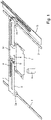
- the essential components of a microplate reader are in figure 1 shown as an example.
- the microplate reader comprises a receiving device 1 for receiving a microplate, which serves as a sample carrier.
- the recording 1 is referred to below as a plate carrier. It holds a microplate on its edge and secures it at the corners against slipping sideways. Additional, in figure 1 not shown holding means such as a spring or a spring mechanism may be provided, which additionally secures the microplate in the plate carrier 1.
- the plate carrier 1 is held on a carriage 2a of a linear guide 2 which is linearly movable in the X-direction.
- the linear guide 2 is in turn attached to two lateral linear guides 3 via two linearly movable carriages 3a in the Y-direction.
- the plate carrier 1, and with it a microplate accommodated therein, can be positioned freely in the X and Y directions via the linear guides 2, 3.
- an optical detector 9 is arranged below the plate carrier 1, an optical detector 9 is arranged below the plate carrier 1, an optical detector 9 is arranged below the plate carrier 1, an optical detector 9 is arranged below the plate carrier 1, an optical detector 9 is arranged below the plate carrier 1, an optical detector 9 is arranged below the plate carrier 1, an optical detector 9 is arranged below the plate carrier 1, an optical detector 9 is arranged below the plate carrier 1, an optical detector 9 is arranged below the plate carrier 1, an optical detector 9 is arranged below the plate carrier 1, an optical detector 9 is arranged.
- the optical detector 9 can be a photomultiplier, for example,
- a photomultiplier instead of a photomultiplier, other optical detectors such as a photocell, a CMOS or CCD sensor, a microchannel plate (MCP), a photodiode, a photoresistor, etc., and in particular a camera can also be used for image recording.
- CMOS or CCD sensor a CMOS or CCD sensor
- MCP microchannel plate
- a photodiode a photoresistor, etc.
- a camera can also be used for image recording.
- the microplate is moved via the positioning system formed by the linear guides 2, 3 in such a way that the individual wells of the microplate are located one after the other at the measurement position defined by the detection area of the optical detector 9.
- the measuring position is defined in FIG. 1 by the axis of the optical detector 9, with which the optical radiation perpendicular to the microplate is measured from below.
- the optical detector is arranged above the microplate and measures the optical radiation above the microplate.
- an interface device On the side of the plate carrier 1 facing the carriage 2a is an interface device with an electrical interface 4 for power supply and data transmission as well as a hose connection 5, which is used to supply media to an accessory device inserted into the plate carrier 1.
- the electrical interface 4 is realized by electrical contact surfaces which are arranged behind the receiving position of a microplate. The contact surfaces are arranged in such a way that they have no effect when using a normal microplate.
- the hose connection 5 is also arranged behind the receiving position of the microplate.
- the interface device 4, 5 is connected to corresponding systems of the microplate reader, ie a control device and a medium supply device, by a multi-wire cable and a hose 6.
- An accessory device of suitable dimensions can be inserted into the plate carrier 1 either in addition to a microplate or instead of a microplate and connected to the microplate reader via the interface device 4, 5.
- Such an accessory device can be used to implement accessory functions that can be used, for example, for a specific measurement or for cleaning, calibrating or qualifying the microplate reader.
- FIG 2 such an accessory device is shown as an example, which is inserted into the plate carrier 1 instead of a microplate.
- the accessory device has contact springs 10 on its rear-facing side, which produce an electrical connection to the contact surfaces of the electrical interface 4 when they are inserted into the plate carrier 1 .
- the housing 11 of the accessory device is designed to fit snugly in the plate carrier 1 and the contact springs 10 forming a mating point for the interface 4 are aligned at the appropriate position.
- the accessory device contains a printed circuit board 13 with UV light sources 12 arranged at the corners, which are controlled by control electronics housed on the printed circuit board 13 and are electrically supplied and activated via the electrical interface 4 .
- the UV light sources are used to kill any germs in the microplate compartment of the microplate reader and thus disinfect the microplate compartment.
- UV light sources 12 instead of or in addition to the UV light sources 12, however, various sensors such as a temperature sensor, a humidity sensor, a position or acceleration sensor, a gas sensor, an optical sensor for measuring an excitation light source of the microplate reader, touch or proximity sensors or a Fan or a vacuum cleaner can be arranged.
- sensors such as a temperature sensor, a humidity sensor, a position or acceleration sensor, a gas sensor, an optical sensor for measuring an excitation light source of the microplate reader, touch or proximity sensors or a Fan or a vacuum cleaner can be arranged.
- the accessory device can also be designed in such a way that it can be inserted into the plate carrier 1 together with a microplate.
- the accessory device can have additional functions such as a storage device, a heater, an illumination device for the microplate, measuring or excitation electrodes or a shaking device for the microplate.
- FIG 3 a block diagram of the microplate reader is shown again. It comprises a receiving device 1 for microplates, with an interface device 16 having an electrical interface 4 and a media interface 5 being arranged on the receiving device 1 .
- An accessory device 20 is inserted into the receiving device 1 .
- This has a counterpart 21 that matches the interface device 16 and that uses the interface device 16 to create an electrical connection and a media connection between the microplate reader and the accessory device 20 .
- the accessory device 20 can be inserted into the receiving device together with or instead of a microplate.
- the accessory device 20 has a control and measurement circuit 22, which can be implemented by a microprocessor, for example.
- the control and measurement circuit 22 is connected to one or more sensors 23, reads their measured values and transmits them via the interface device 16 to the microplate reader.
- the control and measurement circuit 22 is connected to one or more actuators 24 .
- actuators can be, for example, a heater, a lighting device, a UV light source, electrodes or an actuator such as a valve or a metering pump, a vacuum cleaning device or a fan.
- sensors can be a temperature sensor, a humidity sensor, a position or acceleration sensor, a gas sensor, an optical sensor, a touch or proximity sensor or the like.
- the accessory device 20 has a media distribution device 25 which is connected to the media connection 5 of the interface device and which forwards the medium made available at the media connection 5 to individual wells of a microplate in an application-specific manner.
- the microplate reader has a programmable control device 15 of a type known per se, such as a control computer, controller, CPU, FPGA, microcontroller or the like.
- the control device is connected to the optical detector 9 and receives and processes its measured values.
- the control device 15 is connected to drive motors 17a, 17b, with which the figure 1 shown linear guides 2, 3 are driven.
- the control device 15 can thus position a microplate inserted in the removal device 1 such that the individual wells of the microplate are successively brought into the detection area of the detector 9 and the microplate can thus be read well by well.
- control device 15 is connected to interface device 16 and uses it to receive data signals from control and measurement circuit 22 or send command signals to control and measurement circuit 22.
- control device 15 is connected to a medium supply device 18 and controls it.
- the medium supply device 18 is connected to the media distribution device 25 of the accessory device via a hose line and the media connection 5 .
- Medium supply device 18 provides one or more media for the distribution device 25 of the accessory device 20 via the media connection 5 of the interface device 16 .
- the medium supply device 18 can be implemented, for example, by a media pump and a media container connected to it.
- an accessory device is shown as an example, which is inserted into the plate carrier 1 together with a 12-well microplate.
- the accessory device is placed on the microplate like a lid. Matching each microplate well, the accessory has an opening through which the measurement can take place unhindered.
- the accessory device has a cavity between a top wall 30 and a bottom wall 31 over which the medium can spread.
- the medium is introduced into said cavity via a hose connection 32 that fits the interface device of the microplate reader and flows out through at least one nozzle 33 for each microplate well. This ensures that the introduced atmosphere reaches the sample directly and the point in time of the gas supply is specified exactly for all samples, in contrast to the gas introduction into the entire incubator.
- the gas sensor represents an expedient addition to media distribution and can be plugged into a corresponding data and power connection of the interface device in order to measure a gas concentration in the immediate vicinity of the microplate.
- figure 5 shows in a further exemplary embodiment, as an exploded drawing, the structure of an accessory device which accommodates a microplate and is inserted into the plate carrier together with the microplate.
- the accessory device is used to shake the sample to mix the liquid(s) in the sample.
- the shaking of samples caused by movement of the plate carrier is typically limited in the shaking frequency to a few hundred RPM by the inertia of the plate carrier and the moving parts.
- the accessory device shown is inserted together with the microplate in the plate carrier, which moves the microplate relative to the plate carrier with a vibration motor.
- the accessory device shown allows measurement from above, eg fluorescence or luminescence.
- the accessory device includes a frame 20 which fits into the plate carrier of the microplate reader.
- the mount 22 for the microplate is mounted on these via an oscillating suspension, in the example via springs 21 .
- the recording is preferably built very light, so it has a low mechanical inertia.
- a printed circuit board 23 carrying a controller and a vibration motor 24 is mounted on the underside of the receptacle.
- the printed circuit board is connected via a cable connection to a contacting device 25 that matches the interface device of the plate carrier and is mounted on the frame in such a way that a connection is established when it is placed in the plate carrier.
- figure 6 shows an accessory device in the form of a printed circuit board with 96 LEDs, which are placed in the plate carrier together with the microplate in order to obtain an individual irradiation of each well of a 96-well microplate.
- the supply and control of the LEDs is achieved by plug-in contacts via the interface of the plate carrier.
- all or individual wells a 96-well microplate can be illuminated in a targeted manner, for example to support biological or photochemical processes taking place therein, and can be switched off individually for a measurement on the relevant well.
Landscapes
- Health & Medical Sciences (AREA)
- Chemical & Material Sciences (AREA)
- Analytical Chemistry (AREA)
- General Health & Medical Sciences (AREA)
- Physics & Mathematics (AREA)
- General Physics & Mathematics (AREA)
- Biochemistry (AREA)
- Life Sciences & Earth Sciences (AREA)
- Immunology (AREA)
- Pathology (AREA)
- Clinical Laboratory Science (AREA)
- Chemical Kinetics & Catalysis (AREA)
- Nuclear Medicine, Radiotherapy & Molecular Imaging (AREA)
- Hematology (AREA)
- Spectroscopy & Molecular Physics (AREA)
- Investigating, Analyzing Materials By Fluorescence Or Luminescence (AREA)
- Automatic Analysis And Handling Materials Therefor (AREA)
- Investigating Or Analysing Materials By Optical Means (AREA)
Abstract
Description
- Die vorliegende Erfindung betrifft ein Mikroplatten-Lesegerät mit einer Aufnahmevorrichtung zur Aufnahme einer Mikroplatte vorgegebener Abmessungen, die eine Vielzahl von Vertiefungen aufweist, und mit einem optischen Detektor zur Erfassung einer optischen Strahlung an jeweils einzelnen der Vertiefungen einer in der Aufnahmevorrichtung aufgenommenen Mikroplatte, wobei die Aufnahmevorrichtung über eine Positioniermechanik in mindestens eine Raumrichtung beweglich angeordnet ist, um die aufgenommene Mikroplatte bezüglich des optischen Detektors für aufeinanderfolgende Messungen an unterschiedlichen Vertiefungen zu positionieren.
- Bei einer Mikroplatte handelt es sich um einen Probenträger zur Durchführung photometrischer oder anderer Messungen, der eine Vielzahl in regelmäßigen Abständen angeordneter Vertiefungen - englisch Wells - aufweist, in welche Proben pipettiert werden können. Mikroplatten haben genormte Abmessungen mit jeweils gleicher Grundfläche und zum Teil variabler Höhe und sind mit unterschiedlicher Anzahl Wells verfügbar, zum Beispiel 6×8, 8×12, 16×24, 32×48 oder 48x72 Wells. Ein Mikroplatten-Lesegerät dient zum "Auslesen" von Mikroplatten, indem an den einzelnen Wells photometrische Messungen durchgeführt werden. Hierzu besitzt ein Mikroplatten-Lesegerät einen optischen Detektor wie etwa einen Photomultiplier, der von den in den einzelnen Wells enthaltenen Proben aufgrund Absorption, Lumineszenz oder Fluoreszenz aus- oder durchgehende optische Strahlung detektiert. Die Mikroplatte wird hierzu in eine Aufnahmevorrichtung eingesetzt, die über eine Positioniermechanik in X- und Y-Richtung beweglich ist. Zum sequenziellen Auslesen der einzelnen Wells werden diese nacheinander von der Positioniermechanik in den Erfassungsbereich des optischen Detektors gebracht.
- Die photometrische Untersuchung von Probenreihen mit einem Mikroplatten-Lesegerät kommt in breiten Anwendungsfeldern zum Einsatz, unter anderem zum Erkennen von biologischen, chemischen, biochemischen oder physikalischen Reaktionen der Proben. Je nach Anwendungsfall können Zusatzfunktionen benötigt werden, um entsprechende Reaktionen auszulösen, zu unterhalten, oder in sonstiger Weise zu unterstützen. Darüber hinaus können auch Messsensoren für zusätzliche Messfunktionen benötigt werden. Werden solche Zusatzfunktionen benötigt, müssen entsprechende Gerätschaften in das Mikroplatten-Lesegerät integriert sein. Entsprechende anwendungsspezifische Anpassungen sind aufwendig und teuer und müssen zudem bereits bei der Konzeption und Auslegung des Gesamtgeräts berücksichtigt werden.
- Darüber hinaus kann es erforderlich sein zur Kalibrierung und Qualifizierung zusätzliche Sensoren in dem Gerät vorzusehen, um zu überprüfen, ob das Gerät die entsprechenden Spezifikationen einhält und um erforderlichenfalls Geräteparameter einzustellen. Derartige Überprüfungen und Einstellungen am Gerät können sowohl vor Auslieferung als auch im Laufe der Lebenszeit des entsprechenden Geräts erforderlich sein. Derartige zusätzliche Sensoren erhöhen ebenfalls die Komplexität des Geräts.
- Es ist daher eine Aufgabe der vorliegenden Erfindung, ein Mikroplatten-Lesegerät anzugeben, welches in unterschiedlichen Anwendungsgebieten flexibel einsetzbar ist und insbesondere eine Nachrüstung von Zusatzfunktionen ermöglicht.
- Die Aufgabe wird gelöst durch die Merkmale des Anspruchs 1. Vorteilhafte Ausgestaltungen sind den abhängigen Ansprüchen zu entnehmen. Darüber hinaus werden in den Ansprüchen 5 bis 9 Zubehörvorrichtungen angegeben, die mit dem erfindungsgemäßen Mikroplatten-Lesegerät verwendet werden können.
- Erfindungsgemäß ist bei einem Mikroplatten-Lesegerät der eingangs genannten Art vorgesehen, dass die beweglich angeordnete Aufnahmevorrichtung für Mikroplatten eine Schnittstelleneinrichtung aufweist, die ausgebildet ist, eine Energie- und/oder Datenverbindung - vorzugsweise Energie- und Datenverbindung - und/oder eine Verbindung zur Medien-Versorgung und/oder Medien-Entsorgung von dem Mikroplatten-Lesegerät zu einer gemeinsam mit oder anstelle einer Mikroplatte oder einem anderen Probenbehältnis in die Aufnahmevorrichtung eingesetzten Zubehörvorrichtung für Zusatzfunktionen bereitzustellen.
- Die Aufnahmevorrichtung ist über die Positioniermechanik bevorzugt in zwei Raumrichtungen (X- und Y-Richtung) gegenüber dem optischen Detektor für aufeinanderfolgende Messungen an unterschiedlichen Vertiefungen positionierbar. Denkbar ist jedoch auch, dass der optische Detektor aus mehreren Sensoren besteht, mit denen eine ganze Zeile an Vertiefungen in einem Schritt gemessen werden kann. In diesem Fall erfolgt das Auslesen der Mikroplatte zeilenweise, sodass die Aufnahmevorrichtung in nur einer Raumrichtung gegenüber dem Detektor verstellbar zu sein braucht.
- Im Rahmen der vorliegenden Erfindung ist auch ein Mikroplatten-Lesegerät mit umfasst, welches als optischen Detektor einen bildgebenden Detektor wie etwa eine CCD-Kamera mit geeigneter Vergrößerungsoptik (Objektiv) oder einem Mikroskop aufweist und ausgebildet ist, Bildserien der einzelnen Wells zu erzeugen.
- Die Schnittstelleneinrichtung kann an der Aufnahmevorrichtung direkt oder einem mechanisch mit der Aufnahmevorrichtung verbundenen Bauteil, etwa einem Schlitten der Positioniermechanik angeordnet sein.
- Die Schnittstellenvorrichtung ermöglicht es, Zusatzhardware in Form einer Zubehörvorrichtung mit Energie und Kommunikation zu versorgen. Als Aufnahme dient die ohnehin vorhandene Aufnahmevorrichtung für Mikroplatten. Zusatzfunktionen können somit in einer Zubehörvorrichtung integriert werden, die kompatibel zur Aufnahmevorrichtung für Mikroplatten und der dort vorgesehenen Schnittstellenvorrichtung ist. Die genannte Schnittstelleneinrichtung hat zunächst keinen Einfluss auf das Gesamtgerät. Das Einsetzen einer entsprechenden Zubehörvorrichtung in die Aufnahmevorrichtung für Mikroplatten ermöglicht eine tiefe Integration in das Gesamtgerät bei hohem Automatisierungsgrad. Durch Softwareupdates einer Steuerungsvorrichtung des Mikroplatten-Lesegerätes können auch Funktionen unterstützt werden, die bei der Herstellung des Mikroplatten-Lesegerätes selbst noch nicht vorgesehen waren. Eine entsprechende Schnittstellenvorrichtung in der Aufnahmevorrichtung ist universell einsetzbar und einfach und kostengünstig zu realisieren. Anwendungsspezifische Zusatzfunktionen können in separate Zubehörvorrichtungen ausgelagert werden. Mit gesondert gefertigtem Zubehör sind Zusatzfunktionen realisierbar, die nicht nur der Hersteller des Lesegerätes bereitgestellt, sondern die vom Anwender selbst oder von Dritten entwickelt werden. Zusatzfunktionen können zusätzlich, in Kombination oder sogar zeitgleich mit den Grundfunktionen des Mikroplatten-Lesegerätes verwendet werden.
- Im Rahmen der vorliegenden Erfindung kann die Schnittstelleneinrichtung insbesondere derart ausgebildet sein, dass die Energie- und/oder Datenverbindung über elektrische Kontakte, mittels optischer Signalübertragung und/oder durch Kopplung über elektrische, magnetische oder elektromagnetische Felder hergestellt wird. Die Energie- und/oder Datenverbindung kann somit über eine Steckverbindung oder auch drahtlos erfolgen. Eine Energieübertragung kann über elektrische Kontakte oder auch induktiv erfolgen. Die Schnittstelleneinrichtung kann hierbei auf herkömmlichen Schnittstellenformaten, etwas einem USB-Anschluss für elektrische Strom- und Datenverbindung, oder einer drahtlos-Schnittstelle nach den RFID, WLAN oder Bluetooth-Standards basieren.
- Im Rahmen der Erfindung kann vorgesehen sein, dass die Schnittstelleneinrichtung eine mittels einer Schlauchverbindung ausgeführte Medienschnittstelle zur Medienversorgung oder Medienentsorgung umfasst, insbesondere zur Ver-und/oder Entsorgung mit bzw. von mindestens einem der folgenden Medien: Luft, CO2, Sauerstoff, Stickstoff, Wasser (ggf. temperiert zur Kühlung oder Erwärmung der Proben), Reagenzien. Auf diese Weise können in den Wells einer Mikroplatte ablaufende Reaktionen unterstützt, unterhalten oder auf sonstige Weise zum Ablauf solcher Reaktionen beigetragen werden.
- Hierbei kann die Medienschnittstelle insbesondere durch eine Schlauchverbindung ausgeführt sein. Hierzu wird vorzugsweise an der Schnittstellenvorrichtung ein entsprechender Schlauchanschluss vorgesehen, der mit einem passenden Gegenstück auf der Seite einer mit der Schnittstelleneinrichtung zusammenwirkenden Zubehörvorrichtung verbunden wird.
- Darüber hinaus kann im Rahmen der vorliegenden Erfindung eine Steuerungseinrichtung vorgesehen sein, die ausgebildet ist, über die Schnittstelleneinrichtung Zusatzfunktionen einer gemeinsam mit oder anstelle einer Mikroplatte in die Aufnahmevorrichtung eingesetzten Zubehörvorrichtung zu aktivieren. Dies kann durch Freischalten einer Energieversorgung oder durch entsprechende Steuerbefehle an einer Datenschnittstelle geschehen. Eine derartige Steuerungseinrichtung kann insbesondere als programmierbare Steuerungseinrichtung ausgeführt sein, die mit einem entsprechenden Steuerungsprogramm betrieben wird. Ein Steuerungsprogramm lässt sich jederzeit aktualisieren, um so zusätzliche Funktionen von speziellen Zubehörvorrichtungen zu unterstützen und zu aktivieren. Darüber hinaus empfängt die Steuerungseinrichtung in Rückrichtung Daten, insbesondere Sensordaten, Messdaten, Bestätigungsnachrichten und dergleichen von einer über die Schnittstelleneinrichtung gesteuerten Zubehörvorrichtung und verarbeitet diese.
- Eine entsprechende, mit dem Mikroplatten-Lesegerät zusammenwirkende Zubehörvorrichtung umfasst eine mit der Schnittstelleneinrichtung des Mikroplatten-Lesegeräts zusammenwirkende Gegenstelle, über die eine von dem Zubehör bereitgestellte Zusatzfunktion angesteuert und/oder mit Energie versorgt wird. Eine derartige Zubehörvorrichtung kann entweder gemeinsam mit einer Mikroplatte in die Aufnahmevorrichtung des Mikroplatten-Lesegeräts eingelegt werden oder anstelle einer solchen Mikroplatte. Im erstgenannten Fall ist selbstverständlich auch umfasst, dass die Zubehörvorrichtung auf einer Mikroplatte integriert angeordnet ist. Die Verwendung einer Zubehörvorrichtung anstelle einer Mikroplatte kann vorgesehen sein, wenn die Zubehörvorrichtung Zusatzfunktionen zur Wartung, Qualifizierung, Kalibrierung oder Reinigung des Mikroplatten-Lesegeräts bereitstellt.
- Eine weitere Verwendung einer Zubehörvorrichtung anstelle einer Mikroplatte kann vorgesehen sein, wenn die Zubehörvorrichtung neben einer Zusatzfunktion auch ein oder mehrere Probenbehältnisse trägt. In diesem Fall dient die Zusatzfunktion zur Manipulation oder Messung der Proben in den Behältnissen, die zweckmäßig austauschbar sind und als Verbrauchsware standardisiert sind. Auch spezielle Behältnisse, beispielsweise mit eingelassenen Elektroden können tauschbar mit der zusätzlichen Messelektronik auf der Zubehörvorrichtung in dem Format der Mikroplatte eingerichtet werden.
- Eine Zubehörvorrichtung, die anstelle einer Mikroplatte eingelegt wird, kann zusätzlich zu einer von ihr bereitgestellten und über die Schnittstelleneinrichtung angeschlossene Zusatzfunktion auch als ein Adapter eingesetzt werden, um nach einem Baukastenprinzip ein oder mehrere einzelne oder miteinander verbundene (sogenannte Stripes) Probenbehälter aufzunehmen und an die standardisierte Plattengröße (127,76mm × 85,48mm gemäß ANSI-Standard auf Empfehlung der Society for Biomolecular Screening) anzupassen. Die Zubehörvorrichtung hat somit eine Doppelfunktion, einerseits als mechanischer Adapter für Probenbehälter abweichender Abmessungen, anderseits zur Durchführung von Zusatzfunktionen an den aufgenommenen Probenbehältern.
- Eine Verwendung einer Zubehörvorrichtung gemeinsam mit einer Mikroplatte kann insbesondere vorgesehen sein, um in den Wells einer Mikroplatte ablaufende Reaktionen auszulösen oder zu unterstützen oder zusätzliche Messmethoden zu ermöglichen. Zur gemeinsamen Nutzung kann die Zubehörvorrichtung ober- und/oder unterhalb der Mikroplatte eine Funktionseinheit tragen. Eine optische Messung kann in diesem Fall von der jeweils gegenüberliegenden Seite erfolgen. Die Zubehörvorrichtung kann auch so ausgelegt werden, dass für einen Teil der Mikroplatte die Lichtdurchgängigkeit gewährleistet ist und die Zusatzfunktionseinheit den anderen Teil ober- und oder unterhalb der Mikroplatte als Bauraum verwendet.
- Im Rahmen der Erfindung kann eine Zubehörvorrichtung bei einer eingelegten Mikroplatte auch derart in die Aufnahmevorrichtung eingefügt werden, indem sie auf die Schnittstelleneinrichtung aufgesteckt wird. Bei geeigneter Miniaturisierung der Zubehörvorrichtung kann auf eine weitere mechanische Halterung verzichtet werden. Vorzugsweise können z.B. Sensoren auf die Schnittstelleneinrichtung aufgesteckt werden, um in unmittelbarer Nähe zur Probe Messwerte wie beispielsweise die Luftfeuchtigkeit zu messen.
- Bei einer Ausführungsform einer Zubehörvorrichtung ist diese ausgebildet, gemeinsam mit einer Mikroplatte in die Aufnahmevorrichtung des Mikroplatten-Lesegeräts eingelegt werden und weist mindestens eine Temperiereinheit, insbesondere Heizung, auf, die über die Schnittstelleneinrichtung angesteuert und mit Energie versorgt wird, um in Vertiefungen der Mikroplatte enthaltene Proben zu temperieren. Auf diese Weise kann insbesondere eine Inkubationsfunktion des Mikroplatten-Lesegeräts geschaffen oder verbessert werden.
- Bei einer weiteren Ausführungsform kann die Zubehörvorrichtung ausgebildet sein, gemeinsam mit einer Mikroplatte - oberhalb oder unterhalb dieser - in die Aufnahmevorrichtung des Mikroplatten-Lesegeräts eingelegt zu werden und weist mindestens eine Beleuchtungseinrichtung auf, die über die Schnittstelleneinrichtung angesteuert und mit Energie versorgt wird. Auf diese Weise kann bei in die Vertiefungen der Mikroplatte eingefüllten Proben durch Lichteinstrahlung eine Reaktion herbeigeführt oder eine optische Eigenschaft gemessen werden. Die Beleuchtungseinrichtung kann insbesondere ausgebildet sein, eine individuelle Bestrahlung der einzelnen Wells der Mikroplatte zu erzeugen. Dies kann beispielsweise mittels individueller LEDs je Wells erreicht werden. Die Ansteuerung und Versorgung der LEDs kann über die Schnittstelle der Aufnahmevorrichtung erfolgen. So sind beispielsweise Experimente möglich, die eine kontinuierliche oder zeitgesteuerte Bestrahlung aller Proben erfordert, auch wenn die Proben nacheinander, beispielsweise in Fluoreszenz gemessen werden.
- Bei einer weiteren Ausführungsform ist die Zubehörvorrichtung ausgebildet, gemeinsam mit einer Mikroplatte in die Aufnahmevorrichtung des Mikroplatten-Lesegeräts eingelegt zu werden und weist zu einer oder mehreren der Vertiefungen der Mikroplatte führende Elektroden sowie eine mit den Elektroden verbundene Steuer- oder Messelektronik auf, die über die Schnittstelleneinrichtung angesteuert wird, um in den Vertiefungen der Mikroplatte enthaltene Proben elektrisch anzuregen oder eine elektrische Eigenschaft der Proben zu messen. Somit können gleichzeitig mit einer photometrischen Untersuchung auch elektrische Messungen oder elektrische Anregungen vorgenommen werden. Insbesondere kann durch eine elektrische Anregung der Proben eine Reaktion herbeigeführt werden, die dann wiederum photometrischen beobachtet wird.
- In einer weiteren Ausführungsform ist die Zubehörvorrichtung ausgebildet, in die Aufnahmevorrichtung des Mikroplatten-Lesegeräts eingelegt zu werden und weist mindestens einen Temperatursensor auf, dessen Temperaturmesswerte über die Schnittstelleneinrichtung übertragen werden. Eine solche Temperaturmessfunktion kann insbesondere zur Überprüfung oder Kalibrierung einer Inkubationsfunktion des Mikroplatten-Lesegeräts verwendet werden. Die Zubehörvorrichtung kann weitergehend ausgebildet sein, Probenbehältnisse zu tragen, um mindestens einen Fühler des mindestens einen Temperatursensors in das Behältnis einzubringen, um unmittelbar die Probentemperatur zu messen.
- Bei einer weiteren Ausführungsform ist die Zubehörvorrichtung ausgebildet, in die Aufnahmevorrichtung des Mikroplatten-Lesegeräts eingelegt zu werden und weist mindestens einen Feuchtesensor auf, dessen Luftfeuchte-Messwerte über die Schnittstelleneinrichtung übertragen werden. Ein solcher Feuchtesensor kann ebenfalls zur Überprüfung oder Kalibrierung einer Inkubationsfunktion des Mikroplatten-Lesegeräts verwendet werden.
- Bei einer weiteren Ausführungsform ist die Zubehörvorrichtung ausgebildet, in die Aufnahmevorrichtung des Mikroplatten-Lesegeräts eingelegt zu werden und weist mindestens einen Sensor zum Erfassen der Lage oder Beschleunigung auf, dessen Positions- oder Beschleunigungswerte über die Schnittstelleneinrichtung übertragen werden. Ein solcher Lage- oder Beschleunigungssensor ist insbesondere hilfreich zur Überprüfung oder Kalibrierung der Positioniermechanik des Mikroplatten-Lesegeräts, um beispielsweise sicherzustellen, dass die einzelnen Vertiefungen einer Mikroplatte vorgegebener Bauart korrekt in den Erfassungsbereich des optischen Detektors positioniert werden.
- Bei einer weiteren Ausführungsform ist der Zubehörvorrichtung ausgebildet, in die Aufnahmefunktion des Mikroplatten-Lesegerätes eingelegt zu werden und weist mindestens einen Gassensor zum Erfassen einer künstlich hergestellten Atmosphäre auf, dessen Messwerte für gemessene Gaskonzentrationen über die Schnittstelleneinrichtung übertragen werden. Ein solcher Gassensor ist insbesondere zur Überprüfung oder Kalibrierung einer Atmosphärenregelungsfunktion des Mikroplatten-Lesegeräts hilfreich.
- Bei einer weiteren Ausführungsform ist die Zubehörvorrichtung ausgebildet, in die Aufnahmevorrichtung des Mikroplatten-Lesegeräts eingelegt zu werden und weist mindestens einen optischen Sensor zum Vermessen einer Anregungslichtquelle des Mikroplatten-Lesegeräts auf, dessen Messwerte über die Schnittstelleneinrichtung übertragen werden. Ein solcher optischer Sensor ist insbesondere hilfreich zur Überprüfung oder Kalibrierung einer Anregungslichtquelle des Mikroplatten-Lesegeräts.
- Bei einer weiteren Ausführungsform ist die Zubehörvorrichtung ausgebildet, in die Aufnahmevorrichtung des Mikroplatten-Lesegeräts eingelegt zu werden und weist mindestens eine Lichtquelle auf, die ausgebildet ist, ein optisches Signal mit steuerbarer Intensität, Wellenlänge und/oder Signalverlauf zu erzeugen, die über die Schnittstelleneinrichtung mit Energie versorgt und angesteuert wird. Eine solche Lichtquelle ist insbesondere hilfreich zur Überprüfung oder Kalibrierung des optischen Detektors des Mikroplatten-Lesegeräts oder weiterer im Mikroplatten-Lesegerät verbauter Messsysteme. Ebenso kann eine solche Lichtquelle zur Bestrahlung von Proben mit oder ohne Anregung der betreffenden Probe eingesetzt werden. Dazu können auf der Zubehörvorrichtung Steckplätze oder Positionsplätze für Probenbehälter vorgesehen werden.
- Bei einer weiteren Ausführungsform ist die Zubehörvorrichtung ausgebildet, in die Aufnahmevorrichtung des Mikroplatten-Lesegeräts eingelegt zu werden und weist mindestens einen Berührungs- oder Annäherungssensor auf, dessen Messwerte über die Schnittstelleneinrichtung übertragen werden. Ein solcher Berührungs- oder Annäherungssensor ist insbesondere hilfreich zur Überprüfung oder Kalibrierung von Positioniergenauigkeiten beweglicher Teilsysteme des Mikroplatten-Lesegeräts.
- Bei einer weiteren Ausführungsform ist die Zubehörvorrichtung ausgebildet, in die Aufnahmevorrichtung des Mikroplatten-Lesegeräts eingelegt zu werden und weist mindestens eine UV-Lichtquelle zum Desinfizieren des Innenraums des Mikroplatten-Lesegeräts auf, die über die Schnittstelleneinrichtung angesteuert und mit Energie versorgt wird. Auf diese Weise kann durch Einsetzen der entsprechenden Zubehörvorrichtung auf einfache und schnelle Weise der Innenraum des Mikroplatten-Lesegeräts desinfiziert werden.
- Bei einer weiteren Ausführungsform ist die Zubehörvorrichtung ausgebildet, in die Aufnahmevorrichtung des Mikroplatten-Lesegeräts eingelegt zu werden und weist mindestens eine Staubsaugvorrichtung zum Reinigen des Innenraums oder eine Blasvorrichtung zur Linsenreinigung des Mikroplatten-Lesegeräts auf, die über die Schnittstelleneinrichtung angesteuert und mit Energie versorgt wird. Somit kann durch Einsetzen der entsprechenden Zubehörvorrichtung auf einfache Weise eine Reinigung des Innenraums und von optischen Linsen durchgeführt werden.
- Bei einer weiteren Ausführungsform ist die Zubehörvorrichtung ausgebildet, in die Aufnahmevorrichtung des Mikroplatten-Lesegeräts eingelegt zu werden und weist mindestens einen Lüfter auf, der zum schnellen Abkühlen oder zum schnellen Luftwechsel im Innenraum des Mikroplatten-Lesegeräts über die Schnittstelleneinrichtung angesteuert und mit Energie versorgt wird.
- Bei einer weiteren Ausführungsform ist die Zubehörvorrichtung ausgebildet, in die Aufnahmevorrichtung des Mikroplatten-Lesegeräts eingelegt zu werden und weist ihrerseits eine bewegliche Aufnahme für eine Mikroplatte oder einen anderen Probenhalter auf sowie einen mit der beweglichen Aufnahme gekoppelten Antrieb zum Schütteln oder Durchmischen von Proben, insbesondere mittels Ultraschall, wobei der Antrieb über die Schnittstelleneinrichtung angesteuert und mit Energie versorgt wird. Durch die Zubehörvorrichtung können somit in der Mikroplatte enthaltene Proben vor, während oder zwischen Messungen durchmischt und aufgeschüttelt werden.
- Bei einer weiteren Ausführungsform ist die Zubehörvorrichtung ausgebildet, gemeinsam mit einer Mikroplatte in die Aufnahmevorrichtung eingelegt zu werden und weist einen Aktuator zum Applizieren von Reagenzien, der über die Schnittstelleneinrichtung angesteuert wird, sowie ein Verteilsystem zur Verteilung der Reagenzien in die Vertiefungen der Mikroplatte auf. Insbesondere kann der Aktuator als Ventil oder Dosierpumpe und das Verteilsystem als Mikrokanalsystem ausgeführt sein. Auf diese Weise können in den Vertiefungen ablaufende Reaktionen unterhalten, ausgelöst oder in sonstiger Weise unterstützt werden.
- Bei einer weiteren Ausführungsform ist die Zubehörvorrichtung ausgebildet, gemeinsam mit einer Mikroplatte in die Aufnahmevorrichtung eingelegt zu werden und weist mindestens eine Vorrichtung zum Zuführen und gegebenenfalls Verteilen mindestens eines Mediums an mindestens eine der Vertiefungen der Mikroplatte auf, wobei das Medium über die Schnittstelleneinrichtung bereitgestellt wird. Bei dem besagten Medium kann es sich beispielsweise um eine modifizierte Atmosphäre oder Luftfeuchtigkeit handeln, welchem in den Vertiefungen enthaltene Proben ausgesetzt werden sollen.
- Bei einer weiteren Ausführungsform ist die Zubehörvorrichtung ausgebildet, gemeinsam mit einer Mikroplatte in die Aufnahmevorrichtung eingelegt zu werden und weist mindestens eine Vorrichtung zum Zerstäuben von Flüssigkeiten zur Nebelbildung auf, wobei vorzugsweise Wasser mit einem Ultraschallgeber vernebelt wird, um eine geeignete Luftfeuchtigkeit über den Proben der Mikroplatte zu erzeugen. Die feuchte Atmosphäre kann mit einem Deckel am Verflüchtigen gehindert bzw. bei gelochten Deckel gebremst werden. Ein Vernebelungszubehör, das anstelle der Mikroplatte eingelegt wird, trägt z.B. ein Reservoir für das zu verdunstende Medium mit innenliegendem Ultraschallgeber sowie Steck- oder Stellplätze für Probenbehälter.
- Die Zubehörvorrichtung kann auch ausgebildet sein, Informationen zu der Mikroplatte bereitzustellen. Die Zubehörvorrichtung umfasst dementsprechend eine statische oder wiederbeschreibbare Speichervorrichtung, in der Informationen zu der Mikroplatte abgelegt sind oder abgelegt werden können. Die Speichervorrichtung kann insbesondere in Form eines RFID- oder anderweitigen Nahfeldchips ausgebildet sein. Hierbei ist es insbesondere vorteilhaft, wenn die Zubehörvorrichtung unlösbar mit einer zugehörigen Mikroplatte verbunden ist. In der Speichervorrichtung können z.B. Informationen zur Identifikation sowie Messdaten u.a. zu den verschiedenen Proben in den einzelnen Wells der Mikroplatte abgespeichert werden.
- Im Rahmen der vorliegenden Erfindung ist außerdem ein Mikroplatten-Lesegerät umfasst, welches mit einer in die Aufnahmevorrichtung eingesetzten Zubehörvorrichtung der zuvor genannten Art ausgestattet ist.
- Weitere Vorteile und Eigenschaften der vorliegenden Erfindung ergeben sich aus der nachfolgenden Beschreibung von Ausführungsbeispielen anhand der Figuren. Es zeigt:
- Figur 1
- eine Positioniermechanik eines Mikroplatten-Lesegeräts mit einer daran beweglich angeordneten Aufnahmevorrichtung für Mikroplatten, welche mit einer Schnittstelleneinrichtung versehen ist,
- Figur 2
- eine Zubehörvorrichtung, welche in die Aufnahmevorrichtung aus Figur 1 eingesetzt werden kann,
- Figur 3
- ein Blockdiagramm eines Mikroplatten-Lesegerätes,
- Figur 4
- eine Zubehörvorrichtung zur Medienverteilung auf einer gemeinsam mit der Zubehörvorrichtung eingesetzten Mikroplatte,
- Figur 5
- in einer Explosionsdarstellung eine Zubehörvorrichtung zum Schütteln einer gemeinsam mit der Zubehörvorrichtung eingesetzten Mikroplatte und
- Figur 6
- eine Zubehörvorrichtung mit einer Beleuchtungseinrichtung aus 96 LEDs für eine gemeinsam mit der Zubehörvorrichtung eingesetzten Mikroplatte.
- Die wesentlichen Komponenten eines Mikroplatten-Lesegerätes sind in
Figur 1 beispielhaft dargestellt. Das Mikroplatten-Lesegerät umfasst eine Aufnahmevorrichtung 1 zur Aufnahme einer Mikroplatte, die als Probenträger dient. Die Aufnahme 1 wird im Folgenden als Plattenträger bezeichnet. Sie nimmt einen Mikroplatte an ihrem Rand auf und sichert diese an den Ecken gegen seitliches Verrutschen. Hierbei können auch zusätzliche, inFigur 1 nicht gezeigte Haltemittel wie etwa eine Feder oder ein Federmechanismus vorgesehen sein, der die Mikroplatte in dem Plattenträger 1 zusätzlich sichert. - Der Plattenträger 1 ist an einem in X-Richtung linear beweglichen Schlitten 2a einer Linearführung 2 gehalten. Die Linearführung 2 ist wiederum über zwei in Y-Richtung linear bewegliche Schlitten 3a an zwei seitlichen Linearführungen 3 befestigt. Über die Linearführungen 2, 3 ist der Plattenträger 1 und mit ihm eine darin aufgenommene Mikroplatte in X und Y-Richtung frei positionierbar. Unterhalb des Plattenträgers 1 ist ein optischer Detektor 9 angeordnet. Bei dem optischen Detektor 9 kann es sich beispielsweise um einen Photomultiplier handeln, mit dem die Intensität einer von einer Probe emittierten oder transmittierten Lichtstrahlung gemessen werden kann. Zusätzlich kann eine hier nicht dargestellte Anregungslichtquelle vorgesehen sein, um die zu messenden Proben optisch anzuregen oder eine Absorption beim Durchtritt durch die Probe zu messen. Anstelle eines Photomultipliers können auch andere optische Detektoren wie etwa eine Photozelle, ein CMOS oder CCD-Sensor, eine Mikrokanalplatte (MCP), eine Photodiode, ein Photowiderstand usw. und insbesondere auch eine Kamera zur Bildaufnahme eingesetzt werden.
- Zur Durchführung einer Messung wird über das von den Linearführungen 2, 3 gebildete Positioniersystem die Mikroplatte so bewegt, dass sich die einzelnen Wells der Mikroplatte nacheinander an der von dem Erfassungsbereich des optischen Detektors 9 definierten Messposition befinden. Die Messposition ist in Figur 1 definiert durch die Achse des optischen Detektors 9, mit dem von unten die optische Strahlung senkrecht zur Mikroplatte gemessen wird. Selbstverständlich ist auch eine umgekehrte Anordnung möglich, bei der der optische Detektor oberhalb der Mikroplatte angeordnet wird und die optische Strahlung oberhalb der Mikroplatte misst.
- An der zum Schlitten 2a weisenden Seite des Plattenträgers 1 befindet sich eine Schnittstelleneinrichtung mit einer elektrischen Schnittstelle 4 für Stromversorgung und Datenübertragung sowie ein Schlauchanschluss 5, welcher zur Medienversorgung einer in den Plattenträger 1 eingesetzten Zubehörvorrichtung dient. Die elektrische Schnittstelle 4 wird durch elektrische Kontaktflächen realisiert, die hinter der Aufnahmeposition einer Mikroplatte angeordnet sind. Die Kontaktflächen sind hierbei so angeordnet, dass sie bei Verwendung einer normalen Mikroplatte keine Auswirkungen haben. Der Schlauchanschluss 5 ist ebenfalls hinter der Aufnahmeposition der Mikroplatte angeordnet. Die Schnittstelleneinrichtung 4, 5 wird durch ein mehradriges Kabel sowie einen Schlauch 6 mit entsprechenden Systemen des Mikroplattenlesers, also einer Steuerungseinrichtung und einer Mediumversorgungseinrichtung, verbunden. Hinter der Linearführung 2 und seitlich von der rechten Linearführung 3 befinden sich Führungsbleche 7, 8, in denen die Zuleitungen 6, also Kabel und Schlauch für die Schnittstelleneinrichtung 4, 5, jeweils in Schlaufen verlegt sind, sodass die Zuleitungen 6 in geeigneter Weise der Bewegung des Plattenträgers in X- und Y-Richtung folgen können.
- In den Plattenträger 1 kann entweder zusätzlich zu einer Mikroplatte oder anstelle einer Mikroplatte eine Zubehörvorrichtung mit geeigneten Abmessungen eingesetzt werden und über die Schnittstelleneinrichtung 4, 5 mit dem Mikroplatten-Lesegerät verbunden werden. Über eine solche Zubehörvorrichtung können Zubehörfunktionen realisiert werden, die beispielsweise für eine bestimmte Messung oder zur Reinigung, Kalibrierung oder Qualifizierung des Mikroplatten-Lesegeräts eingesetzt werden können.
- In
Figur 2 ist beispielhaft eine solche Zubehörvorrichtung gezeigt, welche anstelle einer Mikroplatte in den Plattenträger 1 eingelegt wird. Die Zubehörvorrichtung weist an ihrer nach hinten zeigenden Seite Kontaktfedern 10 auf, welche beim Einlegen in den Plattenträger 1 eine elektrische Verbindung zu den Kontaktflächen der elektrischen Schnittstelle 4 herstellen. Das Gehäuse 11 der Zubehörvorrichtung ist so ausgeführt, dass es genau in den Plattenträger 1 passt und die Kontaktfedern 10, die eine Gegenstelle für die Schnittstelle 4 bilden, sind an entsprechender Position ausgerichtet. - Im gezeigten Ausführungsbeispiel enthält die Zubehörvorrichtung eine Leiterplatte 13 mit an den Ecken angeordneten UV-Lichtquellen 12, die von einer auf der Leiterplatte 13 untergebrachten Steuerelektronik angesteuert und über die elektrische Schnittstelle 4 elektrisch versorgt und aktiviert werden. Die UV-Lichtquellen dienen im Ausführungsbeispiel dazu, etwaige Keime im Mikroplattenraum des Mikroplatten-Lesegeräts abzutöten und den Mikroplattenraum so desinfizieren.
- Anstelle oder zusätzlich zu den UV-Lichtquellen 12 können jedoch auch verschiedene Sensoren wie etwa ein Temperatursensor, ein Feuchtesensor, ein Lage- oder Beschleunigungssensor, ein Gassensor, ein optischer Sensor zum Vermessen einer Anregungslichtquelle des Mikroplatten-Lesegeräts, Berührungs- oder Näherungssensoren oder auch ein Lüfter oder eine Staubsaugvorrichtung angeordnet werden.
- Die Zubehörvorrichtung kann auch so ausgebildet sein, dass sie zusammen mit einer Mikroplatte in den Plattenträger 1 eingesetzt werden kann. Die Zubehörvorrichtung kann hierbei Zusatzfunktionen wie etwa eine Speichervorrichtung, eine Heizung, eine Beleuchtungseinrichtung für die Mikroplatte, Mess- oder Anregungselektroden oder auch eine Rüttelvorrichtung für die Mikroplatte aufweisen.
- Im Ergebnis wird durch die Schnittstelleneinrichtung 4, 5 eine universelle Schnittstelle geschaffen, über die mithilfe entsprechender Zubehörvorrichtungen beliebige Zusatzfunktionen nachgerüstet werden können. Somit ergibt sich neben vielfältigen Nutzungsmöglichkeiten eine Erweiterbarkeit für eine spätere Nachrüstung von Zusatzfunktionen.
- In
Figur 3 ist nochmals ein Blockschaltbild des Mikroplatten-Lesegerätes dargestellt. Es umfasst eine Aufnahmevorrichtung 1 für Mikroplatten, wobei an der Aufnahmevorrichtung 1 eine Schnittstelleneinrichtung 16 mit einer elektrischen Schnittstelle 4 und einer Medien-Schnittstelle 5 angeordnet ist. In die Aufnahmevorrichtung 1 ist eine Zubehörvorrichtung 20 eingesetzt. Diese besitzt eine zu der Schnittstelleneinrichtung 16 passende Gegenstelle 21, die mit der Schnittstelleneinrichtung 16 eine elektrische Verbindung und eine Medienverbindung zwischen Mikroplatten-Lesegerät und Zubehörvorrichtung 20 bewirkt. Die Zubehörvorrichtung 20 kann hierbei zusammen mit einer oder anstelle einer Mikroplatte in die Aufnahmevorrichtung eingesetzt sein. - Die Zubehörvorrichtung 20 besitzt eine Steuer- und Messschaltung 22, die beispielsweise durch einen Mikroprozessor realisiert sein kann. Die Steuer- und Messschaltung 22 ist mit einem oder mehreren Sensoren 23 verbunden, liest deren Messwerte aus und übermittelt diese über die Schnittstelleneinrichtung 16 zu dem Mikroplatten-Lesegerät. Außerdem ist die Steuer- und Messschaltung 22 mit einem oder mehreren Aktoren 24 verbunden.
- Aktuatoren können je nach Anwendungsfall beispielsweise eine Heizung, eine Beleuchtungseinrichtung, eine UV-Lichtquelle, Elektroden oder einen Aktuator wie etwa ein Ventil oder eine Dosierpumpe, eine Staubsaugvorrichtung oder ein Lüfter sein. Sensoren können je nach Anwendungsfall ein Temperatursensor, ein Feuchtesensor, ein Lage- oder Beschleunigungsensor, ein Gassensor, ein optischer Sensor, ein Berührungs- oder Annäherungssensor oder dergleichen sein.
- Außerdem weist die Zubehörvorrichtung 20 eine mit dem Medienanschluss 5 der Schnittstelleneinrichtung verbundenen Medienverteilvorrichtung 25 auf, die an dem Medienanschluss 5 bereitgestelltes Medium in anwendungsspezifischer Weise zu einzelnen Wells einer Mikroplatte weiterleitet.
- Das Mikroplatten-Lesegerätes besitzt eine programmierbare Steuerungseinrichtung 15 an sich bekannter Bauart, etwa einen Steuerrechner, Controller, CPU, FPGA, Mikrocontroller oder dergleichen. Die Steuerungseinrichtung ist mit dem optischen Detektor 9 verbunden und empfängt und verarbeitet dessen Messwerte. Außerdem ist die Steuerungseinrichtung 15 mit Antriebsmotoren 17a, 17b verbunden, mit denen die in
Figur 1 gezeigten Linearführungen 2, 3 angetrieben werden. Somit kann die Steuerungseinrichtung 15 eine in dem Ausnahmevorrichtung 1 eingelegte Mikroplatte so positionieren, dass nacheinander die einzelnen Wells der Mikroplatte in den Erfassungsbereich des Detektors 9 gebracht werden, und die Mikroplatte so Well für Well ausgelesen werden kann. - Außerdem ist die Steuerungseinrichtung 15 mit der Schnittstelleneinrichtung 16 verbunden und empfängt hierüber Datensignale von der Steuer- und Messschaltung 22 bzw. sendet Befehlssignale an die Steuer- und Messschaltung 22. Schließlich ist die Steuerungseinrichtung 15 mit einer Mediumversorgungseinrichtung 18 verbunden und steuert diese. Die Mediumversorgungseinrichtung 18 ist über eine Schlauchleitung und den Medienanschluss 5 mit der Medienverteilvorrichtung 25 der Zubehörvorrichtung verbunden. Mediumversorgungseinrichtung 18 stellt über den Medienanschluss 5 der Schnittstelleneinrichtung 16 ein oder mehrere Medien für die Verteilvorrichtung 25 der Zubehörvorrichtung 20 bereit. Die Mediumversorgungseinrichtung 18 kann beispielsweise durch eine Medienpumpe und einem mit dieser verbundenen Medienbehälter realisiert sein.
- In
Figur 4 ist beispielhaft eine Zubehörvorrichtung gezeigt, welche gemeinsam mit einer 12 Well Mikroplatte in den Plattenträger 1 eingelegt wird. Hierzu wird die Zubehörvorrichtung wie ein Deckel auf die Mikroplatte aufgesetzt. Passend zu jedem Mikroplatten-Well hat das Zubehör eine Öffnung, durch welche die Messung ungehindert stattfinden kann. Die Zubehörvorrichtung besitzt einen Hohlraum zwischen einer oberen Wandung 30 und einer unteren Wandung 31, über den sich das Medium verteilen kann. Über einen zur Schnittstelleneinrichtung des Mikroplatten-Lesegeräts passenden Schlauchanschluss 32 wird das Medium in besagten Hohlraum eingeleitet und strömt durch jeweils mindestens eine Düse 33 pro Mikroplatten-Well aus. Dadurch wird erreicht, dass die eingeleitete Atmosphäre direkt zur Probe gelangt und der Zeitpunkt der Gaszufuhr exakt für alle Proben spezifiziert ist im Unterschied zu der Gaseinleitung in den gesamten Inkubator. So wird der Gasverbrauch verringert und die Atmosphärenänderung gelingt schlagartig. Ein inFigur 4 nicht gezeigter Gassensor stellt eine zweckmäßige Ergänzung zur Medienverteilung dar und kann an einen entsprechenden Daten- und Stromanschluss der Schnittstelleneinrichtung aufgesteckt werden, um in der unmittelbaren Nähe der Mikroplatte eine Gaskonzentration zu messen. -
Figur 5 zeigt in einem weiteren Ausführungsbeispiel als Explosionszeichnung den Aufbau einer Zubehörvorrichtung, welche eine Mikroplatte aufnimmt und gemeinsam mit der Mikroplatte in den Plattenträger eingelegt wird. Die Zubehörvorrichtung dient dem Schütteln der Probe zur Durchmischung der Flüssigkeit(en) der Probe. Das durch Bewegung des Plattenträgers erzeugte Schütteln von Proben wird typischerweise in der Schüttelfrequenz durch die Trägheit des Plattenträgers und der bewegten Teile auf einige hundert RPM begrenzt. Zur Erreichung höherer Schüttelfrequenzen bis mehrere tausend RPM wird die gezeigte Zubehörvorrichtung gemeinsam mit der Mikroplatte in den Plattenträger eingelegt, welches mit einem Vibrationsmotor die Mikroplatte gegenüber dem Plattenträger bewegt. Die gezeigte Zubehörvorrichtung ermöglicht die Messung von oben, z.B. Fluoreszenz oder Lumineszenz. - Wie in
Figur 5 gezeigt, umfasst die Zubehörvorrichtung einen Rahmen 20, welcher in den Plattenträger des Mikroplatten-Lesegerätes passt. An diesen ist über eine schwingfähige Aufhängung, im Beispiel über Federn 21, die Aufnahme 22 für die Mikroplatte montiert. Die Aufnahme ist vorzugsweise sehr leicht gebaut, weist also eine geringe mechanische Trägheit auf. An der Unterseite der Aufnahme ist eine Leiterkarte 23 montiert, die eine Steuerung und einem Vibrationsmotor 24 trägt. Die Leiterkarte ist über eine Kabelverbindung mit einer zur Schnittstelleneinrichtung des Plattenträgers passenden Kontaktiereinrichtung 25 verbunden, welche so an den Rahmen montiert wird, dass beim Einlegen in den Plattenträger eine Verbindung hergestellt wird. -
Figur 6 zeigt eine Zubehörvorrichtung in Form einer Leiterplatte mit 96 LEDs, die gemeinsam mit der Mikroplatte in den Plattenträger gelegt werden, um eine individuelle Bestrahlung eines jeden Wells einer 96 Well Mikroplatte zu erhalten. Die Versorgung und Steuerung der LEDs wird durch Steckkontakte über die Schnittstelle des Plattenträgers erreicht. Somit können alle oder einzelne Wells einer 96 Well Mikroplatte zielgerichtet beleuchtet werden, beispielsweise um darin ablaufende biologische oder photochemische Prozesse zu unterstützen, und einzeln für eine Messung am betreffenden Well kurzzeitig abgeschaltet werden.
Claims (10)
- Mikroplatten-Lesegerät mit einer Aufnahmevorrichtung (1) zur Aufnahme einer Mikroplatte vorgegebener Abmessungen, die eine Vielzahl von Vertiefungen aufweist, und mit einem optischen Detektor (9) zur Erfassung einer optischen Strahlung an jeweils einzelnen der Vertiefungen einer in der Aufnahmevorrichtung aufgenommenen Mikroplatte, wobei die Aufnahmevorrichtung über eine Positioniermechanik (2, 3) in zumindest einer Raumrichtung beweglich angeordnet ist, um die aufgenommene Mikroplatte bezüglich des optischen Detektors (9) für aufeinanderfolgende Messungen an unterschiedlichen Vertiefungen zu positionieren,
dadurch gekennzeichnet, dass
die Aufnahmevorrichtung (1) eine Schnittstelleneinrichtung (16) aufweist, die ausgebildet ist, eine Energie- und/oder Datenverbindung und/oder eine Verbindung zur Medien-Versorgung und/oder Medien-Entsorgung von dem Mikroplatten-Lesegerät zu einer gemeinsam mit oder anstelle einer Mikroplatte oder einem anderen Probenbehälter in die Aufnahmevorrichtung (1) eingesetzten Zubehörvorrichtung für Zusatzfunktionen bereitzustellen. - Mikroplatten-Lesegerät nach Anspruch 1, bei dem die Schnittstelleneinrichtung (16) ausgebildet ist, die Energie- und/oder Datenverbindung über elektrische Kontakte (4), mittels optischer Signalübertragung und/oder durch Kopplung über elektrische, magnetische oder elektromagnetische Felder herzustellen.
- Mikroplatten-Lesegerät nach Anspruch 1, bei dem die Schnittstelleneinrichtung (16) eine mittels einer Schlauchverbindung (5) ausgeführte Medien-Schnittstelle (5) zur Medien-Versorgung und/oder Medien-Entsorgung bereitstellt, insbesondere zur Ver- und/oder Entsorgung mit bzw. von mindestens einem der folgenden Medien: Luft, CO2, Sauerstoff, Stickstoff, Wasser, Reagenzien.
- Mikroplatten-Lesegerät nach einem der vorangehenden Ansprüche, mit einer Steuerungseinrichtung (15), die ausgebildet ist, über die Schnittstelleneinrichtung (16) Zusatzfunktionen einer gemeinsam mit oder anstelle einer Mikroplatte in die Aufnahmevorrichtung (1) eingesetzten Zubehörvorrichtung (20) zu aktivieren.
- Zubehörvorrichtung zur Verwendung mit einem Mikroplatten-Lesegerät nach einem der Ansprüche 1 bis 4, mit einer mit der Schnittstelleneinrichtung (16) des Mikroplatten-Lesegeräts zusammenwirkenden Gegenstelle (21, 10), über die eine von der Zubehörvorrichtung (20) bereitgestellte Zusatzfunktion angesteuert und/oder mit Energie versorgt wird.
- Zubehörvorrichtung nach Anspruch 5, wobei die Zubehörvorrichtung (20) ausgebildet ist, gemeinsam mit einer Mikroplatte in die Aufnahmevorrichtung des Mikroplatten-Lesegeräts eingelegt zu werden und mindestens eine der folgenden Einrichtungen aufweist:- eine Temperiereinheit, insbesondere Heizung, die über die Schnittstelleneinrichtung (16) angesteuert und mit Energie versorgt wird, um in Vertiefungen der Mikroplatte enthaltene Proben zu temperieren;- eine Beleuchtungseinrichtung, die über die Schnittstelleneinrichtung (16) angesteuert und mit Energie versorgt wird;- zu einer oder mehrerer der Vertiefungen der Mikroplatte führende Elektroden sowie eine mit den Elektroden verbundene Steuer- oder Messelektronik, die über die Schnittstelleneinrichtung (16) angesteuert wird, um in den Vertiefungen der Mikroplatte enthaltene Proben elektrisch anzuregen oder eine elektrische Eigenschaft der Proben zu messen;- eine Vorrichtung zum Zuführen und gegebenenfalls Verteilung mindestens eines Mediums an mindestens eine der Vertiefungen der Mikroplatte, wobei das Medium über die Schnittstelleneinrichtung (16) bereitgestellt wird; oder- einen Aktuator, insbesondere ein Ventil oder eine Dosierpumpe, zum Applizieren von Reagenzien, der über die Schnittstelleneinrichtung (16) angesteuert wird, sowie ein Verteilsystem, insbesondere Mikrokanalsystem, zur Verteilung der Reagenzien in die Vertiefungen der Mikroplatte.
- Zubehörvorrichtung nach einem der Ansprüche 6 oder 7, wobei die Zubehörvorrichtung (20) eine bewegliche Aufnahme für eine Mikroplatte oder einen anderen Probenbehälter, sowie einem mit der beweglichen Aufnahme gekoppelten Antrieb zum Schütteln und Durchmischen von Proben, insbesondere Ultraschallschüttler, aufweist und der Antrieb über die Schnittstelleneinrichtung (16) angesteuert und mit Energie versorgt wird.
- Zubehörvorrichtung nach Anspruch 6, wobei die Zubehörvorrichtung ausgebildet ist, in die Aufnahmevorrichtung des Mikroplatten-Lesegeräts eingelegt zu werden und eine der folgenden Einrichtungen aufweist:- einen Temperatursensor, dessen Temperaturmesswerte über die Schnittstelleneinrichtung (16) übertragen werden;- einen Feuchtesensor, dessen Luftfeuchtemesswerte über die Schnittstelleneinrichtung (16) übertragen werden;- einen Sensor zum Erfassen der Lage oder Beschleunigung aufweist, dessen Positions- oder Beschleunigungswerte über die Schnittstelleneinrichtung (16) übertragen werden;- einen Gassensor zum Erfassen einer künstlich hergestellten Atmosphäre aufweist, dessen Messwerte für gemessene Gaskonzentrationen über die Schnittstelleneinrichtung (16) übertragen werden;- einen optischen Sensor zum Vermessen einer Anregungslichtquelle des Mikroplatten-Lesegeräts aufweist, dessen Messwerte über die Schnittstelleneinrichtung (16) übertragen werden;- eine Lichtquelle aufweist, die ausgebildet ist, ein optisches Signal mit steuerbarer Intensität, Wellenlänge und/oder Signalverlauf zu erzeugen, die über die Schnittstelleneinrichtung (16) mit Energie versorgt und angesteuert wird;- einen Berührungs- oder Annäherungssensor aufweist, dessen Messwerte über die Schnittstelleneinrichtung (16) übertragen werden- eine UV-Lichtquelle (12) zum Desinfizieren eines Innenraums des Mikroplatten-Lesegeräts aufweist, die über die Schnittstelleneinrichtung (16) angesteuert und mit Energie versorgt wird;- mindestens eine Staubsaugvorrichtung zum Reinigen eines Innenraums des Mikroplatten-Lesegeräts aufweist, die über die Schnittstelleneinrichtung (16) angesteuert und mit Energie versorgt wird;- eine Blasvorrichtung zum Reinigen von Optiken im Mikroplatten-Lesegerät, die über die Schnittstelleneinrichtung (16) angesteuert und mit Energie versorgt wird;- einen Lüfter, der zum schnellen Abkühlen oder zum schnellen Luftwechsel in einem Innenraum des Mikroplatten-Lesegeräts über die Schnittstelleneinrichtung (16) angesteuert und mit Energie versorgt wird.
- Zubehörvorrichtung nach Anspruch 5 oder 6, wobei die Zubehörvorrichtung (20) ausgebildet ist, in die Aufnahmevorrichtung des Mikroplatten-Lesegeräts eingelegt zu werden und mindestens einen Steck- oder Stellplätze für einen Probenbehälter aufweist.
- Mikroplatten-Lesegerät nach einem der Ansprüche 1 bis 4 mit einer in die Aufnahmeeinrichtung (1) eingesetzten Zubehörvorrichtung (20) nach einem der Ansprüche 5 bis 9.
Applications Claiming Priority (1)
| Application Number | Priority Date | Filing Date | Title |
|---|---|---|---|
| DE102020128003.3A DE102020128003A1 (de) | 2020-10-23 | 2020-10-23 | Mikroplatten-Lesegerät |
Publications (3)
| Publication Number | Publication Date |
|---|---|
| EP3988924A2 true EP3988924A2 (de) | 2022-04-27 |
| EP3988924A3 EP3988924A3 (de) | 2022-07-20 |
| EP3988924B1 EP3988924B1 (de) | 2023-11-29 |
Family
ID=73747495
Family Applications (1)
| Application Number | Title | Priority Date | Filing Date |
|---|---|---|---|
| EP21199753.1A Active EP3988924B1 (de) | 2020-10-23 | 2021-09-29 | Kombination eines mikroplatten-lesegeräts mit einer zubehörvorrichtung |
Country Status (3)
| Country | Link |
|---|---|
| US (1) | US12152987B2 (de) |
| EP (1) | EP3988924B1 (de) |
| DE (1) | DE102020128003A1 (de) |
Families Citing this family (6)
| Publication number | Priority date | Publication date | Assignee | Title |
|---|---|---|---|---|
| WO2020072463A1 (en) * | 2018-10-01 | 2020-04-09 | Elemental Machines, Inc. | Method and apparatus for local sensing |
| DE102021112938A1 (de) | 2021-05-19 | 2022-11-24 | Bmg Labtech Gmbh | Mikroplatten-Lesegerät |
| US11958053B2 (en) * | 2021-09-21 | 2024-04-16 | The Government of the United States of America, as represented by the Secretary of Homeland Security | Media holder for sample preparation |
| EP4393598A1 (de) * | 2022-12-27 | 2024-07-03 | TECAN Trading AG | Temperaturausgleichsplatte für einen mikroplattenleser und mikroplattenleser mit einer solchen temperaturausgleichsplatte |
| CN118091102B (zh) * | 2024-01-04 | 2024-08-16 | 安徽省血吸虫病防治研究所 | 一种血吸虫抗体智能检测仪器及其使用方法 |
| CN119104709B (zh) * | 2024-09-02 | 2026-03-17 | 江西博美莱生物科技有限公司 | 一种转移因子的检测设备及方法 |
Family Cites Families (41)
| Publication number | Priority date | Publication date | Assignee | Title |
|---|---|---|---|---|
| US4225410A (en) | 1978-12-04 | 1980-09-30 | Technicon Instruments Corporation | Integrated array of electrochemical sensors |
| US5849486A (en) * | 1993-11-01 | 1998-12-15 | Nanogen, Inc. | Methods for hybridization analysis utilizing electrically controlled hybridization |
| US6399023B1 (en) * | 1996-04-16 | 2002-06-04 | Caliper Technologies Corp. | Analytical system and method |
| DE19646505A1 (de) | 1996-11-12 | 1998-05-14 | Itt Ind Gmbh Deutsche | Vorrichtung zur Durchführung von Untersuchungen an Zellproben und dergleichen |
| DE29906382U1 (de) | 1998-04-14 | 1999-09-30 | BioTul/Bio Instruments GmbH, 80339 München | Probenträger mit Kennzeichnung |
| AU6075100A (en) * | 1999-07-07 | 2001-01-30 | Ljl Biosystems, Inc. | Light detection device |
| US6358387B1 (en) * | 2000-03-27 | 2002-03-19 | Caliper Technologies Corporation | Ultra high throughput microfluidic analytical systems and methods |
| WO2002072423A1 (en) * | 2001-03-09 | 2002-09-19 | Biomicro Systems, Inc. | Microplate lid |
| DE10137954A1 (de) | 2001-08-07 | 2003-06-18 | Eidgenoess Tech Hochschule | System zur Überwachung von biologischen und chemischen Prozessen |
| US6822741B2 (en) | 2001-09-07 | 2004-11-23 | Wallac Oy | Optical instrument and process for measurement of samples |
| AU2003241450A1 (en) | 2002-05-13 | 2003-12-02 | Scinomix | Automated processing system and method of using same |
| WO2005009126A1 (en) * | 2003-07-23 | 2005-02-03 | Essen Instruments, Inc. | Examination systems for biological samples |
| US8658349B2 (en) * | 2006-07-13 | 2014-02-25 | Seahorse Bioscience | Cell analysis apparatus and method |
| US7187286B2 (en) | 2004-03-19 | 2007-03-06 | Applera Corporation | Methods and systems for using RFID in biological field |
| JP2005345378A (ja) * | 2004-06-04 | 2005-12-15 | Nippon Sheet Glass Co Ltd | 光検出装置 |
| TWI245116B (en) * | 2004-12-21 | 2005-12-11 | Kaiwood Technology Co Ltd | Detection array luminometer |
| CH698317B1 (de) | 2005-07-11 | 2009-07-15 | Tecan Trading Ag | Mikroplattenreader mit intelligentem Filterschieber. |
| US7692783B2 (en) * | 2006-02-13 | 2010-04-06 | Pacific Biosciences Of California | Methods and systems for simultaneous real-time monitoring of optical signals from multiple sources |
| US20070248494A1 (en) | 2006-04-24 | 2007-10-25 | Mokelke Michael F | Multi-Mode Modular Method and Apparatus for Micro-titer Plate Analysis |
| US20080044879A1 (en) * | 2006-08-17 | 2008-02-21 | The Charles Stark Draper Laboratory, Inc. | Systems and methods of voltage-gated ion channel assays |
| FI20075439A0 (fi) * | 2007-06-12 | 2007-06-12 | Wallac Oy | Automatisoitu instrumentointi ja menetelmä näytteiden mittaamiseksi |
| US20090104078A1 (en) * | 2007-10-18 | 2009-04-23 | Matrix Technologies Corporation | Apparatus and method for dispensing small volume liquid samples |
| JP2009121818A (ja) | 2007-11-09 | 2009-06-04 | Olympus Corp | 分析装置 |
| US7919062B2 (en) | 2008-03-20 | 2011-04-05 | Corning Incorporated | Modular microfluidic system and method for building a modular microfludic system |
| DE102008025992B4 (de) * | 2008-05-30 | 2011-01-27 | Siemens Healthcare Diagnostics Gmbh | Titerplatte und Verfahren zur Detektion eines Analyten |
| US20100184616A1 (en) * | 2009-01-20 | 2010-07-22 | Bio-Rad Laboratories, Inc. | Spatially controlled illumination of biological sample array through wedge-shaped support |
| CH703700A2 (de) * | 2010-09-08 | 2012-03-15 | Tecan Trading Ag | Kontrolle der Gasatmosphäre in Mikroplatten-Readern. |
| US8692987B2 (en) | 2011-08-09 | 2014-04-08 | Artel, Inc. | Artifact apparatus to mimic reflection losses of solution-filled microtiter plate readers and related uses thereof |
| WO2013039738A1 (en) | 2011-09-12 | 2013-03-21 | Corning Incorporated | Apparatus for temperature controlled label free assays |
| CH706326A2 (de) | 2012-03-14 | 2013-09-30 | Tecan Trading Ag | Verfahren und Mikroplatten-Reader zum Untersuchung von biologischen Zellen oder Zellkulturen. |
| US8858886B1 (en) * | 2013-05-08 | 2014-10-14 | Agilent Technologies, Inc. | Scanning system with interchangeable optical cartridges for fluorescence measurements |
| US10641766B2 (en) | 2013-07-12 | 2020-05-05 | Nowdiagnostics, Inc. | Universal rapid diagnostic test reader with trans-visual sensitivity |
| CH708820A1 (de) * | 2013-11-07 | 2015-05-15 | Tecan Trading Ag | Inkubationskassette. |
| DK3177920T3 (da) * | 2014-08-05 | 2021-06-21 | Sanwa Biotech Ltd | På-stedet-diagnosesystem og fremgangsmåde dertil |
| US9784685B2 (en) * | 2014-12-10 | 2017-10-10 | Molecular Devices, Inc. | Liquid and plate sensors for microplate injector system |
| US10712356B2 (en) * | 2015-04-21 | 2020-07-14 | General Automation Lab Technologies Inc. | Apparatus and method for picking biological sample |
| EP3311163B1 (de) | 2015-06-19 | 2020-08-05 | The Regents of the University of California | Mikroplattenlesegerät für elisa-tests |
| US20170212050A1 (en) | 2016-01-22 | 2017-07-27 | Ionfield Holdings, Llc | Method for calibrating and using calibration of microplates |
| US10116356B2 (en) | 2016-11-07 | 2018-10-30 | Molecular Devices (Austria) GmbH | System and method for operating a microplate reader |
| US11200698B2 (en) * | 2017-06-01 | 2021-12-14 | Germaine Laboratories, Inc. | Devices and systems for data-based analysis of objects |
| DE102018200646A1 (de) | 2018-01-16 | 2019-07-18 | Berthold Technologies Gmbh & Co. Kg | System zum Messen optischer Eigenschaften von Proben |
-
2020
- 2020-10-23 DE DE102020128003.3A patent/DE102020128003A1/de active Pending
-
2021
- 2021-09-29 EP EP21199753.1A patent/EP3988924B1/de active Active
- 2021-10-18 US US17/503,732 patent/US12152987B2/en active Active
Also Published As
| Publication number | Publication date |
|---|---|
| EP3988924A3 (de) | 2022-07-20 |
| US20220128470A1 (en) | 2022-04-28 |
| EP3988924B1 (de) | 2023-11-29 |
| US12152987B2 (en) | 2024-11-26 |
| DE102020128003A1 (de) | 2020-12-31 |
Similar Documents
| Publication | Publication Date | Title |
|---|---|---|
| EP3988924B1 (de) | Kombination eines mikroplatten-lesegeräts mit einer zubehörvorrichtung | |
| DE69832065T2 (de) | Automat für mikrobiologische tests und verfahren dafür | |
| DE60115860T2 (de) | Mikroarray-dosiervorrichtungen mit sensoren | |
| EP2428792B1 (de) | Mikroplatten-Reader mit kontrollierter Gasatmosphäre, entsprechendes Verfahren und Verwendung derselben | |
| DE60000386T2 (de) | Adapter für eine pipette, pipette zur absorptionsmessung, verfahren und vorrichtung zur absorptionsmessung | |
| DE602004011584T2 (de) | Automatischer Analysator | |
| DE60128550T2 (de) | Verfahren und gerät zur automatischen pin-detektion in instrumenten zur erzeugung von mikroarrays | |
| EP3759502B1 (de) | Messapparat für einen laborautomaten zur messung eines gegenstands, gegenstand für diesen messapparat und messverfahren | |
| EP2283368A2 (de) | Analysegerät | |
| JPS63500114A (ja) | 標本のトレイ組立体保管装置 | |
| DE60307424T2 (de) | Vorrichtung zur automatisierten analyse flüssiger proben | |
| EP3839476B1 (de) | Vorrichtung und verfahren zur bestimmung einer position und/oder einer ausdehnung eines tropfens | |
| EP3839481B1 (de) | Verfahren zum reduzieren einer flüssigkeits-verdunstung aus wells einer mikroplatte | |
| DE19941167A1 (de) | Abbildungsvorrichtung | |
| WO2014023300A1 (de) | Vorrichtung zur messprobenbestimmung, messapparatur sowie kit mit probenmodulen | |
| EP1511989A1 (de) | Fluoreszenzmesssystem | |
| EP1912741A1 (de) | Titrationssystem | |
| EP2669011B1 (de) | Bildprojektionsverfahren und -vorrichtung zur Unterstützung der händischen MALDI-Probenpräparation | |
| DE102011075039A9 (de) | Stanzvorrichtung mit beleuchteter Aufnahmeplatte | |
| DE60309255T2 (de) | Abbildung und Entnahme von Gel | |
| DE102010052976A1 (de) | Unterstützung der händischen Präparation von Proben auf einem Probenträger für eine Ionisierung mit matrix-unterstützter Laserdesorption | |
| DE3913632C2 (de) | Titriergerät | |
| DE102016225817B4 (de) | Verfahren und System für Messungen im Hochdurchsatz-Screening mit hoher Zeitauflösung | |
| DE10132761B4 (de) | Klimatisierbare Probenkammer und Verfahren zur Klimatisierung der Umgebung von Proben | |
| DE10149879A1 (de) | Vorrichtung zur spektralphotometrischen Analyse von flüssigen Medien |
Legal Events
| Date | Code | Title | Description |
|---|---|---|---|
| PUAI | Public reference made under article 153(3) epc to a published international application that has entered the european phase |
Free format text: ORIGINAL CODE: 0009012 |
|
| STAA | Information on the status of an ep patent application or granted ep patent |
Free format text: STATUS: THE APPLICATION HAS BEEN PUBLISHED |
|
| AK | Designated contracting states |
Kind code of ref document: A2 Designated state(s): AL AT BE BG CH CY CZ DE DK EE ES FI FR GB GR HR HU IE IS IT LI LT LU LV MC MK MT NL NO PL PT RO RS SE SI SK SM TR |
|
| PUAL | Search report despatched |
Free format text: ORIGINAL CODE: 0009013 |
|
| AK | Designated contracting states |
Kind code of ref document: A3 Designated state(s): AL AT BE BG CH CY CZ DE DK EE ES FI FR GB GR HR HU IE IS IT LI LT LU LV MC MK MT NL NO PL PT RO RS SE SI SK SM TR |
|
| RIC1 | Information provided on ipc code assigned before grant |
Ipc: G01N 35/00 20060101ALI20220614BHEP Ipc: G01N 21/03 20060101ALI20220614BHEP Ipc: G01N 35/04 20060101ALI20220614BHEP Ipc: G01N 21/64 20060101ALI20220614BHEP Ipc: G01N 21/25 20060101AFI20220614BHEP |
|
| STAA | Information on the status of an ep patent application or granted ep patent |
Free format text: STATUS: REQUEST FOR EXAMINATION WAS MADE |
|
| 17P | Request for examination filed |
Effective date: 20230118 |
|
| RBV | Designated contracting states (corrected) |
Designated state(s): AL AT BE BG CH CY CZ DE DK EE ES FI FR GB GR HR HU IE IS IT LI LT LU LV MC MK MT NL NO PL PT RO RS SE SI SK SM TR |
|
| GRAP | Despatch of communication of intention to grant a patent |
Free format text: ORIGINAL CODE: EPIDOSNIGR1 |
|
| STAA | Information on the status of an ep patent application or granted ep patent |
Free format text: STATUS: GRANT OF PATENT IS INTENDED |
|
| INTG | Intention to grant announced |
Effective date: 20230804 |
|
| GRAS | Grant fee paid |
Free format text: ORIGINAL CODE: EPIDOSNIGR3 |
|
| GRAA | (expected) grant |
Free format text: ORIGINAL CODE: 0009210 |
|
| STAA | Information on the status of an ep patent application or granted ep patent |
Free format text: STATUS: THE PATENT HAS BEEN GRANTED |
|
| P01 | Opt-out of the competence of the unified patent court (upc) registered |
Effective date: 20231009 |
|
| AK | Designated contracting states |
Kind code of ref document: B1 Designated state(s): AL AT BE BG CH CY CZ DE DK EE ES FI FR GB GR HR HU IE IS IT LI LT LU LV MC MK MT NL NO PL PT RO RS SE SI SK SM TR |
|
| REG | Reference to a national code |
Ref country code: GB Ref legal event code: FG4D Free format text: NOT ENGLISH |
|
| REG | Reference to a national code |
Ref country code: CH Ref legal event code: EP |
|
| REG | Reference to a national code |
Ref country code: DE Ref legal event code: R096 Ref document number: 502021002063 Country of ref document: DE |
|
| REG | Reference to a national code |
Ref country code: IE Ref legal event code: FG4D Free format text: LANGUAGE OF EP DOCUMENT: GERMAN |
|
| REG | Reference to a national code |
Ref country code: LT Ref legal event code: MG9D |
|
| REG | Reference to a national code |
Ref country code: NL Ref legal event code: MP Effective date: 20231129 |
|
| PG25 | Lapsed in a contracting state [announced via postgrant information from national office to epo] |
Ref country code: GR Free format text: LAPSE BECAUSE OF FAILURE TO SUBMIT A TRANSLATION OF THE DESCRIPTION OR TO PAY THE FEE WITHIN THE PRESCRIBED TIME-LIMIT Effective date: 20240301 |
|
| PG25 | Lapsed in a contracting state [announced via postgrant information from national office to epo] |
Ref country code: IS Free format text: LAPSE BECAUSE OF FAILURE TO SUBMIT A TRANSLATION OF THE DESCRIPTION OR TO PAY THE FEE WITHIN THE PRESCRIBED TIME-LIMIT Effective date: 20240329 |
|
| PG25 | Lapsed in a contracting state [announced via postgrant information from national office to epo] |
Ref country code: LT Free format text: LAPSE BECAUSE OF FAILURE TO SUBMIT A TRANSLATION OF THE DESCRIPTION OR TO PAY THE FEE WITHIN THE PRESCRIBED TIME-LIMIT Effective date: 20231129 |
|
| PG25 | Lapsed in a contracting state [announced via postgrant information from national office to epo] |
Ref country code: ES Free format text: LAPSE BECAUSE OF FAILURE TO SUBMIT A TRANSLATION OF THE DESCRIPTION OR TO PAY THE FEE WITHIN THE PRESCRIBED TIME-LIMIT Effective date: 20231129 |
|
| PG25 | Lapsed in a contracting state [announced via postgrant information from national office to epo] |
Ref country code: LT Free format text: LAPSE BECAUSE OF FAILURE TO SUBMIT A TRANSLATION OF THE DESCRIPTION OR TO PAY THE FEE WITHIN THE PRESCRIBED TIME-LIMIT Effective date: 20231129 Ref country code: IS Free format text: LAPSE BECAUSE OF FAILURE TO SUBMIT A TRANSLATION OF THE DESCRIPTION OR TO PAY THE FEE WITHIN THE PRESCRIBED TIME-LIMIT Effective date: 20240329 Ref country code: GR Free format text: LAPSE BECAUSE OF FAILURE TO SUBMIT A TRANSLATION OF THE DESCRIPTION OR TO PAY THE FEE WITHIN THE PRESCRIBED TIME-LIMIT Effective date: 20240301 Ref country code: ES Free format text: LAPSE BECAUSE OF FAILURE TO SUBMIT A TRANSLATION OF THE DESCRIPTION OR TO PAY THE FEE WITHIN THE PRESCRIBED TIME-LIMIT Effective date: 20231129 Ref country code: BG Free format text: LAPSE BECAUSE OF FAILURE TO SUBMIT A TRANSLATION OF THE DESCRIPTION OR TO PAY THE FEE WITHIN THE PRESCRIBED TIME-LIMIT Effective date: 20240229 |
|
| PG25 | Lapsed in a contracting state [announced via postgrant information from national office to epo] |
Ref country code: NL Free format text: LAPSE BECAUSE OF FAILURE TO SUBMIT A TRANSLATION OF THE DESCRIPTION OR TO PAY THE FEE WITHIN THE PRESCRIBED TIME-LIMIT Effective date: 20231129 |
|
| PG25 | Lapsed in a contracting state [announced via postgrant information from national office to epo] |
Ref country code: SE Free format text: LAPSE BECAUSE OF FAILURE TO SUBMIT A TRANSLATION OF THE DESCRIPTION OR TO PAY THE FEE WITHIN THE PRESCRIBED TIME-LIMIT Effective date: 20231129 Ref country code: RS Free format text: LAPSE BECAUSE OF FAILURE TO SUBMIT A TRANSLATION OF THE DESCRIPTION OR TO PAY THE FEE WITHIN THE PRESCRIBED TIME-LIMIT Effective date: 20231129 Ref country code: PL Free format text: LAPSE BECAUSE OF FAILURE TO SUBMIT A TRANSLATION OF THE DESCRIPTION OR TO PAY THE FEE WITHIN THE PRESCRIBED TIME-LIMIT Effective date: 20231129 Ref country code: NO Free format text: LAPSE BECAUSE OF FAILURE TO SUBMIT A TRANSLATION OF THE DESCRIPTION OR TO PAY THE FEE WITHIN THE PRESCRIBED TIME-LIMIT Effective date: 20240229 Ref country code: NL Free format text: LAPSE BECAUSE OF FAILURE TO SUBMIT A TRANSLATION OF THE DESCRIPTION OR TO PAY THE FEE WITHIN THE PRESCRIBED TIME-LIMIT Effective date: 20231129 Ref country code: LV Free format text: LAPSE BECAUSE OF FAILURE TO SUBMIT A TRANSLATION OF THE DESCRIPTION OR TO PAY THE FEE WITHIN THE PRESCRIBED TIME-LIMIT Effective date: 20231129 Ref country code: HR Free format text: LAPSE BECAUSE OF FAILURE TO SUBMIT A TRANSLATION OF THE DESCRIPTION OR TO PAY THE FEE WITHIN THE PRESCRIBED TIME-LIMIT Effective date: 20231129 |
|
| PG25 | Lapsed in a contracting state [announced via postgrant information from national office to epo] |
Ref country code: DK Free format text: LAPSE BECAUSE OF FAILURE TO SUBMIT A TRANSLATION OF THE DESCRIPTION OR TO PAY THE FEE WITHIN THE PRESCRIBED TIME-LIMIT Effective date: 20231129 |
|
| PG25 | Lapsed in a contracting state [announced via postgrant information from national office to epo] |
Ref country code: CZ Free format text: LAPSE BECAUSE OF FAILURE TO SUBMIT A TRANSLATION OF THE DESCRIPTION OR TO PAY THE FEE WITHIN THE PRESCRIBED TIME-LIMIT Effective date: 20231129 |
|
| PG25 | Lapsed in a contracting state [announced via postgrant information from national office to epo] |
Ref country code: SK Free format text: LAPSE BECAUSE OF FAILURE TO SUBMIT A TRANSLATION OF THE DESCRIPTION OR TO PAY THE FEE WITHIN THE PRESCRIBED TIME-LIMIT Effective date: 20231129 |
|
| PG25 | Lapsed in a contracting state [announced via postgrant information from national office to epo] |
Ref country code: SM Free format text: LAPSE BECAUSE OF FAILURE TO SUBMIT A TRANSLATION OF THE DESCRIPTION OR TO PAY THE FEE WITHIN THE PRESCRIBED TIME-LIMIT Effective date: 20231129 Ref country code: SK Free format text: LAPSE BECAUSE OF FAILURE TO SUBMIT A TRANSLATION OF THE DESCRIPTION OR TO PAY THE FEE WITHIN THE PRESCRIBED TIME-LIMIT Effective date: 20231129 Ref country code: RO Free format text: LAPSE BECAUSE OF FAILURE TO SUBMIT A TRANSLATION OF THE DESCRIPTION OR TO PAY THE FEE WITHIN THE PRESCRIBED TIME-LIMIT Effective date: 20231129 Ref country code: IT Free format text: LAPSE BECAUSE OF FAILURE TO SUBMIT A TRANSLATION OF THE DESCRIPTION OR TO PAY THE FEE WITHIN THE PRESCRIBED TIME-LIMIT Effective date: 20231129 Ref country code: EE Free format text: LAPSE BECAUSE OF FAILURE TO SUBMIT A TRANSLATION OF THE DESCRIPTION OR TO PAY THE FEE WITHIN THE PRESCRIBED TIME-LIMIT Effective date: 20231129 Ref country code: DK Free format text: LAPSE BECAUSE OF FAILURE TO SUBMIT A TRANSLATION OF THE DESCRIPTION OR TO PAY THE FEE WITHIN THE PRESCRIBED TIME-LIMIT Effective date: 20231129 Ref country code: CZ Free format text: LAPSE BECAUSE OF FAILURE TO SUBMIT A TRANSLATION OF THE DESCRIPTION OR TO PAY THE FEE WITHIN THE PRESCRIBED TIME-LIMIT Effective date: 20231129 |
|
| PG25 | Lapsed in a contracting state [announced via postgrant information from national office to epo] |
Ref country code: PT Free format text: LAPSE BECAUSE OF FAILURE TO SUBMIT A TRANSLATION OF THE DESCRIPTION OR TO PAY THE FEE WITHIN THE PRESCRIBED TIME-LIMIT Effective date: 20240401 |
|
| PG25 | Lapsed in a contracting state [announced via postgrant information from national office to epo] |
Ref country code: PT Free format text: LAPSE BECAUSE OF FAILURE TO SUBMIT A TRANSLATION OF THE DESCRIPTION OR TO PAY THE FEE WITHIN THE PRESCRIBED TIME-LIMIT Effective date: 20240401 |
|
| REG | Reference to a national code |
Ref country code: DE Ref legal event code: R097 Ref document number: 502021002063 Country of ref document: DE |
|
| PLBE | No opposition filed within time limit |
Free format text: ORIGINAL CODE: 0009261 |
|
| STAA | Information on the status of an ep patent application or granted ep patent |
Free format text: STATUS: NO OPPOSITION FILED WITHIN TIME LIMIT |
|
| PG25 | Lapsed in a contracting state [announced via postgrant information from national office to epo] |
Ref country code: SI Free format text: LAPSE BECAUSE OF FAILURE TO SUBMIT A TRANSLATION OF THE DESCRIPTION OR TO PAY THE FEE WITHIN THE PRESCRIBED TIME-LIMIT Effective date: 20231129 |
|
| PG25 | Lapsed in a contracting state [announced via postgrant information from national office to epo] |
Ref country code: SI Free format text: LAPSE BECAUSE OF FAILURE TO SUBMIT A TRANSLATION OF THE DESCRIPTION OR TO PAY THE FEE WITHIN THE PRESCRIBED TIME-LIMIT Effective date: 20231129 |
|
| 26N | No opposition filed |
Effective date: 20240830 |
|
| PG25 | Lapsed in a contracting state [announced via postgrant information from national office to epo] |
Ref country code: MC Free format text: LAPSE BECAUSE OF FAILURE TO SUBMIT A TRANSLATION OF THE DESCRIPTION OR TO PAY THE FEE WITHIN THE PRESCRIBED TIME-LIMIT Effective date: 20231129 |
|
| PG25 | Lapsed in a contracting state [announced via postgrant information from national office to epo] |
Ref country code: LU Free format text: LAPSE BECAUSE OF NON-PAYMENT OF DUE FEES Effective date: 20240929 |
|
| REG | Reference to a national code |
Ref country code: BE Ref legal event code: MM Effective date: 20240930 |
|
| PG25 | Lapsed in a contracting state [announced via postgrant information from national office to epo] |
Ref country code: BE Free format text: LAPSE BECAUSE OF NON-PAYMENT OF DUE FEES Effective date: 20240930 |
|
| PG25 | Lapsed in a contracting state [announced via postgrant information from national office to epo] |
Ref country code: IE Free format text: LAPSE BECAUSE OF NON-PAYMENT OF DUE FEES Effective date: 20240929 |
|
| REG | Reference to a national code |
Ref country code: CH Ref legal event code: U11 Free format text: ST27 STATUS EVENT CODE: U-0-0-U10-U11 (AS PROVIDED BY THE NATIONAL OFFICE) Effective date: 20251001 |
|
| PG25 | Lapsed in a contracting state [announced via postgrant information from national office to epo] |
Ref country code: FI Free format text: LAPSE BECAUSE OF FAILURE TO SUBMIT A TRANSLATION OF THE DESCRIPTION OR TO PAY THE FEE WITHIN THE PRESCRIBED TIME-LIMIT Effective date: 20231129 |
|
| PGFP | Annual fee paid to national office [announced via postgrant information from national office to epo] |
Ref country code: DE Payment date: 20250730 Year of fee payment: 5 |
|
| PGFP | Annual fee paid to national office [announced via postgrant information from national office to epo] |
Ref country code: GB Payment date: 20250923 Year of fee payment: 5 |
|
| PGFP | Annual fee paid to national office [announced via postgrant information from national office to epo] |
Ref country code: AT Payment date: 20251020 Year of fee payment: 5 Ref country code: FR Payment date: 20250926 Year of fee payment: 5 |
|
| PGFP | Annual fee paid to national office [announced via postgrant information from national office to epo] |
Ref country code: CH Payment date: 20251001 Year of fee payment: 5 |
|
| PG25 | Lapsed in a contracting state [announced via postgrant information from national office to epo] |
Ref country code: CY Free format text: LAPSE BECAUSE OF FAILURE TO SUBMIT A TRANSLATION OF THE DESCRIPTION OR TO PAY THE FEE WITHIN THE PRESCRIBED TIME-LIMIT; INVALID AB INITIO Effective date: 20210929 |
|
| PG25 | Lapsed in a contracting state [announced via postgrant information from national office to epo] |
Ref country code: HU Free format text: LAPSE BECAUSE OF FAILURE TO SUBMIT A TRANSLATION OF THE DESCRIPTION OR TO PAY THE FEE WITHIN THE PRESCRIBED TIME-LIMIT; INVALID AB INITIO Effective date: 20210929 |