EP3988924A2 - Lecteur de microdisques - Google Patents
Lecteur de microdisques Download PDFInfo
- Publication number
- EP3988924A2 EP3988924A2 EP21199753.1A EP21199753A EP3988924A2 EP 3988924 A2 EP3988924 A2 EP 3988924A2 EP 21199753 A EP21199753 A EP 21199753A EP 3988924 A2 EP3988924 A2 EP 3988924A2
- Authority
- EP
- European Patent Office
- Prior art keywords
- microplate
- interface device
- microplate reader
- accessory
- interface
- Prior art date
- Legal status (The legal status is an assumption and is not a legal conclusion. Google has not performed a legal analysis and makes no representation as to the accuracy of the status listed.)
- Granted
Links
Images


Classifications
-
- G—PHYSICS
- G01—MEASURING; TESTING
- G01N—INVESTIGATING OR ANALYSING MATERIALS BY DETERMINING THEIR CHEMICAL OR PHYSICAL PROPERTIES
- G01N21/00—Investigating or analysing materials by the use of optical means, i.e. using sub-millimetre waves, infrared, visible or ultraviolet light
- G01N21/62—Systems in which the material investigated is excited whereby it emits light or causes a change in wavelength of the incident light
- G01N21/63—Systems in which the material investigated is excited whereby it emits light or causes a change in wavelength of the incident light optically excited
- G01N21/64—Fluorescence; Phosphorescence
- G01N21/645—Specially adapted constructive features of fluorimeters
- G01N21/6452—Individual samples arranged in a regular 2D-array, e.g. multiwell plates
-
- B—PERFORMING OPERATIONS; TRANSPORTING
- B01—PHYSICAL OR CHEMICAL PROCESSES OR APPARATUS IN GENERAL
- B01L—CHEMICAL OR PHYSICAL LABORATORY APPARATUS FOR GENERAL USE
- B01L3/00—Containers or dishes for laboratory use, e.g. laboratory glassware; Droppers
- B01L3/50—Containers for the purpose of retaining a material to be analysed, e.g. test tubes
- B01L3/508—Rigid containers without fluid transport within
- B01L3/5085—Rigid containers without fluid transport within for multiple samples, e.g. microtitration plates
- B01L3/50851—Rigid containers without fluid transport within for multiple samples, e.g. microtitration plates specially adapted for heating or cooling samples
-
- B—PERFORMING OPERATIONS; TRANSPORTING
- B01—PHYSICAL OR CHEMICAL PROCESSES OR APPARATUS IN GENERAL
- B01L—CHEMICAL OR PHYSICAL LABORATORY APPARATUS FOR GENERAL USE
- B01L9/00—Supporting devices; Holding devices
- B01L9/52—Supports specially adapted for flat sample carriers, e.g. for plates, slides, chips
- B01L9/523—Supports specially adapted for flat sample carriers, e.g. for plates, slides, chips for multisample carriers, e.g. used for microtitration plates
-
- G—PHYSICS
- G01—MEASURING; TESTING
- G01N—INVESTIGATING OR ANALYSING MATERIALS BY DETERMINING THEIR CHEMICAL OR PHYSICAL PROPERTIES
- G01N21/00—Investigating or analysing materials by the use of optical means, i.e. using sub-millimetre waves, infrared, visible or ultraviolet light
- G01N21/17—Systems in which incident light is modified in accordance with the properties of the material investigated
- G01N21/25—Colour; Spectral properties, i.e. comparison of effect of material on the light at two or more different wavelengths or wavelength bands
- G01N21/251—Colorimeters; Construction thereof
- G01N21/253—Colorimeters; Construction thereof for batch operation, i.e. multisample apparatus
-
- G—PHYSICS
- G01—MEASURING; TESTING
- G01N—INVESTIGATING OR ANALYSING MATERIALS BY DETERMINING THEIR CHEMICAL OR PHYSICAL PROPERTIES
- G01N21/00—Investigating or analysing materials by the use of optical means, i.e. using sub-millimetre waves, infrared, visible or ultraviolet light
- G01N21/01—Arrangements or apparatus for facilitating the optical investigation
- G01N21/03—Cuvette constructions
- G01N2021/0367—Supports of cells, e.g. pivotable
-
- G—PHYSICS
- G01—MEASURING; TESTING
- G01N—INVESTIGATING OR ANALYSING MATERIALS BY DETERMINING THEIR CHEMICAL OR PHYSICAL PROPERTIES
- G01N21/00—Investigating or analysing materials by the use of optical means, i.e. using sub-millimetre waves, infrared, visible or ultraviolet light
- G01N21/01—Arrangements or apparatus for facilitating the optical investigation
- G01N21/03—Cuvette constructions
- G01N2021/0367—Supports of cells, e.g. pivotable
- G01N2021/0371—Supports combined with sample intake
-
- G—PHYSICS
- G01—MEASURING; TESTING
- G01N—INVESTIGATING OR ANALYSING MATERIALS BY DETERMINING THEIR CHEMICAL OR PHYSICAL PROPERTIES
- G01N35/00—Automatic analysis not limited to methods or materials provided for in any single one of groups G01N1/00 - G01N33/00; Handling materials therefor
- G01N2035/00346—Heating or cooling arrangements
- G01N2035/00356—Holding samples at elevated temperature (incubation)
-
- G—PHYSICS
- G01—MEASURING; TESTING
- G01N—INVESTIGATING OR ANALYSING MATERIALS BY DETERMINING THEIR CHEMICAL OR PHYSICAL PROPERTIES
- G01N35/00—Automatic analysis not limited to methods or materials provided for in any single one of groups G01N1/00 - G01N33/00; Handling materials therefor
- G01N35/02—Automatic analysis not limited to methods or materials provided for in any single one of groups G01N1/00 - G01N33/00; Handling materials therefor using a plurality of sample containers moved by a conveyor system past one or more treatment or analysis stations
- G01N35/04—Details of the conveyor system
- G01N2035/0401—Sample carriers, cuvettes or reaction vessels
- G01N2035/0418—Plate elements with several rows of samples
- G01N2035/0422—Plate elements with several rows of samples carried on a linear conveyor
- G01N2035/0424—Two or more linear conveyors
-
- G—PHYSICS
- G01—MEASURING; TESTING
- G01N—INVESTIGATING OR ANALYSING MATERIALS BY DETERMINING THEIR CHEMICAL OR PHYSICAL PROPERTIES
- G01N21/00—Investigating or analysing materials by the use of optical means, i.e. using sub-millimetre waves, infrared, visible or ultraviolet light
- G01N21/01—Arrangements or apparatus for facilitating the optical investigation
- G01N21/03—Cuvette constructions
- G01N21/0332—Cuvette constructions with temperature control
Definitions
- the present invention relates to a microplate reader with a receiving device for receiving a microplate of predetermined dimensions, which has a large number of wells, and with an optical detector for detecting optical radiation on individual wells of a microplate received in the receiving device, the receiving device is arranged to be movable in at least one spatial direction via a positioning mechanism in order to position the received microplate with respect to the optical detector for successive measurements on different wells.
- a microplate is a sample carrier for carrying out photometric or other measurements, which has a large number of wells arranged at regular intervals, into which samples can be pipetted.
- Microplates have standardized dimensions, each with the same base area and sometimes variable height, and are available with different numbers of wells, for example 6 ⁇ 8, 8 ⁇ 12, 16 ⁇ 24, 32 ⁇ 48 or 48 ⁇ 72 wells.
- a microplate reader is used to "read" microplates by taking photometric measurements on each well.
- a microplate reader has an optical detector, such as a photomultiplier, which detects optical radiation emanating from or passing through the samples contained in the individual wells due to absorption, luminescence or fluorescence.
- the microplate is inserted into a receiving device which can be moved in the X and Y directions via a positioning mechanism. For sequential reading of the individual wells, they are brought one after the other into the detection area of the optical detector by the positioning mechanism.
- the photometric examination of sample series with a microplate reader is used in a wide range of applications, including: Detection of biological, chemical, biochemical or physical reactions of the samples.
- additional functions may be required to trigger, maintain, or otherwise support appropriate reactions.
- measurement sensors may also be required for additional measurement functions. If such additional functions are required, corresponding equipment must be integrated into the microplate reader.
- Corresponding application-specific adaptations are complex and expensive and must also be taken into account during the conception and design of the entire device.
- microplate reader which can be used flexibly in different areas of application and in particular allows additional functions to be retrofitted.
- claims 5 to 9 specify accessory devices which can be used with the microplate reader according to the invention.
- the movably arranged holding device for microplates has an interface device which is designed to have an energy and/or data connection—preferably an energy and data connection—and/or a connection to the media
- an energy and/or data connection preferably an energy and data connection
- a connection to the media To provide supply and/or media disposal from the microplate reader to an accessory device for additional functions used together with or instead of a microplate or other sample container in the receiving device.
- the recording device can be positioned via the positioning mechanism, preferably in two spatial directions (X and Y direction) relative to the optical detector for successive measurements on different depressions.
- the optical detector consists of several sensors with which a whole row of indentations can be measured in one step.
- the microplate is read line by line, so that the recording device only needs to be adjustable in one spatial direction relative to the detector.
- the present invention also includes a microplate reader which has an imaging detector such as a CCD camera with suitable magnification optics (lens) or a microscope as the optical detector and is designed to generate image series of the individual wells.
- an imaging detector such as a CCD camera with suitable magnification optics (lens) or a microscope as the optical detector and is designed to generate image series of the individual wells.
- the interface device can be arranged on the receiving device directly or on a component mechanically connected to the receiving device, for example a carriage of the positioning mechanism.
- the interface device allows additional hardware to be powered and communicated in the form of an accessory device.
- the existing holder for microplates serves as a holder. Additional functions can thus be integrated in an accessory device that is compatible with the receiving device for microplates and the interface device provided there.
- the interface device mentioned initially has no influence on the overall device.
- the use of a corresponding accessory device in the holder for microplates enables deep integration into the overall device with a high degree of automation.
- Software updates of a control device of the microplate reader can also support functions that were not yet provided for in the production of the microplate reader itself.
- a corresponding interface device in the receiving device can be used universally and can be implemented easily and inexpensively.
- Application-specific additional functions can be outsourced to separate accessory devices. Additional functions can be implemented with separately manufactured accessories not only provided by the manufacturer of the reader, but which are developed by the user himself or by third parties. Additional functions can be used in addition to, in combination with or even at the same time as the basic functions of the microplate reader.
- the interface device can in particular be designed in such a way that the power and/or data connection is established via electrical contacts, by means of optical signal transmission and/or by coupling via electrical, magnetic or electromagnetic fields.
- the energy and/or data connection can thus be made via a plug connection or also wirelessly.
- Energy can be transmitted via electrical contacts or also inductively.
- the interface device can be based on conventional interface formats, such as a USB connection for electrical power and data connection, or a wireless interface based on the RFID, WLAN or Bluetooth standards.
- the interface device comprises a media interface designed by means of a hose connection for media supply or media disposal, in particular for supply and/or disposal with or of at least one of the following media: air, CO 2 , oxygen, nitrogen, Water (possibly tempered for cooling or heating the samples), reagents.
- media air, CO 2 , oxygen, nitrogen, Water (possibly tempered for cooling or heating the samples), reagents.
- the media interface can be implemented in particular by a hose connection.
- a corresponding hose connection is preferably provided on the interface device, which is connected to a suitable counterpart on the side of an accessory device that interacts with the interface device.
- a control device can be provided which is designed to activate, via the interface device, additional functions of an accessory device inserted into the receiving device together with or instead of a microplate. This can be done by activating a power supply or by appropriate Control commands happen at a data interface.
- a control device can be designed in particular as a programmable control device that is operated with a corresponding control program.
- a control program can be updated at any time to support and enable additional functionality of specific accessories.
- the control device also receives data, in particular sensor data, measurement data, confirmation messages and the like, from an accessory device controlled via the interface device and processes them.
- a corresponding accessory device that interacts with the microplate reader includes a remote station that interacts with the interface device of the microplate reader and via which an additional function provided by the accessory is controlled and/or supplied with energy.
- Such an accessory device can be inserted into the receptacle of the microplate reader either together with a microplate or in place of such a microplate. In the former case, it is of course also included that the accessory device is arranged integrated on a microplate.
- An accessory may be used in place of a microplate if the accessory provides additional functionality for servicing, qualifying, calibrating, or cleaning the microplate reader.
- a further use of an accessory device instead of a microplate can be provided if the accessory device also carries one or more sample containers in addition to an additional function.
- the additional function is used to manipulate or measure the samples in the containers, which are expediently interchangeable and are standardized as consumables.
- Special containers, for example with embedded electrodes, can also be exchanged with the additional measuring electronics on the accessory device in the format of the microplate.
- An accessory device that is inserted in place of a microplate can also be used as an adapter in addition to an additional function that it provides and connects via the interface device to accommodate one or more individual or interconnected (so-called stripes) sample containers according to a modular principle and to adapt them to the standardized plate size (127.76mm ⁇ 85.48mm according to ANSI standard on the recommendation of the Society for Biomolecular Screening).
- the accessory device thus has a dual function, on the one hand as a mechanical adapter for sample containers of different dimensions, and on the other hand to carry out additional functions on the sample containers accommodated.
- An accessory device can be used together with a microplate in particular in order to trigger or support reactions taking place in the wells of a microplate or to enable additional measurement methods.
- the accessory device can carry a functional unit above and/or below the microplate. In this case, an optical measurement can be taken from the respective opposite side.
- the accessory device can also be designed in such a way that the passage of light is ensured for part of the microplate and the additional functional unit uses the other part above and or below the microplate as installation space.
- an accessory device can also be inserted into the receiving device with an inserted microplate in that it is plugged onto the interface device.
- a further mechanical holder can be dispensed with.
- Sensors for example, can preferably be plugged onto the interface device in order to measure measured values such as air humidity in the immediate vicinity of the sample.
- this is designed to be placed in the receiving device of the microplate reader together with a microplate and has at least one temperature control unit, in particular a heater, which is controlled via the interface device and supplied with energy in order to to temper samples.
- a temperature control unit in particular a heater
- an incubation function of the microplate reader can be created or improved.
- the accessory device can be designed to be inserted into the receiving device of the microplate reader together with a microplate—above or below it—and has at least one lighting device that is controlled and supplied with energy via the interface device.
- a reaction can be induced in samples filled into the wells of the microplate by irradiation with light, or an optical property can be measured.
- the illumination device can be designed to generate an individual irradiation of the individual wells of the microplate. This can be achieved, for example, by means of individual LEDs per well.
- the LEDs can be controlled and supplied via the interface of the recording device. For example, experiments are possible that require a continuous or time-controlled irradiation of all samples, even if the samples are measured one after the other, for example in fluorescence.
- the accessory device is designed to be inserted together with a microplate in the receiving device of the microplate reader and has electrodes leading to one or more of the wells of the microplate and control or measuring electronics connected to the electrodes Interface device is controlled to electrically stimulate samples contained in the wells of the microplate or to measure an electrical property of the samples.
- electrical measurements or electrical excitations can be carried out at the same time as a photometric examination.
- a reaction can be brought about by electrical excitation of the samples, which in turn is then observed photometrically.
- the accessory device is designed to be placed in the receiving device of the microplate reader and has at least one temperature sensor whose measured temperature values are transmitted via the interface device.
- a temperature measurement function can be used in particular for checking or calibrating an incubation function of the microplate reader.
- the accessory device can also be designed to carry sample containers in order to insert at least one probe of the at least one temperature sensor into the container in order to measure the sample temperature directly.
- the accessory device is designed to be placed in the receiving device of the microplate reader and has at least one humidity sensor whose measured air humidity values are transmitted via the interface device.
- a humidity sensor can also be used to check or calibrate an incubation function of the microplate reader.
- the accessory device is designed to be placed in the receiving device of the microplate reader and has at least one sensor for detecting the position or acceleration, the position or acceleration values of which are transmitted via the interface device.
- a position or acceleration sensor is particularly helpful for checking or calibrating the positioning mechanism of the microplate reader, for example to ensure that the individual wells of a microplate of a given design are correctly positioned in the detection area of the optical detector.
- the accessory device is designed to be inserted into the recording function of the microplate reader and has at least one gas sensor for detecting an artificially produced atmosphere, the measured values for measured gas concentrations of which are transmitted via the interface device.
- a gas sensor is particularly useful for checking or calibrating an atmosphere control function of the microplate reader.
- the accessory device is designed to be placed in the receiving device of the microplate reader and has at least one optical sensor for measuring an excitation light source of the microplate reader, the measured values of which are transmitted via the interface device.
- Such an optical sensor is particularly useful for checking or calibrating an excitation light source of the microplate reader.
- the accessory device is designed to be inserted into the receiving device of the microplate reader and has at least one light source which is designed to generate an optical signal with controllable intensity, wavelength and/or signal profile, which is supplied with energy and controlled via the interface device.
- a light source is particularly helpful for checking or calibrating the optical detector of the microplate reader or other measuring systems installed in the microplate reader.
- Such a light source can also be used for irradiating samples with or without excitation of the sample in question.
- slots or positions for sample containers can be provided on the accessory device.
- the accessory device is designed to be inserted into the receiving device of the microplate reader and has at least one touch or proximity sensor, the measured values of which are transmitted via the interface device.
- a touch or proximity sensor is particularly helpful for checking or calibrating the positioning accuracy of movable subsystems of the microplate reader.
- the accessory device is designed to be placed in the receiving device of the microplate reader and has at least one UV light source for disinfecting the interior of the microplate reader, which is controlled and supplied with energy via the interface device. In this way, by inserting the appropriate accessory device, the interior of the microplate reader can be disinfected in a simple and rapid manner.
- the accessory device is designed to be inserted into the receiving device of the microplate reader and has at least one vacuum cleaning device for cleaning the interior or a blower device for lens cleaning of the microplate reader, which is controlled and supplied with energy via the interface device.
- the accessory device is designed to be inserted into the receiving device of the microplate reader and has at least one fan which is controlled via the interface device and supplied with energy for rapid cooling or for rapid air exchange in the interior of the microplate reader.
- the accessory device is designed to be inserted into the receiving device of the microplate reader and in turn has a movable receptacle for a microplate or another sample holder and a drive coupled to the movable receptacle for shaking or mixing samples, in particular by means of Ultrasound, with the drive being controlled and supplied with energy via the interface device.
- the accessory device can thus be used to mix and shake samples contained in the microplate before, during or between measurements.
- the accessory device is designed to be inserted into the receiving device together with a microplate and has an actuator for applying reagents, which is controlled via the interface device, and a distribution system for distributing the reagents into the wells of the microplate.
- the actuator can be designed as a valve or metering pump and the distribution system as a microchannel system. In this way, reactions taking place in the depressions can be maintained, triggered or supported in some other way.
- the accessory device is designed to be inserted into the receiving device together with a microplate and has at least one device for supplying and optionally distributing at least one medium to at least one of the wells of the microplate, the medium being provided via the interface device.
- Said medium can be, for example, a modified atmosphere or humidity to which samples contained in the wells are to be exposed.
- the accessory device is designed to be inserted into the receiving device together with a microplate and has at least one device for atomizing liquids to form a mist, preferably water being misted with an ultrasonic generator, in order to generate a suitable humidity over the samples of the microplate.
- the moist atmosphere can be prevented from evaporating with a lid or slowed down with a perforated lid.
- a nebulization accessory which is inserted instead of the microplate, carries, for example, a reservoir for the medium to be evaporated with an internal ultrasound generator as well as slots for sample containers.
- the accessory device may also be configured to provide information about the microplate.
- the accessory device accordingly comprises a static or rewritable storage device in which information about the microdisk is stored or can be stored.
- the memory device can in particular be designed in the form of an RFID or other near-field chip. It is particularly advantageous here if the accessory device is permanently connected to an associated microplate. In the memory device, for example, information for identification and measurement data, among other things, for the various samples in the individual wells of the microplate can be stored.
- a microplate reader is also included within the scope of the present invention, which is equipped with an accessory device of the aforementioned type inserted into the receiving device.
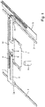
- the essential components of a microplate reader are in figure 1 shown as an example.
- the microplate reader comprises a receiving device 1 for receiving a microplate, which serves as a sample carrier.
- the recording 1 is referred to below as a plate carrier. It holds a microplate on its edge and secures it at the corners against slipping sideways. Additional, in figure 1 not shown holding means such as a spring or a spring mechanism may be provided, which additionally secures the microplate in the plate carrier 1.
- the plate carrier 1 is held on a carriage 2a of a linear guide 2 which is linearly movable in the X-direction.
- the linear guide 2 is in turn attached to two lateral linear guides 3 via two linearly movable carriages 3a in the Y-direction.
- the plate carrier 1, and with it a microplate accommodated therein, can be positioned freely in the X and Y directions via the linear guides 2, 3.
- an optical detector 9 is arranged below the plate carrier 1, an optical detector 9 is arranged below the plate carrier 1, an optical detector 9 is arranged below the plate carrier 1, an optical detector 9 is arranged below the plate carrier 1, an optical detector 9 is arranged below the plate carrier 1, an optical detector 9 is arranged below the plate carrier 1, an optical detector 9 is arranged below the plate carrier 1, an optical detector 9 is arranged below the plate carrier 1, an optical detector 9 is arranged below the plate carrier 1, an optical detector 9 is arranged below the plate carrier 1, an optical detector 9 is arranged.
- the optical detector 9 can be a photomultiplier, for example,
- a photomultiplier instead of a photomultiplier, other optical detectors such as a photocell, a CMOS or CCD sensor, a microchannel plate (MCP), a photodiode, a photoresistor, etc., and in particular a camera can also be used for image recording.
- CMOS or CCD sensor a CMOS or CCD sensor
- MCP microchannel plate
- a photodiode a photoresistor, etc.
- a camera can also be used for image recording.
- the microplate is moved via the positioning system formed by the linear guides 2, 3 in such a way that the individual wells of the microplate are located one after the other at the measurement position defined by the detection area of the optical detector 9.
- the measuring position is defined in FIG. 1 by the axis of the optical detector 9, with which the optical radiation perpendicular to the microplate is measured from below.
- the optical detector is arranged above the microplate and measures the optical radiation above the microplate.
- an interface device On the side of the plate carrier 1 facing the carriage 2a is an interface device with an electrical interface 4 for power supply and data transmission as well as a hose connection 5, which is used to supply media to an accessory device inserted into the plate carrier 1.
- the electrical interface 4 is realized by electrical contact surfaces which are arranged behind the receiving position of a microplate. The contact surfaces are arranged in such a way that they have no effect when using a normal microplate.
- the hose connection 5 is also arranged behind the receiving position of the microplate.
- the interface device 4, 5 is connected to corresponding systems of the microplate reader, ie a control device and a medium supply device, by a multi-wire cable and a hose 6.
- An accessory device of suitable dimensions can be inserted into the plate carrier 1 either in addition to a microplate or instead of a microplate and connected to the microplate reader via the interface device 4, 5.
- Such an accessory device can be used to implement accessory functions that can be used, for example, for a specific measurement or for cleaning, calibrating or qualifying the microplate reader.
- FIG 2 such an accessory device is shown as an example, which is inserted into the plate carrier 1 instead of a microplate.
- the accessory device has contact springs 10 on its rear-facing side, which produce an electrical connection to the contact surfaces of the electrical interface 4 when they are inserted into the plate carrier 1 .
- the housing 11 of the accessory device is designed to fit snugly in the plate carrier 1 and the contact springs 10 forming a mating point for the interface 4 are aligned at the appropriate position.
- the accessory device contains a printed circuit board 13 with UV light sources 12 arranged at the corners, which are controlled by control electronics housed on the printed circuit board 13 and are electrically supplied and activated via the electrical interface 4 .
- the UV light sources are used to kill any germs in the microplate compartment of the microplate reader and thus disinfect the microplate compartment.
- UV light sources 12 instead of or in addition to the UV light sources 12, however, various sensors such as a temperature sensor, a humidity sensor, a position or acceleration sensor, a gas sensor, an optical sensor for measuring an excitation light source of the microplate reader, touch or proximity sensors or a Fan or a vacuum cleaner can be arranged.
- sensors such as a temperature sensor, a humidity sensor, a position or acceleration sensor, a gas sensor, an optical sensor for measuring an excitation light source of the microplate reader, touch or proximity sensors or a Fan or a vacuum cleaner can be arranged.
- the accessory device can also be designed in such a way that it can be inserted into the plate carrier 1 together with a microplate.
- the accessory device can have additional functions such as a storage device, a heater, an illumination device for the microplate, measuring or excitation electrodes or a shaking device for the microplate.
- FIG 3 a block diagram of the microplate reader is shown again. It comprises a receiving device 1 for microplates, with an interface device 16 having an electrical interface 4 and a media interface 5 being arranged on the receiving device 1 .
- An accessory device 20 is inserted into the receiving device 1 .
- This has a counterpart 21 that matches the interface device 16 and that uses the interface device 16 to create an electrical connection and a media connection between the microplate reader and the accessory device 20 .
- the accessory device 20 can be inserted into the receiving device together with or instead of a microplate.
- the accessory device 20 has a control and measurement circuit 22, which can be implemented by a microprocessor, for example.
- the control and measurement circuit 22 is connected to one or more sensors 23, reads their measured values and transmits them via the interface device 16 to the microplate reader.
- the control and measurement circuit 22 is connected to one or more actuators 24 .
- actuators can be, for example, a heater, a lighting device, a UV light source, electrodes or an actuator such as a valve or a metering pump, a vacuum cleaning device or a fan.
- sensors can be a temperature sensor, a humidity sensor, a position or acceleration sensor, a gas sensor, an optical sensor, a touch or proximity sensor or the like.
- the accessory device 20 has a media distribution device 25 which is connected to the media connection 5 of the interface device and which forwards the medium made available at the media connection 5 to individual wells of a microplate in an application-specific manner.
- the microplate reader has a programmable control device 15 of a type known per se, such as a control computer, controller, CPU, FPGA, microcontroller or the like.
- the control device is connected to the optical detector 9 and receives and processes its measured values.
- the control device 15 is connected to drive motors 17a, 17b, with which the figure 1 shown linear guides 2, 3 are driven.
- the control device 15 can thus position a microplate inserted in the removal device 1 such that the individual wells of the microplate are successively brought into the detection area of the detector 9 and the microplate can thus be read well by well.
- control device 15 is connected to interface device 16 and uses it to receive data signals from control and measurement circuit 22 or send command signals to control and measurement circuit 22.
- control device 15 is connected to a medium supply device 18 and controls it.
- the medium supply device 18 is connected to the media distribution device 25 of the accessory device via a hose line and the media connection 5 .
- Medium supply device 18 provides one or more media for the distribution device 25 of the accessory device 20 via the media connection 5 of the interface device 16 .
- the medium supply device 18 can be implemented, for example, by a media pump and a media container connected to it.
- an accessory device is shown as an example, which is inserted into the plate carrier 1 together with a 12-well microplate.
- the accessory device is placed on the microplate like a lid. Matching each microplate well, the accessory has an opening through which the measurement can take place unhindered.
- the accessory device has a cavity between a top wall 30 and a bottom wall 31 over which the medium can spread.
- the medium is introduced into said cavity via a hose connection 32 that fits the interface device of the microplate reader and flows out through at least one nozzle 33 for each microplate well. This ensures that the introduced atmosphere reaches the sample directly and the point in time of the gas supply is specified exactly for all samples, in contrast to the gas introduction into the entire incubator.
- the gas sensor represents an expedient addition to media distribution and can be plugged into a corresponding data and power connection of the interface device in order to measure a gas concentration in the immediate vicinity of the microplate.
- figure 5 shows in a further exemplary embodiment, as an exploded drawing, the structure of an accessory device which accommodates a microplate and is inserted into the plate carrier together with the microplate.
- the accessory device is used to shake the sample to mix the liquid(s) in the sample.
- the shaking of samples caused by movement of the plate carrier is typically limited in the shaking frequency to a few hundred RPM by the inertia of the plate carrier and the moving parts.
- the accessory device shown is inserted together with the microplate in the plate carrier, which moves the microplate relative to the plate carrier with a vibration motor.
- the accessory device shown allows measurement from above, eg fluorescence or luminescence.
- the accessory device includes a frame 20 which fits into the plate carrier of the microplate reader.
- the mount 22 for the microplate is mounted on these via an oscillating suspension, in the example via springs 21 .
- the recording is preferably built very light, so it has a low mechanical inertia.
- a printed circuit board 23 carrying a controller and a vibration motor 24 is mounted on the underside of the receptacle.
- the printed circuit board is connected via a cable connection to a contacting device 25 that matches the interface device of the plate carrier and is mounted on the frame in such a way that a connection is established when it is placed in the plate carrier.
- figure 6 shows an accessory device in the form of a printed circuit board with 96 LEDs, which are placed in the plate carrier together with the microplate in order to obtain an individual irradiation of each well of a 96-well microplate.
- the supply and control of the LEDs is achieved by plug-in contacts via the interface of the plate carrier.
- all or individual wells a 96-well microplate can be illuminated in a targeted manner, for example to support biological or photochemical processes taking place therein, and can be switched off individually for a measurement on the relevant well.
Landscapes
- Health & Medical Sciences (AREA)
- Chemical & Material Sciences (AREA)
- Analytical Chemistry (AREA)
- General Health & Medical Sciences (AREA)
- Physics & Mathematics (AREA)
- General Physics & Mathematics (AREA)
- Biochemistry (AREA)
- Life Sciences & Earth Sciences (AREA)
- Immunology (AREA)
- Pathology (AREA)
- Clinical Laboratory Science (AREA)
- Chemical Kinetics & Catalysis (AREA)
- Nuclear Medicine, Radiotherapy & Molecular Imaging (AREA)
- Hematology (AREA)
- Spectroscopy & Molecular Physics (AREA)
- Investigating, Analyzing Materials By Fluorescence Or Luminescence (AREA)
- Automatic Analysis And Handling Materials Therefor (AREA)
- Investigating Or Analysing Materials By Optical Means (AREA)
Applications Claiming Priority (1)
| Application Number | Priority Date | Filing Date | Title |
|---|---|---|---|
| DE102020128003.3A DE102020128003A1 (de) | 2020-10-23 | 2020-10-23 | Mikroplatten-Lesegerät |
Publications (3)
| Publication Number | Publication Date |
|---|---|
| EP3988924A2 true EP3988924A2 (fr) | 2022-04-27 |
| EP3988924A3 EP3988924A3 (fr) | 2022-07-20 |
| EP3988924B1 EP3988924B1 (fr) | 2023-11-29 |
Family
ID=73747495
Family Applications (1)
| Application Number | Title | Priority Date | Filing Date |
|---|---|---|---|
| EP21199753.1A Active EP3988924B1 (fr) | 2020-10-23 | 2021-09-29 | Combinaison d'un lecteur de microplaques avec un appareil accessoire |
Country Status (3)
| Country | Link |
|---|---|
| US (1) | US12152987B2 (fr) |
| EP (1) | EP3988924B1 (fr) |
| DE (1) | DE102020128003A1 (fr) |
Families Citing this family (6)
| Publication number | Priority date | Publication date | Assignee | Title |
|---|---|---|---|---|
| WO2020072463A1 (fr) * | 2018-10-01 | 2020-04-09 | Elemental Machines, Inc. | Procédé et appareil de détection locale |
| DE102021112938A1 (de) | 2021-05-19 | 2022-11-24 | Bmg Labtech Gmbh | Mikroplatten-Lesegerät |
| US11958053B2 (en) * | 2021-09-21 | 2024-04-16 | The Government of the United States of America, as represented by the Secretary of Homeland Security | Media holder for sample preparation |
| EP4393598A1 (fr) * | 2022-12-27 | 2024-07-03 | TECAN Trading AG | Plaque d'équilibrage de température pour un lecteur de microplaque et lecteur de microplaque doté d'une telle plaque d'équilibrage de température |
| CN118091102B (zh) * | 2024-01-04 | 2024-08-16 | 安徽省血吸虫病防治研究所 | 一种血吸虫抗体智能检测仪器及其使用方法 |
| CN119104709B (zh) * | 2024-09-02 | 2026-03-17 | 江西博美莱生物科技有限公司 | 一种转移因子的检测设备及方法 |
Family Cites Families (41)
| Publication number | Priority date | Publication date | Assignee | Title |
|---|---|---|---|---|
| US4225410A (en) | 1978-12-04 | 1980-09-30 | Technicon Instruments Corporation | Integrated array of electrochemical sensors |
| US5849486A (en) * | 1993-11-01 | 1998-12-15 | Nanogen, Inc. | Methods for hybridization analysis utilizing electrically controlled hybridization |
| US6399023B1 (en) * | 1996-04-16 | 2002-06-04 | Caliper Technologies Corp. | Analytical system and method |
| DE19646505A1 (de) | 1996-11-12 | 1998-05-14 | Itt Ind Gmbh Deutsche | Vorrichtung zur Durchführung von Untersuchungen an Zellproben und dergleichen |
| DE29906382U1 (de) | 1998-04-14 | 1999-09-30 | BioTul/Bio Instruments GmbH, 80339 München | Probenträger mit Kennzeichnung |
| AU6075100A (en) * | 1999-07-07 | 2001-01-30 | Ljl Biosystems, Inc. | Light detection device |
| US6358387B1 (en) * | 2000-03-27 | 2002-03-19 | Caliper Technologies Corporation | Ultra high throughput microfluidic analytical systems and methods |
| WO2002072423A1 (fr) * | 2001-03-09 | 2002-09-19 | Biomicro Systems, Inc. | Couvercle de microplaque |
| DE10137954A1 (de) | 2001-08-07 | 2003-06-18 | Eidgenoess Tech Hochschule | System zur Überwachung von biologischen und chemischen Prozessen |
| US6822741B2 (en) | 2001-09-07 | 2004-11-23 | Wallac Oy | Optical instrument and process for measurement of samples |
| AU2003241450A1 (en) | 2002-05-13 | 2003-12-02 | Scinomix | Automated processing system and method of using same |
| WO2005009126A1 (fr) * | 2003-07-23 | 2005-02-03 | Essen Instruments, Inc. | Systèmes d'analyse de prélèvements biologiques |
| US8658349B2 (en) * | 2006-07-13 | 2014-02-25 | Seahorse Bioscience | Cell analysis apparatus and method |
| US7187286B2 (en) | 2004-03-19 | 2007-03-06 | Applera Corporation | Methods and systems for using RFID in biological field |
| JP2005345378A (ja) * | 2004-06-04 | 2005-12-15 | Nippon Sheet Glass Co Ltd | 光検出装置 |
| TWI245116B (en) * | 2004-12-21 | 2005-12-11 | Kaiwood Technology Co Ltd | Detection array luminometer |
| CH698317B1 (de) | 2005-07-11 | 2009-07-15 | Tecan Trading Ag | Mikroplattenreader mit intelligentem Filterschieber. |
| US7692783B2 (en) * | 2006-02-13 | 2010-04-06 | Pacific Biosciences Of California | Methods and systems for simultaneous real-time monitoring of optical signals from multiple sources |
| US20070248494A1 (en) | 2006-04-24 | 2007-10-25 | Mokelke Michael F | Multi-Mode Modular Method and Apparatus for Micro-titer Plate Analysis |
| US20080044879A1 (en) * | 2006-08-17 | 2008-02-21 | The Charles Stark Draper Laboratory, Inc. | Systems and methods of voltage-gated ion channel assays |
| FI20075439A0 (fi) * | 2007-06-12 | 2007-06-12 | Wallac Oy | Automatisoitu instrumentointi ja menetelmä näytteiden mittaamiseksi |
| US20090104078A1 (en) * | 2007-10-18 | 2009-04-23 | Matrix Technologies Corporation | Apparatus and method for dispensing small volume liquid samples |
| JP2009121818A (ja) | 2007-11-09 | 2009-06-04 | Olympus Corp | 分析装置 |
| US7919062B2 (en) | 2008-03-20 | 2011-04-05 | Corning Incorporated | Modular microfluidic system and method for building a modular microfludic system |
| DE102008025992B4 (de) * | 2008-05-30 | 2011-01-27 | Siemens Healthcare Diagnostics Gmbh | Titerplatte und Verfahren zur Detektion eines Analyten |
| US20100184616A1 (en) * | 2009-01-20 | 2010-07-22 | Bio-Rad Laboratories, Inc. | Spatially controlled illumination of biological sample array through wedge-shaped support |
| CH703700A2 (de) * | 2010-09-08 | 2012-03-15 | Tecan Trading Ag | Kontrolle der Gasatmosphäre in Mikroplatten-Readern. |
| US8692987B2 (en) | 2011-08-09 | 2014-04-08 | Artel, Inc. | Artifact apparatus to mimic reflection losses of solution-filled microtiter plate readers and related uses thereof |
| WO2013039738A1 (fr) | 2011-09-12 | 2013-03-21 | Corning Incorporated | Appareil pour dosages sans marqueur régulés en température |
| CH706326A2 (de) | 2012-03-14 | 2013-09-30 | Tecan Trading Ag | Verfahren und Mikroplatten-Reader zum Untersuchung von biologischen Zellen oder Zellkulturen. |
| US8858886B1 (en) * | 2013-05-08 | 2014-10-14 | Agilent Technologies, Inc. | Scanning system with interchangeable optical cartridges for fluorescence measurements |
| US10641766B2 (en) | 2013-07-12 | 2020-05-05 | Nowdiagnostics, Inc. | Universal rapid diagnostic test reader with trans-visual sensitivity |
| CH708820A1 (de) * | 2013-11-07 | 2015-05-15 | Tecan Trading Ag | Inkubationskassette. |
| DK3177920T3 (da) * | 2014-08-05 | 2021-06-21 | Sanwa Biotech Ltd | På-stedet-diagnosesystem og fremgangsmåde dertil |
| US9784685B2 (en) * | 2014-12-10 | 2017-10-10 | Molecular Devices, Inc. | Liquid and plate sensors for microplate injector system |
| US10712356B2 (en) * | 2015-04-21 | 2020-07-14 | General Automation Lab Technologies Inc. | Apparatus and method for picking biological sample |
| EP3311163B1 (fr) | 2015-06-19 | 2020-08-05 | The Regents of the University of California | Lecteur de micro-plaque pour essai elisa |
| US20170212050A1 (en) | 2016-01-22 | 2017-07-27 | Ionfield Holdings, Llc | Method for calibrating and using calibration of microplates |
| US10116356B2 (en) | 2016-11-07 | 2018-10-30 | Molecular Devices (Austria) GmbH | System and method for operating a microplate reader |
| US11200698B2 (en) * | 2017-06-01 | 2021-12-14 | Germaine Laboratories, Inc. | Devices and systems for data-based analysis of objects |
| DE102018200646A1 (de) | 2018-01-16 | 2019-07-18 | Berthold Technologies Gmbh & Co. Kg | System zum Messen optischer Eigenschaften von Proben |
-
2020
- 2020-10-23 DE DE102020128003.3A patent/DE102020128003A1/de active Pending
-
2021
- 2021-09-29 EP EP21199753.1A patent/EP3988924B1/fr active Active
- 2021-10-18 US US17/503,732 patent/US12152987B2/en active Active
Also Published As
| Publication number | Publication date |
|---|---|
| EP3988924A3 (fr) | 2022-07-20 |
| US20220128470A1 (en) | 2022-04-28 |
| EP3988924B1 (fr) | 2023-11-29 |
| US12152987B2 (en) | 2024-11-26 |
| DE102020128003A1 (de) | 2020-12-31 |
Similar Documents
| Publication | Publication Date | Title |
|---|---|---|
| EP3988924B1 (fr) | Combinaison d'un lecteur de microplaques avec un appareil accessoire | |
| DE69832065T2 (de) | Automat für mikrobiologische tests und verfahren dafür | |
| DE60115860T2 (de) | Mikroarray-dosiervorrichtungen mit sensoren | |
| EP2428792B1 (fr) | Lecteur à microplaquettes doté d'une atmosphère gazeuse contrôlée, procédé correspondant et utilisation de celui-ci | |
| DE60000386T2 (de) | Adapter für eine pipette, pipette zur absorptionsmessung, verfahren und vorrichtung zur absorptionsmessung | |
| DE602004011584T2 (de) | Automatischer Analysator | |
| DE60128550T2 (de) | Verfahren und gerät zur automatischen pin-detektion in instrumenten zur erzeugung von mikroarrays | |
| EP3759502B1 (fr) | Appareil de mesure pour un appareil automatique de laboratoire de mesure d'un objet, objet pour ledit appareil de mesure et procédé de mesure | |
| EP2283368A2 (fr) | Appareil pour l'analyse | |
| JPS63500114A (ja) | 標本のトレイ組立体保管装置 | |
| DE60307424T2 (de) | Vorrichtung zur automatisierten analyse flüssiger proben | |
| EP3839476B1 (fr) | Dispositif et procédé de détermination d'une position et/ou d'une extension d'une goutte | |
| EP3839481B1 (fr) | Procédé de réduction de l'évaporation de liquide à partir de puits d'une microplaque | |
| DE19941167A1 (de) | Abbildungsvorrichtung | |
| WO2014023300A1 (fr) | Dispositif de détermination d'un échantillon pour essai, appareil de mesure et kit pourvu de modules pour échantillon | |
| EP1511989A1 (fr) | Systeme de mesure fondee sur la fluorescence | |
| EP1912741A1 (fr) | Systeme de titrage | |
| EP2669011B1 (fr) | Procédé et dispositif de projection d'image destinés à soutenir la préparation pratique d'échantillons MALDI | |
| DE102011075039A9 (de) | Stanzvorrichtung mit beleuchteter Aufnahmeplatte | |
| DE60309255T2 (de) | Abbildung und Entnahme von Gel | |
| DE102010052976A1 (de) | Unterstützung der händischen Präparation von Proben auf einem Probenträger für eine Ionisierung mit matrix-unterstützter Laserdesorption | |
| DE3913632C2 (de) | Titriergerät | |
| DE102016225817B4 (de) | Verfahren und System für Messungen im Hochdurchsatz-Screening mit hoher Zeitauflösung | |
| DE10132761B4 (de) | Klimatisierbare Probenkammer und Verfahren zur Klimatisierung der Umgebung von Proben | |
| DE10149879A1 (de) | Vorrichtung zur spektralphotometrischen Analyse von flüssigen Medien |
Legal Events
| Date | Code | Title | Description |
|---|---|---|---|
| PUAI | Public reference made under article 153(3) epc to a published international application that has entered the european phase |
Free format text: ORIGINAL CODE: 0009012 |
|
| STAA | Information on the status of an ep patent application or granted ep patent |
Free format text: STATUS: THE APPLICATION HAS BEEN PUBLISHED |
|
| AK | Designated contracting states |
Kind code of ref document: A2 Designated state(s): AL AT BE BG CH CY CZ DE DK EE ES FI FR GB GR HR HU IE IS IT LI LT LU LV MC MK MT NL NO PL PT RO RS SE SI SK SM TR |
|
| PUAL | Search report despatched |
Free format text: ORIGINAL CODE: 0009013 |
|
| AK | Designated contracting states |
Kind code of ref document: A3 Designated state(s): AL AT BE BG CH CY CZ DE DK EE ES FI FR GB GR HR HU IE IS IT LI LT LU LV MC MK MT NL NO PL PT RO RS SE SI SK SM TR |
|
| RIC1 | Information provided on ipc code assigned before grant |
Ipc: G01N 35/00 20060101ALI20220614BHEP Ipc: G01N 21/03 20060101ALI20220614BHEP Ipc: G01N 35/04 20060101ALI20220614BHEP Ipc: G01N 21/64 20060101ALI20220614BHEP Ipc: G01N 21/25 20060101AFI20220614BHEP |
|
| STAA | Information on the status of an ep patent application or granted ep patent |
Free format text: STATUS: REQUEST FOR EXAMINATION WAS MADE |
|
| 17P | Request for examination filed |
Effective date: 20230118 |
|
| RBV | Designated contracting states (corrected) |
Designated state(s): AL AT BE BG CH CY CZ DE DK EE ES FI FR GB GR HR HU IE IS IT LI LT LU LV MC MK MT NL NO PL PT RO RS SE SI SK SM TR |
|
| GRAP | Despatch of communication of intention to grant a patent |
Free format text: ORIGINAL CODE: EPIDOSNIGR1 |
|
| STAA | Information on the status of an ep patent application or granted ep patent |
Free format text: STATUS: GRANT OF PATENT IS INTENDED |
|
| INTG | Intention to grant announced |
Effective date: 20230804 |
|
| GRAS | Grant fee paid |
Free format text: ORIGINAL CODE: EPIDOSNIGR3 |
|
| GRAA | (expected) grant |
Free format text: ORIGINAL CODE: 0009210 |
|
| STAA | Information on the status of an ep patent application or granted ep patent |
Free format text: STATUS: THE PATENT HAS BEEN GRANTED |
|
| P01 | Opt-out of the competence of the unified patent court (upc) registered |
Effective date: 20231009 |
|
| AK | Designated contracting states |
Kind code of ref document: B1 Designated state(s): AL AT BE BG CH CY CZ DE DK EE ES FI FR GB GR HR HU IE IS IT LI LT LU LV MC MK MT NL NO PL PT RO RS SE SI SK SM TR |
|
| REG | Reference to a national code |
Ref country code: GB Ref legal event code: FG4D Free format text: NOT ENGLISH |
|
| REG | Reference to a national code |
Ref country code: CH Ref legal event code: EP |
|
| REG | Reference to a national code |
Ref country code: DE Ref legal event code: R096 Ref document number: 502021002063 Country of ref document: DE |
|
| REG | Reference to a national code |
Ref country code: IE Ref legal event code: FG4D Free format text: LANGUAGE OF EP DOCUMENT: GERMAN |
|
| REG | Reference to a national code |
Ref country code: LT Ref legal event code: MG9D |
|
| REG | Reference to a national code |
Ref country code: NL Ref legal event code: MP Effective date: 20231129 |
|
| PG25 | Lapsed in a contracting state [announced via postgrant information from national office to epo] |
Ref country code: GR Free format text: LAPSE BECAUSE OF FAILURE TO SUBMIT A TRANSLATION OF THE DESCRIPTION OR TO PAY THE FEE WITHIN THE PRESCRIBED TIME-LIMIT Effective date: 20240301 |
|
| PG25 | Lapsed in a contracting state [announced via postgrant information from national office to epo] |
Ref country code: IS Free format text: LAPSE BECAUSE OF FAILURE TO SUBMIT A TRANSLATION OF THE DESCRIPTION OR TO PAY THE FEE WITHIN THE PRESCRIBED TIME-LIMIT Effective date: 20240329 |
|
| PG25 | Lapsed in a contracting state [announced via postgrant information from national office to epo] |
Ref country code: LT Free format text: LAPSE BECAUSE OF FAILURE TO SUBMIT A TRANSLATION OF THE DESCRIPTION OR TO PAY THE FEE WITHIN THE PRESCRIBED TIME-LIMIT Effective date: 20231129 |
|
| PG25 | Lapsed in a contracting state [announced via postgrant information from national office to epo] |
Ref country code: ES Free format text: LAPSE BECAUSE OF FAILURE TO SUBMIT A TRANSLATION OF THE DESCRIPTION OR TO PAY THE FEE WITHIN THE PRESCRIBED TIME-LIMIT Effective date: 20231129 |
|
| PG25 | Lapsed in a contracting state [announced via postgrant information from national office to epo] |
Ref country code: LT Free format text: LAPSE BECAUSE OF FAILURE TO SUBMIT A TRANSLATION OF THE DESCRIPTION OR TO PAY THE FEE WITHIN THE PRESCRIBED TIME-LIMIT Effective date: 20231129 Ref country code: IS Free format text: LAPSE BECAUSE OF FAILURE TO SUBMIT A TRANSLATION OF THE DESCRIPTION OR TO PAY THE FEE WITHIN THE PRESCRIBED TIME-LIMIT Effective date: 20240329 Ref country code: GR Free format text: LAPSE BECAUSE OF FAILURE TO SUBMIT A TRANSLATION OF THE DESCRIPTION OR TO PAY THE FEE WITHIN THE PRESCRIBED TIME-LIMIT Effective date: 20240301 Ref country code: ES Free format text: LAPSE BECAUSE OF FAILURE TO SUBMIT A TRANSLATION OF THE DESCRIPTION OR TO PAY THE FEE WITHIN THE PRESCRIBED TIME-LIMIT Effective date: 20231129 Ref country code: BG Free format text: LAPSE BECAUSE OF FAILURE TO SUBMIT A TRANSLATION OF THE DESCRIPTION OR TO PAY THE FEE WITHIN THE PRESCRIBED TIME-LIMIT Effective date: 20240229 |
|
| PG25 | Lapsed in a contracting state [announced via postgrant information from national office to epo] |
Ref country code: NL Free format text: LAPSE BECAUSE OF FAILURE TO SUBMIT A TRANSLATION OF THE DESCRIPTION OR TO PAY THE FEE WITHIN THE PRESCRIBED TIME-LIMIT Effective date: 20231129 |
|
| PG25 | Lapsed in a contracting state [announced via postgrant information from national office to epo] |
Ref country code: SE Free format text: LAPSE BECAUSE OF FAILURE TO SUBMIT A TRANSLATION OF THE DESCRIPTION OR TO PAY THE FEE WITHIN THE PRESCRIBED TIME-LIMIT Effective date: 20231129 Ref country code: RS Free format text: LAPSE BECAUSE OF FAILURE TO SUBMIT A TRANSLATION OF THE DESCRIPTION OR TO PAY THE FEE WITHIN THE PRESCRIBED TIME-LIMIT Effective date: 20231129 Ref country code: PL Free format text: LAPSE BECAUSE OF FAILURE TO SUBMIT A TRANSLATION OF THE DESCRIPTION OR TO PAY THE FEE WITHIN THE PRESCRIBED TIME-LIMIT Effective date: 20231129 Ref country code: NO Free format text: LAPSE BECAUSE OF FAILURE TO SUBMIT A TRANSLATION OF THE DESCRIPTION OR TO PAY THE FEE WITHIN THE PRESCRIBED TIME-LIMIT Effective date: 20240229 Ref country code: NL Free format text: LAPSE BECAUSE OF FAILURE TO SUBMIT A TRANSLATION OF THE DESCRIPTION OR TO PAY THE FEE WITHIN THE PRESCRIBED TIME-LIMIT Effective date: 20231129 Ref country code: LV Free format text: LAPSE BECAUSE OF FAILURE TO SUBMIT A TRANSLATION OF THE DESCRIPTION OR TO PAY THE FEE WITHIN THE PRESCRIBED TIME-LIMIT Effective date: 20231129 Ref country code: HR Free format text: LAPSE BECAUSE OF FAILURE TO SUBMIT A TRANSLATION OF THE DESCRIPTION OR TO PAY THE FEE WITHIN THE PRESCRIBED TIME-LIMIT Effective date: 20231129 |
|
| PG25 | Lapsed in a contracting state [announced via postgrant information from national office to epo] |
Ref country code: DK Free format text: LAPSE BECAUSE OF FAILURE TO SUBMIT A TRANSLATION OF THE DESCRIPTION OR TO PAY THE FEE WITHIN THE PRESCRIBED TIME-LIMIT Effective date: 20231129 |
|
| PG25 | Lapsed in a contracting state [announced via postgrant information from national office to epo] |
Ref country code: CZ Free format text: LAPSE BECAUSE OF FAILURE TO SUBMIT A TRANSLATION OF THE DESCRIPTION OR TO PAY THE FEE WITHIN THE PRESCRIBED TIME-LIMIT Effective date: 20231129 |
|
| PG25 | Lapsed in a contracting state [announced via postgrant information from national office to epo] |
Ref country code: SK Free format text: LAPSE BECAUSE OF FAILURE TO SUBMIT A TRANSLATION OF THE DESCRIPTION OR TO PAY THE FEE WITHIN THE PRESCRIBED TIME-LIMIT Effective date: 20231129 |
|
| PG25 | Lapsed in a contracting state [announced via postgrant information from national office to epo] |
Ref country code: SM Free format text: LAPSE BECAUSE OF FAILURE TO SUBMIT A TRANSLATION OF THE DESCRIPTION OR TO PAY THE FEE WITHIN THE PRESCRIBED TIME-LIMIT Effective date: 20231129 Ref country code: SK Free format text: LAPSE BECAUSE OF FAILURE TO SUBMIT A TRANSLATION OF THE DESCRIPTION OR TO PAY THE FEE WITHIN THE PRESCRIBED TIME-LIMIT Effective date: 20231129 Ref country code: RO Free format text: LAPSE BECAUSE OF FAILURE TO SUBMIT A TRANSLATION OF THE DESCRIPTION OR TO PAY THE FEE WITHIN THE PRESCRIBED TIME-LIMIT Effective date: 20231129 Ref country code: IT Free format text: LAPSE BECAUSE OF FAILURE TO SUBMIT A TRANSLATION OF THE DESCRIPTION OR TO PAY THE FEE WITHIN THE PRESCRIBED TIME-LIMIT Effective date: 20231129 Ref country code: EE Free format text: LAPSE BECAUSE OF FAILURE TO SUBMIT A TRANSLATION OF THE DESCRIPTION OR TO PAY THE FEE WITHIN THE PRESCRIBED TIME-LIMIT Effective date: 20231129 Ref country code: DK Free format text: LAPSE BECAUSE OF FAILURE TO SUBMIT A TRANSLATION OF THE DESCRIPTION OR TO PAY THE FEE WITHIN THE PRESCRIBED TIME-LIMIT Effective date: 20231129 Ref country code: CZ Free format text: LAPSE BECAUSE OF FAILURE TO SUBMIT A TRANSLATION OF THE DESCRIPTION OR TO PAY THE FEE WITHIN THE PRESCRIBED TIME-LIMIT Effective date: 20231129 |
|
| PG25 | Lapsed in a contracting state [announced via postgrant information from national office to epo] |
Ref country code: PT Free format text: LAPSE BECAUSE OF FAILURE TO SUBMIT A TRANSLATION OF THE DESCRIPTION OR TO PAY THE FEE WITHIN THE PRESCRIBED TIME-LIMIT Effective date: 20240401 |
|
| PG25 | Lapsed in a contracting state [announced via postgrant information from national office to epo] |
Ref country code: PT Free format text: LAPSE BECAUSE OF FAILURE TO SUBMIT A TRANSLATION OF THE DESCRIPTION OR TO PAY THE FEE WITHIN THE PRESCRIBED TIME-LIMIT Effective date: 20240401 |
|
| REG | Reference to a national code |
Ref country code: DE Ref legal event code: R097 Ref document number: 502021002063 Country of ref document: DE |
|
| PLBE | No opposition filed within time limit |
Free format text: ORIGINAL CODE: 0009261 |
|
| STAA | Information on the status of an ep patent application or granted ep patent |
Free format text: STATUS: NO OPPOSITION FILED WITHIN TIME LIMIT |
|
| PG25 | Lapsed in a contracting state [announced via postgrant information from national office to epo] |
Ref country code: SI Free format text: LAPSE BECAUSE OF FAILURE TO SUBMIT A TRANSLATION OF THE DESCRIPTION OR TO PAY THE FEE WITHIN THE PRESCRIBED TIME-LIMIT Effective date: 20231129 |
|
| PG25 | Lapsed in a contracting state [announced via postgrant information from national office to epo] |
Ref country code: SI Free format text: LAPSE BECAUSE OF FAILURE TO SUBMIT A TRANSLATION OF THE DESCRIPTION OR TO PAY THE FEE WITHIN THE PRESCRIBED TIME-LIMIT Effective date: 20231129 |
|
| 26N | No opposition filed |
Effective date: 20240830 |
|
| PG25 | Lapsed in a contracting state [announced via postgrant information from national office to epo] |
Ref country code: MC Free format text: LAPSE BECAUSE OF FAILURE TO SUBMIT A TRANSLATION OF THE DESCRIPTION OR TO PAY THE FEE WITHIN THE PRESCRIBED TIME-LIMIT Effective date: 20231129 |
|
| PG25 | Lapsed in a contracting state [announced via postgrant information from national office to epo] |
Ref country code: LU Free format text: LAPSE BECAUSE OF NON-PAYMENT OF DUE FEES Effective date: 20240929 |
|
| REG | Reference to a national code |
Ref country code: BE Ref legal event code: MM Effective date: 20240930 |
|
| PG25 | Lapsed in a contracting state [announced via postgrant information from national office to epo] |
Ref country code: BE Free format text: LAPSE BECAUSE OF NON-PAYMENT OF DUE FEES Effective date: 20240930 |
|
| PG25 | Lapsed in a contracting state [announced via postgrant information from national office to epo] |
Ref country code: IE Free format text: LAPSE BECAUSE OF NON-PAYMENT OF DUE FEES Effective date: 20240929 |
|
| REG | Reference to a national code |
Ref country code: CH Ref legal event code: U11 Free format text: ST27 STATUS EVENT CODE: U-0-0-U10-U11 (AS PROVIDED BY THE NATIONAL OFFICE) Effective date: 20251001 |
|
| PG25 | Lapsed in a contracting state [announced via postgrant information from national office to epo] |
Ref country code: FI Free format text: LAPSE BECAUSE OF FAILURE TO SUBMIT A TRANSLATION OF THE DESCRIPTION OR TO PAY THE FEE WITHIN THE PRESCRIBED TIME-LIMIT Effective date: 20231129 |
|
| PGFP | Annual fee paid to national office [announced via postgrant information from national office to epo] |
Ref country code: DE Payment date: 20250730 Year of fee payment: 5 |
|
| PGFP | Annual fee paid to national office [announced via postgrant information from national office to epo] |
Ref country code: GB Payment date: 20250923 Year of fee payment: 5 |
|
| PGFP | Annual fee paid to national office [announced via postgrant information from national office to epo] |
Ref country code: AT Payment date: 20251020 Year of fee payment: 5 Ref country code: FR Payment date: 20250926 Year of fee payment: 5 |
|
| PGFP | Annual fee paid to national office [announced via postgrant information from national office to epo] |
Ref country code: CH Payment date: 20251001 Year of fee payment: 5 |
|
| PG25 | Lapsed in a contracting state [announced via postgrant information from national office to epo] |
Ref country code: CY Free format text: LAPSE BECAUSE OF FAILURE TO SUBMIT A TRANSLATION OF THE DESCRIPTION OR TO PAY THE FEE WITHIN THE PRESCRIBED TIME-LIMIT; INVALID AB INITIO Effective date: 20210929 |
|
| PG25 | Lapsed in a contracting state [announced via postgrant information from national office to epo] |
Ref country code: HU Free format text: LAPSE BECAUSE OF FAILURE TO SUBMIT A TRANSLATION OF THE DESCRIPTION OR TO PAY THE FEE WITHIN THE PRESCRIBED TIME-LIMIT; INVALID AB INITIO Effective date: 20210929 |