EP3990302B1 - Procédé et dispositif de commande pour le fonctionnement d'un casque de réalité virtuelle dans un véhicule - Google Patents
Procédé et dispositif de commande pour le fonctionnement d'un casque de réalité virtuelle dans un véhicule Download PDFInfo
- Publication number
- EP3990302B1 EP3990302B1 EP20772090.5A EP20772090A EP3990302B1 EP 3990302 B1 EP3990302 B1 EP 3990302B1 EP 20772090 A EP20772090 A EP 20772090A EP 3990302 B1 EP3990302 B1 EP 3990302B1
- Authority
- EP
- European Patent Office
- Prior art keywords
- vehicle
- virtual reality
- reality headset
- virtual
- capture device
- Prior art date
- Legal status (The legal status is an assumption and is not a legal conclusion. Google has not performed a legal analysis and makes no representation as to the accuracy of the status listed.)
- Active
Links
Images
Classifications
-
- B—PERFORMING OPERATIONS; TRANSPORTING
- B60—VEHICLES IN GENERAL
- B60K—ARRANGEMENT OR MOUNTING OF PROPULSION UNITS OR OF TRANSMISSIONS IN VEHICLES; ARRANGEMENT OR MOUNTING OF PLURAL DIVERSE PRIME-MOVERS IN VEHICLES; AUXILIARY DRIVES FOR VEHICLES; INSTRUMENTATION OR DASHBOARDS FOR VEHICLES; ARRANGEMENTS IN CONNECTION WITH COOLING, AIR INTAKE, GAS EXHAUST OR FUEL SUPPLY OF PROPULSION UNITS IN VEHICLES
- B60K35/00—Instruments specially adapted for vehicles; Arrangement of instruments in or on vehicles
- B60K35/10—Input arrangements, i.e. from user to vehicle, associated with vehicle functions or specially adapted therefor
-
- G—PHYSICS
- G06—COMPUTING OR CALCULATING; COUNTING
- G06F—ELECTRIC DIGITAL DATA PROCESSING
- G06F3/00—Input arrangements for transferring data to be processed into a form capable of being handled by the computer; Output arrangements for transferring data from processing unit to output unit, e.g. interface arrangements
- G06F3/01—Input arrangements or combined input and output arrangements for interaction between user and computer
- G06F3/011—Arrangements for interaction with the human body, e.g. for user immersion in virtual reality
- G06F3/012—Head tracking input arrangements
-
- B—PERFORMING OPERATIONS; TRANSPORTING
- B60—VEHICLES IN GENERAL
- B60K—ARRANGEMENT OR MOUNTING OF PROPULSION UNITS OR OF TRANSMISSIONS IN VEHICLES; ARRANGEMENT OR MOUNTING OF PLURAL DIVERSE PRIME-MOVERS IN VEHICLES; AUXILIARY DRIVES FOR VEHICLES; INSTRUMENTATION OR DASHBOARDS FOR VEHICLES; ARRANGEMENTS IN CONNECTION WITH COOLING, AIR INTAKE, GAS EXHAUST OR FUEL SUPPLY OF PROPULSION UNITS IN VEHICLES
- B60K35/00—Instruments specially adapted for vehicles; Arrangement of instruments in or on vehicles
- B60K35/20—Output arrangements, i.e. from vehicle to user, associated with vehicle functions or specially adapted therefor
- B60K35/21—Output arrangements, i.e. from vehicle to user, associated with vehicle functions or specially adapted therefor using visual output, e.g. blinking lights or matrix displays
- B60K35/213—Virtual instruments
-
- B—PERFORMING OPERATIONS; TRANSPORTING
- B60—VEHICLES IN GENERAL
- B60K—ARRANGEMENT OR MOUNTING OF PROPULSION UNITS OR OF TRANSMISSIONS IN VEHICLES; ARRANGEMENT OR MOUNTING OF PLURAL DIVERSE PRIME-MOVERS IN VEHICLES; AUXILIARY DRIVES FOR VEHICLES; INSTRUMENTATION OR DASHBOARDS FOR VEHICLES; ARRANGEMENTS IN CONNECTION WITH COOLING, AIR INTAKE, GAS EXHAUST OR FUEL SUPPLY OF PROPULSION UNITS IN VEHICLES
- B60K35/00—Instruments specially adapted for vehicles; Arrangement of instruments in or on vehicles
- B60K35/20—Output arrangements, i.e. from vehicle to user, associated with vehicle functions or specially adapted therefor
- B60K35/21—Output arrangements, i.e. from vehicle to user, associated with vehicle functions or specially adapted therefor using visual output, e.g. blinking lights or matrix displays
- B60K35/22—Display screens
-
- B—PERFORMING OPERATIONS; TRANSPORTING
- B60—VEHICLES IN GENERAL
- B60K—ARRANGEMENT OR MOUNTING OF PROPULSION UNITS OR OF TRANSMISSIONS IN VEHICLES; ARRANGEMENT OR MOUNTING OF PLURAL DIVERSE PRIME-MOVERS IN VEHICLES; AUXILIARY DRIVES FOR VEHICLES; INSTRUMENTATION OR DASHBOARDS FOR VEHICLES; ARRANGEMENTS IN CONNECTION WITH COOLING, AIR INTAKE, GAS EXHAUST OR FUEL SUPPLY OF PROPULSION UNITS IN VEHICLES
- B60K35/00—Instruments specially adapted for vehicles; Arrangement of instruments in or on vehicles
- B60K35/20—Output arrangements, i.e. from vehicle to user, associated with vehicle functions or specially adapted therefor
- B60K35/28—Output arrangements, i.e. from vehicle to user, associated with vehicle functions or specially adapted therefor characterised by the type of the output information, e.g. video entertainment or vehicle dynamics information; characterised by the purpose of the output information, e.g. for attracting the attention of the driver
-
- G—PHYSICS
- G06—COMPUTING OR CALCULATING; COUNTING
- G06F—ELECTRIC DIGITAL DATA PROCESSING
- G06F3/00—Input arrangements for transferring data to be processed into a form capable of being handled by the computer; Output arrangements for transferring data from processing unit to output unit, e.g. interface arrangements
- G06F3/01—Input arrangements or combined input and output arrangements for interaction between user and computer
- G06F3/03—Arrangements for converting the position or the displacement of a member into a coded form
- G06F3/0304—Detection arrangements using opto-electronic means
-
- G—PHYSICS
- G06—COMPUTING OR CALCULATING; COUNTING
- G06T—IMAGE DATA PROCESSING OR GENERATION, IN GENERAL
- G06T7/00—Image analysis
- G06T7/70—Determining position or orientation of objects or cameras
- G06T7/73—Determining position or orientation of objects or cameras using feature-based methods
- G06T7/74—Determining position or orientation of objects or cameras using feature-based methods involving reference images or patches
-
- B—PERFORMING OPERATIONS; TRANSPORTING
- B60—VEHICLES IN GENERAL
- B60K—ARRANGEMENT OR MOUNTING OF PROPULSION UNITS OR OF TRANSMISSIONS IN VEHICLES; ARRANGEMENT OR MOUNTING OF PLURAL DIVERSE PRIME-MOVERS IN VEHICLES; AUXILIARY DRIVES FOR VEHICLES; INSTRUMENTATION OR DASHBOARDS FOR VEHICLES; ARRANGEMENTS IN CONNECTION WITH COOLING, AIR INTAKE, GAS EXHAUST OR FUEL SUPPLY OF PROPULSION UNITS IN VEHICLES
- B60K2360/00—Indexing scheme associated with groups B60K35/00 or B60K37/00 relating to details of instruments or dashboards
- B60K2360/16—Type of output information
- B60K2360/177—Augmented reality
-
- B—PERFORMING OPERATIONS; TRANSPORTING
- B60—VEHICLES IN GENERAL
- B60K—ARRANGEMENT OR MOUNTING OF PROPULSION UNITS OR OF TRANSMISSIONS IN VEHICLES; ARRANGEMENT OR MOUNTING OF PLURAL DIVERSE PRIME-MOVERS IN VEHICLES; AUXILIARY DRIVES FOR VEHICLES; INSTRUMENTATION OR DASHBOARDS FOR VEHICLES; ARRANGEMENTS IN CONNECTION WITH COOLING, AIR INTAKE, GAS EXHAUST OR FUEL SUPPLY OF PROPULSION UNITS IN VEHICLES
- B60K2360/00—Indexing scheme associated with groups B60K35/00 or B60K37/00 relating to details of instruments or dashboards
- B60K2360/20—Optical features of instruments
- B60K2360/33—Illumination features
- B60K2360/332—Light emitting diodes
-
- B—PERFORMING OPERATIONS; TRANSPORTING
- B60—VEHICLES IN GENERAL
- B60K—ARRANGEMENT OR MOUNTING OF PROPULSION UNITS OR OF TRANSMISSIONS IN VEHICLES; ARRANGEMENT OR MOUNTING OF PLURAL DIVERSE PRIME-MOVERS IN VEHICLES; AUXILIARY DRIVES FOR VEHICLES; INSTRUMENTATION OR DASHBOARDS FOR VEHICLES; ARRANGEMENTS IN CONNECTION WITH COOLING, AIR INTAKE, GAS EXHAUST OR FUEL SUPPLY OF PROPULSION UNITS IN VEHICLES
- B60K35/00—Instruments specially adapted for vehicles; Arrangement of instruments in or on vehicles
- B60K35/80—Arrangements for controlling instruments
-
- G—PHYSICS
- G02—OPTICS
- G02B—OPTICAL ELEMENTS, SYSTEMS OR APPARATUS
- G02B27/00—Optical systems or apparatus not provided for by any of the groups G02B1/00 - G02B26/00, G02B30/00
- G02B27/01—Head-up displays
- G02B27/0101—Head-up displays characterised by optical features
- G02B2027/0138—Head-up displays characterised by optical features comprising image capture systems, e.g. camera
-
- G—PHYSICS
- G06—COMPUTING OR CALCULATING; COUNTING
- G06T—IMAGE DATA PROCESSING OR GENERATION, IN GENERAL
- G06T2207/00—Indexing scheme for image analysis or image enhancement
- G06T2207/10—Image acquisition modality
- G06T2207/10016—Video; Image sequence
-
- G—PHYSICS
- G06—COMPUTING OR CALCULATING; COUNTING
- G06T—IMAGE DATA PROCESSING OR GENERATION, IN GENERAL
- G06T2207/00—Indexing scheme for image analysis or image enhancement
- G06T2207/20—Special algorithmic details
- G06T2207/20084—Artificial neural networks [ANN]
-
- G—PHYSICS
- G06—COMPUTING OR CALCULATING; COUNTING
- G06T—IMAGE DATA PROCESSING OR GENERATION, IN GENERAL
- G06T2207/00—Indexing scheme for image analysis or image enhancement
- G06T2207/30—Subject of image; Context of image processing
- G06T2207/30248—Vehicle exterior or interior
- G06T2207/30268—Vehicle interior
Definitions
- the present invention concerns a method and a control device for operating a virtual reality headset in a vehicle.
- a virtual reality headset often also called virtual reality glasses or virtual reality helmet, is a kind of head-mounted display which is intended to give the user a view into virtual reality. They are mostly used in computer and simulation games and are intended to give the players the most realistic game feeling possible (immersion).
- Such virtual reality headsets can also be used in vehicles, for example in cars or other vehicles, so that vehicle occupants can enjoy virtual content during the journey. It is often intended that when using such virtual reality headsets, the user can immerse himself in a kind of virtual environment, which is displayed by means of displays or the like. It is often the case that head movements of the user who has put on the virtual reality headset are converted more or less one-to-one into corresponding virtual changes of perspective on the displayed virtual environment. Especially in moving vehicles it can be very difficult to capture head movements of users who have put on such virtual reality headsets reliably, exactly and with the required resolution.
- WO 2017 / 172 984 A2 describes a virtual reality headset with a relative motion head tracker.
- the latter comprises one or more sensors that generate sensor data.
- This sensor data measures one or more characteristics that vary based on a pose of the headset and/or a pose of a vehicle wherein a user uses the headset.
- a processor of the relative motion tracker is configured to receive said sensor data and calculate therefrom a pose of the headset relative to the vehicle. It is further configured to generate, retrieve, select, or modify a display image based on said pose of the headset relative to the vehicle, and to transmit the display image to a display of the headset.
- DE 10 2018 109 428 A1 describes an in-vehicle system for projected reality. It comprises a headset for displaying a projected-reality image, a localizer device for determining a headset-pose in the vehicle, and a computing device. The latter is configured to receive the headset-pose and vehicle inertial data, to determine a stabilized image based thereon, and to provide the stabilized image to the headset.
- US 10,416,755 B1 describes a system comprising a plurality of sensor modules and a computing device coupled thereto.
- Each sensor module has an inertial measurement unit and is attached to a user to generate motion data identifying a sequence of orientations of the user.
- the plurality of sensor modules includes first and second subsets that share a common sensor module.
- the computing device provides orientation measurements generated by the first and second subsets to a first artificial neural network and a second artificial neural network, respectively. It then obtains as output therefrom first and second orientation measurements of a common part of the user on which the common sensor module is attached, respectively.
- the computing device then generates a predicted orientation measurement of the common part from combining the first and second orientation measurements of the common part.
- vehicle localisation data that at least partly characterises a pose and/or movement of the vehicle with respect to a fixed world reference frame is captured and provided.
- this vehicle localisation data describes the position, orientation and/or movement of the vehicle in a coordinate system that is stationarily anchored to the outside world.
- the vehicle localisation data may be captured for example by means of an inertial measurement unit - or IMU for short - fixedly attached to the vehicle, a global positioning system, or the like.
- the vehicle localisation data can as a minimum comprise the output of an IMU rigidly attached to the vehicle, i.e.
- linear acceleration and angular velocity data, and/or orientation data as an output of a sensor fusion for the vehicle.
- at least an instantaneous orientation of the virtual reality headset is continuously determined by means of an inertial measurement unit (IMU), arranged on the virtual reality headset.
- IMU inertial measurement unit
- a virtual perspective on a virtual environment displayed by means of the virtual reality headset is simulated. While said virtual environment is displayed by the virtual reality headset, the inertial measurement unit attached to the virtual reality headset continuously captures at least the instantaneous orientation of the virtual reality headset and thus in combination with the vehicle localisation data the orientation or pose of the virtual reality headset und therefore also of the head of a user who has put on the virtual reality headset while sitting in the vehicle.
- the inertial measurement unit attached to the virtual reality headset captures or measures movements of the virtual reality headset with respect to the outside world, i.e. a local gravitational vector.
- This inertial measurement unit on its own can, however, not distinguish between movements of the virtual reality headset while the vehicle is stationary, movement of the vehicle while the virtual reality headset is stationary with respect to the vehicle, and a combination thereof, but can only capture or measure the superposition of movement of the vehicle with respect to the outside world, i.e. the fixed world reference frame, and movement of the virtual reality headset with respect to the vehicle, in particular a vehicle interior of the vehicle.
- the movement of the virtual reality headset with respect to the vehicle interior can be isolated, i.e. determined.
- the vehicle localisation data or the movement of the vehicle it describes can - in simplified terms - be subtracted from the data captured or measured by the inertial measurement unit attached to the virtual reality headset or the movement or orientation described thereby.
- the invention is further based on the insight that in the use of such inertial measurement units a so-called drift can occur.
- the inertial measurement unit typically measures acceleration and angular velocity, which can be integrated to determine orientation in space, i.e. 3 degrees of freedom (dof). This can mean that in particular rotational or turning movements of the virtual reality headset are integrated by means of the inertial measurement unit in such a way that after a certain time the detected alignment of the virtual reality headset and thus also of the head of the wearer of the virtual reality headset no longer corresponds to the actual alignment.
- the inertial measurement unit can include, for example, a spatial combination of several inertial sensors, such as linear acceleration sensors and angular rate sensors.
- the method according to the invention provides that a relative arrangement of the virtual reality headset with respect to the vehicle interior of the vehicle is determined at predetermined time intervals by means of a visual or optical tracking using an optical capture device arranged on the virtual reality headset.
- the optical tracking determines the arrangement of the virtual reality headset inside, i.e. with respect to the vehicle interior. It may be provided, for example, that the inertial measurement unit determines the instantaneous orientation of the virtual reality headset at a substantially higher rate than the optical capture device determines the relative arrangement of the virtual reality headset with respect to the vehicle interior.
- the relative arrangement determined based on the optical tracking can be more precise and/or more reliably than the instantaneous orientation determined by the inertial measurement unit alone.
- the instantaneous orientation of the virtual reality headset determined based on the data from the inertial measurement unit attached to the virtual reality headset and the vehicle localisation data, and the relative arrangement of the virtual reality headset determined through the optical tracking are fused together.
- both data can be provided as input to a filter, in particular a Kalman filter, specifically an error-state extended Kalman filter (ESKF).
- EKF error-state extended Kalman filter
- the optical tracking provides reliable, i.e. correct data
- any drift or inaccuracy from the inertial measurement unit is smoothly corrected.
- at least the determined orientation resulting from the data fusion and therefore the virtual perspective is pulled towards the correct value without any jumps or discontinuities in the displayed virtual environment or the virtual perspective thereon.
- the orientation of the virtual reality headset can be continuously or repeatedly determined based on the output of the fusion or filter as it becomes available. Between updates from the - lower frequency - optical tracking, at least the orientation of the virtual reality headset can only or mainly be determined based on the inertial measurement unit. This can take place until the instantaneous relative arrangement of the virtual reality headset in relation to the vehicle interior has again been determined by means of the optical capture device, after which this optically determined arrangement can again be fed into the filter or data fusion process to automatically correct at least the orientation of the virtual reality headset and subsequently the simulation of the virtual perspective.
- the said correction of the data from inertial measurement unit is thus carried out again and again at specified intervals depending on the frequency of the optical tracking, so that the previously mentioned drift of the inertial measurement unit can be counteracted.
- the inertial measurement unit can continuously determine the instantaneous orientation of the virtual reality headset and thus the head alignment with a very high temporal resolution. If, for example, the optical capture device is not able to determine the alignment of the virtual reality headset with the corresponding clock rate or temporal resolution, it is possible in the meantime to use only or mainly the information from the inertial measurement unit - where applicable in combination with the vehicle localisation data - as the basis for simulating the virtual perspective of the virtual environment.
- the said correction by means of the described fusing in of this data is - if necessary - then carried out.
- the optical capture device In order to make the capture range of the optical capture device as large as possible, it can have various optical sensors, attached at different locations on the virtual reality headset.
- the inertial measurement unit attached to the virtual reality headset can provide the orientation of the virtual reality headset in 3 orientational degrees of freedom.
- the optical tracking by means of the optical capture device can additionally provide one or more, in particular up to 3, positional degrees of freedom, for example depending on a complexity and accuracy of the optical tracking and/or an optical reference used for the optical tracking.
- positional degrees of freedom for example depending on a complexity and accuracy of the optical tracking and/or an optical reference used for the optical tracking.
- the pose or corresponding pose data describing the pose of the virtual reality headset in more than 3 degrees of freedom can then be used as input for the data fusion, i.e. for correcting or counteracting the drift of the inertial measurement unit.
- the virtual perspective on the displayed virtual environment can then be simulated not only on the determined orientation of the virtual reality headset but also based on any or all additional determined positional data that describes the position of the virtual reality headset in space in one or more degrees of freedom.
- optical tracking or any optical or visual reference used therein lacks the necessary complexity, definition, resolution and/or confidence to determine the full pose of the virtual reality headset, i.e. does not provide sufficient constraints to determine the orientation as well as the position completely, it is possible to only determine and provide pose data for the virtual reality headset in 4 or 5 degrees of freedom, namely the 3 orientational degrees of freedom and any available positional degrees of freedom. This can still be beneficial for providing or leading to improved accuracy and reliability by correcting or limiting the effects of the possible drift of the data from the inertial measurement unit at least in the respective degrees of freedom.
- the optical tracking can be used as a reference or to correct for anywhere from 1 to 6 degrees of freedom. This means that the optical tracking can be used to provide additional data for different degrees of freedom that the ones covered by the inertial measurement unit and/or for one or more degrees of freedom that are covered by the inertial measurement unit.
- the optical tracking can provide a reference for at least one direction, most beneficially a forward facing direction of a seat occupied by the respective wearer or user of the virtual reality headset, and thus correct orientation data provided by the inertial measurement unit for at least one direction or orientation or angle.
- the combination of the inertial measurement unit and the optical tracking can provide improved robustness to the method and a respective system or device, while the inclusion of the vehicle localisation data can enable correct simulation of the virtual perspective even in a moving vehicle.
- an optical or visual reference used for the optical tracking is not in a current field of view of the optical capture device, and/or image data captured by the optical capture device is not valid - e.g. due to darkness, motion blur, etc. - the data from the inertial measurement unit can be relied upon at least for a time to continue determining or tracking at least the orientation of the virtual reality headset until valid image data from the optical capture device becomes available again.
- a possible configuration of the invention provides that a visual or optical reference is arranged on a vehicle component, in particular on the rear side of a headrest, wherein the capture device recognises the visual reference and, based thereon, determines the relative arrangement of the virtual reality headset with respect to the vehicle component and thereby to the vehicle interior. If the wearer of the virtual reality headset sits in the rear area of the vehicle, for example on a back seat of a motor vehicle, there is usually always a headrest in front of him.
- This headrest can serve to correct the data from the inertial measurement unit or the orientation or pose of the virtual reality headset repeatedly, said visual reference being arranged at the rear of the headrest so that the capture device can recognise the visual reference and, based thereon, determine the relative arrangement of the virtual reality headset with respect to the vehicle component, i.e. the headrest, and thereby to the vehicle interior.
- the visual reference can in particular be designed in such a way that the capture device can recognise the visual reference particularly easily and unambiguously and can thus distinguish it from other elements in the vehicle interior. This makes it possible in a particularly simple and reliable way to determine the relative arrangement of the virtual reality headset with respect to the vehicle interior by means of the capture device in order to correct the data from the inertial measurement unit on the basis of this, where necessary.
- a respective feature, development, or process may be applied to multiple components of the vehicle or the entire vehicle interior.
- a further possible configuration of the invention provides that a logo or a two-dimensional code, in particular an April tag or QR code, or a light source operated with a predetermined light pattern, is used as the visual reference.
- a logo, a two-dimensional code for example in the form of an April tag or QR code, can be recognised particularly easily and reliably by means of the capture device in order to determine the relative arrangement of the virtual reality headset with respect to the vehicle interior.
- LEDs can be provided to enable determining of the pose of the virtual reality headset in more degrees of freedom.
- multiple LEDs can be arranged in the predetermined pattern or arrangement, for example with distinct or different distance between different pairs of neighbouring LEDs.
- Each of the LEDs can uniquely identifiable, for example through individual unique colours of respectively emitted light, unique blinking patterns and/or frequencies, etc.
- the blinking patterns i.e. the manner in which the individual LEDs are switched on and off, can for example encode repeating binary numbers assigned to each LED.
- the visual reference is phosphorescent and/or backlit or illuminated. This is particularly useful if the visual reference itself cannot be illuminated. In this case, it is nevertheless possible to reliably recognise the visual reference by means of the capture device even in poor lighting conditions, so that, based thereon, the relative arrangement of the virtual reality headset with respect to the vehicle interior can be determined at all times.
- a further possible configuration of the invention provides that the capture device itself recognises a given vehicle component and, based thereon, determines the relative arrangement of the virtual reality headset with respect to the vehicle component.
- the vehicle component can be the vehicle component previously mentioned above, that is to say, for example, a headrest.
- the capture device is therefore configured to recognise the said vehicle component itself, i.e. without the need to attach a specific visual reference to the vehicle component.
- the vehicle component concerned has its usual appearance, since no visual reference or the like is attached to it.
- a digital model of the vehicle component is provided, the capture device recognising the vehicle component by a comparison with the digital model.
- the digital model may be a kind of mesh or grid model or another kind of digital model, in particular a 3D model.
- the digital model may be relatively sparse to reduce the amount of corresponding data or relatively dense to possible provide a more accurate and detailed representation of the vehicle component.
- a further possible configuration of the invention provides for the digital model to be created in a vehicle-specific manner.
- the vehicle component is a headrest
- this headrest installed in a specific vehicle variant is provided as a digital model.
- an interior scan or the like can, for example, be carried out on the vehicle model concerned once in order to generate the digital model of the vehicle component concerned.
- the advantage of this procedure is that the digital model is at least substantially or even completely identical to the vehicle component to be captured. This enables the capture device to recognise the relevant vehicle component particularly easily, and, based thereon, to determine the relative arrangement of the virtual reality headset with respect to the vehicle interior of the vehicle.
- an alternative possible embodiment of the invention provides that the digital model is created as a non-vehicle specific model.
- the digital model instead of creating a very precise digital model for each vehicle variant or vehicle component variant, it may also be provided to create and provide a generic or standard or default digital model which is not specific to the vehicle or vehicle component variant.
- the vehicle component is the said headrest, it can be assumed that headrests usually have certain common features. These common features can be incorporated into the non-vehicle specific or non-vehicle component specific digital model. This means that it is not necessary to provide an exact digital model of every vehicle interior or vehicle component concerned.
- the capture device still being able to recognise the vehicle component concerned well enough on the basis of the digital model to determine the relative arrangement of the virtual reality headset with respect to the vehicle interior of the vehicle.
- a predetermined approach for model matching in the presence of errors or outliers such as a RANSAC or Iterative Closes Point (ICP) method can be applied.
- ICP Iterative Closes Point
- a corresponding transformation can be computed for aligning the provided digital model with an image of the respective actual vehicle component captured by means of the capture device or a digital model of the respective actual vehicle component built from the image or from a sequence of images. This can facilitate more accurate and reliable recognition of the actual vehicle component concerned despite incomplete conformity with the provided generic digital model.
- the provided model can be pre-built, i.e. provided as part of the system or device for carrying out the method according to the present invention, for example with first delivery of the vehicle or the virtual reality headset.
- the provided model can be automatically generated from image date captured by the capture device attached to the virtual reality headset, for example in an initialisation process when the virtual reality headset is first switched on or first used in the or a vehicle. It can be possible to use a first observation of the vehicle component or a part of the vehicle interior as the provided digital model to which then all later observations, i.e. images made by the capture device can be matched.
- the tracking of the virtual reality headset can be downgraded to 3 degrees of freedom, i.e. its orientation.
- the digital model of the vehicle component can then still be used as a visual reference for or to determine at least one direction with respect to the vehicle interior, in particular the actual forward direction, assuming a position of the user or wearer of the virtual reality headset inside the vehicle is known. This can still provide significant benefit in counteracting the drift of the inertial measurement unit, in particular since the forward direction is typically the most relevant direction for simulation of the virtual perspective.
- a further possible configuration of the invention provides that a series of images of a part of the vehicle interior is captured, at least one feature of the vehicle interior being detected in several individual images of the series of images, and a change in position of this feature on the individual images is determined and, based thereon, the relative arrangement of the virtual reality headset with respect to the vehicle interior.
- This procedure can be referred to as frame-to-frame visual tracking.
- detection or extraction of a feature in particular a feature extraction, a feature matching between the different individual images and also a feature tracking between the individual images can be carried out.
- the relevant feature of the vehicle interior concerned is measured once, data being provided as to where the feature is located in the vehicle coordinate system concerned.
- This method can also provide position information, so that the pose of the virtual reality headset may be determined in more than the 3 orientational degrees of freedom, in particular its full pose in 6 degrees of freedom, i.e. roll, pitch, yaw, x, y, and z with the latter denoting the position in space in the vehicle coordinate system.
- loop closures might be used to compensate for drift in the frame-to-frame visual tracking in combination with the data from the inertial measurement unit, i.e. in the respective data fusion result.
- objects located at a predetermined distance from the capture device are disregarded.
- objects located several centimetres away from the capture device are not taken into account at all when capturing and evaluating the series of images.
- This procedure can also be used to ensure that, for example, no attention is paid to other passengers sitting next to the wearer of the virtual reality headset or at least somewhere inside the same vehicle.
- a convolutional neural network is used to detect, i.e. extract the feature.
- CNN convolutional neural network
- the neural network may be trained using provided training data, i.e. a variety of correctly labelled images.
- the training data may be generated automatically or semi-automatically based on the insight that vehicle interiors are usually mostly monochromatic.
- An automatic or semi-automatic process can therefore be implemented that differentiates between pixels belonging to the vehicle interior and pixels belonging to the outside environment or passengers based on pixel colour.
- the predominant colour of the vehicle interior can be provided as an input parameter or it can be determined automatically.
- Such a process of automatically or semi-automatically generating labelled training data for the neural network can greatly increase the speed and decrease the required effort for creating the trained neural network.
- the control device in accordance with the invention for operating a virtual reality headset in a vehicle is so configured, based on at least an instantaneous orientation of the virtual reality headset that is continuously determined by means of an inertial measurement unit arranged on the virtual reality headset and provided vehicle localisation data that at least partly characterises or describes a pose and/or movement of the vehicle with respect to the fixed world reference frame, to simulate a virtual perspective on a virtual environment displayed by means of the virtual reality headset. Furthermore, the control device is so configured, based on a relative arrangement of the virtual reality headset with respect to the vehicle interior of the vehicle that is determined at predetermined time intervals by means of an optical tracking carried out by means of an optical capture device arranged on the virtual reality headset.
- control device is so configured, based on at least an orientation of the virtual reality headset that is continuously or repeatedly determined by means of fusion of at least the determined instantaneous orientation of the virtual reality headset with the optically determined relative arrangement, to simulate the virtual perspective on the virtual environment displayed by the virtual reality headset.
- the described configurations of the method according to the invention are to be seen as possible configurations of the control device and vice versa, wherein in particular the control device is provided with means for carrying out the process steps of the method according to the present invention.
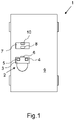
- the drawing shows, in the single Figure, a schematic representation of a motor vehicle in which sits a user who has put on a virtual reality headset.
- a motor vehicle 1 is shown in a highly schematic representation in Fig.1 .
- the virtual reality headset 3 further comprises a control device 4 for controlling the virtual reality headset 3, an inertial measurement unit 5 and a capture device 6. Both the inertial measurement unit 5 and the capture device 6 are attached to the virtual reality headset 3.
- a headrest 7 is also schematically indicated, to which a visual reference 8 is applied.
- the motor vehicle 1 is fixedly equipped with a vehicle localisation system 10 that can provide vehicle localisation data describing the pose and/or movement of the motor vehicle 10 in the outside world, i.e. with respect to a fixed world reference frame or coordinate system to the control device 4, for example via a wireless data connection.
- a procedure for operating the virtual reality headset 3 is explained below. While a virtual environment is displayed by means of the virtual reality headset 3, the inertial measurement unit 5 continuously determines an instantaneous orientation of the virtual reality headset 3.
- the inertial measurement unit 5 does not measure the orientation of the virtual reality headset relative to the car but relative to the outside fixed world reference frame, its data can be combined with the vehicle localisation data provided by the vehicle localisation system 10. This enables determination of the orientation of the instantaneous orientation of the virtual reality headset 3 with respect to the motor vehicle 1, in particular its vehicle interior 9, i.e. a vehicle coordinate system moving with the motor vehicle 1.
- Corresponding data characterising at least the respective instantaneous orientation, and possibly a position, of the virtual reality headset 3 are transmitted to the control device 4. Based on these data, the control device 4 simulates a virtual perspective of the person 2 on the virtual environment currently displayed by the virtual reality headset 3.
- the virtual environment can, for example, be a scene in a computer game.
- the virtual perspective displayed within the computer game changes accordingly.
- the person 2 also moves his head to the left or right accordingly.
- turning movements of person 2 with his head are thus converted more or less one-to-one within the displayed virtual environment.
- translational movements of the head of person 2 can also be implemented accordingly.
- the problem may arise that a so-called drift occurs over time if the data obtained by means of, for example, acceleration sensors, angular velocity sensor, and/or other sensors of the inertial measurement unit 5 provide visibly slightly incorrect data when integrated, i.e. the actual head orientation of person 2 or the actual orientation of the virtual reality headset 3 is no longer reproduced exactly.
- a relative arrangement, in particular the pose, of the virtual reality headset 3 with respect to the vehicle interior 9 of motor vehicle 1 is determined at predetermined time intervals by means of the optical capture device 6 arranged on the virtual reality headset 3.
- the optical capture device 6 can therefore for its part determine the alignment or orientation of the virtual reality headset 3 and does so relative to the vehicle interior 9.
- the respectively determined orientations or poses of the virtual reality headset 3, which were determined by means of the inertial measurement unit 5 and by means of the capture device 6 are fused together, in particular by feeding them as input into an error-state extended Kalman filter provided as part of the control device 4. This provides as an output of the filter a corrected orientation or pose of the virtual reality headset 3 that is smoothly corrected for the drift of the inertial measurement unit 5.
- the alignment or arrangement of the virtual reality headset 3 determined by means of the optical capture device 6 is assumed to be the correct alignment.
- the virtual perspective on the virtual environment displayed by means of the virtual reality headset 3 is then adapted, i.e. simulated based on the corrected orientation or pose.
- the optical capture device 6 once again carries out its own procedure to determine the orientation or pose of the virtual reality headset 3 relative to the vehicle interior 9, so that based on the data thus obtained - so far as necessary - the previously described smooth correction of the drift of the inertial measurement unit 5 can be carried out again through fusion of the respective data.
- the fusion i.e.
- the optical capture device 6 may, for example, be configured to recognise the visual reference 8 on the headrest 7 and, based thereon, to determine the relative arrangement of the virtual reality headset 3 to the headrest 7 and thus also to the vehicle interior 9.
- the visual reference 8 can be a logo or a two-dimensional code, for example in the form of a so-called April tag or QR code.
- the visual reference 8 can also be, for example, one or more LEDs that are operated with a specific light pattern, so that the optical capture device 6 can detect this light pattern or the relevant LEDs particularly easily.
- the visual reference 8 is not some form of light source, it may be provided that the visual reference 8 is phosphorescent and/or backlit or illuminated. In this way, even in poor lighting conditions, the optical capture device 6 can easily recognise the visual reference 8 at all times.
- the capture device 6 is configured to recognise the headrest 7 itself and, based on this, to determine the relative arrangement of the virtual reality headset 3 to the headrest 7 and thus to the vehicle interior 9.
- an exact digital model of the headrest 7 can be provided, so that the optical capture device 6 can recognise the headrest 7 by a comparison with this digital model.
- a digital model valid for all vehicles or headrests is provided, in which certain typical headrest features such as certain edges or geometric properties are provided. It is also possible in this case that the optical capture device 6 can recognise the respective headrest 7 by means of a comparison with the digital model concerned and thus determine the alignment of the virtual reality headset 3 with respect to the headrest 7 and thus with respect to the vehicle interior 9.
- the capture device 6 can capture a series of images of a part of the vehicle interior 9, in several individual images of the series of images at least one feature of the vehicle interior 9 being detected, and a change of position of this feature on the individual images being determined, and, based thereon, the relative arrangement of the virtual reality headset 3 with respect to the vehicle interior 9 is determined.
- the feature can be, for example, a part of the headrest 7 or completely different components in the vehicle interior 9.
- This so-called frame-to-frame visual tracking also makes it possible to determine by means of the optical capture device 6 the exact alignment or arrangement of the virtual reality headset 3 with respect to the vehicle interior 9 at specified intervals, in order to - if necessary - carry out based on this data the said correction of the orientation or pose data provided by the inertial measurement unit 5. In this context, it may in particular be provided to disregard any objects located at more than a predetermined distance from the capture device 6.
- the headrest 7 is to be recognised by means of the optical capture device 6, this being, for example, at a maximum distance of 70 cm from the capture device 6 in the case of a vehicle occupant sitting on the rear seat, it can be specified that all objects which are more than 70 cm away from the capture device 6 are not to be taken into account at all. In this way can be ruled out, for example, that objects located outside motor vehicle 1 or other vehicle occupants not shown here are tracked or detected. In this way it can be ensured that the actual alignment of the virtual reality headset 3 can be determined in a particularly precise manner by means of the optical capture device 6. Alternatively or additionally, it is also possible, for example, to use a convolutional neural network to detect the said feature.
Landscapes
- Engineering & Computer Science (AREA)
- Chemical & Material Sciences (AREA)
- Combustion & Propulsion (AREA)
- Transportation (AREA)
- Mechanical Engineering (AREA)
- Theoretical Computer Science (AREA)
- General Engineering & Computer Science (AREA)
- General Physics & Mathematics (AREA)
- Physics & Mathematics (AREA)
- Human Computer Interaction (AREA)
- Computer Vision & Pattern Recognition (AREA)
- Position Input By Displaying (AREA)
- User Interface Of Digital Computer (AREA)
- Processing Or Creating Images (AREA)
- Instrument Panels (AREA)
- Image Analysis (AREA)
Claims (12)
- Procédé d'utilisation d'un casque de réalité virtuelle (3) dans un véhicule (1), dans lequel- des données de localisation du véhicule qui caractérisent au moins partiellement une posture et/ou un mouvement du véhicule (1) relativement à une trame de référence du monde fixe sont capturées et fournies,- une orientation instantanée du casque de réalité virtuelle (3) relativement à un intérieur de véhicule (9) du véhicule (1) est continuellement déterminée sur la base d'une mesure inertielle réalisée par une unité de mesure inertielle (5) agencée sur le casque de réalité virtuelle (3) et les données de localisation du véhicule et sur la base de celles-ci, une perspective virtuelle sur un environnement virtuel affiché au moyen du casque de réalité virtuelle (3) est simulée ;caractérisé en ce que- à des intervalles de temps prédéterminés, un suivi optique est réalisé au moyen d'un dispositif de capture optique (6) agencé sur le casque de réalité virtuelle (3) qui détermine un agencement du casque de réalité virtuelle (3) par rapport à l'intérieur (9) du véhicule (1) ;- après quoi au moins une orientation du casque de réalité virtuelle (3) relativement à l'intérieur du véhicule (9) est déterminée au moyen d'une fusion de l'orientation instantanée déterminée et du suivi optique, et sur la base de celle-ci, la perspective virtuelle sur l'environnement virtuel affiché au moyen du casque de réalité virtuelle (3) est simulée, dans lequel la fusion contre une dérive de l'unité de mesure inertielle dans le temps.
- Procédé selon la revendication 1,
caractérisé en ce que
un repère visuel (8) est agencé sur un composant du véhicule, en particulier sur un côté arrière de l'appui-tête (7), dans lequel le dispositif de capture (6) reconnaît le repère visuel (8) et sur la base de celui-ci, détermine l'agencement correspondant du casque de réalité virtuelle (3) par rapport au composant de véhicule et donc par rapport à l'intérieur du véhicule (9). - Procédé selon la revendication 2,
caractérisé en ce que
le repère visuel (8) utilisé est un logo ou un code en deux dimensions, en particulier une étiquette Avril ou un QR code, ou une source lumineuse actionnée avec un motif lumineux prédéterminé, en particulier au moins une LED. - Procédé selon la revendication 2 ou 3,
caractérisé en ce que
le repère visuel (8) est phosphorescent et/ou rétroéclairé ou éclairé. - Procédé selon l'une quelconque des revendications précédentes
caractérisé en ce que
le dispositif de capture (6) reconnaît lui-même un composant de véhicule prédéterminé et, sur la base de celui-ci, détermine l'agencement correspondant du casque de réalité virtuelle (3) par rapport au composant du véhicule et donc à l'intérieur du véhicule (9). - Procédé selon la revendication 5,
caractérisé en ce que
un modèle numérique du composant de véhicule est fourni, dans lequel le dispositif de capture (6) reconnaît le composant du véhicule par une comparaison avec le modèle numérique. - Procédé selon la revendication 6,
caractérisé en ce que
le modèle numérique est créé d'une manière spécifique au véhicule. - Procédé selon la revendication 6,
caractérisé en ce que
le modèle numérique est créé comme un modèle non-spécifique à un véhicule. - Procédé selon l'une quelconque des revendications précédentes,
caractérisé en ce que
une série d'images est capturée d'une partie de l'intérieur du véhicule (9), au moins une caractéristique de l'intérieur du véhicule (9) dans une pluralité d'images individuelles de la série d'images et un changement de position de cette caractéristique dans les images individuelles est détecté et sur la base de celui-ci, l'agencement correspondant du casque de réalité virtuelle (3) relativement à l'intérieur du véhicule (9) est déterminé. - Procédé selon la revendication 9,
caractérisé en ce que
des objets situés à plus d'une distance prédéterminée du dispositif de capture (6) ne sont pas pris en compte. - Procédé selon la revendication 9 ou 10,
caractérisé en ce que
un réseau neuronal convolutif est utilisé pour détecter le au moins une caractéristique. - Dispositif de commande (4) pour faire fonctionner un casque de réalité virtuelle (3) dans un véhicule (1) qui est configuré ainsi, sur la base de- une orientation instantanée, au moins continuellement déterminée, au moyen d'une unité de mesure inertielle (5) agencée sur le casque de réalité virtuelle (3) et de données de localisation de véhicule fournies qui caractérisent au moins partiellement une posture et/ou un mouvement du véhicule (1) par rapport à une trame de référence de monde fixe, du casque de réalité virtuelle (3), afin de simuler une perspective virtuelle sur un environnement virtuel affiché au moyen du casque de réalité virtuelle (3) ;caractérisé en ce que
le dispositif de commande (4) est configuré pour faire fonctionner un casque de réalité virtuelle (3) sur la base de- un agencement relatif du casque de réalité virtuelle (3) relativement à l'intérieur (9) du véhicule (1) déterminé à des intervalles de temps prédéterminés au moyen d'un dispositif de capture optique (6) agencé sur le casque de réalité virtuelle (3) pour réaliser un suivi optique ; et- au moins une orientation déterminée continuellement, par le biais d'une fusion de l'orientation instantanée déterminée avec l'agencement relatif déterminé, du casque de réalité virtuelle (3), afin de simuler la perspective virtuelle sur l'environnement virtuel affiché par le casque de réalité virtuelle (3), dans lequel la fusion contre une dérive de l'unité de mesure inertielle dans le temps.
Applications Claiming Priority (2)
| Application Number | Priority Date | Filing Date | Title |
|---|---|---|---|
| EP19205788 | 2019-10-29 | ||
| PCT/EP2020/076451 WO2021083584A1 (fr) | 2019-10-29 | 2020-09-22 | Procédé et dispositif de commande pour le fonctionnement d'un casque de réalité virtuelle dans un véhicule |
Publications (2)
| Publication Number | Publication Date |
|---|---|
| EP3990302A1 EP3990302A1 (fr) | 2022-05-04 |
| EP3990302B1 true EP3990302B1 (fr) | 2023-01-11 |
Family
ID=68387196
Family Applications (1)
| Application Number | Title | Priority Date | Filing Date |
|---|---|---|---|
| EP20772090.5A Active EP3990302B1 (fr) | 2019-10-29 | 2020-09-22 | Procédé et dispositif de commande pour le fonctionnement d'un casque de réalité virtuelle dans un véhicule |
Country Status (6)
| Country | Link |
|---|---|
| US (1) | US11609626B2 (fr) |
| EP (1) | EP3990302B1 (fr) |
| JP (1) | JP7209316B2 (fr) |
| KR (1) | KR102457608B1 (fr) |
| CN (1) | CN114286762B (fr) |
| WO (1) | WO2021083584A1 (fr) |
Families Citing this family (4)
| Publication number | Priority date | Publication date | Assignee | Title |
|---|---|---|---|---|
| CN114979615B (zh) * | 2022-05-11 | 2024-10-25 | 闪耀现实(无锡)科技有限公司 | 用于在头戴显示设备显示画面的方法、装置及电子设备 |
| JP2025520401A (ja) * | 2022-06-13 | 2025-07-03 | ビ-エイイ- システムズ パブリック リミテッド カンパニ- | 頭部追跡システム |
| CN115686205A (zh) * | 2022-10-19 | 2023-02-03 | 蔚来汽车科技(安徽)有限公司 | 交互方法、车机系统及包括其的车辆、存储介质 |
| CN117782114B (zh) * | 2024-02-28 | 2024-06-25 | 福瑞泰克智能系统有限公司 | 车辆定位校正方法、装置、计算机设备和存储介质 |
Family Cites Families (17)
| Publication number | Priority date | Publication date | Assignee | Title |
|---|---|---|---|---|
| US6474159B1 (en) | 2000-04-21 | 2002-11-05 | Intersense, Inc. | Motion-tracking |
| DE102013207063A1 (de) * | 2013-04-19 | 2014-10-23 | Bayerische Motoren Werke Aktiengesellschaft | Verfahren zum Auswählen einer Informationsquelle aus einer Mehrzahl von Informationsquellen zur Anzeige auf einer Anzeige einer Datenbrille |
| US9766075B2 (en) | 2014-05-02 | 2017-09-19 | Thales Visionix, Inc. | Registration for vehicular augmented reality using auto-harmonization |
| US9928544B1 (en) * | 2015-03-10 | 2018-03-27 | Amazon Technologies, Inc. | Vehicle component installation preview image generation |
| EP3158293B1 (fr) * | 2015-05-23 | 2019-01-23 | SZ DJI Technology Co., Ltd. | Fusion de capteurs à l'aide de capteurs inertiels et d'images |
| GB201516121D0 (en) * | 2015-09-11 | 2015-10-28 | Bae Systems Plc | Helmet tracker buffering compensation |
| DE102016104337A1 (de) | 2016-03-09 | 2017-09-14 | Vr Coaster Gmbh & Co. Kg | Positionsbestimmung und Ausrichtung eines Virtual Reality Headsets und Fahrgeschäft mit einem Virtual Reality Headset |
| US9459692B1 (en) | 2016-03-29 | 2016-10-04 | Ariadne's Thread (Usa), Inc. | Virtual reality headset with relative motion head tracker |
| US10043076B1 (en) * | 2016-08-29 | 2018-08-07 | PerceptIn, Inc. | Visual-inertial positional awareness for autonomous and non-autonomous tracking |
| US10503245B2 (en) | 2016-09-21 | 2019-12-10 | Apple Inc. | Relative intertial measurement system |
| US10580386B2 (en) * | 2017-04-21 | 2020-03-03 | Ford Global Technologies, Llc | In-vehicle projected reality motion correction |
| US10216265B1 (en) * | 2017-08-07 | 2019-02-26 | Rockwell Collins, Inc. | System and method for hybrid optical/inertial headtracking via numerically stable Kalman filter |
| DE102017222534B3 (de) | 2017-12-12 | 2019-06-13 | Volkswagen Aktiengesellschaft | Verfahren, computerlesbares Speichermedium mit Instruktionen, Vorrichtung und System zum Einmessen einer Augmented-Reality-Brille in einem Fahrzeug, für das Verfahren geeignetes Fahrzeug und für das Verfahren geeignete Augmented-Reality-Brille |
| DE102018203753A1 (de) * | 2018-03-13 | 2019-09-19 | Robert Bosch Gmbh | Verfahren und Vorrichtung zur robusten Lokalisierung eines Fahrzeugs |
| US10416755B1 (en) * | 2018-06-01 | 2019-09-17 | Finch Technologies Ltd. | Motion predictions of overlapping kinematic chains of a skeleton model used to control a computer system |
| JP7032295B2 (ja) * | 2018-12-26 | 2022-03-08 | 本田技研工業株式会社 | 車両制御システム、車両制御方法、およびプログラム |
| US10767997B1 (en) * | 2019-02-25 | 2020-09-08 | Qualcomm Incorporated | Systems and methods for providing immersive extended reality experiences on moving platforms |
-
2020
- 2020-09-22 KR KR1020227006249A patent/KR102457608B1/ko active Active
- 2020-09-22 EP EP20772090.5A patent/EP3990302B1/fr active Active
- 2020-09-22 US US17/637,606 patent/US11609626B2/en active Active
- 2020-09-22 CN CN202080059537.9A patent/CN114286762B/zh active Active
- 2020-09-22 WO PCT/EP2020/076451 patent/WO2021083584A1/fr not_active Ceased
- 2020-09-22 JP JP2022513198A patent/JP7209316B2/ja active Active
Also Published As
| Publication number | Publication date |
|---|---|
| KR20220034910A (ko) | 2022-03-18 |
| EP3990302A1 (fr) | 2022-05-04 |
| US11609626B2 (en) | 2023-03-21 |
| CN114286762A (zh) | 2022-04-05 |
| JP7209316B2 (ja) | 2023-01-20 |
| CN114286762B (zh) | 2023-03-24 |
| KR102457608B1 (ko) | 2022-10-21 |
| WO2021083584A1 (fr) | 2021-05-06 |
| US20220283633A1 (en) | 2022-09-08 |
| JP2022545125A (ja) | 2022-10-25 |
Similar Documents
| Publication | Publication Date | Title |
|---|---|---|
| EP3990302B1 (fr) | Procédé et dispositif de commande pour le fonctionnement d'un casque de réalité virtuelle dans un véhicule | |
| US11200655B2 (en) | Wearable visualization system and method | |
| CN110031975B (zh) | 在车辆中校准增强现实眼镜的方法和系统与增强现实眼镜 | |
| JP5055516B2 (ja) | 拡張現実を使用して装置の保守命令および動作命令を表示するシステムおよび方法 | |
| JP4739002B2 (ja) | 画像処理方法、画像処理装置 | |
| CN108697936A (zh) | 虚拟现实头戴设备的位置确定和定向以及具有虚拟现实头戴设备的游乐设施 | |
| CN107014378A (zh) | 一种视线跟踪瞄准操控系统及方法 | |
| CN108107592A (zh) | 虚拟现实系统的校准 | |
| US10573083B2 (en) | Non-transitory computer-readable storage medium, computer-implemented method, and virtual reality system | |
| US20260056606A1 (en) | Wearable system with controller localization using headset cameras and controller fiducials | |
| CN110310328A (zh) | 混合现实操作配准方法及装置 | |
| JP2000347128A (ja) | ヘッドマウントディスプレイ装置およびヘッドマウントディスプレイシステム | |
| KR101507014B1 (ko) | 운송장치 시뮬레이션 시스템 및 그 제어방법 | |
| Feld et al. | Dfki cabin simulator: A test platform for visual in-cabin monitoring functions | |
| CN106991699B (zh) | 控制方法及电子设备 | |
| JP2009036517A (ja) | ヘッドモーショントラッカ装置 | |
| Feld et al. | Dfki cabin simulator: A test platform for visual in-cabin monitoring functions | |
| KR101934546B1 (ko) | 가상 현실 기반의 라이드 시스템 | |
| US12434098B2 (en) | Method, apparatus, and program for controlling display | |
| Tonnis et al. | Visualization of spatial sensor data in the context of automotive environment perception systems | |
| JP7778351B2 (ja) | 画像処理装置、画像処理方法及びプログラム | |
| Otto et al. | Validation of AI-Based 3D Human Pose Estimation in a Cyber-Physical Environment | |
| JP6864333B2 (ja) | 顔向き検出システム及び顔向き検出装置 | |
| JP2021081333A (ja) | 興味推定システム | |
| JPWO2019058734A1 (ja) | 情報表示装置及び方法、並びにプログラム及び記録媒体 |
Legal Events
| Date | Code | Title | Description |
|---|---|---|---|
| STAA | Information on the status of an ep patent application or granted ep patent |
Free format text: STATUS: UNKNOWN |
|
| STAA | Information on the status of an ep patent application or granted ep patent |
Free format text: STATUS: THE INTERNATIONAL PUBLICATION HAS BEEN MADE |
|
| PUAI | Public reference made under article 153(3) epc to a published international application that has entered the european phase |
Free format text: ORIGINAL CODE: 0009012 |
|
| STAA | Information on the status of an ep patent application or granted ep patent |
Free format text: STATUS: REQUEST FOR EXAMINATION WAS MADE |
|
| 17P | Request for examination filed |
Effective date: 20220127 |
|
| AK | Designated contracting states |
Kind code of ref document: A1 Designated state(s): AL AT BE BG CH CY CZ DE DK EE ES FI FR GB GR HR HU IE IS IT LI LT LU LV MC MK MT NL NO PL PT RO RS SE SI SK SM TR |
|
| GRAP | Despatch of communication of intention to grant a patent |
Free format text: ORIGINAL CODE: EPIDOSNIGR1 |
|
| STAA | Information on the status of an ep patent application or granted ep patent |
Free format text: STATUS: GRANT OF PATENT IS INTENDED |
|
| INTG | Intention to grant announced |
Effective date: 20220728 |
|
| RIN1 | Information on inventor provided before grant (corrected) |
Inventor name: PROFENDINER, DANIEL Inventor name: NOBILI, SIMONA |
|
| GRAS | Grant fee paid |
Free format text: ORIGINAL CODE: EPIDOSNIGR3 |
|
| GRAA | (expected) grant |
Free format text: ORIGINAL CODE: 0009210 |
|
| STAA | Information on the status of an ep patent application or granted ep patent |
Free format text: STATUS: THE PATENT HAS BEEN GRANTED |
|
| DAV | Request for validation of the european patent (deleted) | ||
| DAX | Request for extension of the european patent (deleted) | ||
| AK | Designated contracting states |
Kind code of ref document: B1 Designated state(s): AL AT BE BG CH CY CZ DE DK EE ES FI FR GB GR HR HU IE IS IT LI LT LU LV MC MK MT NL NO PL PT RO RS SE SI SK SM TR |
|
| REG | Reference to a national code |
Ref country code: GB Ref legal event code: FG4D |
|
| REG | Reference to a national code |
Ref country code: CH Ref legal event code: EP |
|
| REG | Reference to a national code |
Ref country code: DE Ref legal event code: R096 Ref document number: 602020007570 Country of ref document: DE |
|
| REG | Reference to a national code |
Ref country code: IE Ref legal event code: FG4D |
|
| REG | Reference to a national code |
Ref country code: AT Ref legal event code: REF Ref document number: 1543222 Country of ref document: AT Kind code of ref document: T Effective date: 20230215 |
|
| REG | Reference to a national code |
Ref country code: LT Ref legal event code: MG9D |
|
| REG | Reference to a national code |
Ref country code: NL Ref legal event code: MP Effective date: 20230111 |
|
| REG | Reference to a national code |
Ref country code: AT Ref legal event code: MK05 Ref document number: 1543222 Country of ref document: AT Kind code of ref document: T Effective date: 20230111 |
|
| PG25 | Lapsed in a contracting state [announced via postgrant information from national office to epo] |
Ref country code: NL Free format text: LAPSE BECAUSE OF FAILURE TO SUBMIT A TRANSLATION OF THE DESCRIPTION OR TO PAY THE FEE WITHIN THE PRESCRIBED TIME-LIMIT Effective date: 20230111 |
|
| P01 | Opt-out of the competence of the unified patent court (upc) registered |
Effective date: 20230608 |
|
| PG25 | Lapsed in a contracting state [announced via postgrant information from national office to epo] |
Ref country code: RS Free format text: LAPSE BECAUSE OF FAILURE TO SUBMIT A TRANSLATION OF THE DESCRIPTION OR TO PAY THE FEE WITHIN THE PRESCRIBED TIME-LIMIT Effective date: 20230111 Ref country code: PT Free format text: LAPSE BECAUSE OF FAILURE TO SUBMIT A TRANSLATION OF THE DESCRIPTION OR TO PAY THE FEE WITHIN THE PRESCRIBED TIME-LIMIT Effective date: 20230511 Ref country code: NO Free format text: LAPSE BECAUSE OF FAILURE TO SUBMIT A TRANSLATION OF THE DESCRIPTION OR TO PAY THE FEE WITHIN THE PRESCRIBED TIME-LIMIT Effective date: 20230411 Ref country code: LV Free format text: LAPSE BECAUSE OF FAILURE TO SUBMIT A TRANSLATION OF THE DESCRIPTION OR TO PAY THE FEE WITHIN THE PRESCRIBED TIME-LIMIT Effective date: 20230111 Ref country code: LT Free format text: LAPSE BECAUSE OF FAILURE TO SUBMIT A TRANSLATION OF THE DESCRIPTION OR TO PAY THE FEE WITHIN THE PRESCRIBED TIME-LIMIT Effective date: 20230111 Ref country code: HR Free format text: LAPSE BECAUSE OF FAILURE TO SUBMIT A TRANSLATION OF THE DESCRIPTION OR TO PAY THE FEE WITHIN THE PRESCRIBED TIME-LIMIT Effective date: 20230111 Ref country code: ES Free format text: LAPSE BECAUSE OF FAILURE TO SUBMIT A TRANSLATION OF THE DESCRIPTION OR TO PAY THE FEE WITHIN THE PRESCRIBED TIME-LIMIT Effective date: 20230111 Ref country code: AT Free format text: LAPSE BECAUSE OF FAILURE TO SUBMIT A TRANSLATION OF THE DESCRIPTION OR TO PAY THE FEE WITHIN THE PRESCRIBED TIME-LIMIT Effective date: 20230111 |
|
| PG25 | Lapsed in a contracting state [announced via postgrant information from national office to epo] |
Ref country code: SE Free format text: LAPSE BECAUSE OF FAILURE TO SUBMIT A TRANSLATION OF THE DESCRIPTION OR TO PAY THE FEE WITHIN THE PRESCRIBED TIME-LIMIT Effective date: 20230111 Ref country code: PL Free format text: LAPSE BECAUSE OF FAILURE TO SUBMIT A TRANSLATION OF THE DESCRIPTION OR TO PAY THE FEE WITHIN THE PRESCRIBED TIME-LIMIT Effective date: 20230111 Ref country code: IS Free format text: LAPSE BECAUSE OF FAILURE TO SUBMIT A TRANSLATION OF THE DESCRIPTION OR TO PAY THE FEE WITHIN THE PRESCRIBED TIME-LIMIT Effective date: 20230511 Ref country code: GR Free format text: LAPSE BECAUSE OF FAILURE TO SUBMIT A TRANSLATION OF THE DESCRIPTION OR TO PAY THE FEE WITHIN THE PRESCRIBED TIME-LIMIT Effective date: 20230412 Ref country code: FI Free format text: LAPSE BECAUSE OF FAILURE TO SUBMIT A TRANSLATION OF THE DESCRIPTION OR TO PAY THE FEE WITHIN THE PRESCRIBED TIME-LIMIT Effective date: 20230111 |
|
| REG | Reference to a national code |
Ref country code: DE Ref legal event code: R097 Ref document number: 602020007570 Country of ref document: DE |
|
| PG25 | Lapsed in a contracting state [announced via postgrant information from national office to epo] |
Ref country code: SM Free format text: LAPSE BECAUSE OF FAILURE TO SUBMIT A TRANSLATION OF THE DESCRIPTION OR TO PAY THE FEE WITHIN THE PRESCRIBED TIME-LIMIT Effective date: 20230111 Ref country code: RO Free format text: LAPSE BECAUSE OF FAILURE TO SUBMIT A TRANSLATION OF THE DESCRIPTION OR TO PAY THE FEE WITHIN THE PRESCRIBED TIME-LIMIT Effective date: 20230111 Ref country code: EE Free format text: LAPSE BECAUSE OF FAILURE TO SUBMIT A TRANSLATION OF THE DESCRIPTION OR TO PAY THE FEE WITHIN THE PRESCRIBED TIME-LIMIT Effective date: 20230111 Ref country code: DK Free format text: LAPSE BECAUSE OF FAILURE TO SUBMIT A TRANSLATION OF THE DESCRIPTION OR TO PAY THE FEE WITHIN THE PRESCRIBED TIME-LIMIT Effective date: 20230111 Ref country code: CZ Free format text: LAPSE BECAUSE OF FAILURE TO SUBMIT A TRANSLATION OF THE DESCRIPTION OR TO PAY THE FEE WITHIN THE PRESCRIBED TIME-LIMIT Effective date: 20230111 |
|
| PLBE | No opposition filed within time limit |
Free format text: ORIGINAL CODE: 0009261 |
|
| STAA | Information on the status of an ep patent application or granted ep patent |
Free format text: STATUS: NO OPPOSITION FILED WITHIN TIME LIMIT |
|
| REG | Reference to a national code |
Ref country code: DE Ref legal event code: R079 Ref document number: 602020007570 Country of ref document: DE Free format text: PREVIOUS MAIN CLASS: B60K0037060000 Ipc: B60K0035100000 |
|
| PG25 | Lapsed in a contracting state [announced via postgrant information from national office to epo] |
Ref country code: SK Free format text: LAPSE BECAUSE OF FAILURE TO SUBMIT A TRANSLATION OF THE DESCRIPTION OR TO PAY THE FEE WITHIN THE PRESCRIBED TIME-LIMIT Effective date: 20230111 |
|
| 26N | No opposition filed |
Effective date: 20231012 |
|
| PG25 | Lapsed in a contracting state [announced via postgrant information from national office to epo] |
Ref country code: SI Free format text: LAPSE BECAUSE OF FAILURE TO SUBMIT A TRANSLATION OF THE DESCRIPTION OR TO PAY THE FEE WITHIN THE PRESCRIBED TIME-LIMIT Effective date: 20230111 |
|
| REG | Reference to a national code |
Ref country code: CH Ref legal event code: PL |
|
| PG25 | Lapsed in a contracting state [announced via postgrant information from national office to epo] |
Ref country code: LU Free format text: LAPSE BECAUSE OF NON-PAYMENT OF DUE FEES Effective date: 20230922 |
|
| REG | Reference to a national code |
Ref country code: BE Ref legal event code: MM Effective date: 20230930 |
|
| PG25 | Lapsed in a contracting state [announced via postgrant information from national office to epo] |
Ref country code: LU Free format text: LAPSE BECAUSE OF NON-PAYMENT OF DUE FEES Effective date: 20230922 Ref country code: IT Free format text: LAPSE BECAUSE OF FAILURE TO SUBMIT A TRANSLATION OF THE DESCRIPTION OR TO PAY THE FEE WITHIN THE PRESCRIBED TIME-LIMIT Effective date: 20230111 Ref country code: MC Free format text: LAPSE BECAUSE OF FAILURE TO SUBMIT A TRANSLATION OF THE DESCRIPTION OR TO PAY THE FEE WITHIN THE PRESCRIBED TIME-LIMIT Effective date: 20230111 |
|
| REG | Reference to a national code |
Ref country code: IE Ref legal event code: MM4A |
|
| PG25 | Lapsed in a contracting state [announced via postgrant information from national office to epo] |
Ref country code: IE Free format text: LAPSE BECAUSE OF NON-PAYMENT OF DUE FEES Effective date: 20230922 |
|
| PG25 | Lapsed in a contracting state [announced via postgrant information from national office to epo] |
Ref country code: CH Free format text: LAPSE BECAUSE OF NON-PAYMENT OF DUE FEES Effective date: 20230930 |
|
| PG25 | Lapsed in a contracting state [announced via postgrant information from national office to epo] |
Ref country code: IE Free format text: LAPSE BECAUSE OF NON-PAYMENT OF DUE FEES Effective date: 20230922 Ref country code: CH Free format text: LAPSE BECAUSE OF NON-PAYMENT OF DUE FEES Effective date: 20230930 |
|
| PG25 | Lapsed in a contracting state [announced via postgrant information from national office to epo] |
Ref country code: BE Free format text: LAPSE BECAUSE OF NON-PAYMENT OF DUE FEES Effective date: 20230930 |
|
| PG25 | Lapsed in a contracting state [announced via postgrant information from national office to epo] |
Ref country code: BG Free format text: LAPSE BECAUSE OF FAILURE TO SUBMIT A TRANSLATION OF THE DESCRIPTION OR TO PAY THE FEE WITHIN THE PRESCRIBED TIME-LIMIT Effective date: 20230111 |
|
| PG25 | Lapsed in a contracting state [announced via postgrant information from national office to epo] |
Ref country code: BG Free format text: LAPSE BECAUSE OF FAILURE TO SUBMIT A TRANSLATION OF THE DESCRIPTION OR TO PAY THE FEE WITHIN THE PRESCRIBED TIME-LIMIT Effective date: 20230111 |
|
| PG25 | Lapsed in a contracting state [announced via postgrant information from national office to epo] |
Ref country code: CY Free format text: LAPSE BECAUSE OF FAILURE TO SUBMIT A TRANSLATION OF THE DESCRIPTION OR TO PAY THE FEE WITHIN THE PRESCRIBED TIME-LIMIT; INVALID AB INITIO Effective date: 20200922 |
|
| PG25 | Lapsed in a contracting state [announced via postgrant information from national office to epo] |
Ref country code: HU Free format text: LAPSE BECAUSE OF FAILURE TO SUBMIT A TRANSLATION OF THE DESCRIPTION OR TO PAY THE FEE WITHIN THE PRESCRIBED TIME-LIMIT; INVALID AB INITIO Effective date: 20200922 |
|
| PG25 | Lapsed in a contracting state [announced via postgrant information from national office to epo] |
Ref country code: TR Free format text: LAPSE BECAUSE OF FAILURE TO SUBMIT A TRANSLATION OF THE DESCRIPTION OR TO PAY THE FEE WITHIN THE PRESCRIBED TIME-LIMIT Effective date: 20230111 |
|
| PGFP | Annual fee paid to national office [announced via postgrant information from national office to epo] |
Ref country code: DE Payment date: 20251128 Year of fee payment: 6 |
|
| REG | Reference to a national code |
Ref country code: DE Ref legal event code: R082 Ref document number: 602020007570 Country of ref document: DE Representative=s name: HOFSTETTER, SCHURACK & PARTNER - PATENT- UND R, DE |
|
| PGFP | Annual fee paid to national office [announced via postgrant information from national office to epo] |
Ref country code: GB Payment date: 20260325 Year of fee payment: 6 |
|
| PGFP | Annual fee paid to national office [announced via postgrant information from national office to epo] |
Ref country code: FR Payment date: 20260330 Year of fee payment: 6 |