EP3990727B1 - Dispositif de verrouillage destiné à un récipient ou un couvercle, en particulier de véhicules automobiles, et pouvant être actionné entre une position fermée et une position ouverte - Google Patents
Dispositif de verrouillage destiné à un récipient ou un couvercle, en particulier de véhicules automobiles, et pouvant être actionné entre une position fermée et une position ouverte Download PDFInfo
- Publication number
- EP3990727B1 EP3990727B1 EP20760431.5A EP20760431A EP3990727B1 EP 3990727 B1 EP3990727 B1 EP 3990727B1 EP 20760431 A EP20760431 A EP 20760431A EP 3990727 B1 EP3990727 B1 EP 3990727B1
- Authority
- EP
- European Patent Office
- Prior art keywords
- container
- cover
- lever
- locking device
- lid
- Prior art date
- Legal status (The legal status is an assumption and is not a legal conclusion. Google has not performed a legal analysis and makes no representation as to the accuracy of the status listed.)
- Active
Links
Images


Classifications
-
- E—FIXED CONSTRUCTIONS
- E05—LOCKS; KEYS; WINDOW OR DOOR FITTINGS; SAFES
- E05C—BOLTS OR FASTENING DEVICES FOR WINGS, SPECIALLY FOR DOORS OR WINDOWS
- E05C19/00—Other devices specially designed for securing wings, e.g. with suction cups
- E05C19/02—Automatic catches, i.e. released by pull or pressure on the wing
- E05C19/022—Released by pushing in the closing direction
-
- E—FIXED CONSTRUCTIONS
- E05—LOCKS; KEYS; WINDOW OR DOOR FITTINGS; SAFES
- E05B—LOCKS; ACCESSORIES THEREFOR; HANDCUFFS
- E05B77/00—Vehicle locks characterised by special functions or purposes
- E05B77/02—Vehicle locks characterised by special functions or purposes for accident situations
- E05B77/04—Preventing unwanted lock actuation, e.g. unlatching, at the moment of collision
- E05B77/06—Preventing unwanted lock actuation, e.g. unlatching, at the moment of collision by means of inertial forces
-
- E—FIXED CONSTRUCTIONS
- E05—LOCKS; KEYS; WINDOW OR DOOR FITTINGS; SAFES
- E05B—LOCKS; ACCESSORIES THEREFOR; HANDCUFFS
- E05B83/00—Vehicle locks specially adapted for particular types of wing or vehicle
- E05B83/28—Locks for glove compartments, console boxes, fuel inlet covers or the like
- E05B83/32—Locks for glove compartments, console boxes, fuel inlet covers or the like for console boxes, e.g. between passenger seats
Definitions
- the invention relates to a locking device for a container or lid that can be actuated relative to a housing part between a closed and open position, in particular for motor vehicles, with a link and a guide pin which engages in the link and is arranged on a pivoted lever.
- Such a locking mechanism is, for example, from EP 1 253 271 A2 known.
- the locking mechanism has a connecting link and a pin which interacts with the connecting link and which is released from the connecting link by overpressing in the locking direction beyond a locked position in the connecting link.
- a push-push locking mechanism used to keep the drawer closed to be in the form of an inertial locking mechanism.
- the pin engaging in the connecting link is arranged on a pivoting lever which has an additional weight which, in the event of an accident, exerts a moment on the lever which prevents the pin from being released from a heart curve of the connecting link.
- From the DE 10 2010 050 800 A1 also discloses a locking device with a push-push mechanism for a container or lid for motor vehicles that can be actuated between a closed and open position relative to a housing part.
- the locking device has a backdrop and engaging in the backdrop and with the container or lid associated guide pin, wherein the container or the lid is held against the force of a spring element in a latching position.
- the link is designed as a cam bolt which can be displaced perpendicularly to the opening movement of the container or the lid depending on the position of the guide pin in the link.
- An inertia-controlled locking bar is provided, which is transferred under the influence of external acceleration forces in the pivoting direction of the container or lid into a position blocking the movement of the curved bar.
- a storage compartment or pull-out compartment for motor vehicles which can be moved in the manner of a drawer by being pulled out of a basic position into a position of use and protrudes into the passenger compartment in the open position is known.
- a pivotable bolt is provided which, in the event of a rear-end collision, engages with the pull-out part which is in the home position and locks it.
- a locking device for locking a pivot body that is rotatably mounted about a pivot axis, e.g. B. storage compartments in motor vehicle doors, known, wherein the pivoting body is biased by an actuating spring.
- a connecting link control is attached to the pivoting body and engages a pin of a pivotally mounted locking lever.
- the locking lever is prevented from swiveling away and thus the swivel body from being opened undesirably in the event of a strong impulse, for example an impact, is prevented by an unlocking lock for fixing the locking lever in a locked position as soon as a strong impulse acts on the swivel body and at the same time on the locking device.
- the DE 94 12 661 U1 relates to a locking device for locking a pivoting body which is mounted so as to be rotatable about a pivoting axis and is pretensioned by an actuating spring, with a connecting link control which is engaged by a pin of a pivotally mounted locking lever.
- the U.S. 7,959,202 B2 relates to a vehicle pan with a mechanism to prevent opening, particularly in the event of a crash.
- the vehicle pan may include a rotating member integral with a cargo cover and rotatably coupled to the cargo cover to support the cargo cover.
- the invention is based on the object of specifying a locking device of the type mentioned at the outset, in which unintentional opening of the container or the lid when external acceleration forces act is reliably avoided by simple structural means.
- the locking device has a connecting link arranged, for example, on the container or lid, and a pin which engages in the connecting link and is arranged on a lever.
- the lever is pivotably mounted on the housing, for example, and can be moved into a position blocking its movement under the influence of external acceleration forces in the direction of actuation of the container or lid.
- the connecting link has an incline or ramp, through which the pin is raised under the influence of the acceleration forces occurring in an accident, for example in a frontal collision or also in the event of a side impact, in one embodiment in the direction of the vehicle vertical axis or in an alternative embodiment in the direction of the vehicle transverse axis is deflected to come into contact with a stop.
- the crash barrier according to the invention is characterized by an extremely simple structural design. In this case, only an incline or ramp can be integrated into the slotted guide for locking and unlocking the container or the lid, which is already present in the sliding or pivoting containers or lids. An additional inertia locking mechanism, eccentrically arranged additional weights or additional inertia-controlled locking bolts or even movably mounted weights are not required.
- the crash barrier according to the invention is activated solely by the acceleration force exerted on the container or lid.
- the triggering path of the container or the lid can be used to move it from the closed to the open position to lift or deflect the lever by a few angular degrees and bring it into contact with the stop so that the storage compartment or container remains closed .
- the pin is guided in the connecting link in order to move the container or lid from the closed to the open position.
- the lever experiences a movement component in the direction of one of the vehicle axles by means of the incline or ramp of the link guide in order to come into an operative position with a stop and to bring the container or lid into a locking position. This ensures that the objects stored in a container inside the vehicle do not fly around and injure vehicle occupants as a result of a crash. The container remains closed even in the event of a crash.
- the connecting link can be arranged with a slope on the container or lid and the lever can be pivoted on the housing.
- the reverse arrangement is also conceivable, with a link with a bevel on the housing and the lever with its pivot axis on the container or lid.
- the connecting link with a slope or ramp can extend on a side wall of the container or lid in its displacement direction, with the lever experiencing a moment in the direction of the vertical axis of the vehicle under the influence of the external acceleration forces, which transfers the lever into the contact position with the stop.
- the connecting link extends with a slope on or in the bottom of the container or lid in its direction of displacement, in which case the lever then experiences a moment in the transverse axis of the vehicle in the event of a vehicle impact and, during its lateral deflection movement, brings it into contact with the stop.
- the stop and the lever have latching and counter-latching means that interact with one another in the blocking position, so that it is ensured that in the event of a crash, the storage compartment will not open under any circumstances. after one In the event of a crash, the storage compartment can only be opened by overcoming the locking connection and moving the lid.
- the locking device it is of course also possible for the locking device to be used in a so-called push-push mechanism, with the container or lid being held in a latching position, for example a heart-shaped curve, against the force of a spring element.
- a latching position for example a heart-shaped curve
- the triggering path as part of the opening movement is used to deflect the lever by a few angular degrees in the event of a crash, so that the lever reaches the contact position without the storage compartment or the cover opening further.
- the storage compartment shown in the figures is intended, for example, for the center console of a motor vehicle.
- storage compartments which are pivotably arranged in the motor vehicle doors are also conceivable.
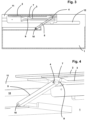
- the storage compartment has a housing 1 that can be inserted into a receptacle in the motor vehicle and that can be closed with a cover 2 .
- the lid 2 can be moved from a closing to an opening movement and vice versa.
- a connecting link 3 is provided on both sides of the cover 2 on its side walls, into which a pin 4 arranged on a lever 5 engages.
- the lever 5 is mounted on an axis of rotation 10 on the housing side.
- the connecting link 3 is used to fix the cover 2 in its open position.
- the guide tracks 12 on each side of the housing 1 have a contour in order to convert the cover 2 in the open position of the compartment in a space-saving manner.
- the cover 2 is briefly pushed in against the force of the spring (not shown) in the direction of the open position, which is also referred to as overpressing.
- the pin 4 disengages from the locking recess 14 of the heart curve 8, so that the open position is unlocked and the cover 2 returns to its closed position according to spring force Figures 1 and 2 transforms.
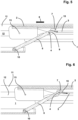
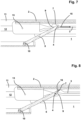
- the pin 4 slides along the backdrop 3 over a ramp 9 or slope in the position as in the figures 4 and 5 is shown.
- the pin 4 slides in the connecting link 3 until, in the open position, the pin 4 engages behind the locking recess 14 of the heart curve 8 and holds the cover 2 in the open position.
- This normal or slow opening speed of the lid 2 is in the Figures 4 to 7 shown.
- the cover 2 remains in its closed position with the storage compartment closed. If the deceleration of the vehicle, for example in the event of a rear-end collision, is so high, the cover 2 could move into the open position, so that the storage compartment Objects could fly around inside the vehicle and injure occupants.
- a stop 7 is provided on the cover 2 in the exemplary embodiment chosen here, against which the lever 5, which is pivotably mounted on the housing 1, comes into abutment position due to the influence of external acceleration forces.
- the pin 4 is accelerated over the ramp 9 so that, as indicated by the arrow 16, it strikes the stop 7, as a result of which an opening movement of the cover 2 is blocked and the cover 2 is in a blocking position.
- the spring travel specified by the push-push mechanism the spring travel reserve available in normal operation when the cover 2 is pushed over to unlock it, can be used to move the lever 5 into the blocking position of the cover 2 without the closed storage compartment opens further or fully.
- the end of the lever 5 that comes into the operative position and the stop 7 on the cover 2 are designed as interacting locking and counter-locking means, so that it is also ensured that the cover remains in its blocking position. If the vehicle occupant then moves the cover 2 into the closed position, the latching and counter-latching means on the lever 5 and the stop 7 are disengaged, so that the storage compartment can be operated normally again.
- connecting link 3 on the stationary housing, while levers 5 with pins 4 are arranged pivotably on the cover 2 or container.
Landscapes
- Engineering & Computer Science (AREA)
- Mechanical Engineering (AREA)
- Vehicle Step Arrangements And Article Storage (AREA)
- Lock And Its Accessories (AREA)
Claims (5)
- Dispositif de verrouillage pour un récipient ou un couvercle (2), notamment de véhicules automobiles, pouvant être actionné entre une position ouverte et fermée par rapport à une partie de boîtier (1), partie de boîtier (1) et récipient ou couvercle (2), le dispositif de verrouillage présentant une coulisse (3) ainsi qu'un tenon de guidage (4) s'engageant dans la coulisse (3), qui est agencé sur un levier (5) monté de manière pivotante, la coulisse (3) présentant un biseau (9) au moyen duquel le tenon (4) glisse, sous l'effet de forces d'accélération extérieures, en direction (16) d'une butée (7) agencée sur le récipient ou couvercle (2), afin d'amener le levier (5) dans une position bloquant le mouvement du récipient ou couvercle (2), caractérisé en ce que la butée (7) et le levier (5) présentent des moyens d'encliquetage et de contre-encliquetage coopérant entre eux en position de blocage.
- Dispositif de verrouillage, partie de boîtier (1) et récipient ou couvercle (2) selon la revendication 1, caractérisés en ce que la coulisse (3) avec biseau (9) est agencée sur le récipient ou couvercle (12) et le levier (5) est monté de manière pivotante sur le boîtier (1) ou inversement.
- Dispositif de verrouillage, partie de boîtier (1) et récipient ou couvercle (2) selon la revendication 1 ou 2, caractérisés en ce que la coulisse (3) avec biseau (9) s'étend sur une paroi latérale (11) du récipient ou couvercle (2) dans sa direction de déplacement (6), le levier (5) subissant, sous l'effet des forces d'accélération extérieures, un moment en direction de l'axe vertical (Z) du véhicule, qui transfère le levier (5) en position d'appui avec la butée (7).
- Dispositif de verrouillage, partie de boîtier (1) et récipient ou couvercle (2) selon la revendication 1 ou 2, caractérisés en ce que la coulisse (3) avec biseau (9) s'étend au fond du récipient ou couvercle (2) dans sa direction de déplacement (6) ou direction de pivotement, le levier (5) subissant, sous l'effet des forces d'accélération extérieures, un moment en direction de l'axe transversal (Y) du véhicule ou de l'axe longitudinal (X) du véhicule, qui transfère le levier (5) en position d'appui avec la butée (7).
- Dispositif de verrouillage, partie de boîtier (1) et récipient ou couvercle (2) selon l'une quelconque des revendications précédentes, caractérisés en ce qu'un mécanisme push-push pour le récipient ou couvercle (2) pouvant être actionné entre la position ouverte et fermée par rapport au boîtier (1) est prévu, le récipient ou couvercle (2) étant maintenu dans une position d'encliquetage contre la force d'un élément de ressort.
Applications Claiming Priority (1)
| Application Number | Priority Date | Filing Date | Title |
|---|---|---|---|
| PCT/EP2020/073171 WO2022037769A1 (fr) | 2020-08-19 | 2020-08-19 | Dispositif de verrouillage destiné à un récipient ou un couvercle, en particulier de véhicules automobiles, et pouvant être actionné entre une position fermée et une position ouverte |
Publications (2)
| Publication Number | Publication Date |
|---|---|
| EP3990727A1 EP3990727A1 (fr) | 2022-05-04 |
| EP3990727B1 true EP3990727B1 (fr) | 2023-05-03 |
Family
ID=72178523
Family Applications (1)
| Application Number | Title | Priority Date | Filing Date |
|---|---|---|---|
| EP20760431.5A Active EP3990727B1 (fr) | 2020-08-19 | 2020-08-19 | Dispositif de verrouillage destiné à un récipient ou un couvercle, en particulier de véhicules automobiles, et pouvant être actionné entre une position fermée et une position ouverte |
Country Status (5)
| Country | Link |
|---|---|
| US (1) | US12385292B2 (fr) |
| EP (1) | EP3990727B1 (fr) |
| CN (1) | CN115956155A (fr) |
| MX (1) | MX2023001922A (fr) |
| WO (1) | WO2022037769A1 (fr) |
Families Citing this family (1)
| Publication number | Priority date | Publication date | Assignee | Title |
|---|---|---|---|---|
| CN117627475B (zh) * | 2023-12-28 | 2026-04-21 | 东实李尔汽车座椅有限公司技术中心 | 一种盖板解锁装置 |
Citations (1)
| Publication number | Priority date | Publication date | Assignee | Title |
|---|---|---|---|---|
| US7959202B2 (en) * | 2008-05-07 | 2011-06-14 | Kia Motors Corporation | Vehicle tray having an open-prevention mechanism |
Family Cites Families (24)
| Publication number | Priority date | Publication date | Assignee | Title |
|---|---|---|---|---|
| DE9412661U1 (de) * | 1994-08-05 | 1994-10-06 | Sidler GmbH & Co, 72072 Tübingen | Verriegelungsvorrichtung |
| DE4427769A1 (de) | 1994-08-05 | 1996-02-08 | Winfried H Kasper | Anschlußdose |
| DE4427768C1 (de) * | 1994-08-05 | 1995-11-09 | Sidler Gmbh & Co | Verriegelungsvorrichtung |
| JPH08184237A (ja) * | 1994-12-28 | 1996-07-16 | Nifco Inc | 回動蓋のロック機構 |
| DE19835364C2 (de) | 1998-08-05 | 2000-06-08 | Fischer Artur Werke Gmbh | Vorrichtung zum Einbau in einem Kraftwagen mit einem Ausziehteil |
| JP4462768B2 (ja) * | 2001-01-19 | 2010-05-12 | 株式会社ニフコ | 安全機能付ロック装置及び乗物用収納装置 |
| DE10120435A1 (de) | 2001-04-26 | 2002-10-31 | Fischer Artur Werke Gmbh | Push-Push-Verriegelungsmechanik |
| US7303216B2 (en) * | 2005-02-22 | 2007-12-04 | Illinois Tool Works Inc. | Latch assembly |
| US7793995B2 (en) * | 2006-07-27 | 2010-09-14 | Illinois Tool Works Inc. | Push/push latch |
| JP4980042B2 (ja) | 2006-12-21 | 2012-07-18 | カルソニックカンセイ株式会社 | 車両用収納ボックスの蓋体ロック構造 |
| KR100921299B1 (ko) * | 2008-06-30 | 2009-10-09 | 현대자동차주식회사 | 트레이 열림 방지장치 |
| JP5336156B2 (ja) * | 2008-11-19 | 2013-11-06 | 株式会社ニフコ | 移動体のロック機構 |
| DE102009058988A1 (de) * | 2009-12-18 | 2011-06-22 | Dr. Ing. h.c. F. Porsche Aktiengesellschaft, 70435 | Kraftfahrzeug |
| DE202010006291U1 (de) | 2010-04-30 | 2011-09-23 | Minda Ktsn Plastic Solutions Gmbh & Co.Kg | Verriegelungseinrichtung |
| DE102010050800A1 (de) | 2010-11-09 | 2012-05-10 | Audi Ag | Verriegelungseinrichtung mit einer Push-Push-Mechanik für einen zwischen einer Schließ- und Offenstellung betätigbaren Behälter oder Deckel, insbesondere von Kraftfahrzeugen |
| DE112012002767T5 (de) * | 2011-08-09 | 2014-04-17 | Illinois Tool Works Inc. | Druck/Druck-Verriegelung |
| JP5785133B2 (ja) * | 2012-06-04 | 2015-09-24 | 本田技研工業株式会社 | 安全装置及び安全装置を使用したリッド付きケース |
| WO2015022106A1 (fr) * | 2013-08-14 | 2015-02-19 | Dr. Schneider Kunststoffwerke Gmbh | Dispositif pourvu d'un mécanisme « push-push » |
| WO2019010086A1 (fr) * | 2017-07-07 | 2019-01-10 | Shanghai Yanfeng Jinqiao Automotive Trim Systems Co. Ltd. | Composant d'intérieur de véhicule |
| CN207523514U (zh) * | 2017-11-08 | 2018-06-22 | 福特环球技术公司 | 用于车辆的收纳盒 |
| CN207737210U (zh) * | 2017-12-19 | 2018-08-17 | 宁波东昊汽车部件有限公司 | 一种汽车储物盒的抗滥用力机构 |
| US10696204B2 (en) * | 2018-10-31 | 2020-06-30 | GM Global Technology Operations LLC | Inertial latch |
| US11885171B2 (en) * | 2018-12-04 | 2024-01-30 | Shanghai Yanfeng Jinqiao Automotive Trim Systems Co. Ltd. | Vehicle interior component |
| US20200408005A1 (en) * | 2019-06-27 | 2020-12-31 | Ford Global Technologies, Llc | Bidirectional inertia latch for vehicle interior components |
-
2020
- 2020-08-19 MX MX2023001922A patent/MX2023001922A/es unknown
- 2020-08-19 EP EP20760431.5A patent/EP3990727B1/fr active Active
- 2020-08-19 US US18/007,385 patent/US12385292B2/en active Active
- 2020-08-19 CN CN202080103172.5A patent/CN115956155A/zh active Pending
- 2020-08-19 WO PCT/EP2020/073171 patent/WO2022037769A1/fr not_active Ceased
Patent Citations (1)
| Publication number | Priority date | Publication date | Assignee | Title |
|---|---|---|---|---|
| US7959202B2 (en) * | 2008-05-07 | 2011-06-14 | Kia Motors Corporation | Vehicle tray having an open-prevention mechanism |
Also Published As
| Publication number | Publication date |
|---|---|
| CN115956155A (zh) | 2023-04-11 |
| MX2023001922A (es) | 2023-06-01 |
| WO2022037769A1 (fr) | 2022-02-24 |
| US12385292B2 (en) | 2025-08-12 |
| EP3990727A1 (fr) | 2022-05-04 |
| US20230279701A1 (en) | 2023-09-07 |
Similar Documents
| Publication | Publication Date | Title |
|---|---|---|
| DE19835364C2 (de) | Vorrichtung zum Einbau in einem Kraftwagen mit einem Ausziehteil | |
| EP1926633B1 (fr) | Compartiment de rangement pour un vehicule automobile | |
| DE4130847C2 (de) | Verschlußkappe zum Verschließen eines Ablagefaches im Innenraum eines Kraftfahrzeuges | |
| DE102008006980A1 (de) | Fahrzeugsitzeinrichtung | |
| DE102010050800A1 (de) | Verriegelungseinrichtung mit einer Push-Push-Mechanik für einen zwischen einer Schließ- und Offenstellung betätigbaren Behälter oder Deckel, insbesondere von Kraftfahrzeugen | |
| EP1786649B1 (fr) | Element de guidage de ceinture pour un systeme de securite pour enfants | |
| DE102016220430A1 (de) | Trägheitssperrvorrichtung für eine Lösekabelanordnung | |
| DE102021131967A1 (de) | Sicherheitsbaugruppe zum Verhindern des Öffnens eines Fahrzeugschlosses bei vorgegebenen Fahrzeugzuständen | |
| DE102015114788A1 (de) | Behältnis mit einer Sicherheitsverriegelungsmechanik für ein Fahrzeug | |
| EP3990727B1 (fr) | Dispositif de verrouillage destiné à un récipient ou un couvercle, en particulier de véhicules automobiles, et pouvant être actionné entre une position fermée et une position ouverte | |
| DE10009291B4 (de) | Armlehne mit Staufach und verriegelbarem Deckel | |
| EP1660743A1 (fr) | Dispositif de verrouillage de securite destine a un contenant dans un vehicule | |
| EP3862269B1 (fr) | Compartiment de rangement pour un avion, ainsi qu'avion pourvu du compartiment de rangement | |
| DE102005027379B4 (de) | Verriegelungseinrichtung für einen Deckel an einem Ablagefach in einem Kraftfahrzeug | |
| EP2129550B1 (fr) | Volet de chargement par le coffre pour un siège de véhicule à moteur | |
| DE102007031591A1 (de) | Laderaumbodenanordnung | |
| EP1509663A1 (fr) | Dispositif de blocage securise pour recipient dans un vehicule | |
| DE102010023731A1 (de) | Sperreinrichtung für ein in einer Fahrzeugtüre eines Kraftfahrzeugs schwenkbar angeordneten Bauteils | |
| EP2072717A1 (fr) | Unité de poignée à palette, en particulier pour un compartiment de dépôt/coffre de rangement d'un véhicule automobile | |
| DE102023104395B4 (de) | Verriegelungsvorrichtung für einen gegenüber einem Gehäuseteil, insbesondere von Kraftfahrzeugen, zwischen einer Offen- und Schließstellung betätigbaren Deckel sowie Verfahren zum Ver- und Entriegeln eines einen Gehäuseteil verschließenden Deckels | |
| DE102010021050B4 (de) | Crashsicherung für ein Kfz-Bauteil | |
| WO2017036452A1 (fr) | Serrure de porte de véhicule automobile | |
| DE102010008900B4 (de) | Sicherheitsverriegelung für ein zwischen einer geschlossenen und einer geöffneten Stellung schwenkbares Funktionselement in einem Kraftfahrzeug | |
| DE102018107239B4 (de) | Ablagefach für ein kraftfahrzeug | |
| EP3266964B1 (fr) | Système destiné à empêcher une ouverture accidentelle d'une porte ou d'un clapet de véhicule et véhicule équipé d'un tel système |
Legal Events
| Date | Code | Title | Description |
|---|---|---|---|
| STAA | Information on the status of an ep patent application or granted ep patent |
Free format text: STATUS: UNKNOWN |
|
| STAA | Information on the status of an ep patent application or granted ep patent |
Free format text: STATUS: THE INTERNATIONAL PUBLICATION HAS BEEN MADE |
|
| PUAI | Public reference made under article 153(3) epc to a published international application that has entered the european phase |
Free format text: ORIGINAL CODE: 0009012 |
|
| STAA | Information on the status of an ep patent application or granted ep patent |
Free format text: STATUS: EXAMINATION IS IN PROGRESS |
|
| 17P | Request for examination filed |
Effective date: 20220127 |
|
| AK | Designated contracting states |
Kind code of ref document: A1 Designated state(s): AL AT BE BG CH CY CZ DE DK EE ES FI FR GB GR HR HU IE IS IT LI LT LU LV MC MK MT NL NO PL PT RO RS SE SI SK SM TR |
|
| GRAP | Despatch of communication of intention to grant a patent |
Free format text: ORIGINAL CODE: EPIDOSNIGR1 |
|
| STAA | Information on the status of an ep patent application or granted ep patent |
Free format text: STATUS: GRANT OF PATENT IS INTENDED |
|
| DAV | Request for validation of the european patent (deleted) | ||
| DAX | Request for extension of the european patent (deleted) | ||
| INTG | Intention to grant announced |
Effective date: 20230120 |
|
| GRAS | Grant fee paid |
Free format text: ORIGINAL CODE: EPIDOSNIGR3 |
|
| GRAA | (expected) grant |
Free format text: ORIGINAL CODE: 0009210 |
|
| STAA | Information on the status of an ep patent application or granted ep patent |
Free format text: STATUS: THE PATENT HAS BEEN GRANTED |
|
| AK | Designated contracting states |
Kind code of ref document: B1 Designated state(s): AL AT BE BG CH CY CZ DE DK EE ES FI FR GB GR HR HU IE IS IT LI LT LU LV MC MK MT NL NO PL PT RO RS SE SI SK SM TR |
|
| REG | Reference to a national code |
Ref country code: GB Ref legal event code: FG4D Free format text: NOT ENGLISH |
|
| REG | Reference to a national code |
Ref country code: DE Ref legal event code: R096 Ref document number: 502020003196 Country of ref document: DE |
|
| REG | Reference to a national code |
Ref country code: AT Ref legal event code: REF Ref document number: 1564720 Country of ref document: AT Kind code of ref document: T Effective date: 20230515 Ref country code: CH Ref legal event code: EP |
|
| REG | Reference to a national code |
Ref country code: IE Ref legal event code: FG4D Free format text: LANGUAGE OF EP DOCUMENT: GERMAN |
|
| P01 | Opt-out of the competence of the unified patent court (upc) registered |
Effective date: 20230530 |
|
| REG | Reference to a national code |
Ref country code: LT Ref legal event code: MG9D |
|
| REG | Reference to a national code |
Ref country code: NL Ref legal event code: MP Effective date: 20230503 |
|
| PG25 | Lapsed in a contracting state [announced via postgrant information from national office to epo] |
Ref country code: SE Free format text: LAPSE BECAUSE OF FAILURE TO SUBMIT A TRANSLATION OF THE DESCRIPTION OR TO PAY THE FEE WITHIN THE PRESCRIBED TIME-LIMIT Effective date: 20230503 Ref country code: PT Free format text: LAPSE BECAUSE OF FAILURE TO SUBMIT A TRANSLATION OF THE DESCRIPTION OR TO PAY THE FEE WITHIN THE PRESCRIBED TIME-LIMIT Effective date: 20230904 Ref country code: NO Free format text: LAPSE BECAUSE OF FAILURE TO SUBMIT A TRANSLATION OF THE DESCRIPTION OR TO PAY THE FEE WITHIN THE PRESCRIBED TIME-LIMIT Effective date: 20230803 Ref country code: NL Free format text: LAPSE BECAUSE OF FAILURE TO SUBMIT A TRANSLATION OF THE DESCRIPTION OR TO PAY THE FEE WITHIN THE PRESCRIBED TIME-LIMIT Effective date: 20230503 Ref country code: ES Free format text: LAPSE BECAUSE OF FAILURE TO SUBMIT A TRANSLATION OF THE DESCRIPTION OR TO PAY THE FEE WITHIN THE PRESCRIBED TIME-LIMIT Effective date: 20230503 |
|
| PG25 | Lapsed in a contracting state [announced via postgrant information from national office to epo] |
Ref country code: RS Free format text: LAPSE BECAUSE OF FAILURE TO SUBMIT A TRANSLATION OF THE DESCRIPTION OR TO PAY THE FEE WITHIN THE PRESCRIBED TIME-LIMIT Effective date: 20230503 Ref country code: PL Free format text: LAPSE BECAUSE OF FAILURE TO SUBMIT A TRANSLATION OF THE DESCRIPTION OR TO PAY THE FEE WITHIN THE PRESCRIBED TIME-LIMIT Effective date: 20230503 Ref country code: LV Free format text: LAPSE BECAUSE OF FAILURE TO SUBMIT A TRANSLATION OF THE DESCRIPTION OR TO PAY THE FEE WITHIN THE PRESCRIBED TIME-LIMIT Effective date: 20230503 Ref country code: LT Free format text: LAPSE BECAUSE OF FAILURE TO SUBMIT A TRANSLATION OF THE DESCRIPTION OR TO PAY THE FEE WITHIN THE PRESCRIBED TIME-LIMIT Effective date: 20230503 Ref country code: IS Free format text: LAPSE BECAUSE OF FAILURE TO SUBMIT A TRANSLATION OF THE DESCRIPTION OR TO PAY THE FEE WITHIN THE PRESCRIBED TIME-LIMIT Effective date: 20230903 Ref country code: HR Free format text: LAPSE BECAUSE OF FAILURE TO SUBMIT A TRANSLATION OF THE DESCRIPTION OR TO PAY THE FEE WITHIN THE PRESCRIBED TIME-LIMIT Effective date: 20230503 Ref country code: GR Free format text: LAPSE BECAUSE OF FAILURE TO SUBMIT A TRANSLATION OF THE DESCRIPTION OR TO PAY THE FEE WITHIN THE PRESCRIBED TIME-LIMIT Effective date: 20230804 |
|
| PG25 | Lapsed in a contracting state [announced via postgrant information from national office to epo] |
Ref country code: FI Free format text: LAPSE BECAUSE OF FAILURE TO SUBMIT A TRANSLATION OF THE DESCRIPTION OR TO PAY THE FEE WITHIN THE PRESCRIBED TIME-LIMIT Effective date: 20230503 |
|
| PG25 | Lapsed in a contracting state [announced via postgrant information from national office to epo] |
Ref country code: SK Free format text: LAPSE BECAUSE OF FAILURE TO SUBMIT A TRANSLATION OF THE DESCRIPTION OR TO PAY THE FEE WITHIN THE PRESCRIBED TIME-LIMIT Effective date: 20230503 |
|
| PG25 | Lapsed in a contracting state [announced via postgrant information from national office to epo] |
Ref country code: SM Free format text: LAPSE BECAUSE OF FAILURE TO SUBMIT A TRANSLATION OF THE DESCRIPTION OR TO PAY THE FEE WITHIN THE PRESCRIBED TIME-LIMIT Effective date: 20230503 Ref country code: SK Free format text: LAPSE BECAUSE OF FAILURE TO SUBMIT A TRANSLATION OF THE DESCRIPTION OR TO PAY THE FEE WITHIN THE PRESCRIBED TIME-LIMIT Effective date: 20230503 Ref country code: RO Free format text: LAPSE BECAUSE OF FAILURE TO SUBMIT A TRANSLATION OF THE DESCRIPTION OR TO PAY THE FEE WITHIN THE PRESCRIBED TIME-LIMIT Effective date: 20230503 Ref country code: EE Free format text: LAPSE BECAUSE OF FAILURE TO SUBMIT A TRANSLATION OF THE DESCRIPTION OR TO PAY THE FEE WITHIN THE PRESCRIBED TIME-LIMIT Effective date: 20230503 Ref country code: DK Free format text: LAPSE BECAUSE OF FAILURE TO SUBMIT A TRANSLATION OF THE DESCRIPTION OR TO PAY THE FEE WITHIN THE PRESCRIBED TIME-LIMIT Effective date: 20230503 Ref country code: CZ Free format text: LAPSE BECAUSE OF FAILURE TO SUBMIT A TRANSLATION OF THE DESCRIPTION OR TO PAY THE FEE WITHIN THE PRESCRIBED TIME-LIMIT Effective date: 20230503 |
|
| REG | Reference to a national code |
Ref country code: DE Ref legal event code: R097 Ref document number: 502020003196 Country of ref document: DE |
|
| PLBE | No opposition filed within time limit |
Free format text: ORIGINAL CODE: 0009261 |
|
| STAA | Information on the status of an ep patent application or granted ep patent |
Free format text: STATUS: NO OPPOSITION FILED WITHIN TIME LIMIT |
|
| PG25 | Lapsed in a contracting state [announced via postgrant information from national office to epo] |
Ref country code: MC Free format text: LAPSE BECAUSE OF FAILURE TO SUBMIT A TRANSLATION OF THE DESCRIPTION OR TO PAY THE FEE WITHIN THE PRESCRIBED TIME-LIMIT Effective date: 20230503 |
|
| REG | Reference to a national code |
Ref country code: CH Ref legal event code: PL |
|
| PG25 | Lapsed in a contracting state [announced via postgrant information from national office to epo] |
Ref country code: MC Free format text: LAPSE BECAUSE OF FAILURE TO SUBMIT A TRANSLATION OF THE DESCRIPTION OR TO PAY THE FEE WITHIN THE PRESCRIBED TIME-LIMIT Effective date: 20230503 |
|
| 26N | No opposition filed |
Effective date: 20240206 |
|
| PG25 | Lapsed in a contracting state [announced via postgrant information from national office to epo] |
Ref country code: LU Free format text: LAPSE BECAUSE OF NON-PAYMENT OF DUE FEES Effective date: 20230819 |
|
| PG25 | Lapsed in a contracting state [announced via postgrant information from national office to epo] |
Ref country code: LU Free format text: LAPSE BECAUSE OF NON-PAYMENT OF DUE FEES Effective date: 20230819 Ref country code: CH Free format text: LAPSE BECAUSE OF NON-PAYMENT OF DUE FEES Effective date: 20230831 |
|
| PG25 | Lapsed in a contracting state [announced via postgrant information from national office to epo] |
Ref country code: SI Free format text: LAPSE BECAUSE OF FAILURE TO SUBMIT A TRANSLATION OF THE DESCRIPTION OR TO PAY THE FEE WITHIN THE PRESCRIBED TIME-LIMIT Effective date: 20230503 |
|
| REG | Reference to a national code |
Ref country code: BE Ref legal event code: MM Effective date: 20230831 |
|
| REG | Reference to a national code |
Ref country code: IE Ref legal event code: MM4A |
|
| PG25 | Lapsed in a contracting state [announced via postgrant information from national office to epo] |
Ref country code: SI Free format text: LAPSE BECAUSE OF FAILURE TO SUBMIT A TRANSLATION OF THE DESCRIPTION OR TO PAY THE FEE WITHIN THE PRESCRIBED TIME-LIMIT Effective date: 20230503 |
|
| PG25 | Lapsed in a contracting state [announced via postgrant information from national office to epo] |
Ref country code: IE Free format text: LAPSE BECAUSE OF NON-PAYMENT OF DUE FEES Effective date: 20230819 |
|
| PG25 | Lapsed in a contracting state [announced via postgrant information from national office to epo] |
Ref country code: IE Free format text: LAPSE BECAUSE OF NON-PAYMENT OF DUE FEES Effective date: 20230819 |
|
| PG25 | Lapsed in a contracting state [announced via postgrant information from national office to epo] |
Ref country code: BE Free format text: LAPSE BECAUSE OF NON-PAYMENT OF DUE FEES Effective date: 20230831 |
|
| PG25 | Lapsed in a contracting state [announced via postgrant information from national office to epo] |
Ref country code: BG Free format text: LAPSE BECAUSE OF FAILURE TO SUBMIT A TRANSLATION OF THE DESCRIPTION OR TO PAY THE FEE WITHIN THE PRESCRIBED TIME-LIMIT Effective date: 20230503 |
|
| PG25 | Lapsed in a contracting state [announced via postgrant information from national office to epo] |
Ref country code: BG Free format text: LAPSE BECAUSE OF FAILURE TO SUBMIT A TRANSLATION OF THE DESCRIPTION OR TO PAY THE FEE WITHIN THE PRESCRIBED TIME-LIMIT Effective date: 20230503 |
|
| PG25 | Lapsed in a contracting state [announced via postgrant information from national office to epo] |
Ref country code: CY Free format text: LAPSE BECAUSE OF FAILURE TO SUBMIT A TRANSLATION OF THE DESCRIPTION OR TO PAY THE FEE WITHIN THE PRESCRIBED TIME-LIMIT; INVALID AB INITIO Effective date: 20200819 |
|
| PG25 | Lapsed in a contracting state [announced via postgrant information from national office to epo] |
Ref country code: HU Free format text: LAPSE BECAUSE OF FAILURE TO SUBMIT A TRANSLATION OF THE DESCRIPTION OR TO PAY THE FEE WITHIN THE PRESCRIBED TIME-LIMIT; INVALID AB INITIO Effective date: 20200819 |
|
| PGFP | Annual fee paid to national office [announced via postgrant information from national office to epo] |
Ref country code: DE Payment date: 20250831 Year of fee payment: 6 |
|
| PGFP | Annual fee paid to national office [announced via postgrant information from national office to epo] |
Ref country code: IT Payment date: 20250825 Year of fee payment: 6 |
|
| PGFP | Annual fee paid to national office [announced via postgrant information from national office to epo] |
Ref country code: GB Payment date: 20250820 Year of fee payment: 6 |
|
| PGFP | Annual fee paid to national office [announced via postgrant information from national office to epo] |
Ref country code: AT Payment date: 20251020 Year of fee payment: 5 Ref country code: FR Payment date: 20250828 Year of fee payment: 6 |
|
| PG25 | Lapsed in a contracting state [announced via postgrant information from national office to epo] |
Ref country code: TR Free format text: LAPSE BECAUSE OF FAILURE TO SUBMIT A TRANSLATION OF THE DESCRIPTION OR TO PAY THE FEE WITHIN THE PRESCRIBED TIME-LIMIT Effective date: 20230503 |