EP3991993A1 - Pneumatique - Google Patents
Pneumatique Download PDFInfo
- Publication number
- EP3991993A1 EP3991993A1 EP21204606.4A EP21204606A EP3991993A1 EP 3991993 A1 EP3991993 A1 EP 3991993A1 EP 21204606 A EP21204606 A EP 21204606A EP 3991993 A1 EP3991993 A1 EP 3991993A1
- Authority
- EP
- European Patent Office
- Prior art keywords
- tire
- pad
- rubber
- outer side
- radial direction
- Prior art date
- Legal status (The legal status is an assumption and is not a legal conclusion. Google has not performed a legal analysis and makes no representation as to the accuracy of the status listed.)
- Granted
Links
Images


Classifications
-
- B—PERFORMING OPERATIONS; TRANSPORTING
- B60—VEHICLES IN GENERAL
- B60C—VEHICLE TYRES; TYRE INFLATION; TYRE CHANGING; CONNECTING VALVES TO INFLATABLE ELASTIC BODIES IN GENERAL; DEVICES OR ARRANGEMENTS RELATED TO TYRES
- B60C15/00—Tyre beads, e.g. ply turn-up or overlap
- B60C15/06—Flipper strips, fillers, or chafing strips and reinforcing layers for the construction of the bead
- B60C15/0628—Flipper strips, fillers, or chafing strips and reinforcing layers for the construction of the bead comprising a bead reinforcing layer
-
- B—PERFORMING OPERATIONS; TRANSPORTING
- B60—VEHICLES IN GENERAL
- B60C—VEHICLE TYRES; TYRE INFLATION; TYRE CHANGING; CONNECTING VALVES TO INFLATABLE ELASTIC BODIES IN GENERAL; DEVICES OR ARRANGEMENTS RELATED TO TYRES
- B60C19/00—Tyre parts or constructions not otherwise provided for
-
- H—ELECTRICITY
- H01—ELECTRIC ELEMENTS
- H01Q—ANTENNAS, i.e. RADIO AERIALS
- H01Q1/00—Details of, or arrangements associated with, antennas
- H01Q1/12—Supports; Mounting means
- H01Q1/22—Supports; Mounting means by structural association with other equipment or articles
- H01Q1/2208—Supports; Mounting means by structural association with other equipment or articles associated with components used in interrogation type services, i.e. in systems for information exchange between an interrogator/reader and a tag/transponder, e.g. in Radio Frequency Identification [RFID] systems
- H01Q1/2241—Supports; Mounting means by structural association with other equipment or articles associated with components used in interrogation type services, i.e. in systems for information exchange between an interrogator/reader and a tag/transponder, e.g. in Radio Frequency Identification [RFID] systems used in or for vehicle tyres
-
- H—ELECTRICITY
- H01—ELECTRIC ELEMENTS
- H01Q—ANTENNAS, i.e. RADIO AERIALS
- H01Q1/00—Details of, or arrangements associated with, antennas
- H01Q1/36—Structural form of radiating elements, e.g. cone, spiral, umbrella; Particular materials used therewith
- H01Q1/38—Structural form of radiating elements, e.g. cone, spiral, umbrella; Particular materials used therewith formed by a conductive layer on an insulating support
-
- H—ELECTRICITY
- H01—ELECTRIC ELEMENTS
- H01Q—ANTENNAS, i.e. RADIO AERIALS
- H01Q1/00—Details of, or arrangements associated with, antennas
- H01Q1/40—Radiating elements coated with or embedded in protective material
-
- B—PERFORMING OPERATIONS; TRANSPORTING
- B60—VEHICLES IN GENERAL
- B60C—VEHICLE TYRES; TYRE INFLATION; TYRE CHANGING; CONNECTING VALVES TO INFLATABLE ELASTIC BODIES IN GENERAL; DEVICES OR ARRANGEMENTS RELATED TO TYRES
- B60C15/00—Tyre beads, e.g. ply turn-up or overlap
- B60C15/06—Flipper strips, fillers, or chafing strips and reinforcing layers for the construction of the bead
- B60C15/0628—Flipper strips, fillers, or chafing strips and reinforcing layers for the construction of the bead comprising a bead reinforcing layer
- B60C15/0635—Flipper strips, fillers, or chafing strips and reinforcing layers for the construction of the bead comprising a bead reinforcing layer using chippers between the carcass layer and chafer rubber wrapped around the bead
-
- B—PERFORMING OPERATIONS; TRANSPORTING
- B60—VEHICLES IN GENERAL
- B60C—VEHICLE TYRES; TYRE INFLATION; TYRE CHANGING; CONNECTING VALVES TO INFLATABLE ELASTIC BODIES IN GENERAL; DEVICES OR ARRANGEMENTS RELATED TO TYRES
- B60C15/00—Tyre beads, e.g. ply turn-up or overlap
- B60C15/06—Flipper strips, fillers, or chafing strips and reinforcing layers for the construction of the bead
- B60C2015/0614—Flipper strips, fillers, or chafing strips and reinforcing layers for the construction of the bead characterised by features of the chafer or clinch portion, i.e. the part of the bead contacting the rim
-
- B—PERFORMING OPERATIONS; TRANSPORTING
- B60—VEHICLES IN GENERAL
- B60C—VEHICLE TYRES; TYRE INFLATION; TYRE CHANGING; CONNECTING VALVES TO INFLATABLE ELASTIC BODIES IN GENERAL; DEVICES OR ARRANGEMENTS RELATED TO TYRES
- B60C15/00—Tyre beads, e.g. ply turn-up or overlap
- B60C15/06—Flipper strips, fillers, or chafing strips and reinforcing layers for the construction of the bead
- B60C2015/0617—Flipper strips, fillers, or chafing strips and reinforcing layers for the construction of the bead comprising a cushion rubber other than the chafer or clinch rubber
-
- B—PERFORMING OPERATIONS; TRANSPORTING
- B60—VEHICLES IN GENERAL
- B60C—VEHICLE TYRES; TYRE INFLATION; TYRE CHANGING; CONNECTING VALVES TO INFLATABLE ELASTIC BODIES IN GENERAL; DEVICES OR ARRANGEMENTS RELATED TO TYRES
- B60C15/00—Tyre beads, e.g. ply turn-up or overlap
- B60C15/06—Flipper strips, fillers, or chafing strips and reinforcing layers for the construction of the bead
- B60C2015/0617—Flipper strips, fillers, or chafing strips and reinforcing layers for the construction of the bead comprising a cushion rubber other than the chafer or clinch rubber
- B60C2015/0621—Flipper strips, fillers, or chafing strips and reinforcing layers for the construction of the bead comprising a cushion rubber other than the chafer or clinch rubber adjacent to the carcass turnup portion
-
- B—PERFORMING OPERATIONS; TRANSPORTING
- B60—VEHICLES IN GENERAL
- B60C—VEHICLE TYRES; TYRE INFLATION; TYRE CHANGING; CONNECTING VALVES TO INFLATABLE ELASTIC BODIES IN GENERAL; DEVICES OR ARRANGEMENTS RELATED TO TYRES
- B60C15/00—Tyre beads, e.g. ply turn-up or overlap
- B60C15/06—Flipper strips, fillers, or chafing strips and reinforcing layers for the construction of the bead
- B60C2015/0617—Flipper strips, fillers, or chafing strips and reinforcing layers for the construction of the bead comprising a cushion rubber other than the chafer or clinch rubber
- B60C2015/0625—Flipper strips, fillers, or chafing strips and reinforcing layers for the construction of the bead comprising a cushion rubber other than the chafer or clinch rubber provided at the terminal edge portion of a carcass or reinforcing layer
-
- B—PERFORMING OPERATIONS; TRANSPORTING
- B60—VEHICLES IN GENERAL
- B60C—VEHICLE TYRES; TYRE INFLATION; TYRE CHANGING; CONNECTING VALVES TO INFLATABLE ELASTIC BODIES IN GENERAL; DEVICES OR ARRANGEMENTS RELATED TO TYRES
- B60C15/00—Tyre beads, e.g. ply turn-up or overlap
- B60C15/06—Flipper strips, fillers, or chafing strips and reinforcing layers for the construction of the bead
- B60C15/0628—Flipper strips, fillers, or chafing strips and reinforcing layers for the construction of the bead comprising a bead reinforcing layer
- B60C2015/0639—Flipper strips, fillers, or chafing strips and reinforcing layers for the construction of the bead comprising a bead reinforcing layer between carcass main portion and bead filler not wrapped around the bead core
-
- B—PERFORMING OPERATIONS; TRANSPORTING
- B60—VEHICLES IN GENERAL
- B60C—VEHICLE TYRES; TYRE INFLATION; TYRE CHANGING; CONNECTING VALVES TO INFLATABLE ELASTIC BODIES IN GENERAL; DEVICES OR ARRANGEMENTS RELATED TO TYRES
- B60C19/00—Tyre parts or constructions not otherwise provided for
- B60C2019/004—Tyre sensors other than for detecting tyre pressure
-
- H—ELECTRICITY
- H01—ELECTRIC ELEMENTS
- H01Q—ANTENNAS, i.e. RADIO AERIALS
- H01Q7/00—Loop antennas with a substantially uniform current distribution around the loop and having a directional radiation pattern in a plane perpendicular to the plane of the loop
Definitions
- the present invention relates to a tire in which an electronic component is embedded.
- Patent Document 1 shows a tire in which an electronic component serving as an RFID tag is arranged at a boundary surface between a reinforcement filler covering a folding end of a ply surrounding a bead filler from outside, and a rubber component (wear part) covering the reinforcement filler from outside.
- Patent Document 1 Japanese Patent No. 6276859
- the electronic component is susceptible to the influence of the ply, due to being a configuration in which a reinforcement filler is arranged as a single-layer member between the electronic component and ply.
- the present invention has been made taking account of the above issue, and an object thereof is to provide a tire which can achieve an improvement in layout precision, by arranging an electronic component so as to hardly receive influence from the ply.
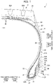
- FIG. 1 is a view showing a half section in a tire-width direction of a tire 1 according to the present embodiment.
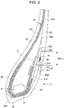
- FIG. 2 is an enlarged cross-sectional view of a portion on the inner side in the tire-radial direction of the tire 1 in FIG. 1 .
- the basic structure of the tire is left/right symmetric in the cross section of the tire-width direction; therefore, a cross-sectional view of the right half is shown herein.
- the reference symbol S1 is the tire equatorial plane.
- the tire equatorial plane S1 is a plane orthogonal to the tire rotation axis, and is positioned in the center of the tire-width direction.
- tire-width direction is a direction parallel to the tire rotation axis, and is the left/right direction of the paper plane of the cross-sectional view in FIG. 1 .
- it is illustrated as the tire-width direction X.
- inner-side of tire-width direction is a direction approaching the tire equatorial plane S1, and is the left side of the paper plane in FIG. 1 .
- Outer side of tire-width direction is a direction distancing from the tire equatorial plane S1, and is the right side of the paper plane in FIG. 1 .
- tire-radial direction is a direction perpendicular to the tire rotation axis, and is the vertical direction in the paper plane of FIG. 1 .
- FIG. 1 it is illustrated as the tire-width direction X.
- inner-side of tire-width direction is a direction approaching the tire equatorial plane S1, and is the left side of the paper plane in FIG. 1 .
- Outer side of tire-width direction is a
- tire-radial direction Y it is illustrated as the tire-radial direction Y.
- outer-side of tire-radial direction is a direction distancing from the tire rotation axis, and is the upper side of the paper plane in FIG. 1 .
- Inner-side of tire-radial direction is a direction approaching the tire rotation axis, and is the lower side of the paper plane in FIG. 1 .
- FIGS. 2 and 5 the same also applies to FIGS. 2 and 5 .
- the tire 1 is a tire for trucks and buses, for example, and includes a pair of beads 11 provided at both sides in the tire width direction, tread 12 forming a contact patch with the road surface, and a pair of sidewalls 13 which extends between the pair of beads 11 and the tread 12.
- the bead 11 includes an annular bead core 21 formed by wrapping around several times bead wires made of metal coated with rubber, and a bead filler 22 of tapered shape extending to the outer side in the tire-radial direction of the bead core 21.
- the bead core 21 is a member which plays a role of fixing a tire 1 filled with air to the rim of a wheel which is not illustrated.
- the bead filler 22 is a member provided in order to raise the rigidity of the peripheral part of the bead 11 and to ensure high maneuverability and stability.
- a carcass ply 23 constituting a ply serving as the skeleton of the tire is embedded inside of the tire 1.
- the carcass ply 23 extends from one bead core 21 to the other bead core 21.
- the carcass ply 23 is embedded in the tire 1 between the pair of bead cores 21, in a form passing through the pair of side walls 13 and the tread 12.
- the carcass ply 23 includes a ply body 24 which extends from one bead core 21 to the other bead core 21, and extends between the tread 12 and bead 11, and a ply folding part 25 which is folded around the bead core 21.
- a folding end 25A of the ply folding part 25 is positioned more to an inner side in the tire-radial direction than a tire-radial direction outside end 22A of the bead filler 22.
- the carcass ply 23 is configured by a plurality of ply cords extending in a tire-width direction.
- a plurality of ply cords is arranged side by side in a tire circumferential direction.
- This ply cord is configured by a metal steel cord, or an insulated organic fiber cord such as polyester or polyamide, or the like, and is covered by rubber.
- a plurality of layers of steel belts 26 is provided in the outer side in the tire radial direction of the carcass ply 23.
- the steel belt 26 is configured by a plurality of steel cords covered by rubber.
- the tread rubber 28 is provided at the outer side in the tire-radial direction of the steel belt 26.
- a tread pattern 28A is provided to the outer surface of the tread rubber 28.
- the outer surface of the tread rubber 28 serves as a contact surface which contacts with the road surface.
- a shoulder pad 38 is provided in the vicinity of the outer side in the tire-width direction of the tread 12, in a region between the carcass ply 23, and the steel belts 26 / tread rubber 28, a shoulder pad 38 is provided.
- the shoulder pad 38 extends until a region of the outer side in the tire-radial direction of the side wall 13, and part thereof forms an interface between side wall rubber 30 described later.
- a part of the shoulder pad 38 is present on the inner side in the tire width direction of the side wall rubber 30.
- the shoulder pad 38 consists of a rubber member having cushioning, and exhibits a cushion function between the carcass ply 23 and steel belt 26.
- the shoulder pad 38 consists of rubber having a characteristic of low heat buildup, it is possible to suppress heat generation effectively, by extending until the side wall 13.
- an inner liner 29 serving as a rubber layer constituting an inside wall surface of the tire 1 is provided to a tire inner cavity side of the carcass ply 23.
- the inner liner 29 is configured by air permeation resistant rubber, whereby the air inside the tire inner cavity is prevented from leaking to outside.
- the side wall rubber 30 constituting the outer wall surface of the tire 1 is provided to the outer side in the tire-width direction of the carcass ply 23.
- This side wall rubber 30 is a portion which bends the most upon the tire 1 exhibiting a cushioning action, and usually flexible rubber having fatigue resistance is adopted therein.
- a steel chafer 31 serving as a reinforcement ply is provided so as to cover at least part of the carcass ply 23.
- the steel chafer 31 also extends to the outer side in the tire-width direction of the ply folding part 25 of the carcass ply 23.
- the end 31A on the outer side in the tire-width direction of the steel chafer 31 is positioned more to the inner side in the tire-radial direction than the folding end 25A of the carcass ply 23.
- the end 29A on the inner side in the tire-radial direction of the aforementioned inner liner 29 curves so as to cover a portion of a corner on the inner side in the tire-width direction of the steel chafer 31.
- the steel chafer 31 is a metal reinforcement layer configured by a steel cord made of metal, and is covered by rubber.
- the rim strip rubber 32 is provided at the inner side in the tire-radial direction of the steel chafer 31.
- the rim strip rubber 32 is provided in a form such that covers the bead core 21 from the inner side in the tire-radial direction.
- the rim strip rubber 32 covers the end 29A on the inner side in the tire-radial direction of the inner liner 29.
- the rim strip rubber 32 is arranged along the outer surface of the tire, and connects with the side-wall rubber 30.
- the rim strip rubber 32 and side-wall rubber 30 are rubber members constituting the outer surface of the tire.
- a first pad 35 is provided at the outer side in the tire-radial direction of the end part 31A of the steel chafer 31, which is at the outer side in the tire-width direction of the folding part 25 of the carcass ply 23 and bead filler 22, a first pad 35 is provided.
- the first pad 35 is provided to the outer side in the tire-width direction of at least the folding end 25A of the carcass ply 23.
- the outer side in the tire-radial direction of the first pad 35 is formed so as to taper as approaching the outer side in the tire-radial direction.
- the first pad 35 has a portion with a thickness of at least 2 mm.
- the first pad 35 has non-uniform thickness.
- the cross-sectional shape of the first pad 35 has thick places and thin places.
- a second pad 36 is provided so as to cover the outer side in the tire-width direction of the first pad 35.
- the second pad 36 is provided so as to cover the outer side in the tire-width direction of part of the steel chafer 31, the first pad 35, and part of the bead filler 22.
- the outer side in the tire-radial direction of the second pad 36 is formed so as to taper as approaching the outer side in the tire-radial direction.
- the inner side in the tire-radial direction of the second pad 36 is formed so as to taper as approaching the inner side in the tire-radial direction.
- the position of the tire-radial direction outside end 36A of the second pad 36 is positioned more to the outer side in the tire-radial direction than the position of the tire-radial direction outside end 35A of the first pad 35.
- the second pad 36 has a portion with a thickness of at least 2 mm.
- the second pad 36 has a non-uniform thickness.
- the cross-sectional shape of the second pad 36 has a thick place and a thin place.
- the side-wall rubber 30 is arranged at the outer side in the tire-width direction in a region of the outer side in the tire-radial direction of the second pad 36, and the rim strip rubber 32 is arranged at an outer side in the tire-width direction in a region on the inner side in the tire-radial direction of the second pad 36.
- the side-wall rubber 30 covers a part on the outer side in the tire-width direction of the rim strip rubber 32 and a part on the outer side in the tire-width direction of the second pad 36.
- the first pad 35 and second pad 36 configure a pad member 34, and this pad member 34 is configured from rubber of modulus equal or higher than the modulus of the bead filler 22.
- the second pad 36 is configured by rubber of equal to or higher modulus than the bead filler 22, and the first pad 35 is configured by rubber of even higher modulus than the second pad 36.
- the first pad 35 and second pad 36 have a function of mitigating sudden distortion caused by the local rigidity point of change at the folding end 25A of the carcass ply 23 and the end part 31A of the steel chafer 31.
- the rubber sheet 37 serving as a reinforced rubber sheet is arranged in the vicinity of the folding end 25A of the carcass ply 23, between the bead filler 22 and pad member 34.
- the rubber sheet 37 is arranged so as to cover the folding end 25A of the carcass ply 23 from the inner side in the tire-width direction.
- the rubber sheet 37 is configured from rubber of higher modulus than the bead filler 22. More preferably, it is configured from rubber of a modulus substantially equal to that of the first pad 35.
- the rubber sheet 37 serving as the aforementioned reinforced rubber sheet, it becomes possible to effectively suppress the concentration of stress.
- the rubber sheet 37 preferably adopts a form arranged so as to cover the folding end 25A of the carcass ply 23 from the inner side in the tire-width direction as shown in FIG. 2 ; however, a configuration covering the folding end 25A of the carcass ply 23 from the outer side in the tire-width direction may be adopted. Even in this case, it is possible to mitigate the concentration of stress.
- the rubber sheet 37 is a sheet having a thickness of no more than 2 mm.
- the rubber sheet 37 has a constant thickness.
- the rubber sheet 37 has a cross-sectional shape prior to pasting which is a rectangular shape.
- the rim strip rubber 32 is arranged at least at the tire-width direction outer side of the ply folding part 25 of the carcass ply 23 folded back around the bead core 21.
- the rim strip rubber 32 covers a part of the tire-width direction outer side of the pad member 34 arranged at the outer side in the tire-width direction of the folding part 25 of the carcass ply 23.
- the rim strip rubber 32 covers the end 29A on the inner side in the tire-radial direction of the inner liner 29 covering a portion of a corner on the inner side in the tire-width direction of the steel chafer 31.
- the sidewall rubber 30 covers a part on the outer side in the tire-width direction of the rim strip rubber 32, and a part on the outer side in the tire-width direction of the pad member 34.
- the side-wall rubber 30 is preferably established with a modulus of 0.4 to 0.7 times that of the second pad 36.
- the first pad 35 is preferably established with a modulus of 1.0 to 1.2 times that of the second pad 36.
- the rim strip rubber 32 is preferably established with a modulus of 0.8 to 1.2 times that of the second pad 36.
- the RFID tag 40 as an electronic component is embedded in the tire 1 of the present embodiment.
- FIG. 3A shows an example of the RFID tag 40 according to the present embodiment.
- the RFID tag 40 is covered by the protective member 43.
- the RFID tag 40 is covered and hidden by the coating rubber sheet 431 configuring the protective member 43.
- FIG. 3B is a cross-sectional view along the line b-b in FIG. 3A
- FIG. 3C is a cross-sectional view along the line c-c in FIG. 3A .
- the RFID tag 40 is covered by the coating rubber sheets 431, 432 configuring the protective member 43.
- the RFID tag 40 is a passive-type transponder equipped with an RFID chip 41, and a plurality of antennas 42 for performing communication with external equipment.
- the RFID tag 40 performs wireless communication with a reader (not illustrated) as the external equipment.
- a storage part inside the RFID chip 41 identification information such as a manufacturing number and part number is stored.
- a coil-shaped spring antenna As the antenna 42, a coil-shaped spring antenna, plate-shaped antenna, and various types of rod-shaped antennas can be used. In addition, it may be an antenna formed by printing a predetermined pattern on a flexible substrate. When considering the communicability and flexibility, a coil-shaped spring antenna is the most preferable as the antenna 42.
- the antenna 42 is set to the optimized antenna length according to the frequency band, etc. used.
- the protective member 43 is configured from two coating rubber sheets 431, 432 which interpose and protect the RFID tag 40.
- the RFID tag 40 As shown in FIGS. 3A to 3C , the RFID tag 40 according to the present embodiment has a structure in which two thin pin-shaped antennas 42 extend mostly concentrically at both sides of the RFID chip 41. For this reason, the RFID tag 40 has a longitudinal direction which is long in the extending direction of the two antennas 42.
- the protective member 43 has a thin band-like shape which generally follows the shape of the RFID tag 40.
- the RFID tag 40 is embedded between the second pad 36 an rim strip rubber 32.
- the RFID tag 40 is embedded between the second pad 36 and rim strip rubber 32, at a position neighboring the tire-radial direction outside end 32A of the rim strip rubber 32, and covered by the end 30B on the inner side in the tire-radial direction of the side-wall rubber 30.
- the RFID tag 40 is preferably embedded between the second pad 36 and rim strip rubber 32, so that the longitudinal direction thereof becomes the direction of the tangential line relative to the circumferential direction of the tire 1, i.e. direction orthogonal to the paper plane of the cross-sectional view of FIGS. 1 and 2 .
- the RFID tag 40 includes the RFID chip 41, and antenna 42 extending linearly from the RFID chip 41 to both side of the RFID chip 41, and a central axis of the antenna 42 overlaps with the RFID chip 41.
- rubber having a modulus equivalent to at least the second pad 36 or a lower modulus is used.
- rubber which can be used in the protective member 43 if establishing the modulus of the second pad 36 as a reference, it is preferable to use rubber with a modulus of 0.7 to 1.1 times that.
- the RFID tag 40 By being covered by the coating rubber sheet (431, 432) constituting the protective member 43 in this way, the RFID tag 40 hardly receives direct stress generated during deformation of the tire 1, and for this reason, deforming and breaking are suppressed and communication performance is maintained.
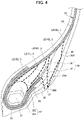
- FIG. 4 is an enlarged cross-sectional view showing the results of in-plane distribution simulation of strain energy, in a case of assembling the tire including the rubber structure resembling the rubber structure of the tire 1 according to the present embodiment to a rim, and applying 100% load.
- the same reference symbol is attached to constituent elements identical to the tire 1 according to the present embodiment shown in FIGS. 1 and 2 .
- the bead filler 22 is configured from a first bead filler 221 covering an outer circumference of the bead core 21, and a second bead filler 222 arranged at the outer side in the tire-radial direction of the first bead filler 221.
- the second bead filler 222 is configured from rubber of higher modulus than the inner liner 29 and side-wall rubber 30.
- the first bead filler 221 is configured from rubber of even higher modulus than the second bead filler 222.
- FIG. 4 displays by dividing the region in five, according to the magnitude of the strain energy.
- a region having the highest strain energy is defined as level 5
- a region having high strain energy is defined as level 4
- a region in which the strain energy somewhat declined is defined as level 3
- a region in which the strain energy further declined is defined as level 2
- the region in which the strain energy declined the most is defined as level 1.
- FIG. 4 displays by dividing the regions with bold dotted lines as the boundary.
- an outer side in the tire-radial direction becomes a region of mostly level 1, and is a region having low strain energy, and thus is preferable upon arranging the RFID tag 40.
- the results of the shear strain value decreasing by on the order of 15% is obtained by simulation. Due to being embedded at a position at which distortion hardly concentrates in this way, an improvement in the durability of the RFID tag 40 is achieved.
- the region of level 1 is on the outer side in the tire-width direction, and neighbors the side-wall 13; therefore, sufficient communication performance is exhibited.
- the RFID tag 40 is installed prior to the vulcanization step in the manufacturing process of the tire.
- the RFID tag 40 is installed at a portion corresponding to the position shown in FIG. 2 of the second pad 36 or rim strip rubber 32 prior to being vulcanized.
- the RFID tag 40 may be pasted to the second pad 36 or rim strip rubber 32 using the adhesiveness thereof.
- the adhesiveness being low or the like, it may be pasted using an adhesive or the like.
- the RFID tag 40 is interposed by the second pad 36 and rim strip rubber 32.
- the first pad 35 and second pad 36 are arranged as a two-layer rubber member between the RFID tag 40 and ply folding part 25 of the carcass ply 23. For this reason, even if deformation occurs in the first pad 35 by the ply folding part 25 in the aforementioned turn-up process, for example, the stress from this deformation is mitigated by the second pad 36 and hardly acts on the RFID tag 40.
- the RFID tag 40 hardly moves and is retained at a set position, a result of which an improvement in layout precision of the RFID tag 40 is thereby achieved.
- a gap hardly occurs between the second pad 36 and rim strip rubber 32, or the occurring gap is small. For this reason, rubber flows into this gap during vulcanization, and the shape of the second pad 36 and/or rim strip rubber 32 is suppressed from deforming.
- the manufacturing method of the tire 1 according to the present embodiment includes: a step of interposing the RFID tag 40 between the second pad 36 and rim strip rubber 32; and a step of folding back the RFID tag 40 and each constituent member including at least the first pad 35, second pad 36, rim strip rubber 32 and side-wall rubber 30 so as to surround the bead core 21 and bead filler 22, as mentioned above. It is thereby possible to arrange the RFID tag 40 so as to hardly receive influence from the carcass ply 23.
- the position of the tire-radial direction outside end 36A of the second pad 36 is located more to the outer side in the tire-radial direction than the position of the tire-radial direction outside end 35A of the first pad 35.
- the first pad 35 is held down to the second pad 36 during the aforementioned molding step of the tire 1 and deformation is suppressed, a result of which the RFID tag 40 comes to even more hardly move, and it is thereby possible to effectively obtain an improvement in layout precision.
- the side-wall rubber 30 covers part on the outer side in the tire-width direction of the rim strip rubber 32 and part on the outer side in the tire-width direction of the second pad 36. Since the boundary between the second pad 36 and rim strip rubber 32 is covered by the side-wall rubber 30, the position of the RFID tag 40 embedded at the boundary surface between the rim strip rubber 32 and second pad 36 is strongly retained.
- the RFID tag 40 according to the present embodiment is preferably arranged in the following such predetermined region at the boundary surface between the second pad 36 and rim strip rubber 32.
- the distance from the folding end 25A of the ply folding part 25 of the carcass ply 23 is set to at least 5 mm.
- the RFID tag 40 is arranged at a position distanced at least 5 mm from the folding end 25A.
- the distance D is specifically set on the order of 15 mm. Since the RFID tag 40 comes to even more hardly receive the influence from the carcass ply 23 during the aforementioned molding step of the tire 1, it is thereby possible to more effectively obtain an improvement in layout precision.
- the distance D is secured at 5 mm or greater in the tire 1 after molding. Therefore, at a stage before molding, the position of the RFID tag 40 is adjusted so that the distance D after molding is secured at 5 mm or greater.
- the RFID tag 40 is arranged in a region from the tire-radial direction outside end 32A of the rim strip rubber 32 until 20 mm to the inner side in the tire-radial direction.
- the RFID tag 40 is thereby embedded at a position at which distortion hardly concentrates; therefore, an improvement in durability is achieved.
- the RFID tag 40 is arranged with a distance on the order of 10 mm from the tire-radial direction outside end 32A of the rim strip rubber 32 to the inner side in the tire-radial direction. It should be noted that, for the RFID tag 40, as shown in FIG.
- the entirety thereof may be arranged in a region from the tire-radial direction outside end 32A of the rim strip rubber 32 until 20 mm to the inner side in the tire-radial direction, and at least a part thereof may be arranged in this region.
- the entirety of the coating rubber sheets 431, 432 may be arranged in a region from the tire-radial direction outside end 32A of the rim strip rubber 32 until 20 mm to the inner side in the tire-radial direction.
- the RFID tag 40 it is thereby possible to arrange the RFID tag 40 so as to hardly receive influence from the carcass ply 23, and possible to achieve an improvement in layout precision of the RFID tag 40.
- due to being embedded at a position at which distortion hardly concentrates it is possible to improve the durability of the RFID tag 40.
- the RFID tag 40 since the RFID tag 40 is embedded at a position on the outer side in the tire-width direction and contacting the side-wall 13, sufficient communication performance of the RFID tag 40 is exhibited.
- the position of the tire-radial direction outside end 36A of the second pad 36 is located more to the outer side in the tire-radial direction than the position of the tire-radial direction outside end 35A of the first pad 35.
- the first pad 35 is held down to the second pad 36 during the molding step of the tire 1 and deformation is suppressed, a result of which the RFID tag 40 comes to even more hardly move, and it is thereby possible to effectively obtain an improvement in layout precision.
- the RFID tag 40 is arranged at a position distanced by at least 5 mm from the folding end 25A of the carcass ply 23.
- the RFID tag 40 comes to even more hardly receive the influence from the carcass ply 23 during the molding step of the tire 1, it is thereby possible to more effectively obtain an improvement in layout precision. In addition, even in the case of the carcass ply 23 being made of metal, it is possible to maintain the communication performance of the RFID tag 40.
- the RFID tag 40 at least a part thereof is arranged in a region from the tire-radial direction outside end 32A of the rim strip rubber 32 until 20 mm to the inner side in the tire-radial direction.
- the RFID tag 40 is thereby embedded at a position at which distortion hardly concentrates; therefore, an improvement in durability is achieved.
- the tire 1 according to the present embodiment includes the side-wall rubber 30, and this side-wall rubber 30 is positioned at the outer side in the tire-width direction of at least part of part on the outer side in the tire-width direction of the rim strip rubber 32, and the second pad 36.
- the RFID tag 40 is covered by the coating rubber sheets 431, 432 constituting the protective member 43.
- the RFID tag 40 thereby hardly receives direct stress generated during deformation of the tire 1, and for this reason, deforming and breaking are suppressed and communication performance is maintained.
- the rim strip rubber 32 is preferably established with a modulus of 0.8 to 1.2 times that of this second pad 36.
- the coating rubber sheets 431, 432 covering the RFID tag 40 is preferably rubber having a modulus of 0.7 to 1.1 times that of the second pad 36.
- the RFID tag 40 thereby hardly receives direct stress generated during deformation of the tire 1, and for this reason, deforming and breaking are suppressed and communication performance is maintained.
- the steel chafer 31 is provided so as to cover at least part of the carcass ply 23, and the rim strip rubber 32 is provided at the inner side in the tire-radial direction of the steel chafer 31.
- the carcass ply 23 is thereby reinforced by the steel chafer 31, and the steel chafer 31 is protected by the rim strip rubber 32.
- An RFID tag 40 of the other embodiment shown in FIG. 5 is arranged more to the inner side in the tire-radial direction than in the above-mentioned embodiment.
- This RFID tag 40 is arranged at a position almost identical to the end 30B on the inner side in the radial direction of the side-wall rubber 30 in the tire-radial direction, which is a position somewhat more to the inner side in the tire-radial direction than the folding end 25A of the ply folding part 25 of the carcass ply 23.
- it is equipped with the same configuration as the above-mentioned embodiment.
- the RFID tag 40 is provided between the second pad 36 and rim strip rubber 32; therefore, the effect of the above (1) is similarly exerted. In addition, the effects of the above (2), (5) and (6) are also similarly exerted.
- the RFID tag 40 is covered by the coating rubber sheets 431, 432 constituting the protective member 43; however, it may be embedded to be sandwiched directly between the second pad 36 and rim strip rubber 32, without covering by the coating rubber sheets 431, 432.
- the RFID tag 40 is embedded in the tire as an electronic component; however, the electronic component according to the present invention embedded in the tire is not limited to an RFID tag.
- the electronic component according to the present invention embedded in the tire is not limited to an RFID tag.
- it may be various electronic components, piezoelectric elements, or strain sensors such as sensors performing wireless communication.
- the tire of the present invention can be adopted as various types of tires such as for cars, light trucks, trucks and buses, it is particularly suitable as a tire of a truck, bus, etc.
Landscapes
- Engineering & Computer Science (AREA)
- Mechanical Engineering (AREA)
- Tires In General (AREA)
Applications Claiming Priority (1)
| Application Number | Priority Date | Filing Date | Title |
|---|---|---|---|
| JP2020179382A JP7599903B2 (ja) | 2020-10-27 | 2020-10-27 | タイヤ |
Publications (2)
| Publication Number | Publication Date |
|---|---|
| EP3991993A1 true EP3991993A1 (fr) | 2022-05-04 |
| EP3991993B1 EP3991993B1 (fr) | 2023-03-29 |
Family
ID=78649111
Family Applications (1)
| Application Number | Title | Priority Date | Filing Date |
|---|---|---|---|
| EP21204606.4A Active EP3991993B1 (fr) | 2020-10-27 | 2021-10-26 | Pneumatique |
Country Status (4)
| Country | Link |
|---|---|
| US (1) | US11858298B2 (fr) |
| EP (1) | EP3991993B1 (fr) |
| JP (1) | JP7599903B2 (fr) |
| CN (1) | CN114475097B (fr) |
Cited By (1)
| Publication number | Priority date | Publication date | Assignee | Title |
|---|---|---|---|---|
| EP4523929A1 (fr) * | 2023-09-14 | 2025-03-19 | Sumitomo Rubber Industries, Ltd. | Pneu pour poids lourds |
Families Citing this family (3)
| Publication number | Priority date | Publication date | Assignee | Title |
|---|---|---|---|---|
| JP7457519B2 (ja) * | 2020-02-18 | 2024-03-28 | 株式会社ブリヂストン | 航空機用タイヤ |
| JP7283617B1 (ja) * | 2022-06-24 | 2023-05-30 | 住友ゴム工業株式会社 | 重荷重用タイヤ |
| JP2025115449A (ja) * | 2024-01-26 | 2025-08-07 | 横浜ゴム株式会社 | タイヤ及びその製造方法 |
Citations (4)
| Publication number | Priority date | Publication date | Assignee | Title |
|---|---|---|---|---|
| JP6276859B2 (ja) | 2013-12-13 | 2018-02-07 | ブリヂストン アメリカズ タイヤ オペレーションズ、 エルエルシー | 下部サイドウォール内に電子デバイスを有するタイヤ |
| WO2019180358A1 (fr) * | 2018-03-22 | 2019-09-26 | Compagnie Generale Des Etablissements Michelin | Pneumatique poids-lourd equipe d'un module de communication radiofrequence |
| WO2019220063A2 (fr) * | 2018-05-17 | 2019-11-21 | Compagnie Generale Des Etablissements Michelin | Procede de fabrication d'un pneumatique equipe d'un module de communication radiofrequence |
| US20200108676A1 (en) * | 2018-10-03 | 2020-04-09 | Toyo Tire Corporation | Tire |
Family Cites Families (19)
| Publication number | Priority date | Publication date | Assignee | Title |
|---|---|---|---|---|
| JP4567180B2 (ja) * | 2000-12-18 | 2010-10-20 | 住友ゴム工業株式会社 | 重荷重用タイヤ |
| EP1767383A1 (fr) * | 2001-01-11 | 2007-03-28 | Sumitomo Rubber Industries, Ltd. | Bandage pneumatique |
| JP2004106796A (ja) * | 2002-09-20 | 2004-04-08 | Sumitomo Rubber Ind Ltd | ゴム組成物および空気入りタイヤ |
| JP2007081632A (ja) * | 2005-09-13 | 2007-03-29 | Nec Tokin Corp | 無線icタグ |
| FR2914585B1 (fr) * | 2007-04-03 | 2009-07-03 | Michelin Soc Tech | Pneumatique comprenant un organe electronique et procede de fabrication d'un tel pneumatique |
| JP4567763B2 (ja) * | 2008-03-25 | 2010-10-20 | 住友ゴム工業株式会社 | 重荷重用タイヤ |
| JP5438474B2 (ja) * | 2009-11-13 | 2014-03-12 | 住友ゴム工業株式会社 | 重荷重用空気入りタイヤ及びその製造方法 |
| JP5858069B2 (ja) * | 2014-03-06 | 2016-02-10 | 横浜ゴム株式会社 | 空気入りタイヤ |
| JP6754168B2 (ja) * | 2014-08-08 | 2020-09-09 | 株式会社ブリヂストン | タイヤ |
| JP6423653B2 (ja) * | 2014-09-01 | 2018-11-14 | 株式会社ブリヂストン | タイヤ |
| JP6686465B2 (ja) * | 2016-01-21 | 2020-04-22 | 横浜ゴム株式会社 | タイヤ劣化判定具、タイヤ劣化判定具を備えた空気入りタイヤ、タイヤ劣化判定方法及びタイヤ更生可否判定方法 |
| JP6639015B2 (ja) * | 2016-06-16 | 2020-02-05 | 株式会社ブリヂストン | 空気入りタイヤ |
| JP6800695B2 (ja) * | 2016-10-14 | 2020-12-16 | Toyo Tire株式会社 | タイヤの製造方法 |
| FR3059605A1 (fr) * | 2016-12-05 | 2018-06-08 | Compagnie Generale Des Etablissements Michelin | Enveloppe pneumatique equipee d''un organe electronique |
| JP6311810B1 (ja) * | 2017-02-28 | 2018-04-18 | 横浜ゴム株式会社 | 空気入りタイヤ |
| DE102017209541A1 (de) * | 2017-06-07 | 2018-12-13 | Continental Reifen Deutschland Gmbh | Fahrzeugreifen |
| US10310447B2 (en) * | 2017-07-12 | 2019-06-04 | Canon Kabushiki Kaisha | Electrophotographic member, process cartridge, and electrophotographic image forming apparatus |
| JP6529701B1 (ja) * | 2017-09-12 | 2019-06-12 | 住友ゴム工業株式会社 | 空気入りタイヤ |
| JP6698194B1 (ja) * | 2019-04-24 | 2020-05-27 | Toyo Tire株式会社 | タイヤおよびタイヤの製造方法 |
-
2020
- 2020-10-27 JP JP2020179382A patent/JP7599903B2/ja active Active
-
2021
- 2021-10-21 CN CN202111225243.1A patent/CN114475097B/zh active Active
- 2021-10-26 EP EP21204606.4A patent/EP3991993B1/fr active Active
- 2021-10-27 US US17/512,287 patent/US11858298B2/en active Active
Patent Citations (4)
| Publication number | Priority date | Publication date | Assignee | Title |
|---|---|---|---|---|
| JP6276859B2 (ja) | 2013-12-13 | 2018-02-07 | ブリヂストン アメリカズ タイヤ オペレーションズ、 エルエルシー | 下部サイドウォール内に電子デバイスを有するタイヤ |
| WO2019180358A1 (fr) * | 2018-03-22 | 2019-09-26 | Compagnie Generale Des Etablissements Michelin | Pneumatique poids-lourd equipe d'un module de communication radiofrequence |
| WO2019220063A2 (fr) * | 2018-05-17 | 2019-11-21 | Compagnie Generale Des Etablissements Michelin | Procede de fabrication d'un pneumatique equipe d'un module de communication radiofrequence |
| US20200108676A1 (en) * | 2018-10-03 | 2020-04-09 | Toyo Tire Corporation | Tire |
Cited By (1)
| Publication number | Priority date | Publication date | Assignee | Title |
|---|---|---|---|---|
| EP4523929A1 (fr) * | 2023-09-14 | 2025-03-19 | Sumitomo Rubber Industries, Ltd. | Pneu pour poids lourds |
Also Published As
| Publication number | Publication date |
|---|---|
| US20220126634A1 (en) | 2022-04-28 |
| JP2022070361A (ja) | 2022-05-13 |
| JP7599903B2 (ja) | 2024-12-16 |
| CN114475097B (zh) | 2025-02-07 |
| CN114475097A (zh) | 2022-05-13 |
| EP3991993B1 (fr) | 2023-03-29 |
| US11858298B2 (en) | 2024-01-02 |
Similar Documents
| Publication | Publication Date | Title |
|---|---|---|
| US12194788B2 (en) | Tire | |
| EP3632712B1 (fr) | Pneumatique | |
| US11858298B2 (en) | Tire | |
| EP3632706B1 (fr) | Procédé de fabrication de pneumatique et pneumatique | |
| EP3632709B1 (fr) | Procédé de fabrication de pneumatique et pneumatique | |
| US11400769B2 (en) | Tire | |
| EP3632664B1 (fr) | Procédé de fabrication de pneu et pneu | |
| US11440355B2 (en) | Tire | |
| EP3730320B1 (fr) | Pneumatique | |
| JP7560994B2 (ja) | タイヤ | |
| EP3632708A1 (fr) | Pneumatique | |
| US20200108669A1 (en) | Tire | |
| US20200108574A1 (en) | Tire | |
| EP4019293B1 (fr) | Pneumatique | |
| EP3632707B1 (fr) | Procédé de fabrication de pneumatique et pneumatique | |
| JP2025059880A (ja) | 空気入りタイヤ及びその製造方法 |
Legal Events
| Date | Code | Title | Description |
|---|---|---|---|
| PUAI | Public reference made under article 153(3) epc to a published international application that has entered the european phase |
Free format text: ORIGINAL CODE: 0009012 |
|
| STAA | Information on the status of an ep patent application or granted ep patent |
Free format text: STATUS: REQUEST FOR EXAMINATION WAS MADE |
|
| 17P | Request for examination filed |
Effective date: 20211028 |
|
| AK | Designated contracting states |
Kind code of ref document: A1 Designated state(s): AL AT BE BG CH CY CZ DE DK EE ES FI FR GB GR HR HU IE IS IT LI LT LU LV MC MK MT NL NO PL PT RO RS SE SI SK SM TR |
|
| RIC1 | Information provided on ipc code assigned before grant |
Ipc: H01Q 7/00 20060101ALN20221010BHEP Ipc: H01Q 1/40 20060101ALI20221010BHEP Ipc: H01Q 1/38 20060101ALI20221010BHEP Ipc: H01Q 1/22 20060101ALI20221010BHEP Ipc: B60C 15/06 20060101ALI20221010BHEP Ipc: B60C 19/00 20060101AFI20221010BHEP |
|
| GRAP | Despatch of communication of intention to grant a patent |
Free format text: ORIGINAL CODE: EPIDOSNIGR1 |
|
| STAA | Information on the status of an ep patent application or granted ep patent |
Free format text: STATUS: GRANT OF PATENT IS INTENDED |
|
| INTG | Intention to grant announced |
Effective date: 20221118 |
|
| GRAS | Grant fee paid |
Free format text: ORIGINAL CODE: EPIDOSNIGR3 |
|
| GRAA | (expected) grant |
Free format text: ORIGINAL CODE: 0009210 |
|
| STAA | Information on the status of an ep patent application or granted ep patent |
Free format text: STATUS: THE PATENT HAS BEEN GRANTED |
|
| AK | Designated contracting states |
Kind code of ref document: B1 Designated state(s): AL AT BE BG CH CY CZ DE DK EE ES FI FR GB GR HR HU IE IS IT LI LT LU LV MC MK MT NL NO PL PT RO RS SE SI SK SM TR |
|
| REG | Reference to a national code |
Ref country code: CH Ref legal event code: EP |
|
| REG | Reference to a national code |
Ref country code: DE Ref legal event code: R096 Ref document number: 602021001754 Country of ref document: DE |
|
| REG | Reference to a national code |
Ref country code: AT Ref legal event code: REF Ref document number: 1556432 Country of ref document: AT Kind code of ref document: T Effective date: 20230415 |
|
| REG | Reference to a national code |
Ref country code: IE Ref legal event code: FG4D |
|
| REG | Reference to a national code |
Ref country code: LT Ref legal event code: MG9D |
|
| PG25 | Lapsed in a contracting state [announced via postgrant information from national office to epo] |
Ref country code: RS Free format text: LAPSE BECAUSE OF FAILURE TO SUBMIT A TRANSLATION OF THE DESCRIPTION OR TO PAY THE FEE WITHIN THE PRESCRIBED TIME-LIMIT Effective date: 20230329 Ref country code: NO Free format text: LAPSE BECAUSE OF FAILURE TO SUBMIT A TRANSLATION OF THE DESCRIPTION OR TO PAY THE FEE WITHIN THE PRESCRIBED TIME-LIMIT Effective date: 20230629 Ref country code: LV Free format text: LAPSE BECAUSE OF FAILURE TO SUBMIT A TRANSLATION OF THE DESCRIPTION OR TO PAY THE FEE WITHIN THE PRESCRIBED TIME-LIMIT Effective date: 20230329 Ref country code: LT Free format text: LAPSE BECAUSE OF FAILURE TO SUBMIT A TRANSLATION OF THE DESCRIPTION OR TO PAY THE FEE WITHIN THE PRESCRIBED TIME-LIMIT Effective date: 20230329 Ref country code: HR Free format text: LAPSE BECAUSE OF FAILURE TO SUBMIT A TRANSLATION OF THE DESCRIPTION OR TO PAY THE FEE WITHIN THE PRESCRIBED TIME-LIMIT Effective date: 20230329 |
|
| REG | Reference to a national code |
Ref country code: NL Ref legal event code: MP Effective date: 20230329 |
|
| REG | Reference to a national code |
Ref country code: AT Ref legal event code: MK05 Ref document number: 1556432 Country of ref document: AT Kind code of ref document: T Effective date: 20230329 |
|
| PG25 | Lapsed in a contracting state [announced via postgrant information from national office to epo] |
Ref country code: SE Free format text: LAPSE BECAUSE OF FAILURE TO SUBMIT A TRANSLATION OF THE DESCRIPTION OR TO PAY THE FEE WITHIN THE PRESCRIBED TIME-LIMIT Effective date: 20230329 Ref country code: NL Free format text: LAPSE BECAUSE OF FAILURE TO SUBMIT A TRANSLATION OF THE DESCRIPTION OR TO PAY THE FEE WITHIN THE PRESCRIBED TIME-LIMIT Effective date: 20230329 Ref country code: GR Free format text: LAPSE BECAUSE OF FAILURE TO SUBMIT A TRANSLATION OF THE DESCRIPTION OR TO PAY THE FEE WITHIN THE PRESCRIBED TIME-LIMIT Effective date: 20230630 Ref country code: FI Free format text: LAPSE BECAUSE OF FAILURE TO SUBMIT A TRANSLATION OF THE DESCRIPTION OR TO PAY THE FEE WITHIN THE PRESCRIBED TIME-LIMIT Effective date: 20230329 |
|
| PG25 | Lapsed in a contracting state [announced via postgrant information from national office to epo] |
Ref country code: SM Free format text: LAPSE BECAUSE OF FAILURE TO SUBMIT A TRANSLATION OF THE DESCRIPTION OR TO PAY THE FEE WITHIN THE PRESCRIBED TIME-LIMIT Effective date: 20230329 Ref country code: RO Free format text: LAPSE BECAUSE OF FAILURE TO SUBMIT A TRANSLATION OF THE DESCRIPTION OR TO PAY THE FEE WITHIN THE PRESCRIBED TIME-LIMIT Effective date: 20230329 Ref country code: PT Free format text: LAPSE BECAUSE OF FAILURE TO SUBMIT A TRANSLATION OF THE DESCRIPTION OR TO PAY THE FEE WITHIN THE PRESCRIBED TIME-LIMIT Effective date: 20230731 Ref country code: ES Free format text: LAPSE BECAUSE OF FAILURE TO SUBMIT A TRANSLATION OF THE DESCRIPTION OR TO PAY THE FEE WITHIN THE PRESCRIBED TIME-LIMIT Effective date: 20230329 Ref country code: EE Free format text: LAPSE BECAUSE OF FAILURE TO SUBMIT A TRANSLATION OF THE DESCRIPTION OR TO PAY THE FEE WITHIN THE PRESCRIBED TIME-LIMIT Effective date: 20230329 Ref country code: AT Free format text: LAPSE BECAUSE OF FAILURE TO SUBMIT A TRANSLATION OF THE DESCRIPTION OR TO PAY THE FEE WITHIN THE PRESCRIBED TIME-LIMIT Effective date: 20230329 |
|
| PG25 | Lapsed in a contracting state [announced via postgrant information from national office to epo] |
Ref country code: SK Free format text: LAPSE BECAUSE OF FAILURE TO SUBMIT A TRANSLATION OF THE DESCRIPTION OR TO PAY THE FEE WITHIN THE PRESCRIBED TIME-LIMIT Effective date: 20230329 Ref country code: PL Free format text: LAPSE BECAUSE OF FAILURE TO SUBMIT A TRANSLATION OF THE DESCRIPTION OR TO PAY THE FEE WITHIN THE PRESCRIBED TIME-LIMIT Effective date: 20230329 Ref country code: IS Free format text: LAPSE BECAUSE OF FAILURE TO SUBMIT A TRANSLATION OF THE DESCRIPTION OR TO PAY THE FEE WITHIN THE PRESCRIBED TIME-LIMIT Effective date: 20230729 |
|
| REG | Reference to a national code |
Ref country code: DE Ref legal event code: R097 Ref document number: 602021001754 Country of ref document: DE |
|
| PG25 | Lapsed in a contracting state [announced via postgrant information from national office to epo] |
Ref country code: DK Free format text: LAPSE BECAUSE OF FAILURE TO SUBMIT A TRANSLATION OF THE DESCRIPTION OR TO PAY THE FEE WITHIN THE PRESCRIBED TIME-LIMIT Effective date: 20230329 Ref country code: CZ Free format text: LAPSE BECAUSE OF FAILURE TO SUBMIT A TRANSLATION OF THE DESCRIPTION OR TO PAY THE FEE WITHIN THE PRESCRIBED TIME-LIMIT Effective date: 20230329 |
|
| PLBE | No opposition filed within time limit |
Free format text: ORIGINAL CODE: 0009261 |
|
| STAA | Information on the status of an ep patent application or granted ep patent |
Free format text: STATUS: NO OPPOSITION FILED WITHIN TIME LIMIT |
|
| 26N | No opposition filed |
Effective date: 20240103 |
|
| PG25 | Lapsed in a contracting state [announced via postgrant information from national office to epo] |
Ref country code: SI Free format text: LAPSE BECAUSE OF FAILURE TO SUBMIT A TRANSLATION OF THE DESCRIPTION OR TO PAY THE FEE WITHIN THE PRESCRIBED TIME-LIMIT Effective date: 20230329 |
|
| PG25 | Lapsed in a contracting state [announced via postgrant information from national office to epo] |
Ref country code: SI Free format text: LAPSE BECAUSE OF FAILURE TO SUBMIT A TRANSLATION OF THE DESCRIPTION OR TO PAY THE FEE WITHIN THE PRESCRIBED TIME-LIMIT Effective date: 20230329 Ref country code: IT Free format text: LAPSE BECAUSE OF FAILURE TO SUBMIT A TRANSLATION OF THE DESCRIPTION OR TO PAY THE FEE WITHIN THE PRESCRIBED TIME-LIMIT Effective date: 20230329 Ref country code: MC Free format text: LAPSE BECAUSE OF FAILURE TO SUBMIT A TRANSLATION OF THE DESCRIPTION OR TO PAY THE FEE WITHIN THE PRESCRIBED TIME-LIMIT Effective date: 20230329 |
|
| REG | Reference to a national code |
Ref country code: BE Ref legal event code: MM Effective date: 20231031 |
|
| PG25 | Lapsed in a contracting state [announced via postgrant information from national office to epo] |
Ref country code: LU Free format text: LAPSE BECAUSE OF NON-PAYMENT OF DUE FEES Effective date: 20231026 |
|
| PG25 | Lapsed in a contracting state [announced via postgrant information from national office to epo] |
Ref country code: LU Free format text: LAPSE BECAUSE OF NON-PAYMENT OF DUE FEES Effective date: 20231026 |
|
| PG25 | Lapsed in a contracting state [announced via postgrant information from national office to epo] |
Ref country code: BE Free format text: LAPSE BECAUSE OF NON-PAYMENT OF DUE FEES Effective date: 20231031 |
|
| PG25 | Lapsed in a contracting state [announced via postgrant information from national office to epo] |
Ref country code: IE Free format text: LAPSE BECAUSE OF NON-PAYMENT OF DUE FEES Effective date: 20231026 |
|
| PG25 | Lapsed in a contracting state [announced via postgrant information from national office to epo] |
Ref country code: IE Free format text: LAPSE BECAUSE OF NON-PAYMENT OF DUE FEES Effective date: 20231026 |
|
| PG25 | Lapsed in a contracting state [announced via postgrant information from national office to epo] |
Ref country code: BG Free format text: LAPSE BECAUSE OF FAILURE TO SUBMIT A TRANSLATION OF THE DESCRIPTION OR TO PAY THE FEE WITHIN THE PRESCRIBED TIME-LIMIT Effective date: 20230329 |
|
| PG25 | Lapsed in a contracting state [announced via postgrant information from national office to epo] |
Ref country code: BG Free format text: LAPSE BECAUSE OF FAILURE TO SUBMIT A TRANSLATION OF THE DESCRIPTION OR TO PAY THE FEE WITHIN THE PRESCRIBED TIME-LIMIT Effective date: 20230329 |
|
| REG | Reference to a national code |
Ref country code: CH Ref legal event code: PL |
|
| PG25 | Lapsed in a contracting state [announced via postgrant information from national office to epo] |
Ref country code: CH Free format text: LAPSE BECAUSE OF NON-PAYMENT OF DUE FEES Effective date: 20241031 |
|
| PG25 | Lapsed in a contracting state [announced via postgrant information from national office to epo] |
Ref country code: CY Free format text: LAPSE BECAUSE OF FAILURE TO SUBMIT A TRANSLATION OF THE DESCRIPTION OR TO PAY THE FEE WITHIN THE PRESCRIBED TIME-LIMIT; INVALID AB INITIO Effective date: 20211026 |
|
| PGFP | Annual fee paid to national office [announced via postgrant information from national office to epo] |
Ref country code: FR Payment date: 20250908 Year of fee payment: 5 |
|
| PG25 | Lapsed in a contracting state [announced via postgrant information from national office to epo] |
Ref country code: TR Free format text: LAPSE BECAUSE OF FAILURE TO SUBMIT A TRANSLATION OF THE DESCRIPTION OR TO PAY THE FEE WITHIN THE PRESCRIBED TIME-LIMIT Effective date: 20230329 |
|
| PGFP | Annual fee paid to national office [announced via postgrant information from national office to epo] |
Ref country code: DE Payment date: 20250902 Year of fee payment: 5 |
|
| PG25 | Lapsed in a contracting state [announced via postgrant information from national office to epo] |
Ref country code: HU Free format text: LAPSE BECAUSE OF FAILURE TO SUBMIT A TRANSLATION OF THE DESCRIPTION OR TO PAY THE FEE WITHIN THE PRESCRIBED TIME-LIMIT; INVALID AB INITIO Effective date: 20211026 |