EP3992113B1 - Récipient de collecte de système de recyclage - Google Patents
Récipient de collecte de système de recyclage Download PDFInfo
- Publication number
- EP3992113B1 EP3992113B1 EP21205012.4A EP21205012A EP3992113B1 EP 3992113 B1 EP3992113 B1 EP 3992113B1 EP 21205012 A EP21205012 A EP 21205012A EP 3992113 B1 EP3992113 B1 EP 3992113B1
- Authority
- EP
- European Patent Office
- Prior art keywords
- recycling system
- flap
- collecting container
- drop
- tray
- Prior art date
- Legal status (The legal status is an assumption and is not a legal conclusion. Google has not performed a legal analysis and makes no representation as to the accuracy of the status listed.)
- Active
Links
Images


Classifications
-
- B—PERFORMING OPERATIONS; TRANSPORTING
- B65—CONVEYING; PACKING; STORING; HANDLING THIN OR FILAMENTARY MATERIAL
- B65F—GATHERING OR REMOVAL OF DOMESTIC OR LIKE REFUSE
- B65F1/00—Refuse receptacles; Accessories therefor
- B65F1/10—Refuse receptacles; Accessories therefor with refuse filling means, e.g. air-locks
-
- B—PERFORMING OPERATIONS; TRANSPORTING
- B65—CONVEYING; PACKING; STORING; HANDLING THIN OR FILAMENTARY MATERIAL
- B65F—GATHERING OR REMOVAL OF DOMESTIC OR LIKE REFUSE
- B65F2240/00—Types of refuse collected
- B65F2240/128—Clothing
Definitions
- the invention relates to a recycling system collection container according to the preamble of claim 1.
- the invention relates to recycling system collection containers for collecting goods that are fed into a recycling system, such as old clothes.
- a recycling system such as old clothes.
- other goods can also be collected in such recycling system collection containers, such as electrical appliances, glass bottles, medicines, batteries, dog excrement, etc.
- Such recycling system collection containers typically have a drop-in device for throwing in the goods and a collection space provided below the drop-in device for receiving the thrown-in goods.
- the drop-in device comprises a drop-in tray onto which the goods to be collected can be placed.
- a recycling system collection container which provides a throw-in drum which is guided on rails, whereby the drum automatically rolls back to its throw-in position for throwing in goods to be collected due to the inclination of the rails if it has previously been in its transfer position for handing over thrown-in goods.
- the throw-in drum can be moved by a cable pull to ensure that the throw-in drum is manually driven.
- this solution does not completely rule out theft attempts.
- a collection container according to the preamble of claim 1 is known, which provides a drop-in tray which is first lifted by a cable pull when a closure element is closed and then tilted for emptying.
- the invention is therefore based on the object of making it even more difficult or impossible to enter the recycling system collection container via the insertion device.
- the invention solves this problem with the features of a recycling system collection container according to claim 1.
- the recycling system collection container for collecting goods to be recycled that are fed into a recycling system, such as old clothes, electrical appliances, glass bottles, medicines, batteries, dog excrement, etc., therefore has a throw-in device for throwing in the goods and a collection space provided below the throw-in device for receiving thrown-in goods, wherein the throw-in device comprises a throw-in tray.
- the recycling system collection container also comprises a carriage that can be moved along a rail guide. This carriage supports the throw-in tray so that it can rotate using at least one axis of rotation.
- the throw-in device also has a flap device.
- This flap device comprises a flap with at least one flap lever rigidly connected to it and at least one rod that is connected to the flap lever and the axis of rotation in such a way that actuation of the flap moves the carriage along the rail guide while simultaneously rotating the throw-in tray.
- the flap is operated by opening or closing the flap.
- the flap When the flap is opened, the carriage and the tray move into a Flap adjacent position to allow goods to be thrown into the throw-in tray.
- the flap When the flap is closed, the carriage including the throw-in tray moves to a position away from the flap to transfer the goods in the throw-in tray to the collection area.
- the invention therefore provides a mechanical construction in which the insertion tray is no longer accessible from the outside in its transfer position for transferring the inserted goods into the collection space, since the flap is closed in this transfer position. In contrast, access to the collection space is impossible when the flap is open, since in this state the insertion tray blocks access to the collection space from the outside.
- the invention substantially complicates entry into the recycling system collection container via the insertion device or excludes such entry.
- the invention thus increases the security of the collected goods against theft while simultaneously increasing the security of potential perpetrators who might attempt to steal collected goods from a recycling system collection container.
- the recycling system collection container has at least one lever rod, the first end of which is connected in an articulated manner to the insertion tray and the second end of which is connected in an articulated manner to a bearing point which is arranged in a fixed position in relation to the housing of the recycling system collection container.
- the recycling system collection container has a lower partition opposite the collection space, which comprises a lower partition wall and two side partition walls. This The lower partition prevents possible entry or access from outside into the collection area when the flap is only partially open.
- the insertion tray is mounted so that it can rotate using two axes of rotation.
- the carriage has two side walls, each of which accommodates one of the axes of rotation and which are guided in the rail guide. This structure allows the insertion tray to be mounted robustly, so that even if the insertion tray is loaded with heavy goods, the mechanical structure of the insertion device does not bend or become damaged in any other way.
- the slide has an upper partition that borders the two side walls of the slide. Similar to the lower partition, the upper partition also prevents possible entry or access from outside into the collecting space when the flap is only partially open.
- At least one spiral spring is attached at its first end to the upper partition or to the upper area of one of the two side walls of the carriage.
- the second end of the spiral spring is attached to the rod connected to the flap lever.
- the insertion tray has a curved base surface and two adjacent side surfaces. This allows collected goods to slide evenly into the collection space when the insertion tray rotates about its axis of rotation when moving to its position away from the flap for the purpose of emptying the insertion tray.
- the lever rod is connected with its first end to one of the side surfaces of the insertion tray in an articulated manner.
- the bearing point for the second end of the lever rod is on the lower Separation is arranged.
- the installation is advantageously carried out in such a way that the rail guide is arranged on the housing of the recycling system collection container at an angle to the horizontal.
- the inclination of the rail guide is selected in such a way that the insertion tray is moved diagonally upwards from the position next to the flap during insertion of goods to be collected to the position during emptying of the insertion tray into the collection area.
- the goods to be collected are thus transferred to the collection area from a higher position compared to the insertion position when the flap is open. This enables the recycling system collection container to be constructed higher and the volume of the collection area to be used efficiently.
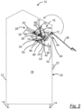
- Fig. 1 to 3 show an embodiment of a recycling system collection container 10 according to the invention.
- the housing 12 of the recycling system collection container 10 is shown in dashed lines and only schematically.
- the recycling system collection container 10 comprises several adjustable feet 14 in the lower area in order to compensate for any unevenness in the floor.
- the housing 12 accommodates a feed device 16, which is shown with solid lines. It is used to throw in the goods to be collected.
- the collection room 18 is accessible via a door 20 provided on the front, which can be closed by means of a lock 22.
- the insertion device 16 comprises an insertion tray 24 which can be moved by a carriage 26 along a rail guide 28.
- the rail guide comprises upper rails 30 and lower rails 32 arranged to the right and left sides of the insertion tray 24.
- the insertion tray 24 is rotatably mounted by means of rotary axes 34 guided in the rail guide 28.
- the insertion device 16 further comprises a flap device 36 with a flap 38 and one or two flap levers 40 rigidly connected laterally to the flap 38.
- the flap device 36 further comprises a rod 42 which is connected to the flap lever 40 and the rotation axis 34.
- the flap lever 40 With flap 38 open ( Fig. 1 ), the flap lever 40 is directed downwards and pulls the rod 42 in the direction of the opening 44 to be closed by the flap.
- the rod 42 also pulls the rotation axis 34 in the direction of this opening 44, so that the insertion tray 24 is in its outer position, in which goods to be collected can be placed into the insertion tray 24 via the opened flap 38.
- the flap lever 40 is further away from the Figures 1 and 2 shown positions and thereby achieves, for example, an essentially horizontal alignment.
- the rod pushes the axis of rotation 34 further up the rail guide 28 and the carriage 28 reaches its inner end position.
- the insertion tray 24 is not only moved from a position adjacent to the flap 38 ( Fig. 1 ) to a position remote from the flap 38 ( Fig. 3 ), but at the same time the insertion tray 24 is rotated so that when the aforementioned end position of the carriage 28 is reached, the insertion tray 24 has been rotated so far that the goods located on the insertion tray 24 are emptied in the direction of the collecting space 18.
- the insertion device 16 further comprises a lever rod 46 with two ends 48, 50.
- the first end 48 of the lever rod 46 is connected in an articulated manner to the insertion tray 24.
- the second end 50 of the lever rod 46 is connected in an articulated manner to a bearing point which is arranged stationary with respect to the housing 12 of the recycling system collection container 10.
- the insertion device 16 further comprises a lower partition 52 opposite the collecting space 18, which comprises a lower partition wall 54 and two lateral partition walls 56 adjoining the lower partition wall 54, which are each arranged to the left and right of the lower partition wall 54.
- the carriage 26 has two side walls 58, which in the embodiment shown, but not necessarily, have a triangular basic shape. These two side walls 58 each accommodate one of the axes of rotation 34, which are guided in the rail guide 28. Furthermore, a further sliding element 60 is provided on each of the two side walls 58, which is each guided in the rail guide 28. The sliding elements 60 and the axes of rotation 34 ensure that the side walls 58 of the carriage 26 retain their orientation while the carriage 26 is moved along the rail guide 28.
- the carriage 26 has an upper partition 62 which adjoins both side walls 58 of the carriage 26.
- this upper partition is formed by two partition walls 64, 66 arranged at an angle to one another.
- the insertion device 16 further comprises a spiral spring 68, the first end 70 of which is fastened to the upper partition 62 of the carriage 26 or to the upper region of one of the two side walls 58 of the carriage 26.
- the second end 72 of the spiral spring 68 is fastened to the rod 42 connected to the flap lever 40.
- the insertion tray 24 has a curved bottom surface 74 and two adjacent side surfaces 76.
- the lever rod 46 is connected in an articulated manner with its first end 48 to one of these side surfaces 76 of the insertion tray 24.
- the second end 50 of the lever rod 46 is connected in an articulated manner to the lower partition 52.
- the rail guide 28 is arranged at an angle on the housing 12 of the recycling system collection container 10 in the manner shown, so that the insertion tray 24 can be moved from its lower, outer position when the flap 38 is open ( Fig. 1 ) to its inner, upper position with the flap closed ( Fig. 3 ) is moved upwards. Thanks to the lever rod 46, the insertion tray 24 simultaneously rotates about the rotation axes 34, so that goods located on the insertion tray 24 are thrown into the collection space 18.
- the insertion device 16 ensures that in accordance with Fig. 1 With the flap 38 shown open, the collection chamber 18 is inaccessible from the outside via the opening 44, since the collection chamber is shielded by the insertion tray 24 and the upper partition 62.
- the invention therefore makes it substantially more difficult or impossible to gain access to a recycling system collection container 10 via the insertion device 16.
- Theft of the collected goods located in the collection area 18 is therefore no longer possible by accessing it via the insertion device 16.
- the invention thus significantly reduces the potential for theft of collected goods and therefore no longer gives potential thieves any reason to gain access to the collection area 18 of such recycling system collection containers 10 at the risk of their own lives.
Landscapes
- Engineering & Computer Science (AREA)
- Mechanical Engineering (AREA)
- Refuse Receptacles (AREA)
Claims (10)
- Conteneur de collecte d'un système de recyclage, destiné à collecter des produits revalorisables qui sont amenés vers un système de recyclage, tels que par exemple des vêtements portés, des appareils électriques, des bouteilles en verre, des médicaments, des piles, des déjections canines, etc., pourvu d'un système d'introduction (16) destiné à introduire les produits et d'un espace collecteur (18) prévu en-dessous du système d'introduction (16), destiné à recevoir les produits introduits, le système d'introduction (16) comportant une coque d'introduction (24),
caractérisé parun chariot (26), qui est déplaçable le long d'un guidage par glissière (28) et qui loge en rotation la coque d'introduction (24) au moyen d'au moins un axe de rotation (34),le système d'introduction (16) comportant par ailleurs un système de volet (36) et le système de volet (36) comportant un volet (38) pourvu d'au moins un levier (40) de volet avec lequel il est assemblé de manière rigide et au moins une barre (42) qui est assemblée avec le levier (40) de volet et l'axe de rotation (34), de telle sorte qu'une manœuvre du volet (38) déplace le chariot (26) le long du guidage par glissière (28) en faisant tourner simultanément la coque d'introduction (24). - Conteneur de collecte d'un système de recyclage selon la revendication 1,
caractérisé par
au moins une barre (46) de levier, dont la première extrémité (48) est assemblée de manière articulée avec la coque d'introduction (24) et dont la deuxième extrémité (50) est assemblée de manière articulée avec le point de logement qui est placé de manière stationnaire en rapport au corps (12) du conteneur de collecte d'un système de recyclage (10). - Conteneur de collecte d'un système de recyclage selon la revendication 2,
caractérisé par
une séparation (52) inférieure par rapport à l'espace collecteur (18), qui comprend une paroi de séparation (54) inférieure et deux parois de séparation (56) latérales. - Conteneur de collecte d'un système de recyclage selon l'une quelconque des revendications précédentes,
caractérisé en ce que
la coque d'introduction (24) est logée de manière rotative au moyen de deux axes de rotation (34) et le chariot (26) comporte deux parois latérales (58), lesquelles réceptionnent chacune l'un des axes de rotation (34) et lesquelles sont guidées dans le guidage par glissière (28). - Conteneur de collecte d'un système de recyclage selon la revendication 4,
caractérisé en ce que
le chariot (26) comporte une séparation (62) supérieure, qui est adjacente aux deux parois latérales (58) du chariot (26). - Conteneur de collecte d'un système de recyclage selon la revendication 5,
caractérisé en ce que
sur la séparation (62) supérieure ou sur la zone supérieure de l'une des deux parois latérales (58) du chariot (26), est fixé par sa première extrémité (70) au moins un ressort hélicoïdal (68) et la deuxième extrémité (72) du ressort hélicoïdal (68) est fixée sur la barre (42) assemblée avec le levier (40) de volet. - Conteneur de collecte d'un système de recyclage selon l'une quelconque des revendications précédentes,
caractérisé en ce que
la coque d'introduction (24) comporte une surface de fond inférieur (74) curviligne et deux surfaces latérales (76) adjacentes à celle-ci. - Conteneur de collecte d'un système de recyclage selon l'une quelconque des revendications 2 à 7,
caractérisé en ce que
la barre (46) de levier est assemblée de manière articulée par sa première extrémité (48) avec l'une desdites surfaces latérales (76). - Conteneur de collecte d'un système de recyclage selon l'une quelconque des revendications 2 à 8,
caractérisé en ce que
le point de logement pour la deuxième extrémité (50) de la barre (46) de levier est placé sur la séparation (52) inférieure. - Conteneur de collecte d'un système de recyclage selon l'une quelconque des revendications précédentes,
caractérisé en ce que
le guidage par glissière (28) est placé de manière inclinée en rapport à l'horizontale sur le corps (12) du conteneur de collecte d'un système de recyclage (10) .
Applications Claiming Priority (1)
| Application Number | Priority Date | Filing Date | Title |
|---|---|---|---|
| DE102020128797.6A DE102020128797A1 (de) | 2020-11-02 | 2020-11-02 | Recyclingsystem-Sammelcontainer |
Publications (3)
| Publication Number | Publication Date |
|---|---|
| EP3992113A1 EP3992113A1 (fr) | 2022-05-04 |
| EP3992113C0 EP3992113C0 (fr) | 2024-12-11 |
| EP3992113B1 true EP3992113B1 (fr) | 2024-12-11 |
Family
ID=78413813
Family Applications (1)
| Application Number | Title | Priority Date | Filing Date |
|---|---|---|---|
| EP21205012.4A Active EP3992113B1 (fr) | 2020-11-02 | 2021-10-27 | Récipient de collecte de système de recyclage |
Country Status (4)
| Country | Link |
|---|---|
| EP (1) | EP3992113B1 (fr) |
| DE (1) | DE102020128797A1 (fr) |
| ES (1) | ES3014847T3 (fr) |
| PL (1) | PL3992113T3 (fr) |
Family Cites Families (4)
| Publication number | Priority date | Publication date | Assignee | Title |
|---|---|---|---|---|
| DE500492C (de) * | 1929-05-28 | 1930-06-21 | Hubert Stark | Ascheneimerumfuellvorrichtung |
| DE29807930U1 (de) * | 1998-05-02 | 1998-07-16 | Mischon, Klaus, 76726 Germersheim | Behälter zum Aufnehmen von Sammelgut |
| IT1304887B1 (it) * | 1998-08-04 | 2001-04-05 | Toscana Carrelli Carpenteria S | Cassonetto.specialmente per la raccolta di indumenti usati |
| DE202018103372U1 (de) | 2018-06-14 | 2018-07-26 | Joba Impex Waren-Handels GmbH | Recyclingsystem-Sammelcontainer |
-
2020
- 2020-11-02 DE DE102020128797.6A patent/DE102020128797A1/de active Pending
-
2021
- 2021-10-27 ES ES21205012T patent/ES3014847T3/es active Active
- 2021-10-27 EP EP21205012.4A patent/EP3992113B1/fr active Active
- 2021-10-27 PL PL21205012.4T patent/PL3992113T3/pl unknown
Also Published As
| Publication number | Publication date |
|---|---|
| PL3992113T4 (pl) | 2025-05-12 |
| PL3992113T3 (pl) | 2025-05-12 |
| EP3992113C0 (fr) | 2024-12-11 |
| DE102020128797A1 (de) | 2021-12-09 |
| ES3014847T3 (en) | 2025-04-25 |
| EP3992113A1 (fr) | 2022-05-04 |
Similar Documents
| Publication | Publication Date | Title |
|---|---|---|
| EP1970507B1 (fr) | Serrure anti-panique | |
| DE3539480C2 (fr) | ||
| EP3194208A1 (fr) | Dispositif de verrouillage pour conteneur | |
| EP0941391A1 (fr) | Commande a levier pivotant cadenassable pour la fermeture de portes d'armoires electriques ou similaire | |
| EP2005820B1 (fr) | Porte, comme en particulier une porte d'entrée d'une boîte de ramassage automatique pour animaux | |
| EP3113124B1 (fr) | Dispositif de levage, automate de marchandise | |
| DE2419995C3 (de) | Verriegelungsvorrichtung für eine Stockwerkstür eines Fahrstuhlschachtes | |
| EP3447174A1 (fr) | Revêtement de la machine | |
| EP3992113A1 (fr) | Récipient de collecte de système de recyclage | |
| DE3706808C2 (fr) | ||
| CH652689A5 (de) | Ueberwachungseinrichtung fuer die tuerverriegelung eines containers. | |
| EP2732113B1 (fr) | Fermoir permettant de fermer une porte, plus particulièrement une porte d'appareil | |
| DE19808374A1 (de) | Vorrichtung zum Verriegeln einer Abdeckung nach Art einer Karosseriehaube eines Kraftfahrzeugs | |
| DE10319185B4 (de) | Elektromechanisches Beschlagschloss | |
| EP3893209A1 (fr) | Entrepôt automatique destiné au stockage des objets | |
| DE19906232B4 (de) | Vorrichtung zum Ver- und Entriegeln eines Standflügels | |
| DE60211819T2 (de) | Vorrichtung zum Öffnen und Schliessen einer Dreh-Schiebetür für Kraftfahrzeuge | |
| DE102022134993B4 (de) | Antipanikschloss mit Fluchttüröffner | |
| DE102024104539A1 (de) | Schließanlage für eine Pivottür sowie eine Pivottür und ein Verfahren zum Betrieb einer Schließanlage und/oder einer Pivottür | |
| DE3633521A1 (de) | Schleuse fuer behaelter | |
| WO2016091712A1 (fr) | Système de porte pour installation d'ascenseur | |
| DE4419779B4 (de) | Türsicherungsvorrichtung | |
| DE102024104931A1 (de) | Schlossnuss für bidirektionale Fluchtwege | |
| DE4315505C2 (de) | Vorrichtung zum Öffnen eines Deckels, insbesondere für einen liegenden Müllcontainer | |
| DE102024107450A1 (de) | Treibriegelschloss mit Mittelstellung |
Legal Events
| Date | Code | Title | Description |
|---|---|---|---|
| PUAI | Public reference made under article 153(3) epc to a published international application that has entered the european phase |
Free format text: ORIGINAL CODE: 0009012 |
|
| STAA | Information on the status of an ep patent application or granted ep patent |
Free format text: STATUS: THE APPLICATION HAS BEEN PUBLISHED |
|
| AK | Designated contracting states |
Kind code of ref document: A1 Designated state(s): AL AT BE BG CH CY CZ DE DK EE ES FI FR GB GR HR HU IE IS IT LI LT LU LV MC MK MT NL NO PL PT RO RS SE SI SK SM TR |
|
| STAA | Information on the status of an ep patent application or granted ep patent |
Free format text: STATUS: REQUEST FOR EXAMINATION WAS MADE |
|
| 17P | Request for examination filed |
Effective date: 20221021 |
|
| RBV | Designated contracting states (corrected) |
Designated state(s): AL AT BE BG CH CY CZ DE DK EE ES FI FR GB GR HR HU IE IS IT LI LT LU LV MC MK MT NL NO PL PT RO RS SE SI SK SM TR |
|
| RAX | Requested extension states of the european patent have changed |
Extension state: ME Payment date: 20221208 Extension state: BA Payment date: 20221208 |
|
| GRAP | Despatch of communication of intention to grant a patent |
Free format text: ORIGINAL CODE: EPIDOSNIGR1 |
|
| STAA | Information on the status of an ep patent application or granted ep patent |
Free format text: STATUS: GRANT OF PATENT IS INTENDED |
|
| RIC1 | Information provided on ipc code assigned before grant |
Ipc: B65F 1/10 20060101AFI20240612BHEP |
|
| INTG | Intention to grant announced |
Effective date: 20240705 |
|
| GRAS | Grant fee paid |
Free format text: ORIGINAL CODE: EPIDOSNIGR3 |
|
| GRAA | (expected) grant |
Free format text: ORIGINAL CODE: 0009210 |
|
| STAA | Information on the status of an ep patent application or granted ep patent |
Free format text: STATUS: THE PATENT HAS BEEN GRANTED |
|
| AK | Designated contracting states |
Kind code of ref document: B1 Designated state(s): AL AT BE BG CH CY CZ DE DK EE ES FI FR GB GR HR HU IE IS IT LI LT LU LV MC MK MT NL NO PL PT RO RS SE SI SK SM TR |
|
| REG | Reference to a national code |
Ref country code: GB Ref legal event code: FG4D Free format text: NOT ENGLISH |
|
| REG | Reference to a national code |
Ref country code: CH Ref legal event code: EP |
|
| REG | Reference to a national code |
Ref country code: DE Ref legal event code: R096 Ref document number: 502021006070 Country of ref document: DE |
|
| REG | Reference to a national code |
Ref country code: IE Ref legal event code: FG4D Free format text: LANGUAGE OF EP DOCUMENT: GERMAN |
|
| U01 | Request for unitary effect filed |
Effective date: 20250110 |
|
| U07 | Unitary effect registered |
Designated state(s): AT BE BG DE DK EE FI FR IT LT LU LV MT NL PT RO SE SI Effective date: 20250117 |
|
| PG25 | Lapsed in a contracting state [announced via postgrant information from national office to epo] |
Ref country code: HR Free format text: LAPSE BECAUSE OF FAILURE TO SUBMIT A TRANSLATION OF THE DESCRIPTION OR TO PAY THE FEE WITHIN THE PRESCRIBED TIME-LIMIT Effective date: 20241211 |
|
| PG25 | Lapsed in a contracting state [announced via postgrant information from national office to epo] |
Ref country code: NO Free format text: LAPSE BECAUSE OF FAILURE TO SUBMIT A TRANSLATION OF THE DESCRIPTION OR TO PAY THE FEE WITHIN THE PRESCRIBED TIME-LIMIT Effective date: 20250311 |
|
| PG25 | Lapsed in a contracting state [announced via postgrant information from national office to epo] |
Ref country code: GR Free format text: LAPSE BECAUSE OF FAILURE TO SUBMIT A TRANSLATION OF THE DESCRIPTION OR TO PAY THE FEE WITHIN THE PRESCRIBED TIME-LIMIT Effective date: 20250312 |
|
| REG | Reference to a national code |
Ref country code: ES Ref legal event code: FG2A Ref document number: 3014847 Country of ref document: ES Kind code of ref document: T3 Effective date: 20250425 |
|
| PG25 | Lapsed in a contracting state [announced via postgrant information from national office to epo] |
Ref country code: RS Free format text: LAPSE BECAUSE OF FAILURE TO SUBMIT A TRANSLATION OF THE DESCRIPTION OR TO PAY THE FEE WITHIN THE PRESCRIBED TIME-LIMIT Effective date: 20250311 |
|
| PG25 | Lapsed in a contracting state [announced via postgrant information from national office to epo] |
Ref country code: SM Free format text: LAPSE BECAUSE OF FAILURE TO SUBMIT A TRANSLATION OF THE DESCRIPTION OR TO PAY THE FEE WITHIN THE PRESCRIBED TIME-LIMIT Effective date: 20241211 |
|
| PG25 | Lapsed in a contracting state [announced via postgrant information from national office to epo] |
Ref country code: IS Free format text: LAPSE BECAUSE OF FAILURE TO SUBMIT A TRANSLATION OF THE DESCRIPTION OR TO PAY THE FEE WITHIN THE PRESCRIBED TIME-LIMIT Effective date: 20250411 |
|
| PG25 | Lapsed in a contracting state [announced via postgrant information from national office to epo] |
Ref country code: SK Free format text: LAPSE BECAUSE OF FAILURE TO SUBMIT A TRANSLATION OF THE DESCRIPTION OR TO PAY THE FEE WITHIN THE PRESCRIBED TIME-LIMIT Effective date: 20241211 |
|
| PG25 | Lapsed in a contracting state [announced via postgrant information from national office to epo] |
Ref country code: CZ Free format text: LAPSE BECAUSE OF FAILURE TO SUBMIT A TRANSLATION OF THE DESCRIPTION OR TO PAY THE FEE WITHIN THE PRESCRIBED TIME-LIMIT Effective date: 20241211 |
|
| PLBE | No opposition filed within time limit |
Free format text: ORIGINAL CODE: 0009261 |
|
| STAA | Information on the status of an ep patent application or granted ep patent |
Free format text: STATUS: NO OPPOSITION FILED WITHIN TIME LIMIT |
|
| REG | Reference to a national code |
Ref country code: CH Ref legal event code: L10 Free format text: ST27 STATUS EVENT CODE: U-0-0-L10-L00 (AS PROVIDED BY THE NATIONAL OFFICE) Effective date: 20251022 |
|
| REG | Reference to a national code |
Ref country code: CH Ref legal event code: U11 Free format text: ST27 STATUS EVENT CODE: U-0-0-U10-U11 (AS PROVIDED BY THE NATIONAL OFFICE) Effective date: 20251101 |
|
| 26N | No opposition filed |
Effective date: 20250912 |
|
| U20 | Renewal fee for the european patent with unitary effect paid |
Year of fee payment: 5 Effective date: 20251030 |
|
| PGFP | Annual fee paid to national office [announced via postgrant information from national office to epo] |
Ref country code: TR Payment date: 20251122 Year of fee payment: 5 |
|
| PGFP | Annual fee paid to national office [announced via postgrant information from national office to epo] |
Ref country code: CH Payment date: 20251101 Year of fee payment: 5 |
|
| PGFP | Annual fee paid to national office [announced via postgrant information from national office to epo] |
Ref country code: PL Payment date: 20251014 Year of fee payment: 5 |
|
| PGFP | Annual fee paid to national office [announced via postgrant information from national office to epo] |
Ref country code: ES Payment date: 20251114 Year of fee payment: 5 |