EP3992368B1 - Hebeplattform mit aufnahmeraum für ein schiff und verfahren zur offshore-installation einer windturbine - Google Patents
Hebeplattform mit aufnahmeraum für ein schiff und verfahren zur offshore-installation einer windturbine Download PDFInfo
- Publication number
- EP3992368B1 EP3992368B1 EP21205623.8A EP21205623A EP3992368B1 EP 3992368 B1 EP3992368 B1 EP 3992368B1 EP 21205623 A EP21205623 A EP 21205623A EP 3992368 B1 EP3992368 B1 EP 3992368B1
- Authority
- EP
- European Patent Office
- Prior art keywords
- platform
- barge
- jack
- hull
- receiving space
- Prior art date
- Legal status (The legal status is an assumption and is not a legal conclusion. Google has not performed a legal analysis and makes no representation as to the accuracy of the status listed.)
- Active
Links
Images








Classifications
-
- E—FIXED CONSTRUCTIONS
- E02—HYDRAULIC ENGINEERING; FOUNDATIONS; SOIL SHIFTING
- E02B—HYDRAULIC ENGINEERING
- E02B17/00—Artificial islands mounted on piles or like supports, e.g. platforms on raisable legs or offshore constructions; Construction methods therefor
- E02B17/02—Artificial islands mounted on piles or like supports, e.g. platforms on raisable legs or offshore constructions; Construction methods therefor placed by lowering the supporting construction to the bottom, e.g. with subsequent fixing thereto
- E02B17/021—Artificial islands mounted on piles or like supports, e.g. platforms on raisable legs or offshore constructions; Construction methods therefor placed by lowering the supporting construction to the bottom, e.g. with subsequent fixing thereto with relative movement between supporting construction and platform
-
- F—MECHANICAL ENGINEERING; LIGHTING; HEATING; WEAPONS; BLASTING
- F03—MACHINES OR ENGINES FOR LIQUIDS; WIND, SPRING, OR WEIGHT MOTORS; PRODUCING MECHANICAL POWER OR A REACTIVE PROPULSIVE THRUST, NOT OTHERWISE PROVIDED FOR
- F03D—WIND MOTORS
- F03D13/00—Assembly, mounting or commissioning of wind motors; Arrangements specially adapted for transporting wind motor components
- F03D13/20—Arrangements for mounting or supporting wind motors; Masts or towers for wind motors
- F03D13/25—Arrangements for mounting or supporting wind motors; Masts or towers for wind motors specially adapted for offshore installation
-
- B—PERFORMING OPERATIONS; TRANSPORTING
- B63—SHIPS OR OTHER WATERBORNE VESSELS; RELATED EQUIPMENT
- B63B—SHIPS OR OTHER WATERBORNE VESSELS; EQUIPMENT FOR SHIPPING
- B63B35/00—Vessels or similar floating structures specially adapted for specific purposes and not otherwise provided for
- B63B35/003—Vessels or similar floating structures specially adapted for specific purposes and not otherwise provided for for transporting very large loads, e.g. offshore structure modules
-
- B—PERFORMING OPERATIONS; TRANSPORTING
- B63—SHIPS OR OTHER WATERBORNE VESSELS; RELATED EQUIPMENT
- B63B—SHIPS OR OTHER WATERBORNE VESSELS; EQUIPMENT FOR SHIPPING
- B63B77/00—Transporting or installing offshore structures on site using buoyancy forces, e.g. using semi-submersible barges, ballasting the structure or transporting of oil-and-gas platforms
- B63B77/10—Transporting or installing offshore structures on site using buoyancy forces, e.g. using semi-submersible barges, ballasting the structure or transporting of oil-and-gas platforms specially adapted for electric power plants, e.g. wind turbines or tidal turbine generators
-
- F—MECHANICAL ENGINEERING; LIGHTING; HEATING; WEAPONS; BLASTING
- F03—MACHINES OR ENGINES FOR LIQUIDS; WIND, SPRING, OR WEIGHT MOTORS; PRODUCING MECHANICAL POWER OR A REACTIVE PROPULSIVE THRUST, NOT OTHERWISE PROVIDED FOR
- F03D—WIND MOTORS
- F03D13/00—Assembly, mounting or commissioning of wind motors; Arrangements specially adapted for transporting wind motor components
- F03D13/40—Arrangements or methods specially adapted for transporting wind motor components
-
- E—FIXED CONSTRUCTIONS
- E02—HYDRAULIC ENGINEERING; FOUNDATIONS; SOIL SHIFTING
- E02B—HYDRAULIC ENGINEERING
- E02B17/00—Artificial islands mounted on piles or like supports, e.g. platforms on raisable legs or offshore constructions; Construction methods therefor
- E02B2017/0039—Methods for placing the offshore structure
- E02B2017/0047—Methods for placing the offshore structure using a barge
-
- E—FIXED CONSTRUCTIONS
- E02—HYDRAULIC ENGINEERING; FOUNDATIONS; SOIL SHIFTING
- E02B—HYDRAULIC ENGINEERING
- E02B17/00—Artificial islands mounted on piles or like supports, e.g. platforms on raisable legs or offshore constructions; Construction methods therefor
- E02B2017/0056—Platforms with supporting legs
- E02B2017/006—Platforms with supporting legs with lattice style supporting legs
-
- E—FIXED CONSTRUCTIONS
- E02—HYDRAULIC ENGINEERING; FOUNDATIONS; SOIL SHIFTING
- E02B—HYDRAULIC ENGINEERING
- E02B17/00—Artificial islands mounted on piles or like supports, e.g. platforms on raisable legs or offshore constructions; Construction methods therefor
- E02B2017/0056—Platforms with supporting legs
- E02B2017/0073—Details of sea bottom engaging footing
- E02B2017/0082—Spudcans, skirts or extended feet
-
- E—FIXED CONSTRUCTIONS
- E02—HYDRAULIC ENGINEERING; FOUNDATIONS; SOIL SHIFTING
- E02B—HYDRAULIC ENGINEERING
- E02B17/00—Artificial islands mounted on piles or like supports, e.g. platforms on raisable legs or offshore constructions; Construction methods therefor
- E02B2017/0091—Offshore structures for wind turbines
-
- F—MECHANICAL ENGINEERING; LIGHTING; HEATING; WEAPONS; BLASTING
- F03—MACHINES OR ENGINES FOR LIQUIDS; WIND, SPRING, OR WEIGHT MOTORS; PRODUCING MECHANICAL POWER OR A REACTIVE PROPULSIVE THRUST, NOT OTHERWISE PROVIDED FOR
- F03D—WIND MOTORS
- F03D13/00—Assembly, mounting or commissioning of wind motors; Arrangements specially adapted for transporting wind motor components
- F03D13/10—Assembly of wind motors; Arrangements for erecting wind motors
-
- F—MECHANICAL ENGINEERING; LIGHTING; HEATING; WEAPONS; BLASTING
- F05—INDEXING SCHEMES RELATING TO ENGINES OR PUMPS IN VARIOUS SUBCLASSES OF CLASSES F01-F04
- F05B—INDEXING SCHEME RELATING TO WIND, SPRING, WEIGHT, INERTIA OR LIKE MOTORS, TO MACHINES OR ENGINES FOR LIQUIDS COVERED BY SUBCLASSES F03B, F03D AND F03G
- F05B2230/00—Manufacture
- F05B2230/60—Assembly methods
- F05B2230/61—Assembly methods using auxiliary equipment for lifting or holding
- F05B2230/6102—Assembly methods using auxiliary equipment for lifting or holding carried on a floating platform
-
- F—MECHANICAL ENGINEERING; LIGHTING; HEATING; WEAPONS; BLASTING
- F05—INDEXING SCHEMES RELATING TO ENGINES OR PUMPS IN VARIOUS SUBCLASSES OF CLASSES F01-F04
- F05B—INDEXING SCHEME RELATING TO WIND, SPRING, WEIGHT, INERTIA OR LIKE MOTORS, TO MACHINES OR ENGINES FOR LIQUIDS COVERED BY SUBCLASSES F03B, F03D AND F03G
- F05B2240/00—Components
- F05B2240/90—Mounting on supporting structures or systems
- F05B2240/95—Mounting on supporting structures or systems offshore
-
- Y—GENERAL TAGGING OF NEW TECHNOLOGICAL DEVELOPMENTS; GENERAL TAGGING OF CROSS-SECTIONAL TECHNOLOGIES SPANNING OVER SEVERAL SECTIONS OF THE IPC; TECHNICAL SUBJECTS COVERED BY FORMER USPC CROSS-REFERENCE ART COLLECTIONS [XRACs] AND DIGESTS
- Y02—TECHNOLOGIES OR APPLICATIONS FOR MITIGATION OR ADAPTATION AGAINST CLIMATE CHANGE
- Y02E—REDUCTION OF GREENHOUSE GAS [GHG] EMISSIONS, RELATED TO ENERGY GENERATION, TRANSMISSION OR DISTRIBUTION
- Y02E10/00—Energy generation through renewable energy sources
- Y02E10/70—Wind energy
- Y02E10/72—Wind turbines with rotation axis in wind direction
-
- Y—GENERAL TAGGING OF NEW TECHNOLOGICAL DEVELOPMENTS; GENERAL TAGGING OF CROSS-SECTIONAL TECHNOLOGIES SPANNING OVER SEVERAL SECTIONS OF THE IPC; TECHNICAL SUBJECTS COVERED BY FORMER USPC CROSS-REFERENCE ART COLLECTIONS [XRACs] AND DIGESTS
- Y02—TECHNOLOGIES OR APPLICATIONS FOR MITIGATION OR ADAPTATION AGAINST CLIMATE CHANGE
- Y02E—REDUCTION OF GREENHOUSE GAS [GHG] EMISSIONS, RELATED TO ENERGY GENERATION, TRANSMISSION OR DISTRIBUTION
- Y02E10/00—Energy generation through renewable energy sources
- Y02E10/70—Wind energy
- Y02E10/727—Offshore wind turbines
-
- Y—GENERAL TAGGING OF NEW TECHNOLOGICAL DEVELOPMENTS; GENERAL TAGGING OF CROSS-SECTIONAL TECHNOLOGIES SPANNING OVER SEVERAL SECTIONS OF THE IPC; TECHNICAL SUBJECTS COVERED BY FORMER USPC CROSS-REFERENCE ART COLLECTIONS [XRACs] AND DIGESTS
- Y02—TECHNOLOGIES OR APPLICATIONS FOR MITIGATION OR ADAPTATION AGAINST CLIMATE CHANGE
- Y02P—CLIMATE CHANGE MITIGATION TECHNOLOGIES IN THE PRODUCTION OR PROCESSING OF GOODS
- Y02P70/00—Climate change mitigation technologies in the production process for final industrial or consumer products
- Y02P70/50—Manufacturing or production processes characterised by the final manufactured product
Definitions
- the invention as defined by claim 1, relates to a jack-up platform that may be used for facilitating the offshore installation of a wind turbine.
- the invention as defined by claim 15, further relates to a method for facilitating the offshore installation of a wind turbine using the jack-up platform.
- Preferred embodiments of the invention are defined by the dependent claims.
- a jack-up platform typically comprises a hull, and a number of legs that connect to the hull through jacking systems that are each configured to move a leg between a low position, in which the leg takes support on an underwater bottom and the hull is jacked out of the water, and a high position, in which the leg extends substantially above deck, is free from the underwater bottom, and the hull is floating on the water.
- the offshore installation of a wind turbine may involve the following steps:
- ports may have air draft restrictions that may prevent jack-up type vessels from entering the ports.
- limits on the visibility of the turbines from land in conjunction with the larger generation turbines have pushed the lease area - where turbines are allowed to be positioned - farther offshore, which increases the transportation time from port to the installation site.
- water bottom depths may be larger than closer to shore. This would require a jack-up platform having longer legs as well in order to be able to reach the water bottom or sea bed in the low position of said legs and stabilize the platform.
- a platform having longer legs than known nowadays (longer than 75 m), may not be able to reach a port at all, for instance when bridges interfere with the length of the legs in their high position.
- Another known method involves performing the actual transport of the wind turbine generator parts or components or other cargo from a land location, such as a port, to the offshore wind installation by using barges (or any other means of floating vessels) that may be towed and assisted by tugs.
- the actual installation of the wind turbine components is then carried out by a traditional crane jack-up vessel, or main floating installation vessel as known in the art, or any installation object provided with a lifting crane.
- Such installation vessel preferably stays offshore as long as needed or possible.
- the jack-up lifting crane which is deployed after jacking-up the jack-up installation vessel out of the water to create a stable lifting platform, will need to lift all components from the floating 'feeder' barge.
- the motions of the barge may generate a couple of engineering challenges to solve.
- a floating barge in water indeed is subject to movements according to six degrees of freedom.
- Translational movements comprise heave, sway and surge. Where heave is a vertical movement, sway is the side to side or port to starboard movement and surge is the front to back or bow to stem movement.
- Rotational movements comprise pitch, roll and yaw. Where pitch is a rotation of a vessel about its lateral (port-starboard) axis, roll is the rotation about its longitudinal (bow-stem) axis, and yaw is the rotation about its vertical axis.
- Heave, sway, surge, pitch, roll and yaw movements are defined in a coordinate system fixed to the floating vessel and therefore may differ from movements in the vertical and two horizontal directions, defined by a coordinate system fixed to the outside world.
- the motions of the water mass are transferred onto the barge that is floating into the water.
- the induced barge movements in turn, impose motions and accelerations onto the components that are sea fastened on board of the barge and transported by the barge.
- a re-hit (in the vertical direction) of the lifted component with the floating barge could damage either the component itself, the floating barge, both or other items in the vicinity as after the re-hit the component can start swinging uncontrollably in the horizontal direction as well, potentially even damage the jack-up vessel and/or its lifting crane.
- the lift will always happen under a certain barge angle. It is virtually impossible to perform the lift-off at the exact moment where the barge will be completely horizontal in both its cross directions (longitudinal and transversal). Even if this was possible, this moment will only last a split second and so by the time the lifting crane has been activated and actually hoisting at full velocity, this moment is gone.
- the barge In dynamic offshore conditions, the barge is moving relatively fast in the waves, which means that when the sea fastening is released the barge and so the components will be subject to an alternating angle with the horizontal plane in all possible different directions. This angle with the horizontal plane, potentially combined with horizontal wind forces, could cause the components to fall over when released. Also, as a sea-fastening often locks using multiple fasteners, and normally these are released in sequence, the component could lose already stability during the releasing process. The barge motions will apply stresses into the sea fastening and will divide these forces over all locked fasteners.
- the invented j ack-up platform comprises a hull, and a number of legs that connect to the hull through jacking systems that are each configured to move a leg between a low position, in which the leg takes support on an underwater bottom and the hull is jacked out of the water, and a high position, in which the leg extends substantially above deck, is free from the underwater bottom, and the hull is floating on the water, wherein the jack-up platform further comprises a higher level deck and a lower level deck that define a receiving space for a barge, optionally suitable for carrying parts for construction of a wind turbine, and further a (de)ballasting system configured to bring the floating hull between a receiving position at which the hull is ballasted to a receiving draft in which the lower level deck is submerged underwater and the barge may be received in the receiving space through an opening in the hull, and an operational smaller draft wherein substantially no water can flow on either of the lower and higher level
- the invention combines the functionality of a j ack-up vessel with that of a semi-submersible heavy lift vessel.
- the semi-submersible is able to submerge to a depth capable of receiving cargo on a flat deck barge.
- the barge with cargo is standing fixed on the lower level deck of the j ack-up platform, which can be jacked out of the water to allow fixed bottom stability for the installation works.
- the actual transport of the wind turbine generator parts or components or other cargo from a land location, such as a port, to the offshore wind installation site may, and preferably is, done using barges (or any other means of floating vessels) that may be self-propelling in an embodiment of may be towed and assisted by tugs in another embodiment. A combination of these embodiments is also possible.
- the actual installation of the wind turbine components may, and preferably is, carried out by a traditional crane jack-up vessel, or main floating installation vessel as known in the art, or any installation object provided with a lifting crane.
- Such installation vessel preferably stays offshore as long as needed or possible.
- the invented j ack-up platform is used to transform the floating barge, carrying the cargo and susceptible to all the above-described motions, into a fixed platform offshore to facilitate and solve all the above disclosed challenges of the prior art at once.
- an installation jack-up platform equipped wit a suitable lifting device is used for the actual installation of the wind turbine parts or components
- a particularly stable environment is created since the lifting crane, and the components to be hoisted are both supported by a relatively stable substrate, i.e. by the two jack-up platforms in their jacked-up position. Positioning of the two jack-up platforms may be relatively close. The capacity of the lifting device on the installation j ack-up platform may therefore be utilized to its fullest. This may be different for a floating barge carrying the components, since such as barge would have to leave some distance to (the legs of) the installation jack-up platform in order to prevent hitting the platform by wave motion.
- the jack-up platform according to the invention may be floating, may be in a semijacked-up position, in which its hull is still in the water, or may be jacked-up with its hull fully out of the water.
- the jack-up platform in the latter case represents a relatively stable position for the installation procedure.
- the jack-up platform may be self-propelling in which case it is generally referred to as a jack-up vessel. It is expressly stated that when a jack-up platform is referred to throughout the present disclosure, reference is also made to a jack-up vessel, unless indicated otherwise.
- the invented j ack-up platform may be used with advantage in a method for the offshore installation of a wind turbine.
- a method for facilitating the offshore installation of a wind turbine comprising the steps of:
- the components (or parts) of a wind turbine may comprise a tower (or tower parts), a nacelle (or rotor), blades (provided on a blade rack with a single blade, or a multiple blade rack containing multiple blades), and/or a pre- assembled combination of the above in any form.
- the tower could be provided as a full tower, or as a split tower (two or more sections).
- These components represent considerable weights. For instance, a complete tower may easily weigh 1200 metric tons, while each section of a two-section tower may weigh up to 800 metric tons. Each section of a three-section tower may weigh up to 400 metric tons, as an example.
- a nacelle may easily have a weight of 800 metric tons, while a blade may represent a weight up to 400 metric tons and even more.
- the jack-up platform according to the invention may be used to facilitate all other offshore works in the offshore wind renewable sector as well.
- Other components that may for instance be transported or installed include but are not limited to foundations of all types, transmissions stations, cables, and/or spare components and the like.
- a nonexhaustive list with weight indication may include wind turbine foundation components, such as a monopile (2500 metric tons), a transition piece (50 metric tons), an anode cage or anode cage tower containing multiple anode cages (100 metric tons), a jacket (1600 metric tons) and transmission stations (5000 metric tons).
- general items such as but not limited to supply containers of any kind (20 metric tons), offshore wind installation equipment (50 metric tons) and spare vessel and equipment parts (100 metric tons) may be involved.
- the platform may also be used to facilitate offshore wind commissioning works, offshore wind turbine generator's maintenance works, and/or works involving an offshore accommodation vessel.
- the centralizing system of the j ack-up platform may be embodied in a number of ways.
- the centralizing system is configured to substantially centralize the received floating barge in the middle of the receiving space in a transverse direction of the receiving space.
- a transverse direction of the receiving space is defined as being perpendicular to a longitudinal direction of the receiving space, which longitudinal direction of the receiving space extends from the aft to the bow of the platform.
- the transverse direction may therefore also be defined as being parallel to an athwartship direction of the platform.
- the centralizing system is configured to substantially centralize the received floating barge in the middle of the receiving space in the longitudinal direction of the receiving space.
- the centralizing system may comprise means for centralizing a barge that is held in the receiving space.
- the centralizing system comprises centralizing means provided in side walls of the receiving space, which centralizing means can be brought in a position in which a surface thereof contacts a hull part of the barge with a non-zero force.
- An embodiment of the jack-up platform is provided with centralizing means that comprise inflatable fenders that cooperate with a pressurizing pump for inflating the inflatable fenders.
- centralizing means that comprise inflatable fenders that cooperate with a pressurizing pump for inflating the inflatable fenders.
- the inflatable fenders positioned on one side of the receiving space such as port side for instance, may be inflated to push against the barge and bring it to a position closer to starboard.
- the inflatable fenders positioned on starboard of the receiving space may be inflated to push against the barge and bring it to a position closer to port side. It may also be possible to inflate inflatable fenders positioned on port side and on starboard with some pressure. The barge may then be moved by changing the pressure difference in the inflatable fenders between port side and starboard.
- the centralizing means may comprise cylinders, movably provided in one or more sidewalls of the receiving space.
- the cylinders cooperate with a pressurizing pump for moving the cylinders inwards or outwards from their side wall of the receiving space.
- the cylinders may be incorporated in a pneumatic or hydraulic circuit that also includes the pressurizing pump(s).
- the cylinders may centralize a floating barge in the receiving space by moving the cylinders outwards and/or retracting them inwards from a side wall of the receiving space.
- the cylinders may at their contact surface with the barge be provided with protective material, such as rubber pads.
- the jack-up platform itself may be provided with a lifting crane configured for lifting the wind turbine construction parts, when stabilized on an installation site for the wind turbine.
- a lifting crane configured for lifting the wind turbine construction parts
- Lifting may then be carried out by a separate installation jack-up platform stably provided close to the invented platform. Not having a lifting crane on the invented platform has certain advantages, for instance when (de)ballasting the platform.
- Ballasting and deballasting the jack-up platform may be performed by any means known in the art for that purpose.
- a practical embodiment provides a jack-up platform wherein the (de)ballasting system comprises water containers integrated with the hull and (de)ballasting pumps configured for pumping water in and out of said water containers. Pumping water into the containers will increase the mass of water in the containers and cause a ballasting effect, i.e. the hull of the floating platform will gain draft. Pumping water out of the containers will decrease the mass of water in the containers and cause a deballasting effect, i.e. the hull of the floating platform will loose draft.
- water is a practical fluid, other fluids may also be used. It is also possible to use air, in which embodiment the effect caused will be inverse. Adding air will cause the hull of the floating platform to loose draft, while removing air will cause the hull of the floating platform to gain draft.
- the jack-up platform may have one opening in its hull through which the barge may be received in the receiving space.
- the jack-up platform may also have more than one opening in its hull for this purpose.
- a jack-up platform is provided wherein an aft hull part comprises the opening in the hull, which opening is large enough for receiving the barge in the receiving space.
- Another embodiment provides a j ack-up platform wherein a bow hull part comprises the opening in the hull, wherein the opening is again large enough for receiving the barge in the receiving space.
- FIG. 1 depicts a j ack-up platform wherein a side hull part comprises the opening in the hull, that are large enough for receiving the barge in the receiving space.
- the openings for letting through the barge may be combined in the above-described embodiments. For instance these opening may be provided in an aft part of the hull and a bow part of the hull, or in an aft part of the hull and one or two of the side parts of the hull.
- the dimensions of the opening(s) can be determined by one skilled in the art, depending on the dimensions of the barge and the orientation of the barge when received by the receiving space.
- the width of the opening should be large enough to accommodate the width of the barge.
- the length of the opening should be large enough to accommodate the length of the barge.
- docking of the barge in the invented jack-up platform may also benefit from an improved embodiment wherein the lower level deck of the receiving space comprises support elements for the barge, such as wooden blocks, having an upper support surface with a relatively high coefficient of friction.
- This embodiment improves the stability of a barge that has been received in the receiving space when the hull of the platform has been deballasted.
- the jack-up platform may be self-propelled without the barge, in which embodiment the platform is usually referred to as a jack-up vessel.
- the platform comprising the barge is self-propelled. It may further comprise a dynamic positioning (DP) system.
- DP dynamic positioning
- a dynamic positioning (DP) system also requires a certain amount of thrusting capacity capable of holding the floating jack-up vessel in a fixed position. The more power the DP system possesses, the more accurate it can keep a certain position up to a designed sea state.
- Using a floating vessel equipped with a DP system in close proximity with another structure for instance an elevated installation jack-up platform, an offshore foundation or other) may also involve risks.
- a DP system's power is continuously adjusting to cope with external forces (water, wind, other,).
- its own thruster force may induce forces that come into contact with the fixed structure and are reflected from it. This could cause the DP system to assume that the structure is applying a direct force onto the floating vessel (even if a physical connection between the floating vessel and the jack-up vessel has not been made).
- the DP system could try to react against this 'fake' external force by activating more power in the direction of the structure. This could cause the DP system to actually move the floating vessel towards the structure with a risk for collision. It may therefore be advisable not to use the DP system when close to another structure.
- the deck lay-out of the invented platform may be of a standard design. However, certain embodiments of the platform are provided wherein the deck lay-out has been altered with respect to the known deck lay-out.
- a practical embodiment of the invention provides a jack-up platform wherein the higher deck further comprises at least one control cabin positioned at the entrance of the receiving space. This will allow so-called j oy-stick control over the platform when the barge is actually entering the receiving space.
- DP control could involve the risk of a collision between the ballasted floating jack-up platform and the barge entering the receiving space. This risk is reduced by this embodiment that indeed provides an improved overview over the operations.
- the cargo-carrying barge may be received by the jack-up platform in its ballasted state.
- an embodiment is provided wherein the entrance of the receiving space is bordered by two tapered guiding structures, for instance two tapered cantilever arms, provided on each side of the entrance to the receiving space.
- the guiding structures may comprise elongated elements that extend about parallel to the longitudinal direction of the jack-up platform, i.e. the direction of a line connecting the bow with the stem.
- the taper of the guiding structures is preferably provided at an inside surface of the guiding structures, by which is meant a surface facing the entrance of the receiving space.
- the barge may be self-propelled and be able to sail into the receiving space on its own. However, a much safer operation is provided by a jack-up platform according to an embodiment of the invention, further comprising winches that operate mooring lines for the barge. The barge may then be guided by the mooring lines to safely enter the receiving space.
- a first embodiment with improved guiding relates to a jack-up platform wherein the winches are provided at the bow of the platform. Mooring lines may then extend from the bow to (a bow part of) the barge. These front mooring lines are instrumental in pulling the barge into the receiving space.
- a second embodiment with improved guiding relates to a jack-up platform that further comprises trolley winches provided on a rail structure extending along substantially the complete length of the first level deck, which trolley winches are movable from a position at the aft of the platform to a position closer to the bow of the platform.
- the jack-up platform may further comprise fenders provided at an outer surface of the hull.
- the j ack-up platform further comprises fenders provided at a side wall surface of the entrance to the receiving space, preferably rolling fenders.
- a further improved embodiment provides a j ack-up platform that further comprises fenders provided at a side wall and/or a bow surface of the receiving space, preferably rubber fenders.
- the fenders provided at the side wall of the receiving space may be embodied in a number of ways.
- a preferred embodiment provides a jack-up platform wherein the fenders provided at the side wall of the receiving space extend into the receiving space over a distance that does not interfere with the centralizing system when activated. This may for instance be achieved by providing the fenders with a smaller extension into the receiving space than the centralizing system when activated.
- the jack-up platform further comprises floor fenders provided on the lower level deck, preferably rubber fenders.
- the jack-up platform according to the invention further comprises that the lower level deck of the receiving space comprises said support elements, such as wooden blocks, and the floor fenders in an uncompressed state extend higher than the support elements.
- a jack-up platform according one of the embodiments described above, further comprises a barge received in the receiving space.
- a jack-up platform comprising a hull, and a number of legs that connect to the hull through jacking systems that are each configured to move a leg between a low position, in which the leg takes support on an underwater bottom and the hull is jacked out of the water, and a high position, in which the leg extends substantially above deck, is free from the underwater bottom, and the hull is floating on the water
- the jack-up platform further comprises a higher level deck and a lower level deck that define a receiving space for a barge, optionally suitable for carrying parts for construction of a wind turbine, and further a (de)ballasting system configured to bring the floating hull between a receiving position at which the hull is ballasted to a receiving draft in which the lower level deck is submerged underwater and the barge may be received in the receiving space through an opening in the hull, and an operational smaller draft
- the further openings are not configured for letting a barge pass through for receipt in the receiving space. For instance, they may be too small to provide the function of letting the barge pass through. Alternatively, their dimensions may be adequate for this function but the opening may be partly obstructed.
- a jack-up platform having further openings in its hull may allow faster ballasting and deballasting. For instance, smaller containers may be employed for receiving or expelling water for ballasting and deballasting. This embodiment may also add to the stability of the platform, which, generally speaking, may have a lower weight than in other embodiments.
- the further openings of the hull may be provided at both sides of the hull. In another embodiment, the one further opening of the hull may be provided at the bow of the hull.
- the one or more openings are provided with a framework of stiffening ribs, and, optionally, also with a crossing walkway and/or with panels for breaking incoming waves.
- a lower wall of the one or more openings is level with the lower level deck surface.
- the jack-up platform according to this aspect of the invention i.e. exhibiting improved ballasting and deballasting behavior by providing its hull with one or more further openings at one or both sides of the hull, and/or at the bow of the hull, may also comprise features of the jack-up platform provided with the centralizing system disclosed above.
- the invented j ack-up platform may be used with advantage in a method for the offshore installation of a wind turbine.
- Such a method for facilitating the offshore installation of a wind turbine comprises the steps of:
- receiving the barge is carried out with the platform in a floating position.
- the platform may be provided offshore.
- Another embodiment relates to a method that further comprises mooring a wind turbine installation vessel that comprises a lifting crane for the wind turbine construction parts alongside the jack-up platform.
- Yet another embodiment provides a method wherein sea-fastening means for the wind turbine construction parts are loosened to release said parts after the hull has been jacked out of the water, and the lifting crane lifts said wind turbine construction parts from the barge received in the jack-up platform to another substrate.
- ballasting and deballasting the hull is carried out by pumping water in and out of the water containers respectively.
- ballasting the hull is carried out to such extend that the water column in the receiving space is at least equal to the draft of the barge.
- Another embodiment of the invention provides a method wherein the legs are positioned in an intermediate position in between the low and high position of sad legs, at least during receiving the barge, and more preferably also during ballasting and deballasting of the hull.
- Yet another embodiment provides a method wherein ballasting the hull to the receiving draft in which the lower level deck is submerged underwater is carried out well before receiving the barge.
- a method according to yet another embodiment further comprises undocking the barge from the platform by ballasting the hull, with the platform in a floating position, to an exiting draft in which the lower level deck is submerged underwater and the barge is free-floating, and exiting the barge from the receiving space through the opening in the hull.
- Exiting the barge is carried out with the platform in a floating position, according to another embodiment of the invention.
- the legs are positioned in an intermediate position in between the low and high position of said legs during exiting the barge.
- the parts for constructing a wind turbine may comprise any part that is needed for such purpose.
- said parts for construction of a wind turbine comprise a foundation element, a tower element, a nacelle, and/or blades of a wind turbine.
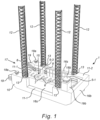
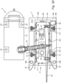
- a jack-up vessel or platform 1 in accordance with an embodiment of the invention comprises a hull 10, and a number of vertically extending legs 12 that connect to the hull 10 through jacking systems 13, provided on corners of the hull 10.
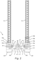
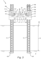
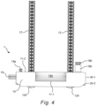
- Each jacking system 13 is configured to move a leg 12 between a higher position, shown in figures 1 , 2 and 4 , in which the leg 12 is free from an underwater bottom 2 and the hull 10 is floating on the water 30, and a lower position, shown in figures 3 and 4 .
- each leg 12 takes support on or in the underwater bottom 2 and the hull 10 is jacked out of the water over some distance 14 between a bottom of the hull 10 and the water surface 30.
- the legs 12 shown are of lattice type and at a bottom side provided with shoes or spud cans 120.
- the legs 12 may be embodied differently however, and may for instance comprise solid legs, optionally without shoes 120.
- the jack-up platform 1 further comprises a lower level deck 11-1 and a higher level deck 11-2 that together define a receiving space 15 for a barge 4.
- the receiving space 15 is confined at a bottom part by the lower level deck 11-1, at side parts by side walls 16s extending from the lower level deck 11-1 to the higher level deck 11-2, at a bow part by a bow wall 16b.
- the side walls 16s and the bow wall 16b are closed solid walls. This may be different in other embodiments, as will be illustrated further below.
- the barge 4 is suitable for carrying parts for construction of a wind turbine, such as foundation elements, tower elements, nacelles, and/or blades of such a wind turbine.
- the barge 4 may to this end be equipped with appropriate storage and fastening means for such parts.
- the jack-up platform 1 further comprises a ballasting/deballasting system, denoted in short as a (de)ballasting system (not visible), configured to bring the floating hull 10 of the jack-up platform 1 between a receiving position for the barge 4 at which the hull 10 is ballasted to a receiving draft 30-1, as shown in figure 4 , and an operational smaller draft 30-2, also shown in figure 4 .
- a ballasting/deballasting system denoted in short as a (de)ballasting system (not visible)
- the (de)ballasting system may be embodied in a manner known to one skilled in the art.
- a suitable (de)ballasting system comprises water containers integrated with the hull 10 and (de)ballasting pumps configured for pumping water in and out of said water containers. Since the containers and pumps are integrated with the hull 10 of the vessel 1, they are hidden from view by the hull 10, and therefore not visible in the figures.
- the size, amount and volume of the containers, as well as the capacity of the (de)ballasting pumps, may be selected according to engineering practice, taking into account factors like the size and weight of the barge 4 carrying the equipment or components.
- the receiving space 15 of the jack-up platform 1 further comprises a centralizing system configured to substantially centralize a received floating barge 4 in the receiving space 15, as will be elucidated further below.
- the jack-up vessel 1 combines the operation principles of both a semi-submersible vessel and a jack-up vessel.
- the jack-up vessel 1 has a higher level deck 11-2 and a lower level deck 11-1, of which the lower level deck 11-1 can be submerged by influencing the draft by the (de)ballasting system.
- a jack-up platform 1 having four legs is shown.
- the vessel 1 could also be designed to have another amount of legs.
- all figures are showing lattice truss legs 12 having a triangular cross-section in combination with a rack and pinion jacking system 13.
- the vessel 1 could also be designed with tubular legs or legs in any other shape with other jacking systems 13 in place, such as continuous or single-acting pin-in-hole systems or others.
- the main purpose of the jack-up vessel 1 is facilitating between transport and installation works, where both the actual transport and the actual installation may or will be performed by other vessels.
- the jack-up vessel 1 does not have a main crane.
- other embodiments of the jack-up vessel 1 could be equipped with an offshore crane, which would transform the jack-up vessel or platform 1 into a main installation vessel.
- the jack-up vessel 1 is capable of docking barges 4 on the lower level deck 11-1.
- a barge 4 may be permanently fixed to the lower level deck 11-1 of the jack-up platform 1, and such vessel 1 could then be used as a normal feeder jack-up, sailing back and forth to a site or a port, picking up components, avoiding the need for complex docking operations and the additional tugs that are then required.
- This embodiment provides a jack-up platform that may also be self-propelled and, optionally, equipped with a dynamic positioning (DP) system.
- thrusters 100 may be provided at an aft part of the hull 10.
- the lower level deck 11-1 could be equipped with a barge 4 carrying components that needs to be exchanged or repaired.
- the barge 4 could be loaded with a land crane for instance, in order to facilitate these maintenance works.
- the jack-up vessel 1 in another embodiment might have a couple of smaller auxiliary cranes (not shown) on board in order to transfer smaller components, such as containers and other relatively light equipment. These smaller cranes may also be certified for man-riding. Auxiliary cranes typically range between 5 and 10 tons lifting capacity but may go up to 20 tons, 30 tons or higher.
- the vessel 1 in an embodiment may be able to be steered from one or two additional control cabins 18a, located on the aft of the vessel 1 at opposite sides of the entrance opening 17. This is in addition to a control bridge 18b located at a top level of an accommodation block 19b, situated at the bow of the vessel 1.
- the vessel operators will be able to control the movements of the jack-up vessel 1 from these two additional control cabins 18a, also referred to as 'doghouses'. These will allow for good visibility over the docking operations.
- a limited amount of bunks / accommodation may be foreseen.
- a minimum amount of crew operates the vessel, whereas an additional crew may be provided in order to facilitate the barge 4 docking.
- Other accommodation may be provided for project management (like a works manager, QHSE manager, lifting supervisor), personnel of the turbine owner, personnel of a client and a Marine Warranty Surveyor, and so on.
- project management like a works manager, QHSE manager, lifting supervisor
- personnel of the turbine owner personnel of a client and a Marine Warranty Surveyor, and so on.
- no room is foreseen for a rigging crew, nor turbine technicians, since these can all be accommodated onto the main installation vessel, which normally can accommodate around 60 to 100 people, but in some cases, even well above that number.
- a walkway bridge connection or gangway may be first placed between the two vessels, in order to allow the needed personnel to walk from the main installation vessel safely onto the jack-up vessel 1 and vice versa.
- the limited requirements for the number of people on board of the invented j ack-up vessel 1 allow limiting the accommodation block 19b substantially.
- the accommodation block is situated at the bow of the vessel, stretching out completely from the port side to the starboard side, the accommodation block 19b of the jack-up vessel 1 can be reduced in size to be placed on either starboard, or port side of the vessel 1 only, as shown in figures 1-6 .
- Having a reduced accommodation block 19b on one side of the bow of the vessel 1 may limit visibility for some operations, where operators need to look from the cabin 18b to the aft of the vessel 1. Indeed the control cabin 18b on the top level of the accommodation block 19b may be situated behind one of the legs 12.
- the jack-up vessel 1 may be equipped with additional monitoring systems (not shown), such as but not limited to cameras, object detection systems and warnings.
- an aft hull 10 part of the j ack-up platform 1 comprises the opening 17 in the hull 10 for receiving the barge 4 in the receiving space 15.
- a jack-up platform 1 is provided wherein the entrance 17 of the receiving space 15 is bordered by two tapered guiding structures 19 in the form of two tapered cantilever arms, provided on each side of the entrance 17 to the receiving space 15.
- the tapered guiding structures 19 may be foreseen in order to facilitate receiving the barge 4 in the receiving space 15.
- the tapered guiding structures 19 or ⁇ catcher system' allows docking the barge 4 in higher sea states for instance.
- the jack-up vessel 1 using its optional thruster power, can hold the vessel 1 positioned relatively accurate in a horizontal plane, the barge 4 will be subject to larger horizontal motions, particularly in case it does not have built in thrusters itself and is solely steered and positioned by tugs.
- the catcher system allows docking a barge 4 having larger motions and therefore the actual width of the docking slot and/or the receiving space 15 on the jack-up vessel 1 may be kept to a minimum, which helps in keeping the jack-up vessel 1 design size as lean as possible.
- the tapered guiding ends 19, which have a receiving side wider than a receiving space 15 side facilitate the barge 4 to be guided into the relatively narrow receiving space 15 or barge dock.
- the barge dock or receiving space 15 width can be designed about equal to the maximum foreseen width of the barge 4, allowing some additional space on both sides for a fendering system in order to absorb any shock loadings into the receiving space 15 during the docking procedure and to protect the barge 4 from slamming directly into the steel wall structure (16s, 16b) while docking.
- winches may be foreseen on the jack-up platform 1 that operate mooring lines (not shown) for the barge 4, in order to help pulling it into the receiving space 15 or dock.
- the winches can either be situated at the bow of the jack-up vessel 1.
- messenger wires may run to the aft of the vessel 1 to make an easy connection when the barge 4 arrives at the entrance opening 17.
- two trolley winches may be foreseen on a rail structure extending along substantially the full length of the receiving space 15 or lower level deck 11-1.
- these winches or connection points for the mooring lines may be positioned at the aft of the vessel 1. The actual connection points may then be sliding over the rail from the aft to the bow of the vessel 1, while the barge 4 is connected. This will pull in the barge 4 into the receiving space 15 or dock.
- a messenger wire from the barge 4 could be run through the jack-up vessel 1 first.
- an additional tug could pickup this messenger wire, pull the mooring line through the jack-up vessel 1 and then pull the barge 4 onto the lower level deck 11-1 of the vessel 1 with the mooring line.
- one or more tugs may be connected as well to the mooring line in order to guide the barge 4 into the receiving space 15 from one end, while the other tug is pulling on the other end.
- the jack-up platform 1 comprises a centralizing system 5 configured to substantially centralize the received or docked barge 4 in the receiving space 15.
- the centralizing system comprises centralizing means 5 provided in the side walls 16s of the receiving space 15.
- the centralizing means can be brought from a retracted position (or retracted extension relative to the surface of each of the walls 16s) in which they may not make contact with a hull part of a docked barge 4 to a centralized position (or extended position relative to the surface of each of the walls 16s) in which a surface of the centralizing means contacts a hull part of the barge 4 with a non-zero force.
- Suitable centralizing means 5 comprise a number of inflatable fenders (5-1, 5-2, 5-3) that are provided in each side wall 16s of the receiving space 15.
- Each inflatable fender (5-1, 5-2, 5-3) in a first side wall 16s has a corresponding inflatable fender (5-1, 5-2, 5-3) in a side wall 16s opposite the first side wall 16s.
- the inflatable fenders (5-1, 5-2, 5-3) cooperate with a pressurizing pump or pumps (not shown) for inflating the inflatable fenders (5-1, 5-2, 5-3) from each deflated retracted position to each centralized position.
- each fender (5-1, 5-2, 5-3) positioned at one side wall 16s may also mutually be inflated to different degrees, if desired.
- each fender (5-1, 5-2, 5-3) is operated by its own pressurizing pump.
- the centralizing system 5 shown in the figures is configured to substantially centralize the received floating barge 4 in the middle of the receiving space 15 in a transverse direction 15-1 of the receiving space 15.
- the fenders (5-1, 5-2, 5-3) provided at each side wall 16s are arranged from bow to aft in the order fender 5-1, fender 5-2 and fender 5-3.
- the fenders (5-1, 5-2, 5-3) are embodied equal to each other, but they may also mutually differ.
- the fenders (5-1, 5-2, 5-3) are provided at some distance of each other, preferably equally distributed over the length of the side walls 16s. Obviously, the fenders (5-1, 5-2, 5-3) should be positioned such, for instance at such height relative to the lower level deck 11-1, that they may contact a hull part of the barge 4 when docked and floating (in the deballasted state of the jack-up vessel 1).
- the centralizing system 5 is able to centralize the barge 4 in a transverse direction after de-ballasting in the middle of the receiving space or dock 15. This feature is important to ensure that the center of gravity of the jack-up platform 1 and the barge 4 after docking still remains relatively close to the geometrical center of the legs 12. A slight misalignment of the barge 4 in the transverse direction of the jack-up vessel 1 may be acceptable when the vessel 1 has sufficient ballast capability in order to counteract a slight off-centered center of gravity.
- the centralizing system 5 is operational in ensuring that, in order to make jacking operations as smooth as possible, the trim and the heel angle of the jack-up vessel 1 comprising the docked barge 4 is as close to zero as possible. In this case, when the legs 12 are touching the underwater bottom 2 during the jacking operations, the legs 12 are oriented as vertically as possible within the jacking system requirements.
- the inflatable fenders or airbags (5-1, 5-2, 5-3) will be deflated. Because rubber fenders with a larger diameter as the deflated fenders (5-1, 5-2, 5-3) may be connected to the inner side walls 16s of the dock 15, the fenders (5-1, 5-2, 5-3) are protected from a potential hit of the barge 4 against the sidewalls 16s of the receiving space 15. As soon as the barge 4 is pulled in completely in the longitudinal direction of the vessel 1 and receiving space 15, the fenders or airbags (5-1, 5-2, 5-3) on the sidewalls 16s can be inflated.
- the diameter of the airbags (5-1, 5-2, 5-3) when inflated will preferably be larger than the diameter of the protective rubber fenders.
- the diameter of the airbags (5-1, 5-2, 5-3), when inflated, may be designed specifically for each different barge size, in particular its width. When inflated on both sides of the barge 4, the inflated diameters should be large enough to push against hull parts of the barge 4 at the two ends, centralizing the barge 4 in the middle of the receiving space 15 or dock in the transverse direction.
- the bottom of the receiving space 15, or the actual lower level deck 11-1 is preferably protected during the docking procedure.
- the height of the receiving space 15 and the final water level onto the lower level deck 11 of the ballasted jack-up vessel 1 may be designed in such a way that during the docking procedure the bottom of the floating barge 4 cannot bump onto the lower level deck 11-1 of the jack-up vessel 1.
- Sufficient water level under the bottom of the barge 4 is preferably foreseen in order to cope with the vertical motions of the barge 4 during the docking procedure.
- rubber floor fenders 6 are connected onto the bottom wall of the receiving space 15, i.e. the lower level deck 11-1. They are provided at some distance of each other, preferably equally distributed over the length of the receiving space 15.
- the water level on top of the lower level deck 11-1 of the jack-up vessel 1 is reduced and the bottom of the barge 4 will make contact with the lower level deck 11-1.
- De-ballasting may continue until the substantially full weight of the barge 4 is transferred onto the lower level deck 11-1 of the vessel 1.
- the lower level deck 11-1 of the receiving space 15 may comprise support elements in the form of a plurality of wooden blocks 7, next to the above mentioned rubber protection floor fenders 6. If not, the substantially complete weight of the barge 4 would be placed onto the floor fenders 6, which would entail the risk for exploding them.
- the floor fenders 6 In order for the floor fenders 6 to protect the jack-up vessel 1 and the barge 4 during the docking procedure, and in order to not explode the floor fenders 6 while de-ballasting the jack-up vessel 1, the floor fenders 6 preferably are engineered in a way that the diameter of the floor fenders 6 is larger than the height of the wooded blocks 7 if uncompressed. When the barge 4 hits the rubber floor fenders 6 during the docking procedure, the floor fenders 6 are preferably stiff enough not to be compressed until a level that the wooden blocks 7 are exposed, preventing damage to occur to these wooden blocks 7.
- the barges keel may make a first contact with the rubber floor fenders 6 provided on the lower level deck 11-1. Because the barge 4 will still have heave motions at that moment, the rubber floor fenders 6 may take up part of the loads of the barge 4 still moving up and down. This situation may be maintained until the moment the floor fenders 6 are de-compressed to a level where their diameter actually becomes smaller than the height of the wooden blocks 7. At that point in time the wooden blocks 7 take over the load of the barge 4, and the floor fenders stay decompressed. Since now substantially all the load of the barge 4 is carried by the wooden blocks 7, these wooden blocks 7 protect the floor fenders 6 from overloading and breaking.
- the inflatable fenders (5-1, 5-2, 5-3) provided at the sidewalls 16s of the receiving space 15 may be deflated, since the barge 4 is then provided in a substantially stable position relative to the receiving space 15.
- the same fender systems (5-1, 5-2, 5-3, 6) may be used in a similar way to provide for a safe and controlled undocking procedure.
- mooring lines may be again connected between the barge 4 and one or more tugs.
- the inflatable fenders (5-1, 5-2, 5-3) provided at the sidewalls 16s of the receiving space 15 may be inflated again. While ballasting, the barge 4 will at some moment lose its contact with the wooden blocks 7.
- the floor fenders 6 on the bottom of the receiving space 15 may then be decompressed to provide a larger diameter than the height of the wooden blocks 7.
- said floor fenders 6 may prevent shock loads in the first stages when the barge 4 is still floating, but the water level under the barge 4 is not sufficient yet to prevent the vertical moving barge 4 from slamming back onto the lower level deck 11-1.
- the barge 4 will finally lose contact with the floor fenders 6 and will be floating again.
- the inflatable fenders (5-1, 5-2, 5-3) may be deflated, and the mooring lines or trolley system holding the barge 4 in the longitudinal direction in position may be released. A tug is then ready to pull out the barge 4 from the receiving space 15.
- additional fendering may be foreseen in some embodiments.
- the jack-up platform 1 further comprises fenders (not shown) provided at an outer surface of the hull 10 of the vessel 1.
- fenders may comprise normal Yokohama fenders for instance. They are provided in order to protect the outer shell of the vessel 1 in case the docking procedure goes wrong and the barge 4 would bump onto the jack-up vessel 1. This external fendering is rather a protection measure and is not actually required for the docking procedure itself.
- the jack-up platform 1 may be provided with additional fenders provided at a side wall surface of the entrance 17 to the receiving space 15, preferably rolling fenders 8. They may be provided on the extended tapered outriggers 19, in the form of build-in roller fendering 8. Whenever the barge 4 would land on one of the two tapered outriggers 19, the rolling fenders 8, or fenders of any other type or combination, could act as shock absorbers, but also could have a rolling mechanism in place in order to facilitate the barge 4 being pulled into the receiving space 15 of the vessel 1.
- the jack-up platform 1 further comprises fenders provided at a side wall and/or a bow surface of the receiving space 15, preferably static rubber fenders or shock absorbers (9a, 9b). This provides further protection to the inside of the jack-up vessels dock 15, when the barge 4 is being docked.
- the barge 4 may have slight sideway motions during the docking procedure and could bump into the inner side walls 16s of the receiving space 15.
- additional rolling fenders 8 may be attached to the sidewalls 16s of the receiving dock 15 in order to facilitate guiding in the barge 4 to its final docking position.
- a trolley system is provided that on both sides is connected with mooring lines attached to the sides of the barge 4
- sideway motions of the barge 4 may be mitigated by introducing a certain amount of tension in the mooring lines provided at both sides of the barge 4. If this tension is kept during the retraction of the trolleys towards the bow of the jack-up vessel 1, sideway motions may be mitigated or reduced throughout the docking procedure and this may prevent the barge 4 from bumping into the sidewalls 16s of the receiving space 15.
- Bow rubber fendering 9b may be foreseen at the inner dock wall 16b at the bow to prevent shock loadings into the hull 10 at the moment the barge 4 is pulled completely into the receiving space 15.
- the bow rubber fenders 9b also help in centering the barge 4 in the longitudinal direction of the receiving space 15.
- winches will be present at the bow of the vessel 1 to hold the barge 4 in place in the longitudinal direction after the barge 4 is floated into the receiving space 15 but is still in a floating modus.
- the barge 4 may be positioned at a substantially centralized location, preferably against the bow fenders 9b located at the inner dock wall 16b at the bow in the longitudinal direction after de-ballasting.
- the fenders 9a provided at the side walls 16s of the receiving space 15 extend into the receiving space 15 over a distance that does not interfere with the centralizing system, comprising the inflatable fenders (5-1, 5-2, 5-3) when activated.
- the extension into the receiving space 15 of the inflatable fenders (5-1, 5-2, 5-3) in the activated state should be larger than the (substantially constant) extension of the fenders 9a provided at the side walls 16s into the receiving space 15.
- FIG. 7 and 8 another embodiment of the jack-up platform 1 is shown in a perspective and a top view, respectively.
- the vessel 1 comprises many features already disclosed in the context of the description of the embodiment shown in figures 1-6 . We incorporate the description of these features in the description of the present embodiment, in order to avoid any unnecessary repetition.
- the embodiment shown in figures 7 and 8 differs from the embodiment shown in figures 1-6 in that the hull 10 comprises one or more further openings 26s at both sides of the hull 10.
- the side walls 16s of the hull 10 of the embodiment of figures 1-6 are replaced by two openings 26s provided at both sides of the hull 10.
- the lower wall of the openings 26s is level with the bottom surface of the lower level deck 11-1.
- the side openings 26s are stiffened with a framework 27 of mutually interconnected horizontal stiffening ribs 27-1 and vertical stiffening ribs 27-2. This allows providing the hull 10 with enough stiffness and strength.
- the side openings 26s provided with the stiffening framework 27 allows water to freely enter the receiving space 15.
- the framework 27 is at a top part thereof provided with a crossing walkway 27-3.
- the framework 27 may also be provided with panels for breaking incoming waves.
- the embodiment shown in figures 9 and 10 differs from the embodiment shown in figures 1-6 in that the hull 10 comprises one further opening 26b of the hull 10 is provided at the bow of the hull 10.
- This embodiment has solid side walls 16s, as in the embodiment of figures 1-6 .
- the bow wall 16b of the hull 10 of the embodiment of figures 1-6 is replaced by an opening 26b provided at the bow of the hull 10.
- a lower wall of the bow opening 16b is level with the bottom surface of the lower level deck 11-1.
- the bow opening 16b allows water to freely enter the receiving space 15 and provides an alternative entry of exit for a barge 4 to be docked.
- the embodiment shown in figures 11 and 12 differs from the embodiment shown in figures 1-6 in that the hull 10 comprises one or further openings 26s at both sides of the hull 10, as well as one further opening 26b of the hull 10 provided at the bow of the hull 10.
- This embodiment is a combination of the embodiments shown in figures 7 , 8 , 9 and 10 , to which description we refer.
- the invented j ack-up platform 1 can advantageously be used for facilitating the placement offshore of wind turbine equipment using a main installation vessel.
- a main installation vessel may stay offshore during the installation of an offshore windfarm, and so does not need to sail back and forth to and from a port or site, installation cycles may be increased. This may allow projects to be constructed quicker as is currently the standard in the state of the art. This is made possible by using dedicated transport and installation jack-up vessels.
- a sufficient number of barges 4 may be deployed in parallel, thereby providing a continuous flow of new turbine components to install on-site. Further, the docking of the barges 4 may also be performed completely independent of the critical installation path of the main installation vessel. Indeed, there generally is sufficient time available for the invented jack-up vessel 1 to undock and dock a new barge 4, while the main installation vessel is allowed to finish up the works on a previous site or location.
- a method for facilitating the offshore installation of a wind turbine using the invented jack-up platform 1 is illustrated with reference to figures ...
- a barge 4 is positioned close or next to a load-out area, such as a port, and several wind turbine generator components, such as foundation piles or mast segments 40, one or more nacelles 41, and a number of wind turbine blades 42 are loaded onto the deck of the barge 4.
- the components (40, 41, 42) may be sea fastened by providing them in a suitable storage, such as the rack 43 shown in figure 13 for sea fastening the wind turbine blades 42.
- a tug 20 will typically tow the barge 4 from the loadout location to the offshore wind installation area, and in the vicinity of a jack-up platform 1.
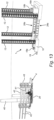
- an offshore assist tug (not shown in the figures) may be attached to a feeder barge who will assist the barge 4 and the tug 20 with the final maneuvering within the offshore windfarm and with positioning of the feeder barge next to the jack-up vessel 1, which will be waiting in a floating condition, as shown in figures 13 and 14 .
- the jack-up platform 1 may be comparable to a normal jack-up vessel which is in a floating condition.
- a normal j ack-up vessel has a main deck, of which it is not the intention to be submerged
- the jack-up vessel 1 according to the invention has a higher level deck 11-2 and a lower level deck 11-1, where it is intended to submerge the lower level deck 11-1.
- both the higher and lower level decks (11-1, 11-2) will not be submerged under water.
- the j ack-up vessel 1 has the capability of taking in a maximum amount of ballast water using pumps into its hull 10.
- the jack-up vessel 1 By activating the ballast pumps, the jack-up vessel 1 will take on more weight by the added water mass, causing the draft to increase to a second and maximum draft, or any intermediate stage draft. In practice, this means that the vessel's 1 hull 10 will be lowered deeper into the water. A sufficient amount of ballast has to be added so the lower level deck 11-1 of the vessel 1 will be submerged underwater, while the upper level deck 11-2 of the vessel 1 will stay dry and above the water level. Sufficient water column needs to be created on top of the lower level deck 11-1, such that the height of the water column is minimally, but preferably larger, than the draft of the barge 4.
- the submerging principle of the lower level deck 11-1 may be compared to the main working principle of a semi-submersible vessel.
- the j ack-up vessel 1 has a certain amount of j ack-up legs 12 that stick out vertically relatively high above the waterline. Since these legs 12 represent a significant amount of mass, the center of gravity and stability of the submerged jack-up vessel 1 at the higher draft or drafts in between the lower and higher draft, may be less favorable compared to the same vessel 1 without having the legs 12.
- the legs 12 may be preferred to lower the legs 12 as part of the ballasting process until a level where the legs 12 can however not touch the underwater bottom or seabed level, while the vessel is still floating. Lowering the legs 12 will actually lower the vertical center of gravity and may further stabilize the jack-up vessel 1, although relatively large part of the total vessel mass, including ballast water, is already situated under the waterline (30-1, 30-2).
- the whole or part of the ballasting procedure of the j ack-up platform 1 from a low draft 30-2 to a high draft 30-1 does not need to start when the barge 4 has arrived in the vicinity of the vessel 1.
- the vessel 1 could already be in a position of high draft 30-1, whenever possible, before the loaded barge 4 arrives.
- the jack-up vessel 1 indeed is able to survive in severe sea conditions when being in this high draft floating condition.
- the j ack-up vessel 1 design preferably should be such that the distance between the legs 12 in the transversal direction of the vessel 1 should at least accommodate the width of the intended barge 4.
- potential openings on the side of the jack-up platform 1 could also serve this purpose, which in the latter case requires the distance between the legs 12 in the longitudinal direction to be minimally equal to either the width of the barge 4, but preferably the length of the barge 4.
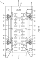
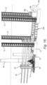
- the barge 4 is floated onto the submerged lower level deck 11-1 into a position where the bottom of the barge 4 is partly positioned right on top of the lower level deck 11-1. This step of the method is shown in figures 15 and 16 .
- the tug 20 or additional tugs may be disconnected.
- the barge 4 may then be pulled further inside the receiving space 15 by mooring lines connected to winches to a position shown in figures 17 and 18 .
- the inflatable airbags (5-1, 5-2, 5-3) provide on the side walls 16s of the receiving space 15 are then inflated to centralize the floating barge 4 and hold the barge 4 stationed on the correct horizontal position relative to the receiving space 15.
- a certain water column will be present between the top of the lower level deck 11-1 of the receiving space 15 and the bottom of the barge 4. This means that the barge is at this stage floating on top of the submerged lower level deck 11-1. No connection has been made yet between the two bodies - the receiving dock 15 and the barge 4 - in the vertical direction.
- the barge 4 may be steered by tugs and winches, but the barge 4 may also be provided with built-in thrusters, so it can maneuver partly or completely independent on its own into the receiving dock 15.
- the docking procedure is preferably carried out with the jack-up platform 1 in a floating position. Where other similar concepts are first putting their legs on to the seabed before the docking procedure starts, the invented jack-up platform preferably performs its complete docking and undocking process in a floating vessel modus.
- j ack-up legs 12 and the jacking system 13 are usually constructed in order to be loaded in a substantial vertical direction only, with limited capability of taking external horizontal loads.
- the horizontal wave loading would imply to design for a stronger and larger jacking system 13 as required for normal operations, which would increase the vessel size significantly. Further, the vessel stability needs to be guaranteed having these larger legs 12.
- the invented jack-up platform 1 preferably docks a barge 4 in a floating modus by ballasting down to a larger draft, without having its legs 12 touching the underwater bottom 2, limited or no forces at all will go into the jacking system 13 during the docking phase at the larger draft.
- the jack-up vessel 1 may further de-ballast again after taking the barge 4 to its initial and smaller draft before jacking operations will take place. This limits the amount of external horizontal forces that go into the hull 10 during the initial jacking operations when the legs 12 are touching the underwater bottom 2 and the hull 2 is still in the water. Jacking operations and the forces going into the hull 10 during the initial phase when the legs 12 are on the underwater bottom 2 but the hull 10 is still in the water may be compared to the forces experienced by a state of the art jack-up vessel.
- the j ack-op vessel 1 As the j ack-op vessel 1 is in a floating condition as well, it may be held in place by the vessel operators in a so-called joystick mode, where position keeping is done manually.
- the jack-up vessel 1 may be equipped with an automated Dynamic Positioning (DP) system, although such a DP system could act in an opposite way as desired whenever an unexpected external force comes into the system, different than normal waves.
- DP Dynamic Positioning
- the advantage of being in joystick mode during the docking procedure is that the jack-up vessel's 1 operator could make slight heading or positioning adaptations to counteract the less controllable barge 4.
- docking operations may be aborted at any time, if needed.
- these connections preferably may comprise a safe quickrelease function whenever needed, in order for the tug 20 to pull the barge 4 away from the jack-up platform 1 in case of emergency.
- the jack-up platform 1 may start up its ballast pumps in reverse in order to de-ballast the jack-up platform to a lower draft 30-2.
- the water will be pumped out of the ballast tanks situated in the hull 10 of the vessel 1, and the overall mass of the vessel 1 will be reduced. Consequently, the draft will be changed from a higher draft 30-1 back To a lower draft 30-2, or an intermediate draft in between.
- the water column on the lower level deck 11-1 will be slowly reduced until the water column has the same height as the draft of the barge 4. At that point in time, the bottom of the barge 4 and the top of the lower level deck 11-1 will make contact with each other.
- the floor fenders 6 provided on the lower level deck 11-1 will act as a shock damper when the first contact is made.
- the wooden blocks 7, also provided on the lower level deck 11-1 will act as a support basis for the barge 4, which prevents any steel-to-steel contact happening between the two vessels 1 and 4.
- the wooden blocks 7 have a relatively high coefficient of friction, which will allow that in the next phases during the transport, the barge 4 may not slight sideways easily.
- the water column on the lower level deck 11-1 of the vessel 1 will continue to reduce, until all water is removed.
- the full weight of the barge 4 and its cargo will be standing on the lower level deck 11-1 of the floating vessel 1. It is not necessary to remove all the water and in an embodiment of the method not all water needs to be removed from the lower level deck 11-1 before performing the next step.
- the jack-up platform 1 may move to its final position in order to facilitate the installation of the wind turbine components (40, 41, 42).
- This transit can be done completely on the vessel's own keel, meaning the vessel 1 is then equipped with sufficient thrusters 100 in order to sail completely on its own.
- the vessel 1 could also be towed to its next location with the help of tugs (not shown).
- tugs not shown
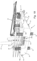
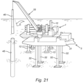
- the jack-up vessel 1 After the arrival of the jack-up vessel 1 at the final position, it may position itself using its dynamic positioning (DP) system, may put it legs 12 onto the underwater bottom 2, may pre-load the legs 12 and jack-up the hull 10, including the barge 4 with the components (40, 41, 42), out of the water, creating a fixed platform offshore. This position is shown in figures 19 and 20 .
- the final location may be located directly next to a pre-installed foundation for the wind turbine to be placed.
- tugs (not shown) could be used to bring the jack-up vessel 1 into its final position until the legs 12 are onto the underwater bottom 2 and pre-loading has been completed. It may easily be understood that in a stable position of the jack-up platform 1 with its legs 12 resting on or in the underwater bottom 2, both lower level deck 11-1 and higher level deck 11-2 are completely jacked out of the water.
- a main installation jack-up vessel 3 may have finished an installation of a wind turbine generator on a previous location, and has sailed towards the next location, where the jack-up vessel 1 will be waiting in jacked-up state.
- the main installation vessel 3 may position itself next to a pre-installed foundation 45 and next to the j ack-up vessel 1, as shown, optionally using its dynamic positioning system. Once on position, it will lower its legs 32 onto the seabed 2, perform pre-loading activities, and will jack-up its hull 31 out of the water. In some cases, the main installation vessel 3 may already have arrived before the jack-up vessel 1 is on site.
- a lifting crane 33 provided on deck of the main installation vessel 3 may be deployed to start lifting the wind turbine generator components (40, 41, 42) from the deck of the barge 4.
- the lifting crane 33 may either lift the components (40, 41, 42) on deck of the main installation vessel 3, or may directly install the components (40, 41, 42) on the pre-installed foundation 45, as shown in figure 21 .
- the jack-up platform 1, still carrying the barge 4 may jack-down again by retracting its legs 12 from the underwater bottom 2, and may sail away from the installation location, for instance to a safer location to perform a next docking cycle, as shown in figure 22 .
- the main installation vessel 3 may stay at the current location as it may have to perform at least some more finalization works to the installed wind turbine (40, 41, 42). Once ready, the main installation vessel 3 may also jack-down, retract its legs 32 and sail to a next location.
- the jack-up platform 1 in a final step of the method may proceed with the barge 4 undocking procedure, which is the same procedure as described for the docking performed in reverse order. If needed, the legs 12 can be lowered again until a level above the seabed 2 to gain stability.
- the ballast pumps are activated to pump seawater into the ballast tanks within the hull 10 of the vessel 1, thereby increasing the draft of the vessel 1 to the higher draft 30-2 at which the lower level deck 11-1 is submerged and the barge 4 is floating in the receiving space or dock 15.
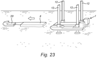
- a tug 20 may be connected to the unloaded barge 4, the winches or other connections from the barge 4 to the jack-up vessel 1 are released and the tug 20 tows the barge 4 out of the receiving space 15 and away from the jack-up vessel 1, as shown in figure 23 .
- the jack-up vessel 1 may be immobilized until a next barge 4, loaded with equipment to be installed, arrives to be docked.
- the above described docking/undocking process of the barge 4 in and out of the jack-up platform 1 may also be carried out at another location than the offshore wind farm itself. It may be carried out in the vicinity of the installation site, reasonably far from it, or even far away from the installation site of the offshore windfarm.
Landscapes
- Engineering & Computer Science (AREA)
- Mechanical Engineering (AREA)
- General Engineering & Computer Science (AREA)
- Combustion & Propulsion (AREA)
- Chemical & Material Sciences (AREA)
- Life Sciences & Earth Sciences (AREA)
- Sustainable Development (AREA)
- Sustainable Energy (AREA)
- Ocean & Marine Engineering (AREA)
- Transportation (AREA)
- Civil Engineering (AREA)
- Structural Engineering (AREA)
- Wind Motors (AREA)
Claims (17)
- Eine Hubplattform (1), die einen Rumpf (10) und eine Anzahl von Beinen (12) aufweist, die mit dem Rumpf über Hebesysteme (13) verbunden sind, die jeweils so konfiguriert sind, dass sie ein Bein zwischen einer niedrigen Position, in der das Bein auf einem Unterwasserboden (2) aufliegt und der Rumpf aus dem Wasser gehoben ist, und einer hohen Position, in der sich das Bein im Wesentlichen über das Deck erstreckt, frei vom Unterwasserboden ist und der Rumpf auf dem Wasser schwimmt, wobei die Hubplattform ferner ein höher gelegenes Deck (11-2) und ein niedriger gelegenes Deck (11-1) aufweist, die einen Aufnahmeraum (15) für einen Lastkahn (4) definieren, der optional geeignet ist, Teile für den Bau einer Windturbine zu tragen, und ferner ein (Ent-)Ballastierungssystem, das so konfiguriert ist, dass es den schwimmenden Rumpf zwischen eine Aufnahmeposition, in der der Rumpf auf einen Aufnahmetiefgang (30-1) ballastiert ist, in dem das niedriger gelegene Deck unter Wasser getaucht ist und der Lastkahn in dem Aufnahmeraum durch eine Öffnung (17) in dem Rumpf aufgenommen werden kann, und einen kleineren Betriebstiefgang (30-2), in dem im Wesentlichen kein Wasser auf dem niedriger oder dem höher gelegenen Deck fließen kann, bringt, wobei der Aufnahmeraum ferner ein Zentralisierungssystem aufweist, das so konfiguriert ist, dass es den aufgenommenen schwimmenden Lastkahn in dem Aufnahmeraum im Wesentlichen zentralisiert, dadurch gekennzeichnet, dass es ferner aufweist:
Bodenfender (6), die auf dem niedriger gelegenen Deck vorgesehen sind, vorzugsweise Gummifender, wobei das niedriger gelegene Deck des Aufnahmeraums ferner Stützelemente (7) aufweist und die Bodenfender in einem unbelasteten Zustand höher als die Stützelemente verlaufen. - Hubplattform (1) nach Anspruch 1, wobei das Zentralisierungssystem so konfiguriert ist, dass es den aufgenommenen Lastkahn (4) im Wesentlichen in der Mitte des Aufnahmeraums (15) in einer Querrichtung des Aufnahmeraums zentralisiert.
- Hubplattform (1) nach Anspruch 1 oder 2, wobei das Zentralisierungssystem Zentralisierungsmittel (5) aufweist, die in Seitenwänden (16s) des Aufnahmeraums (15) vorgesehen sind, wobei die Zentralisierungsmittel in eine Position gebracht werden können, in der eine Oberfläche davon einen Rumpfteil des Lastkahns (4) mit einer von Null verschiedenen Kraft berührt.
- Hubplattform (1) nach Anspruch 3, wobei die Zentralisierungsmittel (5) aufblasbare Fender (5-1, 5-2, 5-3) aufweisen, die mit einer Druckpumpe zum Aufblasen der aufblasbaren Fender zusammenwirken.
- Hubplattform (1) nach einem der vorhergehenden Ansprüche, wobei das (Ent)Ballastierungssystem in den Rumpf (10) integrierte Wasserbehälter und (Ent)Ballastierungspumpen aufweist, die zum Pumpen von Wasser in die und aus den Wasserbehältern konfiguriert sind.
- Hubplattform (1) nach einem der vorhergehenden Ansprüche, wobei das niedriger gelegene Deck (11-1) des Aufnahmeraums (15) Stützelemente für den Lastkahn (4), wie z. B. Holzblöcke (7), aufweist, die eine obere Stützfläche mit einem relativ hohen Reibungskoeffizienten haben.
- Hubplattform (1) nach einem der vorhergehenden Ansprüche, wobei der Eingang (17) des Aufnahmeraums (15) von zwei sich verjüngenden Führungsstrukturen (19), beispielsweise zwei sich verjüngenden Auslegerarmen, begrenzt wird, die auf jeder Seite des Eingangs (17) zum Aufnahmeraum (15) vorgesehen sind.
- Hubplattform (1) nach einem der vorhergehenden Ansprüche, die ferner Laufkatzenwinden aufweist, die auf einer Schienenstruktur vorgesehen sind, die sich im Wesentlichen über die gesamte Länge des Decks der ersten Ebene (11-1) erstreckt, wobei die Laufkatzenwinden von einer Position am Heck der Plattform zu einer Position näher am Bug der Plattform beweglich sind.
- Hubplattform (1) nach einem der vorhergehenden Ansprüche, die ferner Fender aufweist, die an einer Seitenwandfläche des Eingangs zum Aufnahmeraum vorgesehen sind, vorzugsweise Rollfender (8).
- Hubplattform (1) nach einem der vorhergehenden Ansprüche, wobei an der Seitenwand des Aufnahmeraums (15) vorgesehene Fender (9a, 9b) über einen Abstand in den Aufnahmeraum hineinragen, der das Zentralisierungssystem bei Aktivierung nicht behindert.
- Hubplattform (1) nach einem der vorhergehenden Ansprüche, die einen im Aufnahmeraum (15) aufgenommenen Lastkahn (4) aufweist.
- Eine Hubplattform (1) nach einem der vorhergehenden Ansprüche, wobei der Rumpf (10) eine oder mehrere weitere Öffnungen (26s) an einer oder beiden Seiten des Rumpfes und/oder am Bug des Rumpfes aufweist.
- Hubplattform (1) nach Anspruch 12, wobei die weiteren Öffnungen (26s) des Rumpfes (10) an beiden Seiten des Rumpfes vorgesehen sind.
- Hubplattform (1) nach einem der Ansprüche 12 bis 13, wobei die eine oder die mehreren Öffnungen (26s), vorzugsweise die seitlichen Öffnungen, mit mindestens einem Gerüst (27) aus Versteifungsrippen (27-1, 27-2), einem kreuzenden Steg (27-3) oder Platten zum Brechen ankommender Wellen versehen sind.
- Verfahren zur Erleichterung der Offshore-Installation einer Windkraftanlage, wobei das Verfahren die folgenden Schritte aufweist:- Bereitstellen einer Hubplattform (1) nach einem der vorhergehenden Ansprüche;- Ballastieren des Rumpfes (10) mit der Plattform in einer schwimmenden Position auf den Aufnahmetiefgang (30-1), bei dem das niedriger gelegene Deck (11-1) unter Wasser getaucht ist;- Aufnehmen eines Lastkahns (4), der Teile (40, 41, 42) für den Bau einer Windkraftanlage trägt, in dem Aufnahmeraum (15) durch eine Öffnung im Rumpf;- weitgehendes Zentralisieren des schwimmenden Lastkahns in dem Aufnahmeraum unter Verwendung des Zentralisierungssystems;- Entballastieren des Rumpfes mit der Plattform in einer schwimmenden Position auf den kleineren Betriebstiefgang (30-2), in dem im Wesentlichen kein Wasser auf dem niedriger und dem höher gelegenen Deck fließen kann, und der Lastkahn von dem niedriger gelegenen Deck getragen wird;- Bringen der schwimmenden Plattform in die Nähe eines Installationsortes für die Windkraftanlage, und- Bewegen der Beine (12) der Hubplattform in eine niedrigere Position, in der die Beine auf dem Unterwasserboden (2) aufliegen und der Rumpf aus dem Wasser gehoben ist.
- Verfahren nach Anspruch 15, wobei die Aufnahme des Lastkahns (4) mit der Plattform (1) in einer schwimmenden Position durchgeführt wird.
- Verfahren nach einem der Ansprüche 15 bis 16, ferner aufweisend das Anlegen eines Windkraftanlagen-Installationsschiffs (3), das einen Hebekran (13) für die Windkraftanlagen-Konstruktionsteile (40, 41, 42) neben der Hubplattform (1) aufweist.
Applications Claiming Priority (1)
| Application Number | Priority Date | Filing Date | Title |
|---|---|---|---|
| US17/083,550 US11168666B1 (en) | 2020-10-29 | 2020-10-29 | Jack-up platform with receiving space for a barge and method for offshore installation of a wind turbine |
Publications (3)
| Publication Number | Publication Date |
|---|---|
| EP3992368A1 EP3992368A1 (de) | 2022-05-04 |
| EP3992368B1 true EP3992368B1 (de) | 2024-03-06 |
| EP3992368B8 EP3992368B8 (de) | 2024-08-14 |
Family
ID=78414542
Family Applications (1)
| Application Number | Title | Priority Date | Filing Date |
|---|---|---|---|
| EP21205623.8A Active EP3992368B8 (de) | 2020-10-29 | 2021-10-29 | Hebeplattform mit aufnahmeraum für ein schiff und verfahren zur offshore-installation einer windturbine |
Country Status (4)
| Country | Link |
|---|---|
| US (1) | US11168666B1 (de) |
| EP (1) | EP3992368B8 (de) |
| ES (1) | ES2980489T3 (de) |
| PT (1) | PT3992368T (de) |
Families Citing this family (10)
| Publication number | Priority date | Publication date | Assignee | Title |
|---|---|---|---|---|
| DE102019117268B4 (de) * | 2019-06-26 | 2024-09-26 | Tractebel Overdick GmbH | Installationsanordnung mit Hubinsel und einer Barge und ein Verfahren zum Aufbau der Installationsanordnung |
| NO346384B1 (en) * | 2020-08-20 | 2022-07-04 | Fred Olsen Ocean Ltd | A method and facility for assembling a plurality of floating wind turbines |
| KR20240004955A (ko) * | 2021-05-06 | 2024-01-11 | 프리드 앤드 골드만, 엘엘씨 디/비/에이 프리드 앤드 골드만, 엘티디. | 해상 자기-엘리베이팅 선박과 함께 사용하도록 구성된 수송 선박용 랙 구조물을 위한 시스템들 및 방법들 |
| JP2025522798A (ja) * | 2022-07-01 | 2025-07-17 | プラネット フォーティトゥービー リミテッド | 構造物の組み立てにおける、およびそれに関連する改良 |
| US12338593B2 (en) * | 2022-07-21 | 2025-06-24 | Huaneng Shanxi Comprehensive Energy Co. Ltd. | Adjustable platform for installing wind turbine generator |
| CN115450848B (zh) * | 2022-09-20 | 2025-07-15 | 烟台中集来福士海洋工程有限公司 | 浮式风机的海上安装系统及海上安装方法 |
| NL2034644B1 (en) * | 2023-04-20 | 2024-10-28 | Heerema Marine Contractors Nl | A method and system for installing a wind turbine offshore and an assembly for use in combination with said method and system |
| NO347991B1 (en) * | 2023-04-24 | 2024-06-10 | Floating Maintenance Solution As | Method for installation and maintenance of floating wind turbines |
| CN118273886B (zh) * | 2024-06-03 | 2024-10-01 | 威海德创船舶技术有限公司 | 一种风电船桁架 |
| GB202414776D0 (en) * | 2024-10-08 | 2024-11-20 | Planet 42B Ltd | Method and system for deploying a structure for offshore use |
Family Cites Families (11)
| Publication number | Priority date | Publication date | Assignee | Title |
|---|---|---|---|---|
| US1533776A (en) * | 1922-06-07 | 1925-04-14 | Tiburtius Carl | Transport |
| US3973512A (en) * | 1972-10-31 | 1976-08-10 | Fahrner Willard F | Ship connecting structure |
| US4456404A (en) * | 1982-02-17 | 1984-06-26 | Atlantic Pacific Marine Corporation | Method and apparatus for positioning a working barge above a sea surface |
| NO317848B1 (no) * | 2003-01-17 | 2004-12-20 | Aker Marine Contractors As | Fremgangsmate og arrangement for installasjon og fjerning av gjenstander til havs |
| WO2006121189A1 (ja) * | 2005-05-13 | 2006-11-16 | National University Corporation Yokohama National University | 船舶搭載艇の降下揚収装置及び降下揚収方法 |
| DE102009011915B4 (de) | 2009-03-10 | 2018-02-01 | Senvion Gmbh | Verfahren und Anordnung zum Transportieren und zum Montieren von Komponenten einer Windenergieanlage sowie Montage-Plattform |
| WO2011029642A1 (en) * | 2009-09-14 | 2011-03-17 | Eide Marine Services As | Offshore equipment deploying and retrieving vessel |
| DK201170319A (en) * | 2011-06-21 | 2012-12-22 | Logima Aps | A self-propelled semi-submersible offshore wind farm installation vessel with a large crane |
| EP3473536A1 (de) * | 2017-10-23 | 2019-04-24 | Logima ApS | Selbstfahrendes offshore-installationsschiff |
| US10544015B1 (en) * | 2018-07-10 | 2020-01-28 | GeoSea N.V. | Device and method for lifting an object from a deck of a vessel subject to movements |
| DK180345B1 (en) * | 2019-04-01 | 2021-01-15 | Maersk Supply Service As | A method of securing and transferring a load between a vessel and an offshore installation and an apparatus therefor |
-
2020
- 2020-10-29 US US17/083,550 patent/US11168666B1/en not_active Expired - Fee Related
-
2021
- 2021-10-29 EP EP21205623.8A patent/EP3992368B8/de active Active
- 2021-10-29 PT PT212056238T patent/PT3992368T/pt unknown
- 2021-10-29 ES ES21205623T patent/ES2980489T3/es active Active
Also Published As
| Publication number | Publication date |
|---|---|
| US11168666B1 (en) | 2021-11-09 |
| PT3992368T (pt) | 2024-06-06 |
| EP3992368B8 (de) | 2024-08-14 |
| EP3992368A1 (de) | 2022-05-04 |
| ES2980489T3 (es) | 2024-10-01 |
Similar Documents
| Publication | Publication Date | Title |
|---|---|---|
| US11168666B1 (en) | Jack-up platform with receiving space for a barge and method for offshore installation of a wind turbine | |
| EP3820771B1 (de) | Vorrichtung und verfahren zum anheben eines objekts von einem deck eines sich bewegenden schiffs | |
| CN105314069B (zh) | 用于海上风轮机安装的双船体船 | |
| US4683832A (en) | Device and method to set and salvage structures | |
| US11136206B2 (en) | Method of securing and transferring a load between a vessel and an offshore installation and an apparatus therefor | |
| EP3947823B1 (de) | Verfahren zum sichern und übertragen einer ladung zwischen einem schiff und einer offshore-anlage und vorrichtung dafür | |
| EP3820770B1 (de) | Vorrichtung und verfahren zum anheben eines objekts von einem deck eines sich bewegenden schiffs | |
| CN110099845B (zh) | 自推进自升式船舶 | |
| JP7633228B2 (ja) | 係留システムを備えるジャッキアッププラットフォーム、および浮遊船舶を係留するための方法 | |
| US12420894B2 (en) | Systems and methods for a rack structure for a transport vessel adapted for use with an offshore self-elevating vessel | |
| WO2012039619A2 (en) | Vessel comprising a hull with a deck and a cargo area extending in a length direction of the deck | |
| GB2628869A (en) | Improvements in and relating to assembling a structure | |
| NL2031544B1 (en) | Jack-up vessel and method for the installation of elongate construction elements offshore | |
| GB2485678A (en) | Jack-up vessel system for offshore transport and handling of cargo | |
| WO2024165862A1 (en) | A stabilisation system and assembly for use in deep water offshore | |
| EP4547961A1 (de) | Verbesserungen an und im zusammenhang mit der montage einer struktur | |
| WO2025053752A1 (en) | Method of installing a monopile as foundation for an offshore wind turbine using a jack-up vessel | |
| WO2023194711A1 (en) | Improvements in and relating to assembling a structure | |
| WO2014011057A1 (en) | Method and device for transfer of a load |
Legal Events
| Date | Code | Title | Description |
|---|---|---|---|
| PUAI | Public reference made under article 153(3) epc to a published international application that has entered the european phase |
Free format text: ORIGINAL CODE: 0009012 |
|
| STAA | Information on the status of an ep patent application or granted ep patent |
Free format text: STATUS: THE APPLICATION HAS BEEN PUBLISHED |
|
| AK | Designated contracting states |
Kind code of ref document: A1 Designated state(s): AL AT BE BG CH CY CZ DE DK EE ES FI FR GB GR HR HU IE IS IT LI LT LU LV MC MK MT NL NO PL PT RO RS SE SI SK SM TR |
|
| STAA | Information on the status of an ep patent application or granted ep patent |
Free format text: STATUS: REQUEST FOR EXAMINATION WAS MADE |
|
| 17P | Request for examination filed |
Effective date: 20221101 |
|
| RBV | Designated contracting states (corrected) |
Designated state(s): AL AT BE BG CH CY CZ DE DK EE ES FI FR GB GR HR HU IE IS IT LI LT LU LV MC MK MT NL NO PL PT RO RS SE SI SK SM TR |
|
| GRAP | Despatch of communication of intention to grant a patent |
Free format text: ORIGINAL CODE: EPIDOSNIGR1 |
|
| STAA | Information on the status of an ep patent application or granted ep patent |
Free format text: STATUS: GRANT OF PATENT IS INTENDED |
|
| INTG | Intention to grant announced |
Effective date: 20230929 |
|
| GRAS | Grant fee paid |
Free format text: ORIGINAL CODE: EPIDOSNIGR3 |
|
| GRAA | (expected) grant |
Free format text: ORIGINAL CODE: 0009210 |
|
| STAA | Information on the status of an ep patent application or granted ep patent |
Free format text: STATUS: THE PATENT HAS BEEN GRANTED |
|
| AK | Designated contracting states |
Kind code of ref document: B1 Designated state(s): AL AT BE BG CH CY CZ DE DK EE ES FI FR GB GR HR HU IE IS IT LI LT LU LV MC MK MT NL NO PL PT RO RS SE SI SK SM TR |
|
| REG | Reference to a national code |
Ref country code: CH Ref legal event code: EP |
|
| REG | Reference to a national code |
Ref country code: IE Ref legal event code: FG4D |
|
| REG | Reference to a national code |
Ref country code: DE Ref legal event code: R096 Ref document number: 602021010066 Country of ref document: DE |
|
| P01 | Opt-out of the competence of the unified patent court (upc) registered |
Effective date: 20240409 |
|
| REG | Reference to a national code |
Ref country code: PT Ref legal event code: SC4A Ref document number: 3992368 Country of ref document: PT Date of ref document: 20240606 Kind code of ref document: T Free format text: AVAILABILITY OF NATIONAL TRANSLATION Effective date: 20240603 |
|
| REG | Reference to a national code |
Ref country code: LT Ref legal event code: MG9D |
|
| PG25 | Lapsed in a contracting state [announced via postgrant information from national office to epo] |
Ref country code: LT Free format text: LAPSE BECAUSE OF FAILURE TO SUBMIT A TRANSLATION OF THE DESCRIPTION OR TO PAY THE FEE WITHIN THE PRESCRIBED TIME-LIMIT Effective date: 20240306 |
|
| REG | Reference to a national code |
Ref country code: NL Ref legal event code: MP Effective date: 20240306 |
|
| PG25 | Lapsed in a contracting state [announced via postgrant information from national office to epo] |
Ref country code: GR Free format text: LAPSE BECAUSE OF FAILURE TO SUBMIT A TRANSLATION OF THE DESCRIPTION OR TO PAY THE FEE WITHIN THE PRESCRIBED TIME-LIMIT Effective date: 20240607 |
|
| REG | Reference to a national code |
Ref country code: DE Ref legal event code: R081 Ref document number: 602021010066 Country of ref document: DE Owner name: DEME OFFSHORE BE NV, BE Free format text: FORMER OWNERS: DEME OFFSHORE BE N.V., ZWIJNDRECHT, BE; FOSS MARITIME CO., SEATTLE, WA, US |
|
| PG25 | Lapsed in a contracting state [announced via postgrant information from national office to epo] |
Ref country code: HR Free format text: LAPSE BECAUSE OF FAILURE TO SUBMIT A TRANSLATION OF THE DESCRIPTION OR TO PAY THE FEE WITHIN THE PRESCRIBED TIME-LIMIT Effective date: 20240306 Ref country code: RS Free format text: LAPSE BECAUSE OF FAILURE TO SUBMIT A TRANSLATION OF THE DESCRIPTION OR TO PAY THE FEE WITHIN THE PRESCRIBED TIME-LIMIT Effective date: 20240606 |
|
| PG25 | Lapsed in a contracting state [announced via postgrant information from national office to epo] |
Ref country code: RS Free format text: LAPSE BECAUSE OF FAILURE TO SUBMIT A TRANSLATION OF THE DESCRIPTION OR TO PAY THE FEE WITHIN THE PRESCRIBED TIME-LIMIT Effective date: 20240606 Ref country code: NO Free format text: LAPSE BECAUSE OF FAILURE TO SUBMIT A TRANSLATION OF THE DESCRIPTION OR TO PAY THE FEE WITHIN THE PRESCRIBED TIME-LIMIT Effective date: 20240606 Ref country code: LT Free format text: LAPSE BECAUSE OF FAILURE TO SUBMIT A TRANSLATION OF THE DESCRIPTION OR TO PAY THE FEE WITHIN THE PRESCRIBED TIME-LIMIT Effective date: 20240306 Ref country code: HR Free format text: LAPSE BECAUSE OF FAILURE TO SUBMIT A TRANSLATION OF THE DESCRIPTION OR TO PAY THE FEE WITHIN THE PRESCRIBED TIME-LIMIT Effective date: 20240306 Ref country code: GR Free format text: LAPSE BECAUSE OF FAILURE TO SUBMIT A TRANSLATION OF THE DESCRIPTION OR TO PAY THE FEE WITHIN THE PRESCRIBED TIME-LIMIT Effective date: 20240607 Ref country code: FI Free format text: LAPSE BECAUSE OF FAILURE TO SUBMIT A TRANSLATION OF THE DESCRIPTION OR TO PAY THE FEE WITHIN THE PRESCRIBED TIME-LIMIT Effective date: 20240306 Ref country code: BG Free format text: LAPSE BECAUSE OF FAILURE TO SUBMIT A TRANSLATION OF THE DESCRIPTION OR TO PAY THE FEE WITHIN THE PRESCRIBED TIME-LIMIT Effective date: 20240306 |
|
| REG | Reference to a national code |
Ref country code: CH Ref legal event code: PK Free format text: BERICHTIGUNG B8 |
|
| RAP4 | Party data changed (patent owner data changed or rights of a patent transferred) |
Owner name: FOSS MARITIME COMPANY Owner name: DEME OFFSHORE BE NV |
|
| REG | Reference to a national code |
Ref country code: AT Ref legal event code: MK05 Ref document number: 1663621 Country of ref document: AT Kind code of ref document: T Effective date: 20240306 |
|
| PG25 | Lapsed in a contracting state [announced via postgrant information from national office to epo] |
Ref country code: SE Free format text: LAPSE BECAUSE OF FAILURE TO SUBMIT A TRANSLATION OF THE DESCRIPTION OR TO PAY THE FEE WITHIN THE PRESCRIBED TIME-LIMIT Effective date: 20240306 Ref country code: LV Free format text: LAPSE BECAUSE OF FAILURE TO SUBMIT A TRANSLATION OF THE DESCRIPTION OR TO PAY THE FEE WITHIN THE PRESCRIBED TIME-LIMIT Effective date: 20240306 |
|
| PG25 | Lapsed in a contracting state [announced via postgrant information from national office to epo] |
Ref country code: NL Free format text: LAPSE BECAUSE OF FAILURE TO SUBMIT A TRANSLATION OF THE DESCRIPTION OR TO PAY THE FEE WITHIN THE PRESCRIBED TIME-LIMIT Effective date: 20240306 |
|
| PG25 | Lapsed in a contracting state [announced via postgrant information from national office to epo] |
Ref country code: NL Free format text: LAPSE BECAUSE OF FAILURE TO SUBMIT A TRANSLATION OF THE DESCRIPTION OR TO PAY THE FEE WITHIN THE PRESCRIBED TIME-LIMIT Effective date: 20240306 |
|
| REG | Reference to a national code |
Ref country code: ES Ref legal event code: FG2A Ref document number: 2980489 Country of ref document: ES Kind code of ref document: T3 Effective date: 20241001 |
|
| PG25 | Lapsed in a contracting state [announced via postgrant information from national office to epo] |
Ref country code: IS Free format text: LAPSE BECAUSE OF FAILURE TO SUBMIT A TRANSLATION OF THE DESCRIPTION OR TO PAY THE FEE WITHIN THE PRESCRIBED TIME-LIMIT Effective date: 20240706 |
|
| PG25 | Lapsed in a contracting state [announced via postgrant information from national office to epo] |
Ref country code: SM Free format text: LAPSE BECAUSE OF FAILURE TO SUBMIT A TRANSLATION OF THE DESCRIPTION OR TO PAY THE FEE WITHIN THE PRESCRIBED TIME-LIMIT Effective date: 20240306 |
|
| PG25 | Lapsed in a contracting state [announced via postgrant information from national office to epo] |
Ref country code: CZ Free format text: LAPSE BECAUSE OF FAILURE TO SUBMIT A TRANSLATION OF THE DESCRIPTION OR TO PAY THE FEE WITHIN THE PRESCRIBED TIME-LIMIT Effective date: 20240306 Ref country code: EE Free format text: LAPSE BECAUSE OF FAILURE TO SUBMIT A TRANSLATION OF THE DESCRIPTION OR TO PAY THE FEE WITHIN THE PRESCRIBED TIME-LIMIT Effective date: 20240306 |
|
| PG25 | Lapsed in a contracting state [announced via postgrant information from national office to epo] |
Ref country code: AT Free format text: LAPSE BECAUSE OF FAILURE TO SUBMIT A TRANSLATION OF THE DESCRIPTION OR TO PAY THE FEE WITHIN THE PRESCRIBED TIME-LIMIT Effective date: 20240306 |
|
| PG25 | Lapsed in a contracting state [announced via postgrant information from national office to epo] |
Ref country code: PL Free format text: LAPSE BECAUSE OF FAILURE TO SUBMIT A TRANSLATION OF THE DESCRIPTION OR TO PAY THE FEE WITHIN THE PRESCRIBED TIME-LIMIT Effective date: 20240306 |
|
| PG25 | Lapsed in a contracting state [announced via postgrant information from national office to epo] |
Ref country code: SK Free format text: LAPSE BECAUSE OF FAILURE TO SUBMIT A TRANSLATION OF THE DESCRIPTION OR TO PAY THE FEE WITHIN THE PRESCRIBED TIME-LIMIT Effective date: 20240306 |
|
| PG25 | Lapsed in a contracting state [announced via postgrant information from national office to epo] |
Ref country code: SM Free format text: LAPSE BECAUSE OF FAILURE TO SUBMIT A TRANSLATION OF THE DESCRIPTION OR TO PAY THE FEE WITHIN THE PRESCRIBED TIME-LIMIT Effective date: 20240306 Ref country code: SK Free format text: LAPSE BECAUSE OF FAILURE TO SUBMIT A TRANSLATION OF THE DESCRIPTION OR TO PAY THE FEE WITHIN THE PRESCRIBED TIME-LIMIT Effective date: 20240306 Ref country code: RO Free format text: LAPSE BECAUSE OF FAILURE TO SUBMIT A TRANSLATION OF THE DESCRIPTION OR TO PAY THE FEE WITHIN THE PRESCRIBED TIME-LIMIT Effective date: 20240306 Ref country code: PL Free format text: LAPSE BECAUSE OF FAILURE TO SUBMIT A TRANSLATION OF THE DESCRIPTION OR TO PAY THE FEE WITHIN THE PRESCRIBED TIME-LIMIT Effective date: 20240306 Ref country code: IS Free format text: LAPSE BECAUSE OF FAILURE TO SUBMIT A TRANSLATION OF THE DESCRIPTION OR TO PAY THE FEE WITHIN THE PRESCRIBED TIME-LIMIT Effective date: 20240706 Ref country code: EE Free format text: LAPSE BECAUSE OF FAILURE TO SUBMIT A TRANSLATION OF THE DESCRIPTION OR TO PAY THE FEE WITHIN THE PRESCRIBED TIME-LIMIT Effective date: 20240306 Ref country code: CZ Free format text: LAPSE BECAUSE OF FAILURE TO SUBMIT A TRANSLATION OF THE DESCRIPTION OR TO PAY THE FEE WITHIN THE PRESCRIBED TIME-LIMIT Effective date: 20240306 Ref country code: AT Free format text: LAPSE BECAUSE OF FAILURE TO SUBMIT A TRANSLATION OF THE DESCRIPTION OR TO PAY THE FEE WITHIN THE PRESCRIBED TIME-LIMIT Effective date: 20240306 |
|
| PG25 | Lapsed in a contracting state [announced via postgrant information from national office to epo] |
Ref country code: IT Free format text: LAPSE BECAUSE OF FAILURE TO SUBMIT A TRANSLATION OF THE DESCRIPTION OR TO PAY THE FEE WITHIN THE PRESCRIBED TIME-LIMIT Effective date: 20240306 |
|
| REG | Reference to a national code |
Ref country code: DE Ref legal event code: R097 Ref document number: 602021010066 Country of ref document: DE |
|
| PG25 | Lapsed in a contracting state [announced via postgrant information from national office to epo] |
Ref country code: IT Free format text: LAPSE BECAUSE OF FAILURE TO SUBMIT A TRANSLATION OF THE DESCRIPTION OR TO PAY THE FEE WITHIN THE PRESCRIBED TIME-LIMIT Effective date: 20240306 |
|
| PLBE | No opposition filed within time limit |
Free format text: ORIGINAL CODE: 0009261 |
|
| STAA | Information on the status of an ep patent application or granted ep patent |
Free format text: STATUS: NO OPPOSITION FILED WITHIN TIME LIMIT |
|
| PG25 | Lapsed in a contracting state [announced via postgrant information from national office to epo] |
Ref country code: DK Free format text: LAPSE BECAUSE OF FAILURE TO SUBMIT A TRANSLATION OF THE DESCRIPTION OR TO PAY THE FEE WITHIN THE PRESCRIBED TIME-LIMIT Effective date: 20240306 |
|
| PG25 | Lapsed in a contracting state [announced via postgrant information from national office to epo] |
Ref country code: DK Free format text: LAPSE BECAUSE OF FAILURE TO SUBMIT A TRANSLATION OF THE DESCRIPTION OR TO PAY THE FEE WITHIN THE PRESCRIBED TIME-LIMIT Effective date: 20240306 |
|
| 26N | No opposition filed |
Effective date: 20241209 |
|
| PG25 | Lapsed in a contracting state [announced via postgrant information from national office to epo] |
Ref country code: SI Free format text: LAPSE BECAUSE OF FAILURE TO SUBMIT A TRANSLATION OF THE DESCRIPTION OR TO PAY THE FEE WITHIN THE PRESCRIBED TIME-LIMIT Effective date: 20240306 |
|
| REG | Reference to a national code |
Ref country code: DE Ref legal event code: R119 Ref document number: 602021010066 Country of ref document: DE |
|
| REG | Reference to a national code |
Ref country code: CH Ref legal event code: PL |
|
| PG25 | Lapsed in a contracting state [announced via postgrant information from national office to epo] |
Ref country code: MC Free format text: LAPSE BECAUSE OF FAILURE TO SUBMIT A TRANSLATION OF THE DESCRIPTION OR TO PAY THE FEE WITHIN THE PRESCRIBED TIME-LIMIT Effective date: 20240306 |
|
| PG25 | Lapsed in a contracting state [announced via postgrant information from national office to epo] |
Ref country code: DE Free format text: LAPSE BECAUSE OF NON-PAYMENT OF DUE FEES Effective date: 20250501 |
|
| PG25 | Lapsed in a contracting state [announced via postgrant information from national office to epo] |
Ref country code: BE Free format text: LAPSE BECAUSE OF NON-PAYMENT OF DUE FEES Effective date: 20241031 Ref country code: LU Free format text: LAPSE BECAUSE OF NON-PAYMENT OF DUE FEES Effective date: 20241029 |
|
| PG25 | Lapsed in a contracting state [announced via postgrant information from national office to epo] |
Ref country code: FR Free format text: LAPSE BECAUSE OF NON-PAYMENT OF DUE FEES Effective date: 20241031 |
|
| PG25 | Lapsed in a contracting state [announced via postgrant information from national office to epo] |
Ref country code: CH Free format text: LAPSE BECAUSE OF NON-PAYMENT OF DUE FEES Effective date: 20241031 |
|
| REG | Reference to a national code |
Ref country code: BE Ref legal event code: MM Effective date: 20241031 |
|
| PG25 | Lapsed in a contracting state [announced via postgrant information from national office to epo] |
Ref country code: PT Free format text: LAPSE BECAUSE OF NON-PAYMENT OF DUE FEES Effective date: 20250729 |
|
| PG25 | Lapsed in a contracting state [announced via postgrant information from national office to epo] |
Ref country code: IE Free format text: LAPSE BECAUSE OF NON-PAYMENT OF DUE FEES Effective date: 20241029 |
|
| REG | Reference to a national code |
Ref country code: ES Ref legal event code: FD2A Effective date: 20251126 |
|
| PG25 | Lapsed in a contracting state [announced via postgrant information from national office to epo] |
Ref country code: ES Free format text: LAPSE BECAUSE OF NON-PAYMENT OF DUE FEES Effective date: 20241030 |
|
| PG25 | Lapsed in a contracting state [announced via postgrant information from national office to epo] |
Ref country code: HU Free format text: LAPSE BECAUSE OF FAILURE TO SUBMIT A TRANSLATION OF THE DESCRIPTION OR TO PAY THE FEE WITHIN THE PRESCRIBED TIME-LIMIT; INVALID AB INITIO Effective date: 20211029 |
|
| PG25 | Lapsed in a contracting state [announced via postgrant information from national office to epo] |
Ref country code: CY Free format text: LAPSE BECAUSE OF FAILURE TO SUBMIT A TRANSLATION OF THE DESCRIPTION OR TO PAY THE FEE WITHIN THE PRESCRIBED TIME-LIMIT; INVALID AB INITIO Effective date: 20211029 |