EP3992416B1 - Échelle d'évacuation inclinée repliée - Google Patents
Échelle d'évacuation inclinée repliée Download PDFInfo
- Publication number
- EP3992416B1 EP3992416B1 EP20425045.0A EP20425045A EP3992416B1 EP 3992416 B1 EP3992416 B1 EP 3992416B1 EP 20425045 A EP20425045 A EP 20425045A EP 3992416 B1 EP3992416 B1 EP 3992416B1
- Authority
- EP
- European Patent Office
- Prior art keywords
- ladder
- agricultural vehicle
- frame
- angled
- frame member
- Prior art date
- Legal status (The legal status is an assumption and is not a legal conclusion. Google has not performed a legal analysis and makes no representation as to the accuracy of the status listed.)
- Active
Links
Images






Classifications
-
- B—PERFORMING OPERATIONS; TRANSPORTING
- B60—VEHICLES IN GENERAL
- B60R—VEHICLES, VEHICLE FITTINGS, OR VEHICLE PARTS, NOT OTHERWISE PROVIDED FOR
- B60R3/00—Arrangements of steps or ladders facilitating access to or on the vehicle, e.g. running-boards
- B60R3/02—Retractable steps or ladders, e.g. movable under shock
-
- E—FIXED CONSTRUCTIONS
- E06—DOORS, WINDOWS, SHUTTERS, OR ROLLER BLINDS IN GENERAL; LADDERS
- E06C—LADDERS
- E06C5/00—Ladders characterised by being mounted on undercarriages or vehicles Securing ladders on vehicles
- E06C5/02—Ladders characterised by being mounted on undercarriages or vehicles Securing ladders on vehicles with rigid longitudinal members
- E06C5/04—Ladders characterised by being mounted on undercarriages or vehicles Securing ladders on vehicles with rigid longitudinal members capable of being elevated or extended ; Fastening means during transport, e.g. mechanical, hydraulic
-
- A—HUMAN NECESSITIES
- A01—AGRICULTURE; FORESTRY; ANIMAL HUSBANDRY; HUNTING; TRAPPING; FISHING
- A01D—HARVESTING; MOWING
- A01D41/00—Combines, i.e. harvesters or mowers combined with threshing devices
- A01D41/12—Details of combines
- A01D41/1261—Access devices for personnel
Definitions
- Agricultural vehicles span a wide range of purposes.
- Agricultural vehicles may include without limitation, sprayers, tractors, seeders, harvesters, and implements.
- Agricultural vehicles share roadways with other vehicles, and at times, roadways can be narrow especially in Europe.
- operators desire to have as much space in the cab as possible for controls, visibility, and comfort. Further, to obtain access into the cab and egress out of the cab, ladders may be utilized.
- Agricultural vehicle ladders are often positioned in awkward locations as manufacturers balance the size, namely the width, cab location, and ingress and egress from the cab with ladders. Some ladders may be vertical relative to the frame in a deployed state, which may cause an inconvenient way for an operator to reach the ground. Further, some ladders when stowed are also in a vertical position and may cover the cab door. This may impede visibility and again causes an inconvenient way to enter and exit the cab. There is a need in the art to develop an agricultural vehicle ladder that provides for convenient ingress and egress to and from the cab, maintains cab visibility, and provides an acceptable dimension of the agricultural vehicle to travel narrow roadways.
- US 6,029,775 A describes an access device for providing access between a substrate surface and the elevated side entry of a vehicle, said device comprising: i) an actuator having a rotary shaft which is rotatable about an axis between a first position and a second position; ii) a triangular platform having, first, second and third sides, the first side being attached to said shaft; iii) a ladder having a first end rigidly attached to said second side of the platform so that the ladder extends at a fixed angle to said second side, and iv) means for mounting said actuator to a vehicle having an elevated side entry whereby when said shaft is rotated between said first and second positions, the platform and ladder are swung between an access position wherein the third side of the platform extends on one side of said axis toward the entry and the ladder extends downward from the actuator and a storage position wherein the third side of the platform extends away on the opposite of said axis away from the entry and the ladder extends upwards from the actuator.
- US 2013/0092474 A1 relates to a ladder assembly for equipment, the ladder assembly comprising a ladder pivotally mounted to a mount; an actuation mechanism that includes a drive that engages a rotational actuator, the rotational actuator operatively connected to the ladder; wherein the drive causes rotation of the rotational actuator causing the ladder to pivot about the mount.
- FIGURES 1A and 1B illustrate an agricultural vehicle 100, which may comprise a frame 102.
- the frame may have a fore portion 104 towards the front of agricultural vehicle 100.
- the frame may also have an aft portion 106 towards the rear of the agricultural vehicle 100.
- the agricultural vehicle 100 may be a sprayer 108.
- the sprayer 108 may be a self-propelled sprayer. It should be understood that the agricultural vehicle 100 may include without limitation, sprayers, tractors, seeders, harvesters, and implements.
- the agricultural vehicle 100 may further comprise a boom at the aft 106. Wheels 111 are operably connected to the frame 102.
- the agricultural vehicle 100 may also comprise an operation station or cab 112 for the vehicle operator.
- the cab 112 may be disposed towards the fore portion 104 of the frame 102. In other implementations, it may be disposed about a center portion of the frame 102. The cab 112 may be positioned above the level of the wheels 111. Because the cab 112 is elevated and may be in a forward position, the operator is provided with an unobstructed view down and forward of the agricultural vehicle 100. This configuration may also provide for a larger cab space for the operator.
- the cab 112 may further comprise a cab opening 114 that may be selectably covered or sealed with a cab door 116. The cab door 116 may provide ingress and egress access from the inside of the cab 112.
- the agricultural vehicle may further comprise a platform 118.
- the platform 118 may be operably connected to the frame 102 at a rear section 122 of platform 118.
- the platform 118 may comprise a generally horizontal support surface 120 to support an operator and be elevated above an underlying surface.
- the platform 118 may be supported on an underside by the frame 12 of the machine.
- the platform 118 may extend laterally outwardly from a side of the cab 112 where the cab door 116 is located.
- the platform 118 may have lateral edges 124 about its perimeter.
- a fence 126 may extend upwardly about at least a portion of the perimeter of the platform 118.
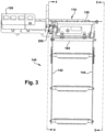
- a ladder 140 is shown.
- the ladder 140 may be operably connected to the frame 102.
- the ladder 140 may be operably connected to the platform 118, which may be operably connected to the frame 102.
- the ladder 140 may comprise a first frame member 142 and a second frame member 144.
- the first frame member 142 may have an upper portion 146 and a lower portion 148.
- the second frame member 144 may comprise an upper portion 150 and a lower portion 152.
- the upper portions 146, 150 of the first frame member 142 and the second frame member 144 may be operably coupled to the frame 102.
- the upper portions 146, 150 of the first frame member 142 and the second frame member 144 may be operably coupled to the frame 102, and by extension operably coupled to the platform 118.
- One or more foot support bodies 154 may be operably connected to the first frame member 142 and the second frame member 144. In one implementation, there may be one foot support body 154. In another implementation there may be two foot support bodies 154. In yet another implementation, there may be three foot support bodies interconnected between the first frame member 142 and the second frame member 144.
- the foot support body 154 may take any form chosen with sound engineering judgment including without limitation, a step, a rung, a plank, or other supportive body to support an operator's foot as they climb up or down the ladder 140.
- the ladder 140 may comprise a deployed position as shown in FIGURES 1B and 2-7 . Further, the ladder may have an angled stowed position as shown in FIGURES 1A and 8-13 .
- the angled stowed position may comprise the first and the second frame members 142, 144 being upward and rearward towards the aft 106 of the agricultural vehicle frame 102.
- the angled stowed position may comprise the lower portions 148, 152 of the first and the second frame members 142, 144 being upward and rearward towards the aft 106 of the agricultural vehicle frame 102.
- the ladder 140 may also comprise one or more handles to support the operator. In one implementation, there may be a first handle 156 extending from the first frame member 142.
- a second handle 157 may extend from the second frame member 144.
- a third handle 158 may be provided that may be attached to an area of the frame 102.
- the third handle may be operably connected to the platform 118.
- One or more of the handles 156, 157, 158 may optionally be rotatable to be stowed in closer proximation to the first frame member 142, or the second frame member 144 for storage to provide for a more compact angled stowed position for the ladder 140.
- the ladder 140 may comprise an angled hinge point 160, which is illustrated in FIGURES 9 , 13 , 17 , and 19 .
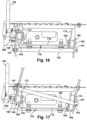
- the ladder 140 comprises a first pivot point 162 interconnecting the first frame member 142 and the agricultural vehicle frame 102 and further comprises a second pivot point 164 interconnecting the second frame member 144 and the agricultural vehicle frame 102.
- the first pivot point 162 is at a different axis than the second pivot point 164 when the ladder 140 is in the angled stowed position.
- the angled hinge point 160 may be measured between a horizontal axis H-H to the first frame member 142.
- the angled hinge point 160 may comprise an angle of about 50 degrees to about 85 degrees measured from a horizontal axis to the first frame member 142 in the stowed position.
- the angle formed between horizontal axis H-H and the first frame member 142 may be about 75 degrees.
- the ladder 140 in the angled stowed position does not materially impede ingress or egress of the cab opening 114. It should be understood that the angle formed between the horizontal axis H-H and the first frame member 142 may be any angle chosen with sound engineering judgment if it does not materially impede ingress into our egress out of the cab opening.
- first pivot point 162 and the second pivot point 164 may comprise a first rotational body 166 and a second rotational body 168, respectively.
- bushings, bearings, or any other member or device may be utilized to provide or assist rotational movement between the ladder 140 and the frame 102.
- the ladder 140 is illustrated in one exemplary embodiment in the deployed position.
- a first linkage 170 may be operably connected to the frame 102 in one implementation.
- the first linkage by be operable connected to the platform 118.
- the first linkage may comprise a first member 172, a second member 174, and an interconnecting member 176.
- first rotational body 166 and the second rotational body 168 may be operably connected to the frame 102 such as by welding or other attachment.
- the first rotational body 166 and the second rotational body 168 may be disposed adjacent to the first member 172 and to the second member 174 of the first linkage 170 respectively.
- the ladder 150 may further comprise a stop bar 182 operably connected between the first frame member 142 and the second frame member 144.
- the stop bar 182 may be operably connected to the first attachment portion 147 and the second attachment member 151.
- the stop bar 182 may be configured to provide a rigid member to stop the ladder 140 from rotating beyond a desired angle in the deployed position.
- the stop bar 182 may contact any one of a number of components of the frame 102 and/or the platform 118 to achieve the desire deployed position, such as 30 degrees from the vertical axis, for example.
- the first frame member 142 may comprise a first attachment portion 147.
- the second frame member 144 may comprise a second attachment portion 151.
- the first attachment portion 147 may be disposed adjacent the first pivot point 162, such as the first rotational body 166, and then be secured by a first pin 178.
- the second attachment portion 151 may be disposed adjacent the second pivot point 164, such as the second rotational body 168, and then be secured by a second pin 180. Because, in accordance with claim 1, the first pivot point 162 and the second pivot point 164 are on different axes, the first pivot point 162 is misaligned relative to the second pivot point 164. In this example implementation, this enables the ladder 140 to rotate about the first pivot point 162 and the second pivot point 164 from the non-angled deployed position in FIGURES 16 and 18 to the angled stowed position, illustrated in FIGURES 17 and 19 .
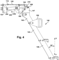
- the ladder 140 is shown in a deployed position.
- the ladder 140 may form an angle with a vertical axis V-V.
- the angle may be measured between the vertical axis V-V and the first frame member 142.
- the angle from the vertical axis V-V to the deployed ladder 140 being between about zero degrees to about forty degrees.
- the angle from the vertical axis V-V to the deployed ladder 140 may be between about 20 degrees to about 35 degrees.
- the angle between axis V-V and the deployed ladder 140 may have an angle resembling that of a stair case so that the operator may experience a natural climbing effect.
- the angle between the ladder 140 in the deployed position may an angle from the vertical axis V-V to the deployed ladder may be about 30 degrees.
- the ladder 140 may further comprise an actuator 200 for moving the ladder 140 between the deployed position and the angled stowed position.
- the actuator 200 may further comprise a hydraulic cylinder 202 having a first end 204 and a distal second end 206.
- the hydraulic cylinder may be a double acting hydraulic cylinder.
- a cylindrical body 208 may comprise the first end 204.
- a rod 210 may comprise the second distal end 206.
- the first end 204 may be operably coupled to the agricultural vehicle frame 102.
- the distal second end 206 may be operably coupled to the first frame member 142.
- the distal second end 206 may be operably coupled to the first attachment portion 147 of the first frame member 142.
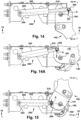
- the rod 210 is in its most fully extended position so that the ladder 140 is in the deployed position.
- the ladder 140 is in an intermediary position in FIGURE 14A where the rod 210 is only partially deployed.
- the rod 210 is in a retracted position so that the ladder 140 is in the angled stowed position.
- the hydraulic cylinder 202 may comprise a virtual lever arm shown by arrow A in the deployed position of FIGURE 14 , angled stowed position of FIGURE 15 , and in the intermediary position of FIGURE 14A .
- the virtual lever arm may be maintained on top of the angled hinge point 160, such as for example, the first pivot point 162, to optimize force requirements during deployment and stowing of the ladder 140.
- the rod 210 may be in the retracted position and the virtual lever arm may be the smallest.
- the rod 210 exerts a force against the upper attachment portion 147 of the first frame member 142 resulting in a larger virtual lever arm above the angled hinge point 160.
- the rod 210 is in the fully deployed position and the virtual lever arm is larger than in the angled stowed position, but smaller than when the rod 210 is actively deploying the ladder 140.
- the configuration of the virtual lever arm may prevent the ladder 140 from becoming immovable from the stowed position.
- the configuration of the hydraulic cylinder 202 may result in lower forces needed to deploy and stow the ladder 140 so that the hydraulic cylinder 202 the may be optimized for cost benefit.
- the ladder 140 may be configured to move manually by the operator between the angled stowed position and the deployed position as well as from the deployed position to the angled stowed position. In another implementation, the ladder 140 may be configured to be automatically moved between the angled stowed position and the deployed position as well as from the deployed position to the angled stowed position.
- the agricultural vehicle 100 may comprise a controller (not shown). The operator may have controls in the cab 112 in the form of a push button, for example. Upon activation of the controls, a signal is sent to the controller to activate the actuator 200, such as the hydraulic cylinder 202.
- the actuator 200 may then exert force on the ladder 140 to either deploy the ladder 140 or exert a force to pull on the ladder 140 to place it in the angled stowed position.
- the ladder 140 may be automatically moved to the angled stowed position upon movement of the agricultural vehicle. For example, if the ladder 140 is in the deployed position or a semi-deployed position and the agricultural vehicle 100 begins to move, the controller may send a signal to the actuator 200 to exert force on the ladder 140 to position the ladder in the angled stowed position.
- FIG. 140 another example implementation of the ladder 140 illustrates a locking arm 220 having a cavity 222 at a distal end may operably engage with an extension member 224 on the ladder 140 to maintain the ladder 140 in the angled stowed position.
- a first end 226 of the locking arm 220 may be operatively couple to the frame 102 or the platform 118.
- the extension member 224 may be disposed on the first frame member 142 of the ladder 140.
- the extension member 224 may be any body chosen in accordance with sound engineering judgment to engage with the cavity 222 of the locking arm.
- the extension member may be a fastener, a knob, a bolt head, a pin, or other similar body.
- a method for narrowly stowing the ladder 140 for the agricultural vehicle 100 between a deployed position and a stowed position is now described.
- the method may comprise the step of actuating the ladder 140 as previously described.
- the ladder 140 may be moved from a deployed position to an angled stowed position.
- the ladder 140 may comprise the angled hinge point 160, wherein the angled stowed position may comprise the first frame member 142 and the second frame member 144, which may be upward and rearward towards the aft portion 106 of the agricultural vehicle frame 102.
- the ladder 140 may rotate about the first pivot point 162 and the second pivot point 164.
- first pivot point 162 and the second pivot point are on different axes, rotation about pivot points 162, 164 results in the ladder 140 being stowed in an angled position and then deployed in a straight position as shown in the accompanying FIGURES.
- first lower portion 148 of the first frame member 142 and the second lower portion 152 of the second frame member 144 may be upward and rearward towards the aft portion 106 of the agricultural vehicle frame 102.
- the ladder 140 may be secured in the angled stowed position.
- the ladder 140 may be stowed in the angled position such that it does not materially impede egress from or entrance to a cab of the agricultural vehicle 100.
- the step of actuating the ladder 140 may comprise sensing movement of the agricultural vehicle 100. At such time, the actuator 200 may act automatically move the ladder 140 from the deployed position to the angled stowed position.
- the agricultural vehicle 100 may further comprise the hydraulic cylinder 202 operably connected between the frame 102 and the first frame member 142 of the ladder 140.
- the hydraulic cylinder 202 may comprise a virtual lever arm in the deployed position, the angled stowed position and an intermediary portion.
- the virtual level arm may be positioned above the angled hinge point 160 at all positions.
- the method may comprise the step preventing the ladder from becoming stuck or immovable in the angled stowed position.
- the actuator 200 such as the hydraulic cylinder 202 exerts force through the rod 210 against the ladder 140.
- the virtual lever arm exerts enough force to move the ladder 140 from the angled stowed position to the deployed position.
- the agricultural vehicle may be constructed narrower, which may be desired for traveling narrow roadways. Further, it prevents awkward body positioning as operators enter and leave the cab 112. It also enables for a larger cab 112 and may provide greater visibility for the operator. Operators also find ergonomic use of the ladder 140 in the deployed position because it may be angled like stairs so that operators may feel a natural climb and descent when in use.
- exemplary is used herein to mean serving as an example, instance or illustration. Any aspect or design described herein as “exemplary” is not necessarily to be construed as advantageous over other aspects or designs. Rather, use of the word exemplary is intended to present concepts in a concrete fashion.
- the term “or” is intended to mean an inclusive “or” rather than an exclusive “or.” That is, unless specified otherwise, or clear from context, "X employs A or B” is intended to mean any of the natural inclusive permutations. That is, if X employs A; X employs B; or X employs both A and B, then "X employs A or B" is satisfied under any of the foregoing instances.
- At least one of A and B and/or the like generally means A or B or both A and B.
- the articles “a” and “an” as used in this application and the appended claims may generally be construed to mean “one or more” unless specified otherwise or clear from context to be directed to a singular form.
Landscapes
- Engineering & Computer Science (AREA)
- Mechanical Engineering (AREA)
- Life Sciences & Earth Sciences (AREA)
- Environmental Sciences (AREA)
- Vehicle Step Arrangements And Article Storage (AREA)
- Ladders (AREA)
Claims (14)
- Véhicule agricole (100) comprenant une échelle (140), l'échelle comprenant :un premier membre de cadre (142) et un deuxième membre de cadre (144) chaque membre de cadre (142, 144) ayant une partie supérieure (146, 150) et une partie inférieure (148, 152) ;au moins un corps de support de pieds (154) raccordé de manière opérationnelle aux membres de cadre (142, 144) ;la partie supérieure de chaque membre de cadre (146, 150) étant raccordée de manière opérationnelle à un châssis (102) du véhicule agricole (100), le châssis du véhicule agricole comprenant un avant (104) et un arrière (106) ; etl'échelle (140) comprenant une position déployée et une position arrimée à angle, dans lequel la position arrimée à angle comprend le premier membre de cadre (144) étant vers le haut et en arrière vers l'arrière (106) du châssis (102) du véhicule agricole,dans lequel l'échelle comprend en outre un premier point de pivotement (162) et un deuxième point de pivotement (164), le premier point de pivotement (162) interconnectant le premier membre de cadre (142) et le châssis (102) du véhicule agricole, le deuxième point de pivotement (164) interconnectant le deuxième membre de cadre (144) et le châssis (102) du véhicule agricole,caractérisé en ce que :
le premier point de pivotement (162) est sur un axe différent du deuxième point de pivotement (164) de sorte que le premier point de pivotement (162) est désaligné par rapport au deuxième point de pivotement (164). - Véhicule agricole selon la revendication 1, dans lequel l'échelle comprend un point d'articulation à angle (160) configuré pour disposer l'échelle (140) dans la position arrimée à angle.
- Véhicule agricole selon la revendication 2, dans lequel le point d'articulation à angle (160) comprend un angle d'environ 50 degrés à environ 85 degrés mesuré depuis un axe horizontal au premier membre de cadre (142) dans la position arrimée.
- Véhicule agricole selon la revendication 3, dans lequel le point d'articulation à angle (160) comprend un angle d'environ 75 degrés.
- Véhicule agricole selon l'une quelconque des revendications 1 à 4, où le véhicule agricole (100) comprend en outre une cabine (112) disposée vers l'avant (104) du châssis du véhicule agricole, la cabine (112) ayant une ouverture d'entrée et de sortie (114), dans lequel l'échelle dans la position arrimée n'entrave pas l'entrée ou la sortie de l'ouverture.
- Véhicule agricole selon l'une quelconque des revendications 1 à 5, dans lequel le corps de support de pieds (154) comprend au moins l'un d'entre un échelon, une marche ou un barreau.
- Véhicule agricole selon l'une quelconque des revendications 1 à 6, dans lequel l'échelle dans la position déployée comprend un angle depuis un axe vertical à l'échelle déployée étant d'entre environ zéro degré à environ quarante degrés.
- Véhicule agricole selon la revendication 7, dans lequel l'échelle dans la position déployée comprend un angle depuis l'axe vertical à l'échelle déployée étant d'entre environ vingt degrés à environ 35 degrés.
- Véhicule agricole selon la revendication 8, dans lequel l'échelle dans la position déployée comprend un angle depuis l'axe vertical à l'échelle déployée étant d'environ 30 degrés.
- Véhicule agricole selon la revendication 1, comprenant en outre une cabine (112) raccordée de manière opérationnelle au châssis (102) du véhicule agricole, dans lequel la position arrimée à angle est configurée pour ne pas entraver une ouverture (114) à la cabine (112).
- Véhicule agricole selon l'une quelconque des revendications 1 à 10, dans lequel l'échelle est configurée pour se déplacer automatiquement à la position arrimée à angle lors du mouvement du véhicule agricole (100).
- Véhicule agricole selon l'une quelconque des revendications 1 à 11, comprenant en outre un actionneur (200) pour déplacer l'échelle entre la position déployée et la position arrimée à angle.
- Véhicule agricole selon la revendication 12, dans lequel l'actionneur (200) comprend en outre un cylindre hydraulique (202) ayant une première extrémité (204) et une deuxième extrémité distale (206), la première extrémité étant couplée de manière opérationnelle au châssis (102) du véhicule agricole et la deuxième extrémité distale étant couplée de manière opérationnelle à une partie supérieure du premier membre de cadre (142), le cylindre hydraulique comprenant un bras de levier virtuel dans la position déployée, dans la position arrimée à angle et dans une position intermédiaire, le bras de levier virtuel étant configuré pour empêcher l'échelle de devenir immuable de la position arrimée.
- Véhicule agricole selon la revendication 1, où le véhicule agricole comprend en outre une cabine (112) raccordée de manière opérationnelle au châssis (102) du véhicule agricole, et le véhicule agricole comprend en outre une plate-forme (118) raccordée de manière opérationnelle au châssis (102) du véhicule agricole et adjacente à la cabine, dans lequel l'échelle est raccordée de manière opérationnelle à la plate-forme (118).
Priority Applications (4)
| Application Number | Priority Date | Filing Date | Title |
|---|---|---|---|
| EP20425045.0A EP3992416B1 (fr) | 2020-10-30 | 2020-10-30 | Échelle d'évacuation inclinée repliée |
| AU2021240170A AU2021240170A1 (en) | 2020-10-30 | 2021-09-29 | Angle folded egress ladder |
| US17/488,694 US12214748B2 (en) | 2020-10-30 | 2021-09-29 | Angle folded egress ladder |
| BR102021019757-9A BR102021019757A2 (pt) | 2020-10-30 | 2021-10-01 | Escada para um veículo agrícola |
Applications Claiming Priority (1)
| Application Number | Priority Date | Filing Date | Title |
|---|---|---|---|
| EP20425045.0A EP3992416B1 (fr) | 2020-10-30 | 2020-10-30 | Échelle d'évacuation inclinée repliée |
Publications (2)
| Publication Number | Publication Date |
|---|---|
| EP3992416A1 EP3992416A1 (fr) | 2022-05-04 |
| EP3992416B1 true EP3992416B1 (fr) | 2023-11-01 |
Family
ID=73598027
Family Applications (1)
| Application Number | Title | Priority Date | Filing Date |
|---|---|---|---|
| EP20425045.0A Active EP3992416B1 (fr) | 2020-10-30 | 2020-10-30 | Échelle d'évacuation inclinée repliée |
Country Status (4)
| Country | Link |
|---|---|
| US (1) | US12214748B2 (fr) |
| EP (1) | EP3992416B1 (fr) |
| AU (1) | AU2021240170A1 (fr) |
| BR (1) | BR102021019757A2 (fr) |
Family Cites Families (5)
| Publication number | Priority date | Publication date | Assignee | Title |
|---|---|---|---|---|
| US6073396A (en) * | 1996-03-28 | 2000-06-13 | Kietzmann; Rudolph | Gate hinge |
| AUPP175198A0 (en) * | 1998-02-10 | 1998-03-05 | Justoy Pty Ltd | Access device |
| CA2613099C (fr) * | 2005-06-16 | 2014-05-20 | Barjoh Pty Ltd | Systeme d'acces de vehicule |
| US20130092474A1 (en) * | 2011-10-12 | 2013-04-18 | Michael William Magnussen | Ladder assembly for equipment |
| US10099622B2 (en) * | 2013-07-31 | 2018-10-16 | Oshkosh Corporation | Step assembly for a fire truck |
-
2020
- 2020-10-30 EP EP20425045.0A patent/EP3992416B1/fr active Active
-
2021
- 2021-09-29 AU AU2021240170A patent/AU2021240170A1/en active Pending
- 2021-09-29 US US17/488,694 patent/US12214748B2/en active Active
- 2021-10-01 BR BR102021019757-9A patent/BR102021019757A2/pt unknown
Also Published As
| Publication number | Publication date |
|---|---|
| AU2021240170A1 (en) | 2022-05-19 |
| US20220134958A1 (en) | 2022-05-05 |
| BR102021019757A2 (pt) | 2022-05-17 |
| EP3992416A1 (fr) | 2022-05-04 |
| US12214748B2 (en) | 2025-02-04 |
Similar Documents
| Publication | Publication Date | Title |
|---|---|---|
| US5284349A (en) | Cab step assembly | |
| US7905324B2 (en) | Access system for a moveable vehicle | |
| US6068277A (en) | Access platform system for earth-moving machinery | |
| US7055839B2 (en) | Retractable vehicle step | |
| US8016345B1 (en) | Operator cab having inwardly folding access door | |
| CA2631691C (fr) | Dispositif d'acces | |
| US5813494A (en) | Access ladder assembly for an off-highway machine | |
| RS64220B1 (sr) | Rotacioni telehendler sa višestrukim putevima za uspinjanje i spuštanje | |
| US20220048424A1 (en) | Retractable handrail arrangement | |
| AU2008252032B2 (en) | Collapsible Stairway | |
| US6659709B1 (en) | Tool carrier attachment for excavator | |
| US12214748B2 (en) | Angle folded egress ladder | |
| US6550560B2 (en) | Control handle pivot apparatus | |
| US20220332253A1 (en) | Truck mounted folding step and ladder | |
| US7585016B2 (en) | Construction machine having top door for improved ingress/egress | |
| JP2002053072A (ja) | 作業機の機体構造 | |
| EP2725141B1 (fr) | Membre articulé comportant un outil de traitement de parois et véhicule de traitement de parois d'un ouvrage | |
| EP0692182B1 (fr) | Dispositif d'accès pour moissonneuse agricole | |
| DE4330001A1 (de) | Heckträger zum Transport sperriger Lasten auf einem Kraftwagen | |
| JP3921405B2 (ja) | 高所作業車 | |
| JP7441394B2 (ja) | 薬液散布車両 | |
| FR2851527A1 (fr) | Vehicule a moteur equipe d'un marchepied escamotable | |
| EP2605633B1 (fr) | Agencement de panneaux destiné à une machine de récolte | |
| CN100554038C (zh) | 可移动车辆的进入系统 | |
| RU2789186C1 (ru) | Поворотный телескопический погрузчик с несколькими маршрутами для подъема и спуска |
Legal Events
| Date | Code | Title | Description |
|---|---|---|---|
| PUAI | Public reference made under article 153(3) epc to a published international application that has entered the european phase |
Free format text: ORIGINAL CODE: 0009012 |
|
| STAA | Information on the status of an ep patent application or granted ep patent |
Free format text: STATUS: THE APPLICATION HAS BEEN PUBLISHED |
|
| AK | Designated contracting states |
Kind code of ref document: A1 Designated state(s): AL AT BE BG CH CY CZ DE DK EE ES FI FR GB GR HR HU IE IS IT LI LT LU LV MC MK MT NL NO PL PT RO RS SE SI SK SM TR |
|
| RIN1 | Information on inventor provided before grant (corrected) |
Inventor name: PANTANO, STEFANO Inventor name: JORDAN, DANIEL C. Inventor name: FAUSCH, JOSHUA J. Inventor name: WUBBEN, THOMAS M. |
|
| STAA | Information on the status of an ep patent application or granted ep patent |
Free format text: STATUS: REQUEST FOR EXAMINATION WAS MADE |
|
| 17P | Request for examination filed |
Effective date: 20221104 |
|
| RBV | Designated contracting states (corrected) |
Designated state(s): AL AT BE BG CH CY CZ DE DK EE ES FI FR GB GR HR HU IE IS IT LI LT LU LV MC MK MT NL NO PL PT RO RS SE SI SK SM TR |
|
| GRAP | Despatch of communication of intention to grant a patent |
Free format text: ORIGINAL CODE: EPIDOSNIGR1 |
|
| STAA | Information on the status of an ep patent application or granted ep patent |
Free format text: STATUS: GRANT OF PATENT IS INTENDED |
|
| INTG | Intention to grant announced |
Effective date: 20230322 |
|
| GRAJ | Information related to disapproval of communication of intention to grant by the applicant or resumption of examination proceedings by the epo deleted |
Free format text: ORIGINAL CODE: EPIDOSDIGR1 |
|
| STAA | Information on the status of an ep patent application or granted ep patent |
Free format text: STATUS: REQUEST FOR EXAMINATION WAS MADE |
|
| GRAP | Despatch of communication of intention to grant a patent |
Free format text: ORIGINAL CODE: EPIDOSNIGR1 |
|
| STAA | Information on the status of an ep patent application or granted ep patent |
Free format text: STATUS: GRANT OF PATENT IS INTENDED |
|
| INTC | Intention to grant announced (deleted) | ||
| INTG | Intention to grant announced |
Effective date: 20230525 |
|
| GRAS | Grant fee paid |
Free format text: ORIGINAL CODE: EPIDOSNIGR3 |
|
| GRAA | (expected) grant |
Free format text: ORIGINAL CODE: 0009210 |
|
| STAA | Information on the status of an ep patent application or granted ep patent |
Free format text: STATUS: THE PATENT HAS BEEN GRANTED |
|
| AK | Designated contracting states |
Kind code of ref document: B1 Designated state(s): AL AT BE BG CH CY CZ DE DK EE ES FI FR GB GR HR HU IE IS IT LI LT LU LV MC MK MT NL NO PL PT RO RS SE SI SK SM TR |
|
| REG | Reference to a national code |
Ref country code: GB Ref legal event code: FG4D |
|
| REG | Reference to a national code |
Ref country code: CH Ref legal event code: EP |
|
| REG | Reference to a national code |
Ref country code: IE Ref legal event code: FG4D |
|
| REG | Reference to a national code |
Ref country code: DE Ref legal event code: R096 Ref document number: 602020020208 Country of ref document: DE |
|
| P01 | Opt-out of the competence of the unified patent court (upc) registered |
Effective date: 20231031 |
|
| REG | Reference to a national code |
Ref country code: NL Ref legal event code: FP |
|
| REG | Reference to a national code |
Ref country code: LT Ref legal event code: MG9D |
|
| PG25 | Lapsed in a contracting state [announced via postgrant information from national office to epo] |
Ref country code: GR Free format text: LAPSE BECAUSE OF FAILURE TO SUBMIT A TRANSLATION OF THE DESCRIPTION OR TO PAY THE FEE WITHIN THE PRESCRIBED TIME-LIMIT Effective date: 20240202 |
|
| PG25 | Lapsed in a contracting state [announced via postgrant information from national office to epo] |
Ref country code: IS Free format text: LAPSE BECAUSE OF FAILURE TO SUBMIT A TRANSLATION OF THE DESCRIPTION OR TO PAY THE FEE WITHIN THE PRESCRIBED TIME-LIMIT Effective date: 20240301 |
|
| PG25 | Lapsed in a contracting state [announced via postgrant information from national office to epo] |
Ref country code: LT Free format text: LAPSE BECAUSE OF FAILURE TO SUBMIT A TRANSLATION OF THE DESCRIPTION OR TO PAY THE FEE WITHIN THE PRESCRIBED TIME-LIMIT Effective date: 20231101 |
|
| REG | Reference to a national code |
Ref country code: AT Ref legal event code: MK05 Ref document number: 1627420 Country of ref document: AT Kind code of ref document: T Effective date: 20231101 |
|
| PG25 | Lapsed in a contracting state [announced via postgrant information from national office to epo] |
Ref country code: AT Free format text: LAPSE BECAUSE OF FAILURE TO SUBMIT A TRANSLATION OF THE DESCRIPTION OR TO PAY THE FEE WITHIN THE PRESCRIBED TIME-LIMIT Effective date: 20231101 |
|
| PG25 | Lapsed in a contracting state [announced via postgrant information from national office to epo] |
Ref country code: ES Free format text: LAPSE BECAUSE OF FAILURE TO SUBMIT A TRANSLATION OF THE DESCRIPTION OR TO PAY THE FEE WITHIN THE PRESCRIBED TIME-LIMIT Effective date: 20231101 |
|
| PG25 | Lapsed in a contracting state [announced via postgrant information from national office to epo] |
Ref country code: LT Free format text: LAPSE BECAUSE OF FAILURE TO SUBMIT A TRANSLATION OF THE DESCRIPTION OR TO PAY THE FEE WITHIN THE PRESCRIBED TIME-LIMIT Effective date: 20231101 Ref country code: IS Free format text: LAPSE BECAUSE OF FAILURE TO SUBMIT A TRANSLATION OF THE DESCRIPTION OR TO PAY THE FEE WITHIN THE PRESCRIBED TIME-LIMIT Effective date: 20240301 Ref country code: GR Free format text: LAPSE BECAUSE OF FAILURE TO SUBMIT A TRANSLATION OF THE DESCRIPTION OR TO PAY THE FEE WITHIN THE PRESCRIBED TIME-LIMIT Effective date: 20240202 Ref country code: ES Free format text: LAPSE BECAUSE OF FAILURE TO SUBMIT A TRANSLATION OF THE DESCRIPTION OR TO PAY THE FEE WITHIN THE PRESCRIBED TIME-LIMIT Effective date: 20231101 Ref country code: BG Free format text: LAPSE BECAUSE OF FAILURE TO SUBMIT A TRANSLATION OF THE DESCRIPTION OR TO PAY THE FEE WITHIN THE PRESCRIBED TIME-LIMIT Effective date: 20240201 Ref country code: AT Free format text: LAPSE BECAUSE OF FAILURE TO SUBMIT A TRANSLATION OF THE DESCRIPTION OR TO PAY THE FEE WITHIN THE PRESCRIBED TIME-LIMIT Effective date: 20231101 Ref country code: PT Free format text: LAPSE BECAUSE OF FAILURE TO SUBMIT A TRANSLATION OF THE DESCRIPTION OR TO PAY THE FEE WITHIN THE PRESCRIBED TIME-LIMIT Effective date: 20240301 |
|
| PG25 | Lapsed in a contracting state [announced via postgrant information from national office to epo] |
Ref country code: SE Free format text: LAPSE BECAUSE OF FAILURE TO SUBMIT A TRANSLATION OF THE DESCRIPTION OR TO PAY THE FEE WITHIN THE PRESCRIBED TIME-LIMIT Effective date: 20231101 Ref country code: RS Free format text: LAPSE BECAUSE OF FAILURE TO SUBMIT A TRANSLATION OF THE DESCRIPTION OR TO PAY THE FEE WITHIN THE PRESCRIBED TIME-LIMIT Effective date: 20231101 Ref country code: PL Free format text: LAPSE BECAUSE OF FAILURE TO SUBMIT A TRANSLATION OF THE DESCRIPTION OR TO PAY THE FEE WITHIN THE PRESCRIBED TIME-LIMIT Effective date: 20231101 Ref country code: NO Free format text: LAPSE BECAUSE OF FAILURE TO SUBMIT A TRANSLATION OF THE DESCRIPTION OR TO PAY THE FEE WITHIN THE PRESCRIBED TIME-LIMIT Effective date: 20240201 Ref country code: LV Free format text: LAPSE BECAUSE OF FAILURE TO SUBMIT A TRANSLATION OF THE DESCRIPTION OR TO PAY THE FEE WITHIN THE PRESCRIBED TIME-LIMIT Effective date: 20231101 Ref country code: HR Free format text: LAPSE BECAUSE OF FAILURE TO SUBMIT A TRANSLATION OF THE DESCRIPTION OR TO PAY THE FEE WITHIN THE PRESCRIBED TIME-LIMIT Effective date: 20231101 |
|
| PG25 | Lapsed in a contracting state [announced via postgrant information from national office to epo] |
Ref country code: DK Free format text: LAPSE BECAUSE OF FAILURE TO SUBMIT A TRANSLATION OF THE DESCRIPTION OR TO PAY THE FEE WITHIN THE PRESCRIBED TIME-LIMIT Effective date: 20231101 |
|
| PG25 | Lapsed in a contracting state [announced via postgrant information from national office to epo] |
Ref country code: CZ Free format text: LAPSE BECAUSE OF FAILURE TO SUBMIT A TRANSLATION OF THE DESCRIPTION OR TO PAY THE FEE WITHIN THE PRESCRIBED TIME-LIMIT Effective date: 20231101 |
|
| PG25 | Lapsed in a contracting state [announced via postgrant information from national office to epo] |
Ref country code: SK Free format text: LAPSE BECAUSE OF FAILURE TO SUBMIT A TRANSLATION OF THE DESCRIPTION OR TO PAY THE FEE WITHIN THE PRESCRIBED TIME-LIMIT Effective date: 20231101 |
|
| PG25 | Lapsed in a contracting state [announced via postgrant information from national office to epo] |
Ref country code: SM Free format text: LAPSE BECAUSE OF FAILURE TO SUBMIT A TRANSLATION OF THE DESCRIPTION OR TO PAY THE FEE WITHIN THE PRESCRIBED TIME-LIMIT Effective date: 20231101 Ref country code: SK Free format text: LAPSE BECAUSE OF FAILURE TO SUBMIT A TRANSLATION OF THE DESCRIPTION OR TO PAY THE FEE WITHIN THE PRESCRIBED TIME-LIMIT Effective date: 20231101 Ref country code: IT Free format text: LAPSE BECAUSE OF FAILURE TO SUBMIT A TRANSLATION OF THE DESCRIPTION OR TO PAY THE FEE WITHIN THE PRESCRIBED TIME-LIMIT Effective date: 20231101 Ref country code: EE Free format text: LAPSE BECAUSE OF FAILURE TO SUBMIT A TRANSLATION OF THE DESCRIPTION OR TO PAY THE FEE WITHIN THE PRESCRIBED TIME-LIMIT Effective date: 20231101 Ref country code: DK Free format text: LAPSE BECAUSE OF FAILURE TO SUBMIT A TRANSLATION OF THE DESCRIPTION OR TO PAY THE FEE WITHIN THE PRESCRIBED TIME-LIMIT Effective date: 20231101 Ref country code: CZ Free format text: LAPSE BECAUSE OF FAILURE TO SUBMIT A TRANSLATION OF THE DESCRIPTION OR TO PAY THE FEE WITHIN THE PRESCRIBED TIME-LIMIT Effective date: 20231101 |
|
| REG | Reference to a national code |
Ref country code: DE Ref legal event code: R097 Ref document number: 602020020208 Country of ref document: DE |
|
| PLBE | No opposition filed within time limit |
Free format text: ORIGINAL CODE: 0009261 |
|
| STAA | Information on the status of an ep patent application or granted ep patent |
Free format text: STATUS: NO OPPOSITION FILED WITHIN TIME LIMIT |
|
| 26N | No opposition filed |
Effective date: 20240802 |
|
| PG25 | Lapsed in a contracting state [announced via postgrant information from national office to epo] |
Ref country code: SI Free format text: LAPSE BECAUSE OF FAILURE TO SUBMIT A TRANSLATION OF THE DESCRIPTION OR TO PAY THE FEE WITHIN THE PRESCRIBED TIME-LIMIT Effective date: 20231101 |
|
| PG25 | Lapsed in a contracting state [announced via postgrant information from national office to epo] |
Ref country code: SI Free format text: LAPSE BECAUSE OF FAILURE TO SUBMIT A TRANSLATION OF THE DESCRIPTION OR TO PAY THE FEE WITHIN THE PRESCRIBED TIME-LIMIT Effective date: 20231101 |
|
| REG | Reference to a national code |
Ref country code: CH Ref legal event code: PL |
|
| GBPC | Gb: european patent ceased through non-payment of renewal fee |
Effective date: 20241030 |
|
| PG25 | Lapsed in a contracting state [announced via postgrant information from national office to epo] |
Ref country code: MC Free format text: LAPSE BECAUSE OF FAILURE TO SUBMIT A TRANSLATION OF THE DESCRIPTION OR TO PAY THE FEE WITHIN THE PRESCRIBED TIME-LIMIT Effective date: 20231101 |
|
| PG25 | Lapsed in a contracting state [announced via postgrant information from national office to epo] |
Ref country code: GB Free format text: LAPSE BECAUSE OF NON-PAYMENT OF DUE FEES Effective date: 20241030 |
|
| PG25 | Lapsed in a contracting state [announced via postgrant information from national office to epo] |
Ref country code: BE Free format text: LAPSE BECAUSE OF NON-PAYMENT OF DUE FEES Effective date: 20241031 Ref country code: LU Free format text: LAPSE BECAUSE OF NON-PAYMENT OF DUE FEES Effective date: 20241030 |
|
| PG25 | Lapsed in a contracting state [announced via postgrant information from national office to epo] |
Ref country code: CH Free format text: LAPSE BECAUSE OF NON-PAYMENT OF DUE FEES Effective date: 20241031 |
|
| REG | Reference to a national code |
Ref country code: BE Ref legal event code: MM Effective date: 20241031 |
|
| PG25 | Lapsed in a contracting state [announced via postgrant information from national office to epo] |
Ref country code: FI Free format text: LAPSE BECAUSE OF FAILURE TO SUBMIT A TRANSLATION OF THE DESCRIPTION OR TO PAY THE FEE WITHIN THE PRESCRIBED TIME-LIMIT Effective date: 20231101 |
|
| PG25 | Lapsed in a contracting state [announced via postgrant information from national office to epo] |
Ref country code: IE Free format text: LAPSE BECAUSE OF NON-PAYMENT OF DUE FEES Effective date: 20241030 |
|
| PGFP | Annual fee paid to national office [announced via postgrant information from national office to epo] |
Ref country code: NL Payment date: 20251026 Year of fee payment: 6 |
|
| PG25 | Lapsed in a contracting state [announced via postgrant information from national office to epo] |
Ref country code: RO Free format text: LAPSE BECAUSE OF FAILURE TO SUBMIT A TRANSLATION OF THE DESCRIPTION OR TO PAY THE FEE WITHIN THE PRESCRIBED TIME-LIMIT Effective date: 20231101 |
|
| PGFP | Annual fee paid to national office [announced via postgrant information from national office to epo] |
Ref country code: DE Payment date: 20250919 Year of fee payment: 6 |
|
| PGFP | Annual fee paid to national office [announced via postgrant information from national office to epo] |
Ref country code: FR Payment date: 20251027 Year of fee payment: 6 |
|
| PG25 | Lapsed in a contracting state [announced via postgrant information from national office to epo] |
Ref country code: HU Free format text: LAPSE BECAUSE OF FAILURE TO SUBMIT A TRANSLATION OF THE DESCRIPTION OR TO PAY THE FEE WITHIN THE PRESCRIBED TIME-LIMIT; INVALID AB INITIO Effective date: 20201030 |
|
| PG25 | Lapsed in a contracting state [announced via postgrant information from national office to epo] |
Ref country code: CY Free format text: LAPSE BECAUSE OF FAILURE TO SUBMIT A TRANSLATION OF THE DESCRIPTION OR TO PAY THE FEE WITHIN THE PRESCRIBED TIME-LIMIT; INVALID AB INITIO Effective date: 20201030 |