EP3992729A1 - Flexible führung mit verschiebetisch für einen rotierenden resonatormechanismus, insbesondere eines uhrwerks - Google Patents
Flexible führung mit verschiebetisch für einen rotierenden resonatormechanismus, insbesondere eines uhrwerks Download PDFInfo
- Publication number
- EP3992729A1 EP3992729A1 EP20204749.4A EP20204749A EP3992729A1 EP 3992729 A1 EP3992729 A1 EP 3992729A1 EP 20204749 A EP20204749 A EP 20204749A EP 3992729 A1 EP3992729 A1 EP 3992729A1
- Authority
- EP
- European Patent Office
- Prior art keywords
- flexible
- main
- blades
- blade
- translation
- Prior art date
- Legal status (The legal status is an assumption and is not a legal conclusion. Google has not performed a legal analysis and makes no representation as to the accuracy of the status listed.)
- Pending
Links
Images

Classifications
-
- G—PHYSICS
- G04—HOROLOGY
- G04B—MECHANICALLY-DRIVEN CLOCKS OR WATCHES; MECHANICAL PARTS OF CLOCKS OR WATCHES IN GENERAL; TIME PIECES USING THE POSITION OF THE SUN, MOON OR STARS
- G04B17/00—Mechanisms for stabilising frequency
- G04B17/04—Oscillators acting by spring tension
- G04B17/045—Oscillators acting by spring tension with oscillating blade springs
-
- G—PHYSICS
- G04—HOROLOGY
- G04B—MECHANICALLY-DRIVEN CLOCKS OR WATCHES; MECHANICAL PARTS OF CLOCKS OR WATCHES IN GENERAL; TIME PIECES USING THE POSITION OF THE SUN, MOON OR STARS
- G04B17/00—Mechanisms for stabilising frequency
- G04B17/04—Oscillators acting by spring tension
- G04B17/06—Oscillators with hairsprings, e.g. balance
- G04B17/063—Balance construction
-
- F—MECHANICAL ENGINEERING; LIGHTING; HEATING; WEAPONS; BLASTING
- F16—ENGINEERING ELEMENTS AND UNITS; GENERAL MEASURES FOR PRODUCING AND MAINTAINING EFFECTIVE FUNCTIONING OF MACHINES OR INSTALLATIONS; THERMAL INSULATION IN GENERAL
- F16C—SHAFTS; FLEXIBLE SHAFTS; ELEMENTS OR CRANKSHAFT MECHANISMS; ROTARY BODIES OTHER THAN GEARING ELEMENTS; BEARINGS
- F16C11/00—Pivots; Pivotal connections
- F16C11/04—Pivotal connections
- F16C11/12—Pivotal connections incorporating flexible connections, e.g. leaf springs
-
- F—MECHANICAL ENGINEERING; LIGHTING; HEATING; WEAPONS; BLASTING
- F16—ENGINEERING ELEMENTS AND UNITS; GENERAL MEASURES FOR PRODUCING AND MAINTAINING EFFECTIVE FUNCTIONING OF MACHINES OR INSTALLATIONS; THERMAL INSULATION IN GENERAL
- F16C—SHAFTS; FLEXIBLE SHAFTS; ELEMENTS OR CRANKSHAFT MECHANISMS; ROTARY BODIES OTHER THAN GEARING ELEMENTS; BEARINGS
- F16C27/00—Elastic or yielding bearings or bearing supports, for exclusively rotary movement
- F16C27/06—Elastic or yielding bearings or bearing supports, for exclusively rotary movement by means of parts of rubber or like materials
- F16C27/063—Sliding contact bearings
-
- G—PHYSICS
- G04—HOROLOGY
- G04B—MECHANICALLY-DRIVEN CLOCKS OR WATCHES; MECHANICAL PARTS OF CLOCKS OR WATCHES IN GENERAL; TIME PIECES USING THE POSITION OF THE SUN, MOON OR STARS
- G04B15/00—Escapements
- G04B15/14—Component parts or constructional details, e.g. construction of the lever or the escape wheel
-
- G—PHYSICS
- G04—HOROLOGY
- G04B—MECHANICALLY-DRIVEN CLOCKS OR WATCHES; MECHANICAL PARTS OF CLOCKS OR WATCHES IN GENERAL; TIME PIECES USING THE POSITION OF THE SUN, MOON OR STARS
- G04B17/00—Mechanisms for stabilising frequency
- G04B17/20—Compensation of mechanisms for stabilising frequency
- G04B17/26—Compensation of mechanisms for stabilising frequency for the effect of variations of the impulses
Definitions
- the present invention relates to a flexible guide with a translation table for a rotary resonator mechanism, in particular a clock movement.
- the invention also relates to a rotary resonator mechanism provided with such a flexible guide.
- the balance-spring constitutes the time base of the watch. It is also called resonator.
- an inertial element To constitute a mechanical resonator, an inertial element, a guide and an elastic return element are required.
- a spiral spring acts as an elastic return element for the inertial element that constitutes a balance.
- This balance wheel is guided in rotation by pivots which rotate in smooth ruby bearings. This gives rise to friction, and therefore to energy losses and walking disturbances, which depend on the positions, and which it is sought to eliminate.
- Flexible virtual pivot guides make it possible to significantly improve watch resonators.
- the simplest are pivots with crossed blades, composed of two guiding devices with straight blades which intersect, generally perpendicularly. These two blades can be either three-dimensional in two different planes, or two-dimensional in the same plane and are then as if welded at their crossing point.
- An object of the invention is, therefore, to provide a flexible guide for a rotary resonator mechanism, which avoids the aforementioned problems.
- the invention relates to a flexible guide for a rotary resonator mechanism, in particular of a clock movement, the guide comprising a fixed support, an element movable with respect to the fixed support, at least two main flexible blades allowing the movable element to move relative to the fixed support by bending the main flexible blades in a rotary movement around a center of rotation, the flexible guide being arranged substantially in one plane.
- the flexible guide is remarkable in that it comprises at least two translation tables each joined to one end of a main flexible blade, so that each translation table is configured to move in translation at least partly under the blade bending effect corresponding main flexible, the flexible guide comprising at least one flexible tertiary blade connecting the two translation tables.
- an isochronous flexible blade guide is obtained.
- the translation table allows the main blade to move when it bends, and thus to maintain a substantially constant return coefficient.
- Such flexible guidance guarantees isochronism of the movement.
- the guide comprises at least three pairs, each pair being formed of a main blade and a translation table, the pairs being distributed angularly so as to form a symmetrical pivot, the guide comprising at least two tertiary flexible blades, preferably three tertiary flexible blades, connecting the translation tables two by two.
- each translation table is arranged in series between the fixed support and said corresponding main flexible blade, the translation table being joined to the fixed support and at a first end of the main flexible blade, the main flexible blade being joined to the movable element by a second end.
- each translation table is arranged in series between said corresponding main flexible blade and the mobile element, the translation table being joined to the mobile element and to the second end of the main flexible blade, the main flexible blade being joined to the fixed support by the first end.
- the movable element comprises a central part of the flexible guide.
- the fixed support comprises the central part of the flexible guide.
- the main translation table comprises at least one secondary flexible blade, preferably two secondary flexible blades, and a rigid part, the secondary flexible blade being joined by one end to the rigid part, and by another end, either to the fixed support, or to the movable element.
- the secondary flexible blades are arranged on different lines.
- the secondary flexible blades are substantially parallel.
- the flexible guide comprises at least one secondary translation table arranged in series between two main translation tables, each secondary translation table being connected to two main translation tables by a tertiary flexible blade per translation table main.
- the quaternary flexible blades are arranged on different lines.
- the quaternary flexible strips are substantially parallel.
- the tertiary flexible blades are joined to the rigid parts of the two translation tables which they connect.
- the rigid part forms an elbow so that the main flexible blade or blades are substantially perpendicular to the secondary flexible blade or blades of the translation table joined to the main flexible blade in the rest position of the guide.
- the movable element comprises a pendulum.
- the invention also relates to a rotary resonator mechanism, in particular for a watch movement, the mechanism comprising a flexible guide according to the invention.
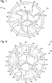
- FIG. 1 a first embodiment of a flexible guide 1 for a rotary resonator mechanism, in particular a clockwork movement, is shown.
- the flexible guide 1 is arranged substantially in one plane.
- the flexible guide comprises a fixed support 2, a mobile element 26 with respect to the fixed support 2 and two main flexible blades 3, 4.
- the main flexible blades 3, 4 allow the mobile element 20 to move with respect to the fixed support 2.
- the main blades 3, 4 are preferably of the same length and angularly distributed in a uniform manner around a central part 6 of the movable element 20 and of the flexible guide 1, so as to form a symmetrical pivot.
- the flexible guide 1 comprises two translation tables 10, 11, each translation table being joined to one end of a main flexible blade 3, 4 different.
- each translation table 10, 11 is arranged in series between the fixed support 2 and said main flexible blade 3, 4 corresponding.
- the translation table 10, 11 is joined to the fixed support 2 and to a first end of the corresponding main flexible blade 3, 4, the main flexible blade 3, 4 being joined to the central part 6 by a second end.
- the flexible guide 1 comprises two pairs, each pair being formed of a main flexible blade 3, 4 and a translation table 10, 11.
- the pairs are distributed angularly around the central part 6, each main blade 3, 4 being joined by one end to the central part 6 and the translation table 10, 11 being joined to the fixed support 2.
- the pairs, in particular the main blades 3, 4, for example form an angle of approximately 120° between them.
- the central part 6 is for example a circular cylinder portion.
- the movable element 20 comprises the central part 6.
- Each translation table 10, 11 is configured to move in translation at least in part under the effect of the movement of the main flexible blade 3, 4.
- Each translation table 10, 11 comprises at least one secondary flexible blade 7, 8 , here two secondary flexible blades 7, 8 substantially parallel, and a rigid part 13, 14.
- the secondary flexible blades 7, 8 are arranged on different lines.
- the secondary flexible blades 7, 8 are joined by one end to the same face of the rigid part 13, 14 and by another end to the fixed support 2.
- the rigid part 13, 14 forms a bend at a right angle, the elbow comprising three segments 113, 114, 115 connected together by their ends.
- the second segment 115 in the middle is substantially perpendicular to the other two 113, 114.
- the first 113 and the third segment 114 are curved at the free ends to keep a substantially concentric shape of the guide 1.
- the first 113 and third 114 segments of each table of translation 10, 11 are long enough for the end of the third segment 114 of a first table and the free end of the first segment 113 of an adjacent second table to be superimposed with respect to the center of the flexible guide 1.
- the guide 1 comprises a tertiary flexible blade 17 connecting the two translation tables 10, 11.
- the tertiary flexible blade 17 is joined to the rigid parts 13, 14 of the translation tables 10, 11. More particularly, the tertiary flexible blade 17 connects the end of the third segment 114 of a first table 11 and the end of the first segment 113 of the second table 10.
- the tertiary flexible blade 17 is directed in a radial direction passing through the center of flexible guide 1 in the rest position of guide 1.
- the tertiary flexible blade 17 avoids the movement of the translation tables 10, 11 due to gravity. Indeed, when a table 10, 11 moves towards the center of the guide 1, the other table 10, 11 also moves towards the center thanks to the tertiary flexible blade 17. Conversely, the translation tables 10, 11 move together towards the periphery of the guide 1 thanks to the flexible tertiary blade 17. Thus, the tables 10, 11 follow the same movement with respect to the center of the guide 1. This improves the precision of the running of the movement, which is less sensitive to gravity.
- the main flexible blade 3, 4 is joined to the first segment 113, while the secondary blades 7, 8 are joined to the second segment 115.
- the main flexible blades 3, 4 are substantially perpendicular to the secondary flexible blades 7, 8 of the translation table 10, 11 in the rest position of the guide 1.
- the rest position is defined when the main 3, 4 and secondary 7, 8 blades are straight, therefore not curved.
- the movable element 26 further comprises a rocker arm, not shown in the figure, which is for example in the form of a ring.
- the balance comprises an outer annular part and arms, for example three arms, joining the annular part to an axial junction with respect to the annular part.
- the arms are concentric and of the same length.
- the balance is assembled on the central part 6 by the junction.
- the central part and the junction are in one piece.
- the balance is centered with respect to the central part 6.
- the balance is formed from the same material, that is to say it is in one piece.
- the flexible blades main 3, 4 bend and have a balance spring return function to make it turn in the other direction and vice versa.
- the translation tables 10, 11 allow the main blades 3, 4 to move longitudinally at the same time as they bend.
- the rigid parts 13, 14 of the translation tables 10, 11 approach the central part 6 thanks to the secondary blades 7, 8 when the main blades 3, 4 bend, and move away from the central part 6 when the main blades 3, 4 become straight.
- an isochronism of the movement of the pendulum is preserved thanks to the translation tables 10, 11.
- the tertiary blade 17 is oriented along the bisector of the angle formed between the main blades 3, 4 in opposition to the rest of the guide 1 Equivalently, the tertiary blade 17 is preferably oriented along the bisector of the angle formed between the directions of the blades of the translation tables 10, 11.
- the flexible guide 50 is arranged substantially in one plane.
- the flexible guide comprises a fixed support 2, a mobile element 26 with respect to the fixed support 2 and three main flexible blades 3, 4, 5.
- the main flexible blades 3, 4, 5 allow the mobile element 20 to move by relative to the fixed support 2.
- the main blades 3, 4, 5 are preferably of the same length and angularly distributed in a uniform manner around a central part 6 of the movable element 20 and of the flexible guide 1, so as to form a symmetrical pivot.
- the flexible guide 1 comprises translation tables 10, 11, 12, each translation table being joined to one end of a main flexible blade 3, 4, 5 different.
- each translation table 10, 11, 12 is arranged in series between the support fixed 2 and said main flexible blade 3, 4, 5 corresponding.
- the translation table 10, 11, 12 is joined to the fixed support 2 and to a first end of the corresponding main flexible blade 3, 4, 5, the main flexible blade 3, 4, 5 being joined to the central part 6 by a second end.
- the flexible guide 1 comprises three couples, each couple being formed of a main flexible blade 3, 4, 5 and of a translation table 10, 11, 12.
- the couples are distributed angularly around the central part 6, so as to form a symmetrical pivot, each main blade 3, 4, 5 being joined by one end to the central part 6 and the translation table 10, 11, 12 being joined to the fixed support 2.
- the pairs, in particular the main blades 3, 4, 5 form an angle of approximately 120° between them.
- the central part 6 is for example a circular cylinder portion.
- the movable element 20 comprises the central part 6.
- Each translation table 10, 11, 12 is configured to move in translation at least partly under the effect of the movement of the main flexible blade 3, 4, 5.
- Each translation table 10, 11, 12 comprises at least one secondary flexible blade 7, 8, 9, here two secondary flexible blades 7, 8, 9 substantially parallel, and a rigid part 13, 14, 15.
- the secondary flexible blades 7, 8, 9 are arranged on different lines.
- the secondary flexible blades 7, 8 are joined by one end to the rigid part 13, 14, 15 and by another end to the fixed support 2.
- the rigid part 13, 14, 15 forms a bend at a right angle, the elbow comprising three segments 113, 114, 115 connected together by their ends.
- the second segment 115 in the middle is substantially perpendicular to the other two 113, 114.
- the first 113 and the third segment 114 are curved at the free ends to keep a substantially concentric shape of the guide 1.
- the first 113 and third 114 segments of each table of translation 10, 11, 12 are long enough for the end of the third segment 114 of a first table and the end free of the first segment 113 of a second adjacent table are superimposed with respect to the center of the flexible guide 1.
- the guide 1 comprises three tertiary flexible blades 16, 17, 18, each tertiary flexible blade 16, 17, 18 connecting two different translation tables 10, 11, 12.
- the tertiary flexible blades 16, 17, 18 are joined to the rigid parts 13 , 14, 15 of the translation tables 10, 11, 12. More particularly, the tertiary flexible blades 16, 17, 18 connect the end of the third segment 114 of a first table 10, 11, 12 and the end of the first segment 113 of the second table 10, 11, 12.
- the tertiary flexible blades 16, 17, 18 are directed in a radial direction passing through the center of the flexible guide 1 in the rest position of the guide 1.
- the tertiary flexible blades 16, 17, 18 avoid the movement of the translation tables 10, 11, 12 due to gravity. Indeed, when a table 10, 11, 12 moves towards the center of the guide 1, the other tables 10, 11, 12 also move towards the center thanks to the tertiary flexible blades 16, 17, 18. Conversely, the tables of translation 10, 11, 12 move together towards the periphery of the guide 1 thanks to the tertiary flexible blades 16, 17, 18. Thus, the tables 10, 11, 12 follow the same movement with respect to the center of the guide 1. thus the accuracy of the rate of the movement, which is less sensitive to gravity.
- the main flexible blade 3, 4, 5 is joined to the first segment 113, while the secondary blades 7, 8, 9 are joined to the second segment 115.
- the main flexible blades 3, 4, 5 are substantially perpendicular to the blades secondary hoses 7, 8, 9 of the translation table 10, 11, 12 in the rest position of the guide 1.
- the rest position is defined when the main 3, 4, 5 and secondary 7, 8, 9 blades are straight, so not curved.
- the balance is assembled on the central part 6 by the junction.
- the central part and the junction are in one piece.
- the pendulum is centered with respect to the central part 6.
- the balance wheel is formed from the same material, that is to say it is in one piece
- the movable element 26 comprises at least two members forming a pendulum.
- the first member 21 comprises arms 22, here three arms and an axial junction 25 in one piece.
- the arms 22 are concentric and of the same length.
- the arms 22 are provided at their free ends with an attachment platform 23 provided with holes 24 for assembling a ring, the ring defining the second member of the movable element 26 and not being represented on the picture 2 .
- the central part 6 and the axial junction 25 of the first member 21 are in one piece.
- the flexible blades main 3, 4, 5 bend and have a balance spring return function to make it turn in the other direction and vice versa.
- the translation tables 10, 11, 12 allow the main blades 3, 4, 5 to move longitudinally at the same time as they bend.
- the rigid parts 13, 14, 15 of the translation tables 10, 11, 12 approach the central part 6 thanks to the secondary blades 7, 8, 9 when the main blades 3, 4, 5 bend, and move away from the central part 6 when the main blades 3, 4, 5 become straight.
- an isochronism of the movement of the pendulum is preserved thanks to the translation tables 10, 11, 12.
- the tertiary blades 16, 17, 18 are oriented along the bisectors of the angles formed between the main blades 3, 4, 5. Equivalently, the tertiary blades 16, 17, 18 are preferably oriented along the bisectors of the angles formed between the directions of the blades of the translation tables 10, 11, 12.
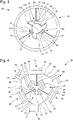
- the third embodiment of the picture 3 shows an example of a flexible guide 20 not comprising a central part like that of the second embodiment.
- the flexible guide 20 comprises a fixed support 25, a pendulum 32 of a mobile element 26, and three pairs formed by a main flexible blade 36, 37, 38 of a translation table 33, 34, 35.
- Each main blade 36, 37, 38 is joined by a first end to the rocker arm 32, and by a second end to a rigid part of a translation table 33, 34, 35.
- the torques are distributed angularly, so as to have an angle of 120 ° between the main blades 36, 37, 38.
- Each translation table 33, 34, 35 is arranged in series between a main flexible blade 36, 37, 38 and the fixed support 25.
- the translation table 33, 34, 35 is attached to the fixed support 25 and to the second end of the main flexible blade 36, 37, 38.
- the rocker arm 32 is arranged around the translation tables 33, 34, 35.
- the translation tables 33, 34, 35 are at the center of the flexible guide 20 and the rocker arm 26 at the periphery.
- the translation tables 33, 34, 35 have the same structure, the same arrangement between them, and the same shape as the translation tables of the second embodiment.
- the secondary blades 27, 28, 29 of the translation tables 33, 34, 35 are substantially perpendicular to the main blades 36, 37, 38.
- the rigid parts of the translation tables 33, 34, 35 comprise four segments, the first three 116, 117, 118 are arranged in the same way as in the second embodiment, while the fourth segment 119 is assembled to the second segment 118, which is perpendicular to the other two 116, 117.
- the fourth segment 119 is substantially parallel to the third segment 117 and the secondary blades 27, 28, 29 corresponding.
- the third segment 117 and the fourth segment 119 are arranged on either side of the secondary blades 27, 28, 29.
- the main blades 36, 37, 38 are assembled to the translation tables 10, 11, 12 by the fourth segment 119
- the tertiary blades 31, 39, 41 are preferably oriented along the bisectors of the angles formed between the main blades 36, 37, 38. Equivalently, the tertiary blades 31, 39, 41 are preferably , oriented according to bisectors of the angles formed between the directions of the translation tables 33, 34, 35.
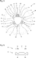
- the fourth embodiment of the flexible guide 30 of the figure 4 comprises a fixed support 52, a mobile element 26 with respect to the fixed support 52 and three main flexible blades 42, 43, 44 allowing the mobile element 20 to move with respect to the fixed support 52.
- the main blades 42, 43, 44 are preferably of the same length and angularly distributed in a uniform manner around a central part of the movable element 26, so as to form a symmetrical pivot.
- the flexible guide 30 comprises translation tables 48, 49, 51, each translation table being joined to one end of a different main flexible blade 42, 43, 44.
- the translation table 48, 49, 51 is arranged in series between the fixed support 52 and said main flexible blade 42, 43, 44 corresponding.
- the translation table 48, 49, 51 is joined to the fixed support 52 and to a first end of the corresponding main flexible blade 42, 43, 44, the main flexible blade 42, 43, 44 being joined to the movable element 26 by a second end.
- the flexible guide 30 comprises three couples, each couple being formed of a main flexible blade 42, 43, 44 and of a translation table 48, 49, 51.
- the couples are angularly distributed around the central part of the movable element 26, so as to form a symmetrical pivot, each main blade 42, 43, 44 being joined by one end to the central part 6 and the translation table 48, 49, 51 being joined to the fixed support 52.
- the main blades 42, 43, 44 form an angle of approximately 120° between them.
- Each translation table 48, 49, 51 is configured to move in translation at least in part under the effect of the movement of the main flexible blade 42, 43, 44.
- Each translation table 48, 49, 51 comprises at least least one secondary flexible blade, here two secondary flexible blades and a rigid part 45, 46, 47.
- the secondary flexible blades are joined by one end to the rigid part 45, 46, 47, and by another end to the fixed support 52.
- the rigid part 45, 46, 47 here forms a bend at a right angle, the bend comprising two substantially perpendicular segments.
- the main flexible blade 42, 43, 44 is joined to the first segment, while the secondary blades are joined to the second segment.
- the main flexible blades 42, 43, 44 are substantially perpendicular to the secondary flexible blades of the translation table 48, 49, 51, in the rest position of the guide 30.
- the rest position is defined when the main blades 42, 43, 44 and secondaries are straight, therefore not curved.
- the movable element 26 comprises at least two organs.
- the first member 21 comprises arms 22, here three arms, and an axial junction 25 in one piece.
- the arms 22 are provided at their free ends with an attachment platform 23 provided with holes 24 for assembling an inertial element, such as a weight or a ring preferably, the inertial element defining the second member and not being shown. on the figure 4 .
- the central part 6 and the first member 21 are in one piece.
- the flexible guide 30 comprises at least one secondary translation table 42, 43, 44, arranged in series between two main translation tables.
- the flexible guide 30 comprises three secondary translation tables 42, 43, 44.
- Each secondary translation table 42, 43, 44 is arranged between two translation tables 48, 49, 51.
- a secondary translation table 42, 43, 44 comprises two quaternary flexible blades and a rigid part, the quaternary flexible blades being joined to the rigid part of the secondary translation tables.
- the Quaternary flexible blades are substantially parallel and are arranged on different lines.
- the secondary flexible blades are joined to the same face of the rigid part.
- Each secondary translation table 42, 43, 44 is connected to two main translation tables 48, 49, 51 by a tertiary flexible blade 53, 54, 55, 56, 57, 58.
- a tertiary flexible blade 53, 54, 55, 56, 57, 58 connects a main translation table 48, 49, 51 to a secondary translation table 42, 43, 44.
- a secondary translation table 42, 43, 44 comprises two tertiary flexible blades and a rigid part.
- the rigid part here has a parallelepipedal shape, which is oriented in a direction directed towards the center of the flexible guide 30.
- the quaternary flexible blades connect the rigid part of the secondary translation table to the support 52.
- the flexible guide 30 therefore comprises blades tertiary flexibles 53, 54, 55, 56, 57, 58 connecting the secondary translation tables 42, 43, 44 to the main translation tables 48, 49, 51.
- Each tertiary flexible blade 53, 54, 55, 56, 57, 58 connects a secondary translation table 42, 43, 44 to an adjacent main translation table 48, 49, 51.
- the tertiary flexible blades 53, 54, 55, 56, 57, 58 are joined to the rigid part 45, 46, 47 of the main translation tables 48, 49, 51, preferably to the segment of the rigid part 45, 46, 47 perpendicular to the main flexible blades 42, 43, 44.
- the tertiary flexible blades 53, 54, 55, 56, 57, 58 are substantially of the same length.
- Each secondary translation table 42, 43, 44 is arranged at an equal distance from the two main translation tables 48, 49, 51 to which it is joined.
- the secondary translation tables 42, 43, 44 can move in a direction directed towards the center of the flexible guide 30. of gravity.
- the embodiment of the flexible guide 40 of the figure 5 also includes main 64, 65, 66 and secondary 67 translation tables, 68, 69, but it comprises a mobile element 26 arranged at the periphery of the flexible guide 40, and does not comprise a central part like the embodiment of the picture 3 .
- the arrangement of the main 64, 65, 66 and secondary 67, 68, 69 translation tables is the same as that of the embodiment of the figure 4 .
- the flexible guide 40 comprises a fixed support 72, a movable element 26 relative to the fixed support 72 and three main flexible blades 61, 62, 63 allowing the movable element 26 to move relative to the fixed support 72.
- the main blades 61, 62, 63 are preferably of the same length and angularly distributed in a uniform manner around a central part of the movable element 26, so as to form a symmetrical pivot.
- the flexible guide 40 comprises main translation tables 64, 65, 66, each translation table being joined to one end of a different main flexible blade 61, 62, 63.
- the main translation table 64, 65, 66 is arranged in series between the fixed support 72 and said main flexible blade 61, 62, 63 corresponding.
- the main translation table 64, 65, 66 is joined to the fixed support 72 and to a first end of the corresponding main flexible blade 61, 62, 63, the main flexible blade 61, 62, 63 being joined to the movable element 26 by a second end.
- the flexible guide 40 comprises three couples, each couple being formed of a main flexible blade 61, 62, 63 and of a main translation table 64, 65, 66.
- the couples are distributed angularly, so as to form a symmetrical pivot, each main blade 61, 62, 63 being joined by one end to the movable element 26, and the translation table 64, 65, 66 being joined to the fixed support 72.
- the pairs, in particular the main blades 61, 62 , 63 form an angle of approximately 120° between them.
- Each main translation table 64, 65, 66 is configured to move in translation at least partly under the effect of the movement of the main flexible blade 61, 62, 63.
- Each main translation table 64, 65, 66 comprises at least one secondary flexible blade, here two secondary flexible blades and a rigid part.
- the secondary flexible blades are substantially parallel and are arranged on different lines.
- the secondary flexible blades are joined by one end to the same face of the rigid part, and by another end to the fixed support 72.
- the rigid part here forms a U-shaped bend, the bend comprising three segments 121, 122, 123.
- the main flexible blade 61, 62, 63 is joined to the first segment 123, while the secondary blades are joined to the second segment 122.
- the main flexible blades 61, 62, 63 are substantially perpendicular to the secondary flexible blades of the translation table 64, 65, 66, in the rest position of the guide 40.
- the rest position is defined when the main 61, 62, 63 and secondary blades are straight, therefore not curved.
- the flexible guide 40 comprises at least one secondary translation table 67, 68, 69, arranged in series between two main translation tables 64, 65, 66.
- the flexible guide 30 comprises three secondary translation tables 67, 68, 69. Each secondary translation table 67, 68, 69 is arranged between two translation tables 64, 65, 66.
- Each secondary translation table 67, 68, 69 is connected to two main translation tables 64, 65, 69 by a tertiary flexible blade 73, 74, 75, 76, 77, 78.
- a tertiary flexible blade 73, 74, 75, 76, 77, 78 connects a main translation table 64, 65, 69 to a secondary translation table 67, 68, 69.
- a secondary translation table 67, 68, 69 comprises two quaternary flexible blades and a rigid part, the quaternary flexible blades being joined to the rigid part of the secondary translation tables 67, 68, 69 and to the support 72.
- the rigid part here has a shape parallelepiped, which is oriented in a direction directed towards the center of the flexible guide 40.
- the flexible guide 40 comprises tertiary flexible blades 73, 74, 75, 76, 77, 78 connecting the secondary translation tables 67, 68, 69 to the tables translation main 64, 65, 69.
- Each tertiary flexible blades 73, 74, 75, 76, 77, 78 connects a secondary translation table 67, 68, 69 to a main translation table 64, 65, 69 adjacent.
- the tertiary flexible blades 73, 74, 75, 76, 77, 78 are joined to the rigid part of the translation tables, preferably to the third segment 121 of the rigid part perpendicular to the main flexible blades 61, 62, 63.
- the flexible blades tertiary 73, 74, 75, 76, 77, 78 are substantially the same length.
- Each secondary translation table 67, 68, 69 is arranged at an equal distance from the two main translation tables 64, 65, 69 to which it is attached.
- the flexible blades are flat blades.
- the flexible blades can also include more or less thick parts, or include necks, like those represented on the figure 6 .
- the upper blade 80 comprises a thicker part 82 in the middle, which is more rigid, and thinner parts 83 at the ends.
- the bottom slat 81 is thick throughout the length 84, but includes two necks 85 tapered at the ends to allow the slat 81 to flex.
- the fixed support comprises the central part 89, 93 on which the first ends of the main flexible blades are joined, while the translation tables are joined to the movable element.
- the sixth embodiment of the flexible guide 50 is similar to the flexible guide 1 of the figure 2 , with the difference that the secondary blades of the main translation tables 90, 91, 92, are joined to the movable element 26, while the main blades 83, 84, 85 are joined on the one hand to the central part of the fixed support 82, and on the other hand to the rigid part of the main translation tables 90, 91 , 92.
- the tertiary flexible blades 125, 126, 127 are arranged in series between the main translation tables 90, 91, 92 in the same configuration as the second embodiment.
- the central part 89 also has the shape of a circular cylindrical portion.
- the movable element 32 comprises internal extensions 84 oriented in the plane towards the inside of the ring, in order to allow the assembly of the secondary flexible blades of each translation table 90, 91, 92.
- the extensions 84 extend in a direction substantially parallel to the direction of the main flexible blades 86, 87, 88 in the rest position, so that the secondary flexible blades of each translation table 90, 91, 92 are directed perpendicular to this direction.
- the secondary flexible strips are substantially perpendicular to the direction of the main flexible strips 86, 87, 88 for the same pair.
- the translation tables 90, 91, 92 are not joined directly to the fixed support 89, but to the movable element 26.
- the flexible guide 60 is similar to the flexible guide 30 of the figure 4 , with the difference that the secondary blades of the main translation tables 94, 95, 96, are joined to the movable element 26, while the main blades 97, 98, 99 are joined on the one hand to the central part of the support fixed 93, and on the other hand to the rigid part of the main translation tables 94, 95, 96.
- the tertiary flexible blades 105, 106, 107, 108, 109, 110, 111 are arranged in series between the main translation tables 90, 91, 92 and the secondary translation tables 100, 101, 102 in the same configuration as the fourth embodiment.
- the central part of the support 93 has the shape of a circular cylindrical portion.
- the movable element 32 comprises internal extensions 103, 104 oriented in the plane towards the inside of the ring, in order to allow the assembly of the secondary flexible blades and quaternary translation tables main 94, 95, 96 and secondary 100, 101, 102.
- the extensions 103, 104 extend in a direction substantially parallel to the direction of the main flexible blades 97, 98, 99 in the rest position, so that the secondary flexible blades of the main translation tables 94, 95, 96 are directed perpendicular to this direction.
- the secondary flexible blades are substantially perpendicular to the direction of the main flexible blades 97, 98, 99.
- the translation tables 97, 98, 99, 100, 101, 102 are not joined directly to the support fixed 93, but to the movable element 32.
- the invention also relates to a resonator mechanism, in particular for a clock movement, not shown in the figures.
- the resonator mechanism is provided with a flexible guide according to one of the embodiments described above.
Landscapes
- Physics & Mathematics (AREA)
- General Physics & Mathematics (AREA)
- Engineering & Computer Science (AREA)
- General Engineering & Computer Science (AREA)
- Mechanical Engineering (AREA)
- Machine Tool Units (AREA)
- Other Liquid Machine Or Engine Such As Wave Power Use (AREA)
- Transmission Devices (AREA)
- Motorcycle And Bicycle Frame (AREA)
Priority Applications (4)
| Application Number | Priority Date | Filing Date | Title |
|---|---|---|---|
| EP20204749.4A EP3992729A1 (de) | 2020-10-29 | 2020-10-29 | Flexible führung mit verschiebetisch für einen rotierenden resonatormechanismus, insbesondere eines uhrwerks |
| US17/486,010 US12085894B2 (en) | 2020-10-29 | 2021-09-27 | Flexible guide with translation table for a rotating resonator mechanism, in particular for a horological movement |
| JP2021163283A JP7227329B2 (ja) | 2020-10-29 | 2021-10-04 | 回転式共振機構、特に、計時器用ムーブメントの回転式共振機構、のための並進運動構造を備えるフレキシブルガイド |
| CN202111272945.5A CN114428447B (zh) | 2020-10-29 | 2021-10-29 | 用于旋转谐振器机构的具有平移台的柔性引导件,尤其用于钟表机芯 |
Applications Claiming Priority (1)
| Application Number | Priority Date | Filing Date | Title |
|---|---|---|---|
| EP20204749.4A EP3992729A1 (de) | 2020-10-29 | 2020-10-29 | Flexible führung mit verschiebetisch für einen rotierenden resonatormechanismus, insbesondere eines uhrwerks |
Publications (1)
| Publication Number | Publication Date |
|---|---|
| EP3992729A1 true EP3992729A1 (de) | 2022-05-04 |
Family
ID=73039922
Family Applications (1)
| Application Number | Title | Priority Date | Filing Date |
|---|---|---|---|
| EP20204749.4A Pending EP3992729A1 (de) | 2020-10-29 | 2020-10-29 | Flexible führung mit verschiebetisch für einen rotierenden resonatormechanismus, insbesondere eines uhrwerks |
Country Status (4)
| Country | Link |
|---|---|
| US (1) | US12085894B2 (de) |
| EP (1) | EP3992729A1 (de) |
| JP (1) | JP7227329B2 (de) |
| CN (1) | CN114428447B (de) |
Cited By (1)
| Publication number | Priority date | Publication date | Assignee | Title |
|---|---|---|---|---|
| WO2024100597A1 (en) | 2022-11-09 | 2024-05-16 | Ecole Polytechnique Federale De Lausanne (Epfl) | Pivot, process for manufacturing such a pivot, oscillator comprising such a pivot, watch movement and timepiece comprising such an oscillator |
Families Citing this family (1)
| Publication number | Priority date | Publication date | Assignee | Title |
|---|---|---|---|---|
| EP4707946A1 (de) | 2024-09-09 | 2026-03-11 | Ecole Polytechnique Federale De Lausanne (Epfl) | Biegemechanismus mit reduzierter steifigkeit |
Citations (1)
| Publication number | Priority date | Publication date | Assignee | Title |
|---|---|---|---|---|
| EP3722888A1 (de) * | 2019-04-09 | 2020-10-14 | Ecole Polytechnique Fédérale de Lausanne (EPFL) | Mechanischer oszillator mit abstimmbarem isochronismusmangel |
Family Cites Families (13)
| Publication number | Priority date | Publication date | Assignee | Title |
|---|---|---|---|---|
| KR101036127B1 (ko) * | 2008-06-27 | 2011-05-23 | 주식회사 에이스테크놀로지 | Rf 필터의 공진기 제조 방법 및 그 공진기를 구비한 rf필터 |
| US9201398B2 (en) * | 2010-07-19 | 2015-12-01 | Nivarox-Far S.A. | Oscillating mechanism with an elastic pivot and mobile element for transmitting energy |
| CN106662839B (zh) * | 2015-02-03 | 2019-03-29 | Eta瑞士钟表制造股份有限公司 | 等时钟表谐振器 |
| CH713069A2 (fr) * | 2016-10-25 | 2018-04-30 | Eta Sa Mft Horlogere Suisse | Montre mécanique avec résonateur rotatif isochrone, insensible aux positions. |
| CH714019A2 (fr) | 2017-07-26 | 2019-01-31 | Eta Sa Mft Horlogere Suisse | Mouvement mécanique d'horlogerie avec résonateur rotatif. |
| EP3438762B1 (de) | 2017-07-28 | 2026-04-29 | The Swatch Group Research and Development Ltd | Uhrwerkoszillator mit flexiblen führungen mit grosser winkelförmiger laufbahn |
| EP3435172B1 (de) | 2017-07-28 | 2021-11-24 | The Swatch Group Research and Development Ltd | Herstellungsverfahren eines flexiblen führungsmechanismus für mechanischen oszillator eines uhrwerks |
| EP3561607B1 (de) | 2018-04-23 | 2022-03-16 | ETA SA Manufacture Horlogère Suisse | Stossdämpfungsschutz eines resonatormechanismus mit flexibler drehführung |
| EP3824353B1 (de) * | 2018-07-16 | 2023-11-29 | Patek Philippe SA Genève | Schwerkraftunempfindlicher biegeschwenkoszillator |
| JP6843191B2 (ja) * | 2018-07-24 | 2021-03-17 | ザ・スウォッチ・グループ・リサーチ・アンド・ディベロップメント・リミテッド | 長い角ストロークを有するフレクシャーベアリングを備えた計時器用発振器 |
| US11454932B2 (en) * | 2018-07-24 | 2022-09-27 | The Swatch Group Research And Development Ltd | Method for making a flexure bearing mechanism for a mechanical timepiece oscillator |
| CH715526A2 (fr) * | 2018-11-08 | 2020-05-15 | Eta Sa Mft Horlogere Suisse | Protection antichoc d'un mécanisme résonateur à guidage flexible rotatif. |
| US11409245B2 (en) * | 2018-11-08 | 2022-08-09 | Eta Sa Manufacture Horlogere Suisse | Anti shock protection for a resonator mechanism with a rotary flexure bearing |
-
2020
- 2020-10-29 EP EP20204749.4A patent/EP3992729A1/de active Pending
-
2021
- 2021-09-27 US US17/486,010 patent/US12085894B2/en active Active
- 2021-10-04 JP JP2021163283A patent/JP7227329B2/ja active Active
- 2021-10-29 CN CN202111272945.5A patent/CN114428447B/zh active Active
Patent Citations (1)
| Publication number | Priority date | Publication date | Assignee | Title |
|---|---|---|---|---|
| EP3722888A1 (de) * | 2019-04-09 | 2020-10-14 | Ecole Polytechnique Fédérale de Lausanne (EPFL) | Mechanischer oszillator mit abstimmbarem isochronismusmangel |
Non-Patent Citations (1)
| Title |
|---|
| "Flexure Pivot Oscillators for Mechanical Watches", 18 June 2020, article ETIENNE F. G. THALMANN: "Flexure Pivot Oscillators for Mechanical Watches", XP055731304, DOI: 10.5075/epfl-thesis-8802 * |
Cited By (1)
| Publication number | Priority date | Publication date | Assignee | Title |
|---|---|---|---|---|
| WO2024100597A1 (en) | 2022-11-09 | 2024-05-16 | Ecole Polytechnique Federale De Lausanne (Epfl) | Pivot, process for manufacturing such a pivot, oscillator comprising such a pivot, watch movement and timepiece comprising such an oscillator |
Also Published As
| Publication number | Publication date |
|---|---|
| JP2022073997A (ja) | 2022-05-17 |
| US20220137560A1 (en) | 2022-05-05 |
| US12085894B2 (en) | 2024-09-10 |
| JP7227329B2 (ja) | 2023-02-21 |
| CN114428447A (zh) | 2022-05-03 |
| CN114428447B (zh) | 2025-06-10 |
Similar Documents
| Publication | Publication Date | Title |
|---|---|---|
| EP3457221B1 (de) | Oszillator einer uhr mit flexiblem zapfen | |
| EP3355130B1 (de) | Resonatormechanismus eines uhrwerks | |
| EP3992730B1 (de) | Flexible führung mit regulierbarem verschiebetisch für einen rotierenden resonatormechanismus, insbesondere eines uhrwerks | |
| EP4016194B1 (de) | Resonatormechanismus eines uhrwerks mit flexibler führung, die mit mitteln zur einstellung der steifigkeit ausgestattet ist | |
| EP4009115A1 (de) | Spiralfeder für resonatormechanismus eines uhrwerks, der mit mitteln zum ausgleichen der starrheit ausgestattet ist | |
| EP3293584B1 (de) | Oszillatormechanismus für uhr | |
| EP3200029B1 (de) | Resonatormechanismus eines uhrwerks | |
| EP2911012A1 (de) | Oszillator einer Uhr | |
| EP4012506B1 (de) | Resonatormechanismus eines uhrwerks, der mit einem verschieberahmen ausgestattet ist | |
| EP3316047B1 (de) | Mechanische armbanduhr mit einem isochronen sich drehenden resonator, der positionsunempfindlich ist | |
| CH717996A2 (fr) | Guidage flexible avec table de translation pour mécanisme résonateur rotatif, notamment d'un mouvement d'horlogerie. | |
| EP3792700B1 (de) | Oszillator einer uhr mit flexiblem zapfen | |
| EP3992729A1 (de) | Flexible führung mit verschiebetisch für einen rotierenden resonatormechanismus, insbesondere eines uhrwerks | |
| CH718113A2 (fr) | Ressort-spiral pour mécanisme résonateur d'horlogerie muni de moyens d'ajustement de la rigidité. | |
| EP3561606B1 (de) | Stossdämpfungsschutz eines resonators mit rcc-schwenkfedern | |
| EP3839651B1 (de) | Mechanischer oszillator einer uhr mit flexibler führung | |
| EP3054356A1 (de) | Isochroner Resonator für Uhr | |
| CH718169A2 (fr) | Mécanisme résonateur d'horlogerie à guidage flexible muni de moyens d'ajustement de la rigidité. | |
| EP3812843A1 (de) | Flexible führung und gesamtheit von übereinander angeordneten flexiblen führungen für sich drehenden resonatormechanismus, insbesondere für uhrwerk | |
| EP4009113A1 (de) | Gesamtheit von flexiblen führungen für sich drehenden resonatormechanismus, insbesondere für uhrwerk | |
| EP3812842B1 (de) | Schwenkbare führungsvorrichtung für eine schwenkbare masse, und resonatormechanismus einer uhr | |
| CH717997A2 (fr) | Guidage flexible avec table de translation pour mécanisme résonateur rotatif, notamment d'un mouvement d'horlogerie. | |
| CH716725A2 (fr) | Dispositif de guidage en pivotement pour une masse pivotante et mécanisme résonateur d'horlogerie. | |
| EP4202567A1 (de) | Anordnung von entgegengesetzten flexiblen führungen für ein uhrwerk, insbesondere für eine anzeigevorrichtung | |
| EP3992728A1 (de) | Flexible führung mit verschiebetisch für einen rotierenden resonatormechanismus, insbesondere eines uhrwerks |
Legal Events
| Date | Code | Title | Description |
|---|---|---|---|
| PUAI | Public reference made under article 153(3) epc to a published international application that has entered the european phase |
Free format text: ORIGINAL CODE: 0009012 |
|
| STAA | Information on the status of an ep patent application or granted ep patent |
Free format text: STATUS: THE APPLICATION HAS BEEN PUBLISHED |
|
| AK | Designated contracting states |
Kind code of ref document: A1 Designated state(s): AL AT BE BG CH CY CZ DE DK EE ES FI FR GB GR HR HU IE IS IT LI LT LU LV MC MK MT NL NO PL PT RO RS SE SI SK SM TR |
|
| STAA | Information on the status of an ep patent application or granted ep patent |
Free format text: STATUS: REQUEST FOR EXAMINATION WAS MADE |
|
| 17P | Request for examination filed |
Effective date: 20221104 |
|
| RBV | Designated contracting states (corrected) |
Designated state(s): AL AT BE BG CH CY CZ DE DK EE ES FI FR GB GR HR HU IE IS IT LI LT LU LV MC MK MT NL NO PL PT RO RS SE SI SK SM TR |
|
| P01 | Opt-out of the competence of the unified patent court (upc) registered |
Effective date: 20230615 |
|
| STAA | Information on the status of an ep patent application or granted ep patent |
Free format text: STATUS: EXAMINATION IS IN PROGRESS |
|
| 17Q | First examination report despatched |
Effective date: 20240704 |
|
| REG | Reference to a national code |
Ref country code: DE Ref legal event code: R079 Free format text: PREVIOUS MAIN CLASS: G04B0017040000 Ipc: F16C0027060000 Ref country code: DE Ref legal event code: R079 Ref document number: 602020072232 Country of ref document: DE Free format text: PREVIOUS MAIN CLASS: G04B0017040000 Ipc: F16C0027060000 |
|
| GRAP | Despatch of communication of intention to grant a patent |
Free format text: ORIGINAL CODE: EPIDOSNIGR1 |
|
| STAA | Information on the status of an ep patent application or granted ep patent |
Free format text: STATUS: GRANT OF PATENT IS INTENDED |
|
| RIC1 | Information provided on ipc code assigned before grant |
Ipc: G04B 17/04 20060101ALI20251211BHEP Ipc: F16C 27/06 20060101AFI20251211BHEP Ipc: F16C 11/12 20060101ALI20251211BHEP |
|
| INTG | Intention to grant announced |
Effective date: 20260102 |
|
| GRAS | Grant fee paid |
Free format text: ORIGINAL CODE: EPIDOSNIGR3 |
|
| GRAA | (expected) grant |
Free format text: ORIGINAL CODE: 0009210 |
|
| STAA | Information on the status of an ep patent application or granted ep patent |
Free format text: STATUS: THE PATENT HAS BEEN GRANTED |