EP3994042B1 - Verfahren zur bestimmung eines ausweichweges eines kraftfahrzeuges - Google Patents
Verfahren zur bestimmung eines ausweichweges eines kraftfahrzeuges Download PDFInfo
- Publication number
- EP3994042B1 EP3994042B1 EP20730269.6A EP20730269A EP3994042B1 EP 3994042 B1 EP3994042 B1 EP 3994042B1 EP 20730269 A EP20730269 A EP 20730269A EP 3994042 B1 EP3994042 B1 EP 3994042B1
- Authority
- EP
- European Patent Office
- Prior art keywords
- obstacle
- motor vehicle
- avoidance path
- determining
- avoidance
- Prior art date
- Legal status (The legal status is an assumption and is not a legal conclusion. Google has not performed a legal analysis and makes no representation as to the accuracy of the status listed.)
- Active
Links
Images

Classifications
-
- B—PERFORMING OPERATIONS; TRANSPORTING
- B60—VEHICLES IN GENERAL
- B60W—CONJOINT CONTROL OF VEHICLE SUB-UNITS OF DIFFERENT TYPE OR DIFFERENT FUNCTION; CONTROL SYSTEMS SPECIALLY ADAPTED FOR HYBRID VEHICLES; ROAD VEHICLE DRIVE CONTROL SYSTEMS FOR PURPOSES NOT RELATED TO THE CONTROL OF A PARTICULAR SUB-UNIT
- B60W60/00—Drive control systems specially adapted for autonomous road vehicles
- B60W60/001—Planning or execution of driving tasks
- B60W60/0011—Planning or execution of driving tasks involving control alternatives for a single driving scenario, e.g. planning several paths to avoid obstacles
-
- B—PERFORMING OPERATIONS; TRANSPORTING
- B60—VEHICLES IN GENERAL
- B60W—CONJOINT CONTROL OF VEHICLE SUB-UNITS OF DIFFERENT TYPE OR DIFFERENT FUNCTION; CONTROL SYSTEMS SPECIALLY ADAPTED FOR HYBRID VEHICLES; ROAD VEHICLE DRIVE CONTROL SYSTEMS FOR PURPOSES NOT RELATED TO THE CONTROL OF A PARTICULAR SUB-UNIT
- B60W30/00—Purposes of road vehicle drive control systems not related to the control of a particular sub-unit, e.g. of systems using conjoint control of vehicle sub-units
- B60W30/08—Active safety systems predicting or avoiding probable or impending collision or attempting to minimise its consequences
- B60W30/09—Taking automatic action to avoid collision, e.g. braking and steering
-
- B—PERFORMING OPERATIONS; TRANSPORTING
- B60—VEHICLES IN GENERAL
- B60W—CONJOINT CONTROL OF VEHICLE SUB-UNITS OF DIFFERENT TYPE OR DIFFERENT FUNCTION; CONTROL SYSTEMS SPECIALLY ADAPTED FOR HYBRID VEHICLES; ROAD VEHICLE DRIVE CONTROL SYSTEMS FOR PURPOSES NOT RELATED TO THE CONTROL OF A PARTICULAR SUB-UNIT
- B60W30/00—Purposes of road vehicle drive control systems not related to the control of a particular sub-unit, e.g. of systems using conjoint control of vehicle sub-units
- B60W30/08—Active safety systems predicting or avoiding probable or impending collision or attempting to minimise its consequences
- B60W30/095—Predicting travel path or likelihood of collision
-
- B—PERFORMING OPERATIONS; TRANSPORTING
- B60—VEHICLES IN GENERAL
- B60W—CONJOINT CONTROL OF VEHICLE SUB-UNITS OF DIFFERENT TYPE OR DIFFERENT FUNCTION; CONTROL SYSTEMS SPECIALLY ADAPTED FOR HYBRID VEHICLES; ROAD VEHICLE DRIVE CONTROL SYSTEMS FOR PURPOSES NOT RELATED TO THE CONTROL OF A PARTICULAR SUB-UNIT
- B60W30/00—Purposes of road vehicle drive control systems not related to the control of a particular sub-unit, e.g. of systems using conjoint control of vehicle sub-units
- B60W30/08—Active safety systems predicting or avoiding probable or impending collision or attempting to minimise its consequences
- B60W30/095—Predicting travel path or likelihood of collision
- B60W30/0953—Predicting travel path or likelihood of collision the prediction being responsive to vehicle dynamic parameters
-
- B—PERFORMING OPERATIONS; TRANSPORTING
- B60—VEHICLES IN GENERAL
- B60W—CONJOINT CONTROL OF VEHICLE SUB-UNITS OF DIFFERENT TYPE OR DIFFERENT FUNCTION; CONTROL SYSTEMS SPECIALLY ADAPTED FOR HYBRID VEHICLES; ROAD VEHICLE DRIVE CONTROL SYSTEMS FOR PURPOSES NOT RELATED TO THE CONTROL OF A PARTICULAR SUB-UNIT
- B60W30/00—Purposes of road vehicle drive control systems not related to the control of a particular sub-unit, e.g. of systems using conjoint control of vehicle sub-units
- B60W30/08—Active safety systems predicting or avoiding probable or impending collision or attempting to minimise its consequences
- B60W30/095—Predicting travel path or likelihood of collision
- B60W30/0956—Predicting travel path or likelihood of collision the prediction being responsive to traffic or environmental parameters
-
- B—PERFORMING OPERATIONS; TRANSPORTING
- B60—VEHICLES IN GENERAL
- B60W—CONJOINT CONTROL OF VEHICLE SUB-UNITS OF DIFFERENT TYPE OR DIFFERENT FUNCTION; CONTROL SYSTEMS SPECIALLY ADAPTED FOR HYBRID VEHICLES; ROAD VEHICLE DRIVE CONTROL SYSTEMS FOR PURPOSES NOT RELATED TO THE CONTROL OF A PARTICULAR SUB-UNIT
- B60W40/00—Estimation or calculation of non-directly measurable driving parameters for road vehicle drive control systems not related to the control of a particular sub unit, e.g. by using mathematical models
- B60W40/02—Estimation or calculation of non-directly measurable driving parameters for road vehicle drive control systems not related to the control of a particular sub unit, e.g. by using mathematical models related to ambient conditions
- B60W40/04—Traffic conditions
-
- B—PERFORMING OPERATIONS; TRANSPORTING
- B60—VEHICLES IN GENERAL
- B60W—CONJOINT CONTROL OF VEHICLE SUB-UNITS OF DIFFERENT TYPE OR DIFFERENT FUNCTION; CONTROL SYSTEMS SPECIALLY ADAPTED FOR HYBRID VEHICLES; ROAD VEHICLE DRIVE CONTROL SYSTEMS FOR PURPOSES NOT RELATED TO THE CONTROL OF A PARTICULAR SUB-UNIT
- B60W50/00—Details of control systems for road vehicle drive control not related to the control of a particular sub-unit, e.g. process diagnostic or vehicle driver interfaces
- B60W50/0097—Predicting future conditions
-
- B—PERFORMING OPERATIONS; TRANSPORTING
- B60—VEHICLES IN GENERAL
- B60W—CONJOINT CONTROL OF VEHICLE SUB-UNITS OF DIFFERENT TYPE OR DIFFERENT FUNCTION; CONTROL SYSTEMS SPECIALLY ADAPTED FOR HYBRID VEHICLES; ROAD VEHICLE DRIVE CONTROL SYSTEMS FOR PURPOSES NOT RELATED TO THE CONTROL OF A PARTICULAR SUB-UNIT
- B60W60/00—Drive control systems specially adapted for autonomous road vehicles
- B60W60/001—Planning or execution of driving tasks
- B60W60/0015—Planning or execution of driving tasks specially adapted for safety
-
- B—PERFORMING OPERATIONS; TRANSPORTING
- B60—VEHICLES IN GENERAL
- B60W—CONJOINT CONTROL OF VEHICLE SUB-UNITS OF DIFFERENT TYPE OR DIFFERENT FUNCTION; CONTROL SYSTEMS SPECIALLY ADAPTED FOR HYBRID VEHICLES; ROAD VEHICLE DRIVE CONTROL SYSTEMS FOR PURPOSES NOT RELATED TO THE CONTROL OF A PARTICULAR SUB-UNIT
- B60W60/00—Drive control systems specially adapted for autonomous road vehicles
- B60W60/001—Planning or execution of driving tasks
- B60W60/0027—Planning or execution of driving tasks using trajectory prediction for other traffic participants
- B60W60/00274—Planning or execution of driving tasks using trajectory prediction for other traffic participants considering possible movement changes
-
- B—PERFORMING OPERATIONS; TRANSPORTING
- B60—VEHICLES IN GENERAL
- B60W—CONJOINT CONTROL OF VEHICLE SUB-UNITS OF DIFFERENT TYPE OR DIFFERENT FUNCTION; CONTROL SYSTEMS SPECIALLY ADAPTED FOR HYBRID VEHICLES; ROAD VEHICLE DRIVE CONTROL SYSTEMS FOR PURPOSES NOT RELATED TO THE CONTROL OF A PARTICULAR SUB-UNIT
- B60W2554/00—Input parameters relating to objects
- B60W2554/20—Static objects
-
- B—PERFORMING OPERATIONS; TRANSPORTING
- B60—VEHICLES IN GENERAL
- B60W—CONJOINT CONTROL OF VEHICLE SUB-UNITS OF DIFFERENT TYPE OR DIFFERENT FUNCTION; CONTROL SYSTEMS SPECIALLY ADAPTED FOR HYBRID VEHICLES; ROAD VEHICLE DRIVE CONTROL SYSTEMS FOR PURPOSES NOT RELATED TO THE CONTROL OF A PARTICULAR SUB-UNIT
- B60W2554/00—Input parameters relating to objects
- B60W2554/40—Dynamic objects, e.g. animals, windblown objects
-
- B—PERFORMING OPERATIONS; TRANSPORTING
- B60—VEHICLES IN GENERAL
- B60W—CONJOINT CONTROL OF VEHICLE SUB-UNITS OF DIFFERENT TYPE OR DIFFERENT FUNCTION; CONTROL SYSTEMS SPECIALLY ADAPTED FOR HYBRID VEHICLES; ROAD VEHICLE DRIVE CONTROL SYSTEMS FOR PURPOSES NOT RELATED TO THE CONTROL OF A PARTICULAR SUB-UNIT
- B60W2554/00—Input parameters relating to objects
- B60W2554/40—Dynamic objects, e.g. animals, windblown objects
- B60W2554/404—Characteristics
- B60W2554/4041—Position
-
- B—PERFORMING OPERATIONS; TRANSPORTING
- B60—VEHICLES IN GENERAL
- B60W—CONJOINT CONTROL OF VEHICLE SUB-UNITS OF DIFFERENT TYPE OR DIFFERENT FUNCTION; CONTROL SYSTEMS SPECIALLY ADAPTED FOR HYBRID VEHICLES; ROAD VEHICLE DRIVE CONTROL SYSTEMS FOR PURPOSES NOT RELATED TO THE CONTROL OF A PARTICULAR SUB-UNIT
- B60W2554/00—Input parameters relating to objects
- B60W2554/80—Spatial relation or speed relative to objects
-
- B—PERFORMING OPERATIONS; TRANSPORTING
- B60—VEHICLES IN GENERAL
- B60W—CONJOINT CONTROL OF VEHICLE SUB-UNITS OF DIFFERENT TYPE OR DIFFERENT FUNCTION; CONTROL SYSTEMS SPECIALLY ADAPTED FOR HYBRID VEHICLES; ROAD VEHICLE DRIVE CONTROL SYSTEMS FOR PURPOSES NOT RELATED TO THE CONTROL OF A PARTICULAR SUB-UNIT
- B60W2554/00—Input parameters relating to objects
- B60W2554/80—Spatial relation or speed relative to objects
- B60W2554/801—Lateral distance
-
- B—PERFORMING OPERATIONS; TRANSPORTING
- B60—VEHICLES IN GENERAL
- B60W—CONJOINT CONTROL OF VEHICLE SUB-UNITS OF DIFFERENT TYPE OR DIFFERENT FUNCTION; CONTROL SYSTEMS SPECIALLY ADAPTED FOR HYBRID VEHICLES; ROAD VEHICLE DRIVE CONTROL SYSTEMS FOR PURPOSES NOT RELATED TO THE CONTROL OF A PARTICULAR SUB-UNIT
- B60W2554/00—Input parameters relating to objects
- B60W2554/80—Spatial relation or speed relative to objects
- B60W2554/802—Longitudinal distance
Definitions
- the present invention relates generally to motor vehicle driving aids and autonomous vehicles.
- It relates more particularly to a method for determining an avoidance trajectory of a motor vehicle after an obstacle has been detected on the trajectory of this vehicle.
- It also relates to a device for implementing such a method.
- the document US 2018/099667 A1 shows a driver assistance system that generates trajectories to avoid collisions.
- the document DE102013009252 describes a system for calculating an avoidance trajectory and controlling a vehicle control unit so as to follow this avoidance trajectory.
- the avoidance trajectory is calculated based on an initial position, a desired final position of the vehicle and a polynomial trajectory model.
- the present invention proposes a new solution for calculating the avoidance trajectory.
- the invention proposes a method for determining an avoidance trajectory of a vehicle according to claim 1.
- the invention is intended to detect the dynamic position of a theoretical point called impact, which is the limit position through which one prohibits oneself from passing in order to avoid hitting the obstacle, or several obstacles, this while respecting a minimum safety distance between the vehicle and each of the obstacles.
- the invention makes it possible to avoid calculating a temporary avoidance trajectory.
- said at least one minimum safety distance is oriented relative to the motor vehicle, so as to have at least one longitudinal component relative to the longitudinal axis of the motor vehicle, and preferably also a lateral component.
- said minimum safety distance is calculated according to the movement of the target using the longitudinal and lateral speeds, which makes it possible to make this safety distance more robust with a view to obstacle avoidance despite possible errors in the safety radius sensors.
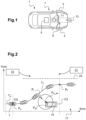
- a motor vehicle 1 is shown on the figure 1 .
- the vehicle here depicted is a car, but it could of course be another type of vehicle, typically a truck.
- This motor vehicle 1 includes two 3-wheel steering front wheels.
- It also has a conventional steering system which allows the orientation of the front wheels 3 to be influenced so as to be able to turn the vehicle.
- the steering system comprises a control member, and more precisely an actuator making it possible to act on the orientation (i.e. the steering) of the front wheels as a function of the orientation of the steering wheel and/or as a function of a request received from a computer 5.
- This computer 5 is for example a computer dedicated to driving aids.
- the motor vehicle may include a differential braking system controlled by the same 5 or another computer and making it possible to act differently on the rotation speeds of the front wheels so as to slow down the motor vehicle by making it turn.
- the computer 5 is programmed to control the power steering actuator and possibly also the differential brake actuator.
- it comprises at least one processor, at least one memory and various input and output interfaces.
- the calculator 5 is adapted to receive input signals coming from a detection system 9.
- This detection system 9 here includes different sensors.
- a front camera 11 is provided here, making it possible to locate the position of the motor vehicle 1 in relation to its traffic lane.
- a telemetry unit 13 comprising at least one telemetry sensor (RADAR, LIDAR, SONAR) placed at the front of the motor vehicle 1.
- the telemetry unit 13 may further comprise a plurality of telemetry sensors placed on the sides of the vehicle and making it possible to observe the environment on each side of the motor vehicle 1.
- the detection system 9 finally comprises data sensors relating to the motor vehicle 1, such as a gyrometer making it possible to determine the yaw rotation speed (around a vertical axis) of the motor vehicle 1, and a position and/or angular speed sensor of the steering wheel.
- data sensors relating to the motor vehicle 1 such as a gyrometer making it possible to determine the yaw rotation speed (around a vertical axis) of the motor vehicle 1, and a position and/or angular speed sensor of the steering wheel.
- the calculator 5 is suitable for transmitting an instruction to the power steering actuator and possibly also the differential brake actuator.
- the calculator 5 comprises a memory in which data used in the context of the method described below are stored.
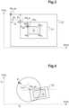
- FIG 2 is a schematic top view of the motor vehicle 1 of the figure 1 , represented in five successive positions located along an avoidance trajectory T1 of an obstacle 15.
- the description of the avoidance trajectory T1 is made in a fixed reference frame (XY).
- the X axis of the reference frame is preferably parallel to the traffic lane 17 of the motor vehicle 1 when the latter is straight. Otherwise, it is preferably tangent to this trajectory at the level of the motor vehicle (at the time when the calculator calculates the avoidance trajectory).
- this X axis is chosen parallel to a ground marking line 23 separating two traffic lanes 21.
- this X axis could be chosen parallel to the axis of movement of the motor vehicle 1, that is to say to the longitudinal axis of the vehicle before the initiation of the avoidance maneuver.
- the Y axis is horizontal and perpendicular to the X axis.
- the initial trajectory T0 of the motor vehicle 10 is shown, as it was followed by the motor vehicle 1 before the detection of the obstacle and the initiation of the avoidance maneuver.
- this initial trajectory T0 is linear and parallel to the ground marking line 23.
- the obstacle 15 is located on the traffic lane 17 of the motor vehicle 1, in front of the latter.
- the obstacle 15 is for example another vehicle, a bicycle, a pedestrian or a static object. This obstacle 15 can therefore be either moving or still.
- Other obstacles 19, 21 may be located in the environment of the motor vehicle 1. In the example considered here, these other obstacles are located on an adjacent traffic lane different from that taken by the motor vehicle 1.
- the computer when it detects an obstacle 15 located on the trajectory of the motor vehicle 1, implements a method for determining an avoidance trajectory T1.
- the detection system 9 acquires data relating to the obstacle 15.
- this obstacle is characterized by the detection system 9 by its shape, its nature, its position relative to the motor vehicle 1 (and in particular its distance from the motor vehicle) and its longitudinal speeds (along the X axis) and lateral speeds (along the Y axis) relative to that of the motor vehicle 1.
- the shape of the obstacle is obtained here by merging data from different sensors. It can thus be defined by a length, a width and a reference point which will then be used in the calculations. As will be well described below, this reference point will be for example the corner of the obstacle closest to the avoidance trajectory.
- the nature of the obstacle can also be obtained by data fusion. As will be well described below, this nature (pedestrian, truck, car ...) will then be used to adjust the safety distance that we wish to keep between the obstacle and the avoidance trajectory (this distance being for example greater for a pedestrian whose behavior is generally more difficult to anticipate).
- the computer 5 detects a potential risk of collision between the motor vehicle 1 and the obstacle 15 on the basis of the acquired data.
- the calculator 5 can use data relating to the motor vehicle 1.
- This data includes, for example, the linear speed of the motor vehicle, the yaw rate of the vehicle, the position of the steering wheel and its angular speed.
- the calculator implements a third step c).
- the calculator 5 acquires the initial position P0 of the motor vehicle 1 at the start of the avoidance maneuver.
- This initial position P0 whose coordinates are noted (X0, Y0), corresponds more precisely to the current position at the present moment of the center of gravity CG of motor vehicle 1 in the frame (X, Y).
- the calculator determines a first final position Pf, the coordinates of which are noted (Xf, Yf), which the motor vehicle 1 must reach at the end of a first part of the avoidance trajectory T1.
- This first part corresponds to the portion of the avoidance trajectory T1 during which the motor vehicle 1 deviates from its initial trajectory T0.
- the second part will correspond to the portion during which the motor vehicle 1 will return to its initial trajectory T0.
- the calculator 5 assigns, for example, to the abscissa Xf a value which corresponds to the abscissa of the current position of the obstacle 15.
- the calculator 5 also assigns to the ordinate Yf a value which is greater than the largest ordinate of the obstacle 15 and which is less than a limit value Ylim.
- This limit value Ylim is determined for example on the basis of data relating to the environment captured by the detection system 9. It may for example be the ordinate of the ground marking line 23, or even the smallest ordinate of the other obstacles 19, 21 present in the environment of the motor vehicle 1 (a safety margin may also be envisaged).
- the computer 5 determines a theoretical impact position Pi, the coordinates of which are noted (Xi, Yi).
- This theoretical impact position Pi corresponds to an extreme position of a safety zone located around the obstacle 15 through which the motor vehicle 1 is not desired to pass in order to avoid the obstacle 15 in complete safety.
- This impact point Pi is therefore the point located on the periphery of this safety zone, at the smallest distance from a predicted avoidance trajectory.
- This impact point is described as theoretical in the sense that there would be no impact between the vehicle and the obstacle if the vehicle passed through this point. It is in fact calculated so as to take into account numerous parameters such as the longitudinal and lateral speeds of the obstacle, the measurement errors of the sensors, etc.
- the abscissa of this theoretical impact position Pi is located between the abscissas of the initial position P0 and the final position Pf.
- the ordinate of this Theoretical impact position Pi is located between the ordinates of the initial position P0 and the final position Pf.
- the detection system 9 determines the coordinates of points of the contour of the obstacle 15 in the (X, Y) frame of reference.
- the data comes from the front camera and/or the telemetry unit of the motor vehicle 1. Here, the data from these two sensors are merged.
- the detection system determines the coordinates of the attachment points Pa1, Pa2, Pa3, Pa4 of the obstacle 15.
- the attachment points Pa1, Pa2, Pa3, Pa4 are “remarkable” points of the obstacle 15 located on the periphery of the latter. These are therefore points that are easily detectable (for example by image processing). For example, in the case of an obstacle 15 formed by a car, the attachment points correspond to the four corners of a rectangle modeling this car.
- the computer 5 determines which of these attachment points will be closest to the motor vehicle 1 during the avoidance maneuver. It does this based on the predicted avoidance trajectory, which indicates whether the motor vehicle will avoid the obstacle to the left or to the right.
- the computer 5 determines whether the obstacle 15 should be avoided to the left or to the right based on the environmental data. For example, if the gap between the obstacle 15 and the road marking 23 is wide enough to allow the motor vehicle 1 to pass between these two elements, then the obstacle can be avoided to the left.
- obstacle 15 is another vehicle that we want to avoid on the left.
- the hook point to avoid is then the left rear corner Pa1 of obstacle 15.
- the point of attachment to be avoided Pa1 has coordinates (X a , Y a ) in the frame (X, Y).
- the avoidance trajectory T1 must pass at a distance from this attachment point Pa1.
- the point of impact Pi is therefore determined according to the position of this attachment point Pa1 but is located at a distance from the latter.
- the measurement errors e x , e y are predetermined and stored in a memory of the computer.
- frame C1 corresponds to the safety zone around obstacle 15 through which it is advisable not to pass in order not to hit obstacle 15, taking into account errors which may have affected the measurements carried out by the detection means 9.
- the computer first determines a time before collision ⁇ which corresponds to the time before impact with obstacle 15 if the motor vehicle does not deviate from its initial trajectory T0.
- frame C2 corresponds to the safety zone around obstacle 15 through which it is advisable not to pass in order not to hit obstacle 15, taking into account errors which may have affected the measurements carried out by detection means 9 and taking into account the speed of obstacle 15.
- the calculator determines the coordinates (Xi, Yi) of the impact point Pi on the basis of the coordinates of the second offset point Pa_ev and according to a minimum safety distance dmin to be respected between the avoidance trajectory T1 and the obstacle 15.
- the minimum safety distance dmin which corresponds to an avoidance radius, is therefore chosen to be greater than or equal to half the greatest width of the vehicle.
- the minimum safety distance dmin can be chosen to be invariable.
- the nature (for example: vehicle, bicycle, pedestrian, etc.) of the obstacle 15 to be avoided which is determined in a known manner on the basis of the data acquired by the detection system 9. It can also depend on other factors such as the road grip. (rain, snow, on ice).
- This minimum safety distance dmin is oriented in relation to the vehicle and therefore in relation to the obstacle, such that it has a longitudinal component along the X axis and a lateral component along the Y axis.
- ⁇ is the angle formed between the X axis and the longitudinal axis of the obstacle 15.
- the computer 5 develops the avoidance trajectory T1. This trajectory is developed so that the vehicle passes through the initial position P0 and through the final position Pf and that it avoids the theoretical impact position Pi from the outside relative to the obstacle (i.e. to the left of the theoretical impact position Pi if the obstacle is avoided from the left, and vice versa).
- f is the polynomial function of the avoidance trajectory
- x the abscissa along the X axis
- N the degree of the polynomial (for example between 4 and 6).
- the calculator 5 seeks to determine the value of the coefficients a i of the polynomial.
- the third constraint is that the avoidance trajectory T1 avoids the theoretical impact position Pi on the desired side, which can be written, for left avoidance: f Xi > Yi or, for a right avoidance f Xi ⁇ Yi
- the fourth constraint is that the first derivative of the avoidance trajectory T1 (which corresponds to the lateral speed of the vehicle) is less than or equal to a first coefficient ⁇ , this condition being expressed according to the formula: dy dx ⁇ ⁇
- the fifth constraint is that the second derivative of the avoidance trajectory T1 (which corresponds to the lateral acceleration of the vehicle) is less than or equal to a second coefficient ⁇ , this condition being expressed according to the formula: d 2 y d 2 x ⁇ ⁇
- the sixth constraint is that the third derivative of the avoidance trajectory T1 (which corresponds to "jerks" in English) is less than or equal to a third coefficient ⁇ , this condition being expressed according to the formula: d 3 y d 3 x ⁇ ⁇
- the two coefficients ⁇ , ⁇ are relative to the controllability limit of the actuators of the system and the vehicle.
- the third coefficient is essentially relating to the comfort felt in the vehicle.
- the values of the three coefficients ⁇ , ⁇ , ⁇ are predetermined, taking into account the dynamic capabilities of the vehicle.
- the resolution of the problem is carried out by means of a convex optimization method, preferably by the method of sums of squares ("Sum Of Squares" in English).
- a convex optimization method preferably by the method of sums of squares ("Sum Of Squares" in English).
- Sums of squares preferably by the method of sums of squares ("Sum Of Squares" in English).
- the fourth constraint is guaranteed if there exist two polynomials P ⁇ 1 (x) and P ⁇ 2 (x), for example of order 2, which are such that: ⁇ ⁇ ⁇ 1 N ia i x i ⁇ 1 ⁇ P ⁇ 1 x X ⁇ 2 ⁇ x ⁇ X ⁇ 2 ⁇ 0 P ⁇ 1 ⁇ 0 P ⁇ 2 ⁇ 0
- the fifth constraint is guaranteed if there exist two polynomials P ⁇ 1 (x) and P ⁇ 2 (x), for example of order 2, which are such that: P ⁇ 1 ⁇ 0 P ⁇ 2 ⁇ 0
- the calculator determines the existence of an avoidance trajectory T1 allowing all six constraints to be met, then the avoidance maneuver can be initiated during a final step.
- the abscissa Xf can be incremented by a predetermined value ⁇ x until the computer finds an avoidance trajectory T1.
- the value of the ordinate Yf of the final position can also be adjusted, for example by incrementing or reducing it, while remaining within the limits detailed above.
- the sixth constraint can be neglected. This constraint is in fact relative to the comfort of the passenger and not to his safety in the sense that it prevents the motor vehicle from changing direction too abruptly in order to avoid a "jolt" which would be unpleasant for the passenger.
- This second method is a convex optimization method by sampling based on a resolution by processing a defined number of problems (or Linear Programming in English), each problem corresponding to the expression of the constraint at a point of the sampling of the points of the avoidance trajectory T1.
- the fifth inequality constraint is satisfied if the second derivative of the polynomial function f satisfies the following equation for all points in the series S x : ⁇ 1 N i i ⁇ 1 has i x i ⁇ 2 ⁇ ⁇
- the sixth inequality constraint is satisfied if the third derivative of the polynomial function f satisfies the following equation for all points in the series S x : ⁇ 1 N i i ⁇ 1 has i x i ⁇ 3 ⁇ ⁇
- the avoidance maneuver can be initiated according to this trajectory.
- This method has a higher number of equations to solve than the sum of squares method. However, all the conditions are linear and are therefore simpler to solve. Therefore, this resolution method can be easily implemented in real time by the computer 5 of the motor vehicle 1.
- the portion of the avoidance trajectory T1 between the initial position P0 and the final position Pf constitutes in practice only a first part of this trajectory.
- the calculation of this second part can begin after the start of the avoidance maneuver, so that this avoidance maneuver can be implemented as quickly as possible.
- second initial position P02 the determination of the initial position of the second part of the avoidance trajectory T1, hereinafter called second initial position P02, is carried out as follows.
- the second initial position P02 would be the same as the final position Pf. However, to avoid returning too quickly to the initial trajectory T0 and hitting the obstacle 15, it is preferable to fix the second initial position P02 at a distance from the final position Pf.
- the abscissa X 02 of the second initial position P02 is chosen to be greater than or equal to the length of the obstacle 15. It is further chosen such that the vehicle has time to stabilize by driving in a straight line for a predetermined duration.
- the ordinate Y 02 of the second initial position P02 is chosen equal to the ordinate of the final position Pf.
- ⁇ stab is the time required for the vehicle to stabilize
- L target is the length of the obstacle
- V is the speed of the motor vehicle 1
- ⁇ x is a predetermined safety margin.
- the parameters ⁇ stab and ⁇ x can be set according to the speed of the motor vehicle
- the choice of the abscissa of the second final position Pf2 is quite free. It can be fixed according to the desired dynamics (sport driving or flexible driving).
- the choice of the second theoretical impact position Pi2 is carried out in the same way as for the impact point Pi, except that the distance from minimum security dmin can optionally be chosen larger.
- obstacles can be simultaneously taken into account, which will generate multiple theoretical impact points, for example fixed obstacles (such as a road edge, a road barrier, a pole, etc.) or mobile obstacles (vehicles on adjacent lanes in the same or opposite direction). These obstacles can be taken into account with or without trajectory prediction. For mobile obstacles, their trajectories can be estimated (for a given duration) in order to adjust the limit value Ylim accordingly.
Landscapes
- Engineering & Computer Science (AREA)
- Automation & Control Theory (AREA)
- Transportation (AREA)
- Mechanical Engineering (AREA)
- Human Computer Interaction (AREA)
- Physics & Mathematics (AREA)
- Mathematical Physics (AREA)
- Control Of Driving Devices And Active Controlling Of Vehicle (AREA)
- Traffic Control Systems (AREA)
- Control Of Position, Course, Altitude, Or Attitude Of Moving Bodies (AREA)
- Steering Control In Accordance With Driving Conditions (AREA)
- Control Of Electric Motors In General (AREA)
Claims (12)
- Verfahren zum Bestimmen einer Ausweichtrajektorie (T1) eines Kraftfahrzeug (1), umfassend die folgenden Schritte:- Erfassen von Daten bezüglich mindestens eines Hindernisses (15), das in dem Umfeld des Kraftfahrzeugs (1) gelegen ist, mittels eines Detektionssystems (9), wobei die Daten einen Abstand zwischen dem Fahrzeug und dem Hindernis umfassen,- Bestimmen einer zu erreichenden finalen Position (Pf) für das Kraftfahrzeug (1) in Abhängigkeit von der Position des Hindernisses (15) und von einer initialen Position (P0) des Kraftfahrzeugs (1),- Berechnen einer theoretischen Kollisionsposition (Pi), die zwischen der initialen Position (P0) und der finalen Position (Pf) gelegen ist, in Abhängigkeit mindestens von einem zu beachtenden Mindestabstand (dmin) zwischen der Ausweichtrajektorie (T1) und dem Hindernis (15), und- Ermitteln der Ausweichtrajektorie (T1) derart, dass das Kraftfahrzeug (1) die initiale Position (P0) und die finale Position (Pf) durchfährt und dass es der theoretischen Kollisionsposition (Pi) außen in Bezug auf das Hindernis (15) ausweicht, dadurch gekennzeichnet, dass die Ausweichtrajektorie (T1) so ermittelt wird, dass ihre Ableitungen, insbesondere die erste, zweite und dritte Ableitung, vorbestimmten Ungleichheitsbedingungen entsprechen.
- Verfahren nach dem vorhergehenden Anspruch, bei dem der mindestens eine minimale Sicherheitsabstand (dmin) in Bezug auf das Kraftfahrzeug (1) so ausgerichtet ist, dass er mindestens eine Längskomponente bezogen auf die Längsachse des Kraftfahrzeugs (1) und bevorzugt auch eine seitliche Komponente aufweist.
- Verfahren nach einem der vorhergehenden Ansprüche, bei dem, zum Bestimmen der theoretischen Kollisionsposition (Pi), vorgesehen ist:- die Position eines ersten Punkts (Pa1) des Hindernisses, der zu einer voraussichtlichen Ausweichtrajektorie nächstgelegen ist, auf der Grundlage der von dem Detektionssystem (9) erfassten Daten zu bestimmen, und- die theoretische Kollisionsposition (Pi) in Abhängigkeit von der Position des ersten Punkts (Pa1) , von dem Mindestabstand (dmin) und von mindestens einem weiteren Datenelement abzuleiten.
- Verfahren nach dem vorhergehenden Anspruch, bei dem das andere Datenelement der folgenden Liste angehört:- eine vorbestimmte Unsicherheit des Detektionssystems (9),- die Art des Hindernisses (15) und- die relative Geschwindigkeit des Hindernisses (15) in Bezug auf das Kraftfahrzeug (1) und gegebenenfalls auch seine Richtung.
- Verfahren nach dem vorhergehenden Anspruch, bei dem vorgesehen ist, einen Sicherheitsbereich um das mindestens eine Hindernis (15) herum in Abhängigkeit von dem Mindestabstand (dmin) und gegebenenfalls auch von dem mindestens einen weiteren Datenelement zu bestimmen.
- Verfahren nach einem der beiden vorhergehenden Ansprüche, bei dem, zum Bestimmen der Position des Kollisionspunkts , vorgesehen ist:- die relativen Längs- und Seitengeschwindigkeiten des Hindernisses (15) in Bezug auf das Kraftfahrzeug (1) zu bestimmen,- daraus eine Zeit vor einer theoretischen Kollision zwischen dem Kraftfahrzeug (1) und dem Hindernis (15) abzuleiten,- die Position des Hindernisses (15) zu einer späteren Zeit zu bestimmen, die der Zeit vor der theoretischen Kollision entspricht, und- daraus die theoretische Kollisionsposition (Pi) abzuleiten.
- Verfahren nach dem vorhergehenden Anspruch, bei dem der Schritt des Bestimmens der Position des Hindernisses (15) nur durchgeführt wird, wenn die Zeit vor der theoretischen Kollision kürzer als ein vorbestimmter Schwellenwert ist.
- Verfahren nach einem der vorhergehenden Ansprüche, bei dem die Ausweichtrajektorie (T1) so ermittelt wird, dass sie eine Bedingung erfüllt, die sich auf das Durchfahren der Ausweichtrajektorie (T1) außerhalb der theoretischen Kollisionsposition (Pi) bezieht.
- Verfahren nach dem vorhergehenden Anspruch, bei dem, wenn keine Ausweichtrajektorie (T1), deren Ableitungen die Ungleichheitsbedingungen erfüllen, gefunden wird, ein Schritt des Anpassens der finalen Position (Pf) des Kraftfahrzeugs (1) und dann ein neuer Schritt des Ermittelns der Ausweichtrajektorie (T1) vorgesehen ist.
- Verfahren nach einem der beiden vorhergehenden Ansprüche, bei dem die Ausweichtrajektorie (T1) mittels einer Methode der konvexen Optimierung ermittelt wird, insbesondere durch eine Methode der Summe der Quadrate oder durch Sampling.
- Verfahren nach einem der Ansprüche 1 bis 10, bei dem, wenn das Kraftfahrzeug (1) bei seinem Eintreffen an der initialen Position (P0) gemäß einer initialen Trajektorie (T0) fährt, ein Vorgang des Bestimmens eines zweiten Teils der Ausweichtrajektorie (T1) vorgesehen ist, der die Rückkehr des Kraftfahrzeugs (1) auf die initiale Trajektorie (T0) ermöglicht, der die folgenden Schritte umfasst:- Bestimmen einer zweiten finalen Position (Pf2) in Abhängigkeit von der Position des mindestens einen Hindernisses (15) in Bezug auf das Kraftfahrzeug (1) und in Abhängigkeit von der finalen Position (Pf),- Bestimmen einer zweiten theoretischen Kollisionsposition (Pi2), die zwischen der finalen Position (Pf) und der zweiten finalen Position (Pf2) gelegen ist, in Abhängigkeit mindestens von einem zu beachtenden Mindestabstand zwischen der Ausweichtrajektorie (T1) und dem Hindernis (15), und- Bestimmen des zweiten Teils der Ausweichtrajektorie (T1) so, dass das Kraftfahrzeug (1) die zweite finale Position (Pf2) durchfährt und der zweiten theoretischen Kollisionsposition (Pi2) außen in Bezug auf das Hindernis (15) ausweicht.
- System zur Bestimmung einer Ausweichtrajektorie eines Kraftfahrzeugs, umfassend:- ein Detektionssystem (9), das geeignet ist, Daten bezüglich eines Hindernisses (15) zu erfassen, das im Umfeld des Kraftfahrzeugs (1) gelegen ist, und- einen Rechner (5), der dazu ausgestaltet ist, ein Verfahren nach einem der vorhergehenden Ansprüche durchzuführen.
Applications Claiming Priority (2)
| Application Number | Priority Date | Filing Date | Title |
|---|---|---|---|
| FR1907351A FR3098172B1 (fr) | 2019-07-02 | 2019-07-02 | Procédé de détermination d’une trajectoire d’évitement d’un véhicule automobile |
| PCT/EP2020/065449 WO2021001112A1 (fr) | 2019-07-02 | 2020-06-04 | Procede de determination d'une trajectoire d'evitement d'un vehicule automobile |
Publications (2)
| Publication Number | Publication Date |
|---|---|
| EP3994042A1 EP3994042A1 (de) | 2022-05-11 |
| EP3994042B1 true EP3994042B1 (de) | 2024-11-06 |
Family
ID=68654628
Family Applications (1)
| Application Number | Title | Priority Date | Filing Date |
|---|---|---|---|
| EP20730269.6A Active EP3994042B1 (de) | 2019-07-02 | 2020-06-04 | Verfahren zur bestimmung eines ausweichweges eines kraftfahrzeuges |
Country Status (6)
| Country | Link |
|---|---|
| US (1) | US12037014B2 (de) |
| EP (1) | EP3994042B1 (de) |
| JP (1) | JP7315039B2 (de) |
| CN (1) | CN114302839B (de) |
| FR (1) | FR3098172B1 (de) |
| WO (1) | WO2021001112A1 (de) |
Families Citing this family (8)
| Publication number | Priority date | Publication date | Assignee | Title |
|---|---|---|---|---|
| US11904890B2 (en) * | 2020-06-17 | 2024-02-20 | Baidu Usa Llc | Lane change system for lanes with different speed limits |
| US11738772B1 (en) * | 2020-12-18 | 2023-08-29 | Zoox, Inc. | Object avoidance with perceived safety subgoal |
| FR3120039B1 (fr) * | 2021-02-19 | 2025-09-26 | Renault Sas | Procédé d’évitement d’obstacles |
| US20220315047A1 (en) * | 2021-03-30 | 2022-10-06 | Honda Research Institute Europe Gmbh | Method, system and vehicle with an uncertainty-based lane positioning control |
| FR3123862B1 (fr) * | 2021-06-11 | 2023-04-28 | Psa Automobiles Sa | Procédé et dispositif de contrôle d’un véhicule autonome |
| FR3125785B1 (fr) * | 2021-07-27 | 2024-01-19 | Renault Sas | Procédé de pilotage de véhicule et d’évitement d’obstacle |
| US12091003B1 (en) * | 2021-08-31 | 2024-09-17 | Zoox, Inc. | Collision avoidance for a vehicle with objects in an oncoming lane |
| EP4318162B1 (de) * | 2022-05-23 | 2025-07-02 | Beijing Xiaomi Robot Technology Co., Ltd. | Mobile vorrichtung und geschwindigkeitssteuerungsverfahren und -vorrichtung dafür sowie speichermedium |
Family Cites Families (16)
| Publication number | Priority date | Publication date | Assignee | Title |
|---|---|---|---|---|
| DE102005003274A1 (de) * | 2005-01-25 | 2006-07-27 | Robert Bosch Gmbh | Verfahren und Vorrichtung zur Vermeidung und/oder Minderung der Folgen von Kollisionen beim Ausweichen vor Hindernissen |
| EP2549456B1 (de) * | 2010-03-16 | 2020-05-06 | Toyota Jidosha Kabushiki Kaisha | Fahrhilfe |
| DE102012017628A1 (de) * | 2012-09-06 | 2014-03-06 | Volkswagen Aktiengesellschaft | Verfahren zur Steuerung eines Fahrzeugs und Fahrerassistenzsystem |
| DE102013009252A1 (de) | 2013-06-03 | 2014-12-04 | Trw Automotive Gmbh | Steuergerät und Verfahren für eine Notfall-Lenkunterstützungsfunktion |
| DE102013010004A1 (de) | 2013-06-14 | 2014-12-18 | Valeo Schalter Und Sensoren Gmbh | Verfahren und Vorrichtung zum Ausführen von kollisionsvermeidenden Maßnahmen |
| DE102014206341A1 (de) * | 2014-04-02 | 2015-10-08 | Bayerische Motoren Werke Aktiengesellschaft | Ausweichassistent |
| US9227632B1 (en) | 2014-08-29 | 2016-01-05 | GM Global Technology Operations LLC | Method of path planning for evasive steering maneuver |
| DE102014017594A1 (de) * | 2014-11-27 | 2016-06-02 | GM Global Technology Operations LLC (n. d. Ges. d. Staates Delaware) | Verfahren zur Durchführung eines Ausweichmanövers, Computerprogrammprodukt sowie Kraftfahrzeug |
| JP6637400B2 (ja) * | 2016-10-12 | 2020-01-29 | 本田技研工業株式会社 | 車両制御装置 |
| JP6520905B2 (ja) * | 2016-12-19 | 2019-05-29 | トヨタ自動車株式会社 | 車両用運転支援装置 |
| JP6547735B2 (ja) * | 2016-12-22 | 2019-07-24 | トヨタ自動車株式会社 | 衝突回避支援装置 |
| US10446031B2 (en) * | 2017-03-14 | 2019-10-15 | Hyundai Mobis Co., Ltd. | Apparatus and method of safety support for vehicle |
| US10571921B2 (en) * | 2017-09-18 | 2020-02-25 | Baidu Usa Llc | Path optimization based on constrained smoothing spline for autonomous driving vehicles |
| KR102591198B1 (ko) * | 2018-09-28 | 2023-10-20 | 현대자동차주식회사 | 차량 및 차량의 제어방법 |
| CN109664881A (zh) * | 2019-01-08 | 2019-04-23 | 广州小鹏汽车科技有限公司 | 一种紧急转向辅助驾驶方法、系统及电子设备 |
| KR102817578B1 (ko) * | 2019-03-05 | 2025-06-11 | 현대자동차주식회사 | 차량 안전주행 지원 장치 및 방법 |
-
2019
- 2019-07-02 FR FR1907351A patent/FR3098172B1/fr active Active
-
2020
- 2020-06-04 EP EP20730269.6A patent/EP3994042B1/de active Active
- 2020-06-04 CN CN202080048442.7A patent/CN114302839B/zh active Active
- 2020-06-04 WO PCT/EP2020/065449 patent/WO2021001112A1/fr not_active Ceased
- 2020-06-04 US US17/621,307 patent/US12037014B2/en active Active
- 2020-06-04 JP JP2021577150A patent/JP7315039B2/ja active Active
Also Published As
| Publication number | Publication date |
|---|---|
| US20220355820A1 (en) | 2022-11-10 |
| WO2021001112A1 (fr) | 2021-01-07 |
| JP7315039B2 (ja) | 2023-07-26 |
| FR3098172A1 (fr) | 2021-01-08 |
| CN114302839B (zh) | 2024-09-20 |
| US12037014B2 (en) | 2024-07-16 |
| EP3994042A1 (de) | 2022-05-11 |
| CN114302839A (zh) | 2022-04-08 |
| FR3098172B1 (fr) | 2022-08-12 |
| JP2022538277A (ja) | 2022-09-01 |
Similar Documents
| Publication | Publication Date | Title |
|---|---|---|
| EP3994042B1 (de) | Verfahren zur bestimmung eines ausweichweges eines kraftfahrzeuges | |
| EP3938260B1 (de) | Verfahren zur erzeugung eines sollwertes für die kombinierte regelung eines radlenksystems und eines differentialbremssystems eines kraftfahrzeuges | |
| EP3356204B1 (de) | System zur steuerung der lenkmittel eines kraftfahrzeugs im falle einer drohenden kollision mit einem hindernis | |
| EP1892688B1 (de) | Verfahren zur Bestimmung der Durchfahrt eines Fahrzeugs durch eine engen Durchlass | |
| EP4025468B1 (de) | Vorrichtung zur prädiktiven steuerung der bewegung eines kraftfahrzeugs | |
| EP4294688B1 (de) | Verfahren zum aktivieren eines hindernisvermeidungssystems für ein kraftfahrzeug | |
| FR3104107A1 (fr) | Procédé de pilotage d’un véhicule automobile | |
| WO2019162238A1 (fr) | Dispositif et procédé d'aide à la conduite d'un véhicule automobile | |
| EP4402030A1 (de) | Verfahren zur vermeidung von hindernissen | |
| EP4157689B1 (de) | Fahrerassistenzverfahren mit virtuellem ziel für adaptive geschwindigkeitsregelung | |
| EP4223604A1 (de) | Verfahren zur gefahrenerkennung in der umgebung eines kraftfahrzeugs | |
| EP4445346A1 (de) | Verfahren zur unterstützung der spurhaltung eines fahrzeugs bei einer spurverengung oder -verbreiterung | |
| FR3092914A1 (fr) | Procédé de détermination de la trajectoire d'un véhicule comprenant quatre roues directrices | |
| FR3062360A1 (fr) | Procede d'aide a la conduite d'un vehicule automobile et vehicule automobile correspondant | |
| EP4227912A1 (de) | Verfahren zur erkennung einer mittellinie eines verkehrsweges | |
| EP3338260B1 (de) | Verfahren zur bestimmung des aufmerksamkeitsgrades eines fahrers eines kraftfahrzeugs und verfahren zur stimulierung der aufmerksamkeit eines fahrers eines kraftfahrzeugs | |
| EP3377386B1 (de) | Fahrerassistenzverfahren für ein kraftfahrzeug | |
| EP4284690B1 (de) | Verfahren zur vermeidung von hindernissen | |
| FR3150002A1 (fr) | Procédé de caractérisation d’une posture d’un objet mobile se déplaçant sur un axe de circulation | |
| FR3142151A1 (fr) | Procédé de caractérisation de lignes de bord de voie en vue du pilotage d’un véhicule automobile | |
| FR3146300A1 (fr) | procédé de pilotage d’un véhicule automobile | |
| FR3142730A1 (fr) | Procédé de détection d’une ligne centrale d’une voie de circulation et de pilotage d’un véhicule automobile | |
| FR3135048A1 (fr) | Procédé de suivi d’au moins une limite de bord de voie de circulation et véhicule automobile associé | |
| WO2024110258A1 (fr) | Procede d'assistance au pilotage d'un vehicule automobile pour le realigner parallelement a une trajectoire ideale, dispositif et vehicule associes | |
| EP4382382A1 (de) | Verfahren zur steuerung eines fahrzeugs im fahrweg |
Legal Events
| Date | Code | Title | Description |
|---|---|---|---|
| STAA | Information on the status of an ep patent application or granted ep patent |
Free format text: STATUS: UNKNOWN |
|
| STAA | Information on the status of an ep patent application or granted ep patent |
Free format text: STATUS: THE INTERNATIONAL PUBLICATION HAS BEEN MADE |
|
| PUAI | Public reference made under article 153(3) epc to a published international application that has entered the european phase |
Free format text: ORIGINAL CODE: 0009012 |
|
| STAA | Information on the status of an ep patent application or granted ep patent |
Free format text: STATUS: REQUEST FOR EXAMINATION WAS MADE |
|
| 17P | Request for examination filed |
Effective date: 20211220 |
|
| AK | Designated contracting states |
Kind code of ref document: A1 Designated state(s): AL AT BE BG CH CY CZ DE DK EE ES FI FR GB GR HR HU IE IS IT LI LT LU LV MC MK MT NL NO PL PT RO RS SE SI SK SM TR |
|
| RAP3 | Party data changed (applicant data changed or rights of an application transferred) |
Owner name: NISSAN MOTOR CO., LTD. Owner name: RENAULT S.A.S |
|
| DAV | Request for validation of the european patent (deleted) | ||
| DAX | Request for extension of the european patent (deleted) | ||
| RAP1 | Party data changed (applicant data changed or rights of an application transferred) |
Owner name: NISSAN MOTOR CO., LTD. Owner name: AMPERE SAS |
|
| GRAP | Despatch of communication of intention to grant a patent |
Free format text: ORIGINAL CODE: EPIDOSNIGR1 |
|
| STAA | Information on the status of an ep patent application or granted ep patent |
Free format text: STATUS: GRANT OF PATENT IS INTENDED |
|
| RIC1 | Information provided on ipc code assigned before grant |
Ipc: B60W 30/095 20120101ALI20240514BHEP Ipc: B60W 50/00 20060101ALI20240514BHEP Ipc: G05D 1/00 20060101ALI20240514BHEP Ipc: B60W 30/09 20120101AFI20240514BHEP |
|
| INTG | Intention to grant announced |
Effective date: 20240531 |
|
| GRAS | Grant fee paid |
Free format text: ORIGINAL CODE: EPIDOSNIGR3 |
|
| GRAA | (expected) grant |
Free format text: ORIGINAL CODE: 0009210 |
|
| STAA | Information on the status of an ep patent application or granted ep patent |
Free format text: STATUS: THE PATENT HAS BEEN GRANTED |
|
| AK | Designated contracting states |
Kind code of ref document: B1 Designated state(s): AL AT BE BG CH CY CZ DE DK EE ES FI FR GB GR HR HU IE IS IT LI LT LU LV MC MK MT NL NO PL PT RO RS SE SI SK SM TR |
|
| REG | Reference to a national code |
Ref country code: GB Ref legal event code: FG4D Free format text: NOT ENGLISH |
|
| REG | Reference to a national code |
Ref country code: CH Ref legal event code: EP |
|
| REG | Reference to a national code |
Ref country code: DE Ref legal event code: R096 Ref document number: 602020040808 Country of ref document: DE |
|
| REG | Reference to a national code |
Ref country code: IE Ref legal event code: FG4D Free format text: LANGUAGE OF EP DOCUMENT: FRENCH |
|
| REG | Reference to a national code |
Ref country code: LT Ref legal event code: MG9D |
|
| REG | Reference to a national code |
Ref country code: NL Ref legal event code: MP Effective date: 20241106 |
|
| PG25 | Lapsed in a contracting state [announced via postgrant information from national office to epo] |
Ref country code: IS Free format text: LAPSE BECAUSE OF FAILURE TO SUBMIT A TRANSLATION OF THE DESCRIPTION OR TO PAY THE FEE WITHIN THE PRESCRIBED TIME-LIMIT Effective date: 20250306 Ref country code: HR Free format text: LAPSE BECAUSE OF FAILURE TO SUBMIT A TRANSLATION OF THE DESCRIPTION OR TO PAY THE FEE WITHIN THE PRESCRIBED TIME-LIMIT Effective date: 20241106 Ref country code: PT Free format text: LAPSE BECAUSE OF FAILURE TO SUBMIT A TRANSLATION OF THE DESCRIPTION OR TO PAY THE FEE WITHIN THE PRESCRIBED TIME-LIMIT Effective date: 20250306 |
|
| PG25 | Lapsed in a contracting state [announced via postgrant information from national office to epo] |
Ref country code: FI Free format text: LAPSE BECAUSE OF FAILURE TO SUBMIT A TRANSLATION OF THE DESCRIPTION OR TO PAY THE FEE WITHIN THE PRESCRIBED TIME-LIMIT Effective date: 20241106 Ref country code: NL Free format text: LAPSE BECAUSE OF FAILURE TO SUBMIT A TRANSLATION OF THE DESCRIPTION OR TO PAY THE FEE WITHIN THE PRESCRIBED TIME-LIMIT Effective date: 20241106 |
|
| REG | Reference to a national code |
Ref country code: AT Ref legal event code: MK05 Ref document number: 1739064 Country of ref document: AT Kind code of ref document: T Effective date: 20241106 |
|
| PG25 | Lapsed in a contracting state [announced via postgrant information from national office to epo] |
Ref country code: BG Free format text: LAPSE BECAUSE OF FAILURE TO SUBMIT A TRANSLATION OF THE DESCRIPTION OR TO PAY THE FEE WITHIN THE PRESCRIBED TIME-LIMIT Effective date: 20241106 |
|
| PG25 | Lapsed in a contracting state [announced via postgrant information from national office to epo] |
Ref country code: ES Free format text: LAPSE BECAUSE OF FAILURE TO SUBMIT A TRANSLATION OF THE DESCRIPTION OR TO PAY THE FEE WITHIN THE PRESCRIBED TIME-LIMIT Effective date: 20241106 |
|
| PG25 | Lapsed in a contracting state [announced via postgrant information from national office to epo] |
Ref country code: NO Free format text: LAPSE BECAUSE OF FAILURE TO SUBMIT A TRANSLATION OF THE DESCRIPTION OR TO PAY THE FEE WITHIN THE PRESCRIBED TIME-LIMIT Effective date: 20250206 |
|
| PG25 | Lapsed in a contracting state [announced via postgrant information from national office to epo] |
Ref country code: LV Free format text: LAPSE BECAUSE OF FAILURE TO SUBMIT A TRANSLATION OF THE DESCRIPTION OR TO PAY THE FEE WITHIN THE PRESCRIBED TIME-LIMIT Effective date: 20241106 Ref country code: GR Free format text: LAPSE BECAUSE OF FAILURE TO SUBMIT A TRANSLATION OF THE DESCRIPTION OR TO PAY THE FEE WITHIN THE PRESCRIBED TIME-LIMIT Effective date: 20250207 Ref country code: AT Free format text: LAPSE BECAUSE OF FAILURE TO SUBMIT A TRANSLATION OF THE DESCRIPTION OR TO PAY THE FEE WITHIN THE PRESCRIBED TIME-LIMIT Effective date: 20241106 |
|
| PG25 | Lapsed in a contracting state [announced via postgrant information from national office to epo] |
Ref country code: PL Free format text: LAPSE BECAUSE OF FAILURE TO SUBMIT A TRANSLATION OF THE DESCRIPTION OR TO PAY THE FEE WITHIN THE PRESCRIBED TIME-LIMIT Effective date: 20241106 |
|
| PG25 | Lapsed in a contracting state [announced via postgrant information from national office to epo] |
Ref country code: RS Free format text: LAPSE BECAUSE OF FAILURE TO SUBMIT A TRANSLATION OF THE DESCRIPTION OR TO PAY THE FEE WITHIN THE PRESCRIBED TIME-LIMIT Effective date: 20250206 |
|
| PG25 | Lapsed in a contracting state [announced via postgrant information from national office to epo] |
Ref country code: SM Free format text: LAPSE BECAUSE OF FAILURE TO SUBMIT A TRANSLATION OF THE DESCRIPTION OR TO PAY THE FEE WITHIN THE PRESCRIBED TIME-LIMIT Effective date: 20241106 |
|
| PGFP | Annual fee paid to national office [announced via postgrant information from national office to epo] |
Ref country code: DE Payment date: 20250618 Year of fee payment: 6 |
|
| PG25 | Lapsed in a contracting state [announced via postgrant information from national office to epo] |
Ref country code: DK Free format text: LAPSE BECAUSE OF FAILURE TO SUBMIT A TRANSLATION OF THE DESCRIPTION OR TO PAY THE FEE WITHIN THE PRESCRIBED TIME-LIMIT Effective date: 20241106 |
|
| PGFP | Annual fee paid to national office [announced via postgrant information from national office to epo] |
Ref country code: GB Payment date: 20250618 Year of fee payment: 6 |
|
| PG25 | Lapsed in a contracting state [announced via postgrant information from national office to epo] |
Ref country code: EE Free format text: LAPSE BECAUSE OF FAILURE TO SUBMIT A TRANSLATION OF THE DESCRIPTION OR TO PAY THE FEE WITHIN THE PRESCRIBED TIME-LIMIT Effective date: 20241106 |
|
| PGFP | Annual fee paid to national office [announced via postgrant information from national office to epo] |
Ref country code: FR Payment date: 20250627 Year of fee payment: 6 |
|
| PG25 | Lapsed in a contracting state [announced via postgrant information from national office to epo] |
Ref country code: RO Free format text: LAPSE BECAUSE OF FAILURE TO SUBMIT A TRANSLATION OF THE DESCRIPTION OR TO PAY THE FEE WITHIN THE PRESCRIBED TIME-LIMIT Effective date: 20241106 |
|
| PG25 | Lapsed in a contracting state [announced via postgrant information from national office to epo] |
Ref country code: SK Free format text: LAPSE BECAUSE OF FAILURE TO SUBMIT A TRANSLATION OF THE DESCRIPTION OR TO PAY THE FEE WITHIN THE PRESCRIBED TIME-LIMIT Effective date: 20241106 |
|
| PG25 | Lapsed in a contracting state [announced via postgrant information from national office to epo] |
Ref country code: CZ Free format text: LAPSE BECAUSE OF FAILURE TO SUBMIT A TRANSLATION OF THE DESCRIPTION OR TO PAY THE FEE WITHIN THE PRESCRIBED TIME-LIMIT Effective date: 20241106 |
|
| PG25 | Lapsed in a contracting state [announced via postgrant information from national office to epo] |
Ref country code: IT Free format text: LAPSE BECAUSE OF FAILURE TO SUBMIT A TRANSLATION OF THE DESCRIPTION OR TO PAY THE FEE WITHIN THE PRESCRIBED TIME-LIMIT Effective date: 20241106 |
|
| REG | Reference to a national code |
Ref country code: DE Ref legal event code: R097 Ref document number: 602020040808 Country of ref document: DE |
|
| PG25 | Lapsed in a contracting state [announced via postgrant information from national office to epo] |
Ref country code: SE Free format text: LAPSE BECAUSE OF FAILURE TO SUBMIT A TRANSLATION OF THE DESCRIPTION OR TO PAY THE FEE WITHIN THE PRESCRIBED TIME-LIMIT Effective date: 20241106 |
|
| PLBE | No opposition filed within time limit |
Free format text: ORIGINAL CODE: 0009261 |
|
| STAA | Information on the status of an ep patent application or granted ep patent |
Free format text: STATUS: NO OPPOSITION FILED WITHIN TIME LIMIT |
|
| 26N | No opposition filed |
Effective date: 20250807 |
|
| REG | Reference to a national code |
Ref country code: CH Ref legal event code: H13 Free format text: ST27 STATUS EVENT CODE: U-0-0-H10-H13 (AS PROVIDED BY THE NATIONAL OFFICE) Effective date: 20260127 |
|
| PG25 | Lapsed in a contracting state [announced via postgrant information from national office to epo] |
Ref country code: MC Free format text: LAPSE BECAUSE OF FAILURE TO SUBMIT A TRANSLATION OF THE DESCRIPTION OR TO PAY THE FEE WITHIN THE PRESCRIBED TIME-LIMIT Effective date: 20241106 |
|
| PG25 | Lapsed in a contracting state [announced via postgrant information from national office to epo] |
Ref country code: LU Free format text: LAPSE BECAUSE OF NON-PAYMENT OF DUE FEES Effective date: 20250604 |
|
| REG | Reference to a national code |
Ref country code: BE Ref legal event code: MM Effective date: 20250630 |
|
| PG25 | Lapsed in a contracting state [announced via postgrant information from national office to epo] |
Ref country code: IE Free format text: LAPSE BECAUSE OF NON-PAYMENT OF DUE FEES Effective date: 20250604 |
|
| PG25 | Lapsed in a contracting state [announced via postgrant information from national office to epo] |
Ref country code: BE Free format text: LAPSE BECAUSE OF NON-PAYMENT OF DUE FEES Effective date: 20250630 |
|
| PG25 | Lapsed in a contracting state [announced via postgrant information from national office to epo] |
Ref country code: CH Free format text: LAPSE BECAUSE OF NON-PAYMENT OF DUE FEES Effective date: 20250630 |