EP3994321B1 - Pince de tube d'échafaudage - Google Patents
Pince de tube d'échafaudage Download PDFInfo
- Publication number
- EP3994321B1 EP3994321B1 EP20834684.1A EP20834684A EP3994321B1 EP 3994321 B1 EP3994321 B1 EP 3994321B1 EP 20834684 A EP20834684 A EP 20834684A EP 3994321 B1 EP3994321 B1 EP 3994321B1
- Authority
- EP
- European Patent Office
- Prior art keywords
- bolt
- base
- scaffolding
- clamp
- scaffolding tube
- Prior art date
- Legal status (The legal status is an assumption and is not a legal conclusion. Google has not performed a legal analysis and makes no representation as to the accuracy of the status listed.)
- Active
Links
Images

















Classifications
-
- E—FIXED CONSTRUCTIONS
- E04—BUILDING
- E04G—SCAFFOLDING; FORMS; SHUTTERING; BUILDING IMPLEMENTS OR AIDS, OR THEIR USE; HANDLING BUILDING MATERIALS ON THE SITE; REPAIRING, BREAKING-UP OR OTHER WORK ON EXISTING BUILDINGS
- E04G1/00—Scaffolds primarily resting on the ground
- E04G1/02—Scaffolds primarily resting on the ground composed essentially of members elongated in one dimension [1D] only, e.g. poles, lattice masts, with or without end portions of special form, connected together by any means
- E04G1/04—Scaffolds primarily resting on the ground composed essentially of members elongated in one dimension [1D] only, e.g. poles, lattice masts, with or without end portions of special form, connected together by any means the members being exclusively poles, rods, beams, or other members of similar form and simple cross-section
-
- E—FIXED CONSTRUCTIONS
- E04—BUILDING
- E04G—SCAFFOLDING; FORMS; SHUTTERING; BUILDING IMPLEMENTS OR AIDS, OR THEIR USE; HANDLING BUILDING MATERIALS ON THE SITE; REPAIRING, BREAKING-UP OR OTHER WORK ON EXISTING BUILDINGS
- E04G7/00—Connections between parts of the scaffold
- E04G7/02—Connections between parts of the scaffold with separate coupling elements
- E04G7/06—Stiff scaffolding clamps for connecting scaffold members of common shape
- E04G7/12—Clamps or clips for crossing members
- E04G7/14—Clamps or clips for crossing members for clamping the members independently
-
- E—FIXED CONSTRUCTIONS
- E04—BUILDING
- E04G—SCAFFOLDING; FORMS; SHUTTERING; BUILDING IMPLEMENTS OR AIDS, OR THEIR USE; HANDLING BUILDING MATERIALS ON THE SITE; REPAIRING, BREAKING-UP OR OTHER WORK ON EXISTING BUILDINGS
- E04G7/00—Connections between parts of the scaffold
- E04G7/02—Connections between parts of the scaffold with separate coupling elements
- E04G7/06—Stiff scaffolding clamps for connecting scaffold members of common shape
- E04G7/12—Clamps or clips for crossing members
- E04G7/14—Clamps or clips for crossing members for clamping the members independently
- E04G7/16—Clamps or clips for crossing members for clamping the members independently of which the clamping parts for the different members are rotatable with respect to one another
-
- F—MECHANICAL ENGINEERING; LIGHTING; HEATING; WEAPONS; BLASTING
- F16—ENGINEERING ELEMENTS AND UNITS; GENERAL MEASURES FOR PRODUCING AND MAINTAINING EFFECTIVE FUNCTIONING OF MACHINES OR INSTALLATIONS; THERMAL INSULATION IN GENERAL
- F16B—DEVICES FOR FASTENING OR SECURING CONSTRUCTIONAL ELEMENTS OR MACHINE PARTS TOGETHER, e.g. NAILS, BOLTS, CIRCLIPS, CLAMPS, CLIPS OR WEDGES; JOINTS OR JOINTING
- F16B2/00—Friction-grip releasable fastenings
- F16B2/02—Clamps, i.e. with gripping action effected by positive means other than the inherent resistance to deformation of the material of the fastening
- F16B2/06—Clamps, i.e. with gripping action effected by positive means other than the inherent resistance to deformation of the material of the fastening external, i.e. with contracting action
- F16B2/10—Clamps, i.e. with gripping action effected by positive means other than the inherent resistance to deformation of the material of the fastening external, i.e. with contracting action using pivoting jaws
-
- F—MECHANICAL ENGINEERING; LIGHTING; HEATING; WEAPONS; BLASTING
- F16—ENGINEERING ELEMENTS AND UNITS; GENERAL MEASURES FOR PRODUCING AND MAINTAINING EFFECTIVE FUNCTIONING OF MACHINES OR INSTALLATIONS; THERMAL INSULATION IN GENERAL
- F16B—DEVICES FOR FASTENING OR SECURING CONSTRUCTIONAL ELEMENTS OR MACHINE PARTS TOGETHER, e.g. NAILS, BOLTS, CIRCLIPS, CLAMPS, CLIPS OR WEDGES; JOINTS OR JOINTING
- F16B2/00—Friction-grip releasable fastenings
- F16B2/02—Clamps, i.e. with gripping action effected by positive means other than the inherent resistance to deformation of the material of the fastening
- F16B2/14—Clamps, i.e. with gripping action effected by positive means other than the inherent resistance to deformation of the material of the fastening using wedges
-
- F—MECHANICAL ENGINEERING; LIGHTING; HEATING; WEAPONS; BLASTING
- F16—ENGINEERING ELEMENTS AND UNITS; GENERAL MEASURES FOR PRODUCING AND MAINTAINING EFFECTIVE FUNCTIONING OF MACHINES OR INSTALLATIONS; THERMAL INSULATION IN GENERAL
- F16B—DEVICES FOR FASTENING OR SECURING CONSTRUCTIONAL ELEMENTS OR MACHINE PARTS TOGETHER, e.g. NAILS, BOLTS, CIRCLIPS, CLAMPS, CLIPS OR WEDGES; JOINTS OR JOINTING
- F16B2/00—Friction-grip releasable fastenings
- F16B2/02—Clamps, i.e. with gripping action effected by positive means other than the inherent resistance to deformation of the material of the fastening
- F16B2/18—Clamps, i.e. with gripping action effected by positive means other than the inherent resistance to deformation of the material of the fastening using cams, levers, eccentrics, or toggles
- F16B2/185—Clamps, i.e. with gripping action effected by positive means other than the inherent resistance to deformation of the material of the fastening using cams, levers, eccentrics, or toggles using levers
-
- F—MECHANICAL ENGINEERING; LIGHTING; HEATING; WEAPONS; BLASTING
- F16—ENGINEERING ELEMENTS AND UNITS; GENERAL MEASURES FOR PRODUCING AND MAINTAINING EFFECTIVE FUNCTIONING OF MACHINES OR INSTALLATIONS; THERMAL INSULATION IN GENERAL
- F16B—DEVICES FOR FASTENING OR SECURING CONSTRUCTIONAL ELEMENTS OR MACHINE PARTS TOGETHER, e.g. NAILS, BOLTS, CIRCLIPS, CLAMPS, CLIPS OR WEDGES; JOINTS OR JOINTING
- F16B21/00—Means for preventing relative axial movement of a pin, spigot, shaft or the like and a member surrounding it; Stud-and-socket releasable fastenings
- F16B21/02—Releasable fastening devices locking by rotation
-
- F—MECHANICAL ENGINEERING; LIGHTING; HEATING; WEAPONS; BLASTING
- F16—ENGINEERING ELEMENTS AND UNITS; GENERAL MEASURES FOR PRODUCING AND MAINTAINING EFFECTIVE FUNCTIONING OF MACHINES OR INSTALLATIONS; THERMAL INSULATION IN GENERAL
- F16B—DEVICES FOR FASTENING OR SECURING CONSTRUCTIONAL ELEMENTS OR MACHINE PARTS TOGETHER, e.g. NAILS, BOLTS, CIRCLIPS, CLAMPS, CLIPS OR WEDGES; JOINTS OR JOINTING
- F16B5/00—Joining sheets or plates, e.g. panels, to one another or to strips or bars parallel to them
- F16B5/02—Joining sheets or plates, e.g. panels, to one another or to strips or bars parallel to them by means of fastening members using screw-thread
- F16B5/0275—Joining sheets or plates, e.g. panels, to one another or to strips or bars parallel to them by means of fastening members using screw-thread the screw-threaded element having at least two axially separated threaded portions
-
- F—MECHANICAL ENGINEERING; LIGHTING; HEATING; WEAPONS; BLASTING
- F16—ENGINEERING ELEMENTS AND UNITS; GENERAL MEASURES FOR PRODUCING AND MAINTAINING EFFECTIVE FUNCTIONING OF MACHINES OR INSTALLATIONS; THERMAL INSULATION IN GENERAL
- F16B—DEVICES FOR FASTENING OR SECURING CONSTRUCTIONAL ELEMENTS OR MACHINE PARTS TOGETHER, e.g. NAILS, BOLTS, CIRCLIPS, CLAMPS, CLIPS OR WEDGES; JOINTS OR JOINTING
- F16B7/00—Connections of rods or tubes, e.g. of non-circular section, mutually, including resilient connections
- F16B7/04—Clamping or clipping connections
- F16B7/044—Clamping or clipping connections for rods or tubes being in angled relationship
-
- F—MECHANICAL ENGINEERING; LIGHTING; HEATING; WEAPONS; BLASTING
- F16—ENGINEERING ELEMENTS AND UNITS; GENERAL MEASURES FOR PRODUCING AND MAINTAINING EFFECTIVE FUNCTIONING OF MACHINES OR INSTALLATIONS; THERMAL INSULATION IN GENERAL
- F16B—DEVICES FOR FASTENING OR SECURING CONSTRUCTIONAL ELEMENTS OR MACHINE PARTS TOGETHER, e.g. NAILS, BOLTS, CIRCLIPS, CLAMPS, CLIPS OR WEDGES; JOINTS OR JOINTING
- F16B7/00—Connections of rods or tubes, e.g. of non-circular section, mutually, including resilient connections
- F16B7/04—Clamping or clipping connections
- F16B7/044—Clamping or clipping connections for rods or tubes being in angled relationship
- F16B7/048—Clamping or clipping connections for rods or tubes being in angled relationship for rods or for tubes without using the innerside thereof
- F16B7/0493—Clamping or clipping connections for rods or tubes being in angled relationship for rods or for tubes without using the innerside thereof forming a crossed-over connection
-
- F—MECHANICAL ENGINEERING; LIGHTING; HEATING; WEAPONS; BLASTING
- F16—ENGINEERING ELEMENTS AND UNITS; GENERAL MEASURES FOR PRODUCING AND MAINTAINING EFFECTIVE FUNCTIONING OF MACHINES OR INSTALLATIONS; THERMAL INSULATION IN GENERAL
- F16B—DEVICES FOR FASTENING OR SECURING CONSTRUCTIONAL ELEMENTS OR MACHINE PARTS TOGETHER, e.g. NAILS, BOLTS, CIRCLIPS, CLAMPS, CLIPS OR WEDGES; JOINTS OR JOINTING
- F16B33/00—Features common to bolt and nut
- F16B33/02—Shape of thread; Special thread-forms
Definitions
- This invention relates generally to clamps that may be used to join or couple together pipes or tubing.
- the pipes or tubing are in the form of scaffolding tubes.
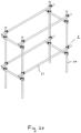
- Scaffolding is used in a wide variety of applications, including, but not limited to, multi-story building construction, bridge construction, and the erection of temporary or semi-permanent bleachers, stages, etc.
- Often scaffolding is formed from a series of pipes or tubes that are clamped together to form a rigid structure of, at times, considerable height. For obvious safety reasons, the manner in which scaffolding tubing is secured together is important.
- GB2029497 discloses a clamp according to the preamble of claim 1 and US2019160632 a clamp used for other purposes.
- a scaffolding tube clamp comprising at least one pair of body portions, each pair of body portions comprising a base and a top, each base and top having a first end hingedly connected to one another to permit the base and top to be rotatably received about the exterior surface of a scaffolding tube, a rotatable bolt engageable with a first hole positioned in a second end of the top and engageable with a second hole in a second end of the base, when the bolt is engaged with the first and second holes rotation of the bolt in a first direction connects the second ends of the top and base and moves the second ends closer to one another in a clamping arrangement about a scaffolding tube received therebetween, and rotation of the bolt in a second opposite direction releases the connection between the second ends of the top and the base permitting their rotational movement about the hinged connection, the bolt having a head and a threaded shaft, the shaft having a first threade
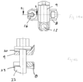
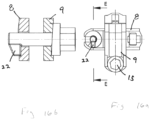
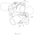
- FIG. 1 through 19b show a first embodiment.
- Figures 20 through 32c show a second embodiment.
- Figures 33 through 46 show a third embodiment, and some adaptations of that embodiment.
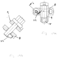
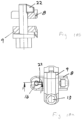
- Figures 47 through 53 show a further embodiment and adaptations as of Figure 51 that form part of the present invention.
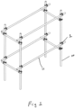
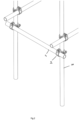
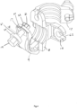
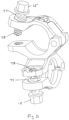
- a clamp assembly 1 may consist generally of two clamping members 2 and 3, secured together at approximately 90° and each capable of being received about the exterior surface of a scaffolding tube.
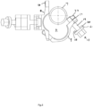
- Each clamp member includes a pair of curved body portions 4 and 5 that are hinged at first ends in order to form a generally circular cross-sectional enclosure or opening 6 within which can be received a scaffolding tube 7.
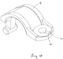
- one of the pair of body portions comprises a base 8 and the other comprises a top 9.
- Two bases may be secured together to hold two lengths of tubing at approximately 90 degrees to one another.
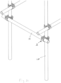
- clamp assembly 1 may be secured about a vertically oriented tube 10 and an adjacent generally horizontally oriented tube 11.
- the rotatable top 9 may include a tab 12 such that inserting the scaffolding tube into the circular enclosure applies a downwardly directed force to the tab, encouraging the curved body portion to rotate to a closed position where both curved body portions generally encompass the exterior surface of tubing 7.
- tab 12 is positioned on rotating sleeve 13 that is mounted about pin or axle 14 to permit top 9 to rotate relative to base 8.
- the exterior surface of the tube will contact tab 12, helping to encourage sleeve 13, together with top 9, to rotate about pin 14 toward a closed configuration. It will be appreciated that this interaction between tab 12 and tube 7 will help to assist in "closing" the clamp during assembly of the scaffolding and will help to simplify the process that an operator needs to complete in order to secure the tubing within the opening of the clamp.
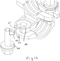
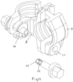
- a bolt 15 may be inserted through a first opening or hole in a second end of rotatable top 9 and a second complimentary opening or hole in a second end of base 8, and then rotated to lock the two curved portions together, thereby securely holding the scaffold tube in place.
- bolt 15 locks the two curved body portions together through interaction of one or more ramped surfaces.
- base 8 includes a ramped surface 16 and top 9 includes ramped surface 17.
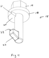
- Bolt 15 includes a ramped surface 20 on the inside portion 18 of its head 19.
- ramped surface 20 will be complimentary to ramped surface 17.
- Head 19 will be larger than the opening or hole in top 9.
- the opposite end 21 of the bolt includes an arm member 22 that extends outwardly, approximately perpendicular to the longitudinal axis of the shaft of the bolt.
- ramped surface 20 on head 19 will engage ramped surface 17 on top 9 to effectively drive top 9 away from head 19 and closer to base 8 (ie. by effectively expanding the distance between head 19 and top 9 on account of the interaction of the two ramped surfaces).
- This action further compresses the two portions of the clamp member about the exterior surface of the tube, effectively locking the clamp about the tube.
- Rotating the bolt in the opposite direction unlocks the tube from the clamp.
- the second hole or opening in base 8 is preferably equipped with a keyway opening or slot 62 to permit the passage of arm 23 therethrough such that rotation of the bolt when the arm is received through the slot 62 will cause the bolt to be retained within the hole in base 8.
- the relative position of the bolt with respect to the top and base may be reversed such that the head of the bolt bears against the base.
- the relative angle of threads on bolts that secure together scaffolding tubes must not exceed a predefined limit in order to help ensure that scaffolding clamps do not readily loosen when exposed to vibrational forces (through construction, wind application, earthquake, etc.).
- the applicant has found that through incorporating cammed or ramped surfaces as described herein, it is able to provide a solid and readily operable mechanism that draws together the outer or second ends of the curved body portions with a minimal rotation of the bolt, while still maintaining a relatively low angular degree of the connecting mechanism. That is, in the case of traditionally used threaded bolts, significant rotation of the bolt is necessary in order to tighten it to enable the two curved surfaces to be drawn together.
- Ramped surfaces 17 and 20 include vertical portions 60 and 61, respectively.
- vertical portions 60 and 61 are positioned such that when bolt 15 is rotated counterclockwise (i.e. to "undo" the latching mechanism" the two vertical portions 60 and 61 will come into contact with one another when arm 22 is aligned with slot 62 in base 8 that will permit drawing arm 22 through the slot, and hence through base 8, to allow the bolt to be fully retracted from the base and permit top 9 to rotate away from base 8 to effectively "open” the clamp.
- FIG. 19c and 19D there is shown a slightly modified version of the scaffolding tube clamp that includes an insert or adapter 65 that is releasably securable to top portion 9 in order to accommodate scaffolding tubes or pipes of different diameters. That is, where desired or necessary insert 65 can be releasably secured to top 9 in order to allow the clamp to be secured about the exterior diameter of a scaffolding tube or pipe that is slightly smaller in diameter than in instances where insert 65 is not required.
- insert 65 can be releasably secured to top 9 through any one of a wide variety of different manners or mechanical structures.
- a pair of spring tabs 66 extend through a hole 67 in top 9 such that they engage an outer surface of top 9 when received through hole 67. In that manner, insert 65 is retained within the curved body portion 4 that is formed by top 9, while being easily removed to accommodate tubes or pipes of a larger diameter.
- Figures 19c and 19D also show a slight alteration to the ramped surface 16 wherein the surface includes a stop 68 against which arm 22 will be received when bolt 15 is rotated fully toward its engaged position. Stop 68 will prevent an over tightening of the bolt which could in some instances result in a crushing or otherwise damaging force being applied to the exterior surface of the scaffolding tube or piping.
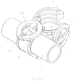
- the portion of clamp 1 that is secured about vertical tube 10 includes a slot 25 to retain rotating ring in place on base 8, whereas the portion of clamp 1 that secures horizontal tube 14 employs a fully removable rotating ring 24.
- rotation of ring 24 has the effect of drawing together the outer ends of tops 9 and basis 8 to affectively apply a compressive force about the exterior surface of the scaffolding tubing and securely hold the tubing in place.
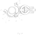
- each of base 8 and top 9 include lip portions 26 and 27, respectively. Lip portions 26 and 27 are directed away from one another, for example as shown in Figure 25 .
- Rotating ring 24 includes an internal opening 28 that has a slot 29. Slot 29 is configured to be received about one of lip portions 26 and 27 to enable ring 24 to be received over the two respective outer ends of base 8 and top 9 with lip portions 26 and 27 extending upwardly beyond the upper surface 30 of ring 24, as, for example, shown in Figure 26 .
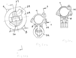
- Figures 28 through 32 show the function of ring 24 and how through rotating the ring the ends of base 8 and top 9 can be drawn together in order to compress clamp 1 about the exterior surface of tube 7 (not shown in these particular Figures).
- Opening 28 in ring 24 is largely comprised of two arcuate or cammed portions, 31 and 32, respectively.
- cammed portion 31 engages undercut portion 33 of lip 26 on base 8.
- cammed portion 32 engages undercut portion 34 of lip 27 on top 9.
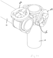
- FIG. 33 through 46 there is shown a further embodiment.
- much of the scaffolding clamp shown in this embodiment is the same or similar to that of the embodiments shown in Figures 1 through 32 .
- the primary difference between the embodiments is the manner in which top 9 is secured or fastened to base 8.
- base 8 includes a pair of arms 41 and 42 that are rotatably secured to the base by a pin or bolt 43.
- a sleeve 52 can be used to maintain the arms 41 and 42 spaced apart by a pre-determined distance
- the distal ends of arms 41 and 42 (opposite to the ends which receive pin or bolt 43) contain at least one pair of holes 46 through which a pin or bolt 44 is received in order to rotatably secure eccentric wheel or cam 40 to the ends of the pair of arms.
- arms 41 and 42 can be rotated to permit eccentric wheel or cam 40 to engage a flange 45 extending outwardly from the distal end of top 9.
- the distal ends of arms 41 and 42 may include two pairs of holes 46 that allow pin or bolt 44 to be inserted through arms 41 and 42 at two different distances from pin 43.
- the lower set of holes is designed to accommodate a scaffolding tube of a smaller diameter (for example 43 millimeters) as opposed to the outer set of holes which can be utilized to accommodate a tube of a slightly larger diameter (for example 48 millimeters).
- the interior curved surfaces of rotating tops 9 and bases 8 have a radius that is sized to be slightly larger than that of the smallest diameter tube for which the clamp is designed and also slightly smaller than that of the largest diameter tube for which the clamp is designed.
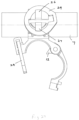
- activation of eccentric wheel or cam 40 will cause contact between top 9 and tube 7 and between base 8 and tube 7 at a single contact zone along the surface of each of rotatable top 9 and base 8, positioned generally at the central area of the curved body portions (see Figure 41 ).
- eccentric wheel or cam 40 results in two contact zones between rotatable top 9 and tube 7 and two contact zones between base 8 and tube 7 (see Figure 39 ).
- top 9 and base 8 received about the exterior surface of a scaffolding tube 7, arms 41 and 42 can be rotated to a position wherein they are approximately perpendicular to base 8 such that eccentric wheel or cam 40 is positioned above and adjacent to flange 45.
- the upper surface 47 of flange 45 may be slightly radiused to accommodate the curved eccentric surface of wheel or cam 40.
- rotation of eccentric wheel or cam 40 will cause its exterior surface to engage radiused surface 47, effectively driving flange 45 toward bolt 43 and causing rotatable top 9 and base 8 to be drawn into contact with the exterior surface of tube 7.
- eccentric wheel or cam 40 is further rotated its cammed or eccentric outer surface will enhance the clamping force applied to the exterior surface of tube 7, to thereby securely hold the scaffold tube clamp in place.
- eccentric wheel or cam 40 may include a post 48 that can be hit with a hammer or other tool causing the wheel or cam to rotate and become locked in position.
- eccentric wheel or cam 40 may include a bore 49 into which a tool or handle 50 can be inserted in order to apply leverage and to rotate the wheel or cam into its locked or unlocked configuration. In this embodiment, removal of tool 50 when eccentric wheel or cam 40 is in its locked configuration prevents unauthorized individuals from easily or readily unlocking the scaffolding tube clamp without access to an authorized tool.
- the interior configuration of bore 49 and the exterior surface of tool 50 could be of a geometric shape (for example, star, non-uniform hexagon, etc) that prevents objects other than tool 50 from being inserted into bore 49, to further limit unauthorized rotation of eccentric wheel or cam 40.
- top 9 and base 8 that contact scaffolding tube 7 may include a series of ribs or ridges 51 that help to concentrate the clamping load along specific lines and to thereby help to prevent slippage or sliding of the clamp along the surface of the tube.
- the scaffolding tube clamp of the embodiment shown in Figures 33 through 46 presents the ability to apply a significant clamping force against the exterior surface of a scaffolding tube through rotation of eccentric wheel or cam 40.
- the utilization of a pair of arms 41 and 42, having multiple holes 46 in their ends, permits an adjustment of the clamp to allow it to engage scaffolding tubes of different diameters.
- the operation of eccentric wheel or cam 40 applies a force against flange 45 that draws rotatable top 9 toward base 8 to securely hold a scaffolding tube there between. Through applying the force against flange 45, additional torque can effectively be applied to rotatable top 9 on account of the moment arm created by the flange. Engagement and disengagement of the eccentric wheel or cam lock is accomplished both quickly and easily. For added safety a dedicated tool can be required to prevent authorized loosening or disengagement of the eccentric wheel or cam lock.
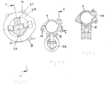
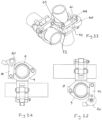
- FIG. 47 through 53 there is shown an embodiment of the scaffolding tube clamp wherein bolt 15 incorporates a threaded portion.
- the overall structure of the scaffolding tube clamp is generally similar to that shown in Figures 1 through 19D .
- the primary difference in the embodiment of Figures 47 through 53 is that bolt 15 contains a threaded portion 70.
- bolt 15 once again has a ramped surface 20 that engages a ramped surface 17 on top 9 as the bolt is rotated, in order to drive the outer end of top 9 toward outer end of base 8 and to compress the two portions of the clamp member together about the exterior surface of the scaffolding tube or pipe. That is, the interaction between bolt 15 and top 9 (and more particularly ramped surfaces 17 and 20) is essentially the same as in the embodiment shown in Figures 1 through 19D .
- threaded portion 70 mates with a hole 71 in base 4 where hole 71 has a thread corresponding to that of threaded portion 70.
- Threaded portion 70 is of a constant pitch along its length. In this instance the pitch of threaded portion 70 is relatively coarse such that one full rotation of the bolt causes top 9 to be drawn toward base 8 to a significant degree, taking into account the particular application and circumstances at hand. In one embodiment, one full rotation of bolt 15 moves top 9 closer to base 8 by approximately 8 mm. It will be appreciated that other pitches and rates of advance of the bolt with one revolution can be used.
- the scaffolding tube clamp of Figures 47 through 49 is first "opened” to permit a scaffolding tube to be received within the clamping members. Top 9 is then rotated and received about the exterior surface of the scaffolding tube, after which threaded portion 70 of bolt 15 can be received within hole 71 for threaded engagement therewith. At that point, rotation of bolt 15 will cause the course threads of portion 70 and hole 71 to draw top 9 toward base 8 in a relatively fast manner to enable the clamp to be quickly secured about the surface of the scaffolding tube with only minimal rotation of bolt 15.
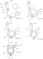
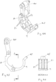
- Figures 51 through 53 show a slight variation to the embodiment of Figures 47 through 50 , corresponding to the present invention, wherein bolt 15 has a first or upper threaded portion 75 and second or lower threaded portion 76.
- upper threaded portion 75 has a larger diameter thread 77 than the thread 78 on lower threaded portion 76.
- top 9 With a bolt 15 of this construction, top 9 will be fitted with a hole having a thread corresponding to larger diameter thread 77 and bottom 8 will have a hole corresponding to smaller diameter thread 78.
- rotation of bolt 15 will then result in thread 77 engaging the correspondingly threaded hole in top 9 and thread 78 engaging the correspondingly threaded hole in base 8.
- Larger diameter thread 77 and smaller diameter thread 78 will have different pitches.
- large diameter thread 77 has a coarse thread whereas small diameter thread 78 has a finer thread.
- Rotation of bolt 15 will thus result in the courser 77 causing top 9 to be drawn toward base 8 with minimal bolt rotation to allow the clamp to be secured about the scaffolding tube in an expeditious manner.
- the finer thread 78 provides for enhanced strength and also will tend to provide better vibration resistance than the course thread portion. It will be appreciated that the relative positions of the large and small diameter threaded sections of bolt 15 could be reversed, as could the relative positions of the coarse and fine threads.
Landscapes
- Engineering & Computer Science (AREA)
- General Engineering & Computer Science (AREA)
- Architecture (AREA)
- Mechanical Engineering (AREA)
- Civil Engineering (AREA)
- Structural Engineering (AREA)
- Mutual Connection Of Rods And Tubes (AREA)
- Clamps And Clips (AREA)
Claims (2)
- Pince de tube d'échafaudage (1) comprenant :une paire de parties de corps fixées ensemble à 90 degrés l'une par rapport à l'autre, chaque paire de parties de corps comprenant une base (8) et un dessus (9), chaque base (8) et chaque dessus (9) présentant une première extrémité reliée de manière articulée l'une à l'autre pour permettre à la base (8) et au dessus (9) d'être reçus en rotation autour d'une surface extérieure d'un tube d'échafaudage (7),un boulon rotatif (15) pouvant venir en prise avec un premier trou positionné dans une seconde extrémité du dessus (9) et pouvant venir en prise avec un second trou dans une seconde extrémité de la base (8), lorsque le boulon (15) est mis en prise avec les premier et second trous, une rotation du boulon (15) dans une première direction relie les secondes extrémités du dessus (9) et de la base (8) et rapproche les secondes extrémités l'une de l'autre dans un agencement de serrage autour d'un tube d'échafaudage (7) pouvant être reçu entre celles-ci, et une rotation du boulon (15) dans une seconde direction opposée libère la liaison entre les secondes extrémités du dessus (9) et la base (8), permettant leur mouvement de rotation autour de la liaison articulée,le boulon (15) présentant une tête et une tige, la tige présentant une première partie filetée avec un premier filetage situé adjacent à la tête, la tige présentant une seconde partie filetée avec un second filetage au niveau d'une extrémité inférieure du boulon (15), la pince d'échafaudage (1) étant caractérisée parla première partie filetée présentant un diamètre plus grand que celui de la seconde partie filetée, la première partie filetée présentant un filetage plus grossier que celui de la seconde partie filetée, le premier trou présentant des filetages complémentaires au premier filetage et le second trou présentant des filetages complémentaires au second filetage, les premier et second filetage présentant des pas différents,et dans laquelle le dessus (9) inclut une languette (12) sur une surface intérieure adjacente à sa liaison articulée à la base (8), la languette (12) pouvant être mise en prise avec un tube d'échafaudage (7) reçu entre le dessus (9) et la base (8), dans laquelle une insertion du tube d'échafaudage (7) entre le dessus et la base provoque une mise en prise de la languette (12) avec le tube d'échafaudage (7) et amène la seconde extrémité du dessus (9) à être tournée vers la seconde extrémité de la base (8).
- Pince de tube d'échafaudage (1) selon la revendication 1, dans laquelle une rotation du boulon (15) sur une révolution de 360 degrés amène le boulon (15) à se déplacer soit vers l'intérieur, soit vers l'extérieur par le second trou sur au moins 8 mm.
Applications Claiming Priority (3)
| Application Number | Priority Date | Filing Date | Title |
|---|---|---|---|
| US201962869812P | 2019-07-02 | 2019-07-02 | |
| US201962941093P | 2019-11-27 | 2019-11-27 | |
| PCT/CA2020/050911 WO2021000042A1 (fr) | 2019-07-02 | 2020-06-30 | Pince de tube d'échafaudage |
Publications (4)
| Publication Number | Publication Date |
|---|---|
| EP3994321A1 EP3994321A1 (fr) | 2022-05-11 |
| EP3994321A4 EP3994321A4 (fr) | 2023-07-26 |
| EP3994321B1 true EP3994321B1 (fr) | 2024-08-07 |
| EP3994321C0 EP3994321C0 (fr) | 2024-08-07 |
Family
ID=74100421
Family Applications (1)
| Application Number | Title | Priority Date | Filing Date |
|---|---|---|---|
| EP20834684.1A Active EP3994321B1 (fr) | 2019-07-02 | 2020-06-30 | Pince de tube d'échafaudage |
Country Status (5)
| Country | Link |
|---|---|
| US (1) | US11959292B2 (fr) |
| EP (1) | EP3994321B1 (fr) |
| CN (1) | CN114341448A (fr) |
| CA (1) | CA3143771A1 (fr) |
| WO (1) | WO2021000042A1 (fr) |
Families Citing this family (5)
| Publication number | Priority date | Publication date | Assignee | Title |
|---|---|---|---|---|
| USD1017832S1 (en) * | 2020-07-17 | 2024-03-12 | Global Engineers Investment Singapore Pte. Ltd. | Tower |
| GB2599459B (en) * | 2021-01-25 | 2022-10-26 | Rjm Fittings Ltd | A coupling device for scaffolding |
| US12227244B2 (en) * | 2021-03-25 | 2025-02-18 | Safesmart Llc | Safety rail |
| USD992407S1 (en) * | 2022-06-01 | 2023-07-18 | Concealfab, Inc. | Dual pipe clamp |
| CN117803163B (zh) * | 2023-04-11 | 2025-12-26 | 苏州博华建筑装饰工程有限公司 | 便于组装拆卸的钢结构工程防护支架 |
Citations (1)
| Publication number | Priority date | Publication date | Assignee | Title |
|---|---|---|---|---|
| GB2029497A (en) * | 1978-08-17 | 1980-03-19 | Sgb Group Ltd | Improvements in or relating to a scaffolding coupler |
Family Cites Families (31)
| Publication number | Priority date | Publication date | Assignee | Title |
|---|---|---|---|---|
| US1539826A (en) * | 1923-11-14 | 1925-06-02 | American Optical Corp | End-piece-clamping means |
| GB404800A (en) * | 1932-12-13 | 1934-01-25 | George William Amor | A coupling device for use in the erection of scaffolding and like temporary structures |
| US2165221A (en) * | 1936-07-03 | 1939-07-11 | Burton John | Scaffolding clamp |
| GB547014A (en) * | 1941-03-13 | 1942-08-10 | Arnold Clarence Marshall | An improved clamp for scaffold poles or other hollow or solid elongated bodies |
| GB853184A (en) * | 1955-11-17 | 1960-11-02 | David Roberts & Co Engineers L | Improvements in or relating to scaffolding |
| US3167346A (en) * | 1963-04-24 | 1965-01-26 | Marvin O Miller | Quick acting hook |
| US3876318A (en) * | 1973-07-16 | 1975-04-08 | Standard Pressed Steel Co | Shaft gripping collar |
| FR2337238A1 (fr) * | 1975-12-31 | 1977-07-29 | Meynieu Francis | Perfectionnements aux elements de montage des echafaudages tubulaires |
| JPS6116479Y2 (fr) * | 1980-07-11 | 1986-05-21 | ||
| ZA82588B (en) * | 1981-02-06 | 1982-12-29 | George W Jackson | Components for a support structure for pouring concrete |
| US4728202A (en) * | 1987-01-14 | 1988-03-01 | Emerson Electric Co. | Shaft locking collar for bearing assemblies |
| GB2214554B (en) * | 1988-01-15 | 1991-08-07 | Richard Maurice Morgan | Scaffold fitting |
| IT215069Z2 (it) * | 1988-10-10 | 1990-07-30 | 3T S P A | Attacco per manubrio di bicicletta |
| CN2057485U (zh) * | 1989-09-07 | 1990-05-23 | 林建真 | 可靠防脱转螺杆螺母 |
| JPH0796833B2 (ja) * | 1992-09-25 | 1995-10-18 | 政太郎 佐藤 | 管材連結用クランプ金具組立体 |
| US5536127A (en) * | 1994-10-13 | 1996-07-16 | Pennig; Dietmar | Headed screw construction for use in fixing the position of an intramedullary nail |
| US5997012A (en) * | 1996-06-27 | 1999-12-07 | Brian; Frank J. | Differential thread control of chuck gripping of work |
| US6125526A (en) * | 1999-05-12 | 2000-10-03 | Robert Bosch Corporation | Method of fastening a first member to a second member |
| CA2334126A1 (fr) * | 2001-02-02 | 2002-08-02 | Aluma Enterprises Inc. | Dispositif de fixation pour echafaudage |
| US6786302B2 (en) * | 2002-02-20 | 2004-09-07 | National University Of Singapore | Triple coupler for flexible scaffold system |
| US6789647B1 (en) * | 2003-05-27 | 2004-09-14 | Chi-Hsang Yeh | Escape mechanism for high-rise |
| US7665699B2 (en) * | 2004-06-18 | 2010-02-23 | Innovative Office Products, Inc. | Electronic device mounting bracket for a horizontal support |
| JP5090016B2 (ja) * | 2006-04-26 | 2012-12-05 | ホリーコーリア株式会社 | クランプ |
| WO2008107498A1 (fr) * | 2007-03-08 | 2008-09-12 | Rotor Componentes Tecnológicos, S.L | Potence de guidon pour bicyclettes à système de fixation comprenant des brides filetées à pas de vis différents |
| JP5514644B2 (ja) * | 2010-06-22 | 2014-06-04 | 本田技研工業株式会社 | 作業機のハンドル装置 |
| GB201204015D0 (en) * | 2012-03-07 | 2012-04-18 | Syncromesh Systems Ltd | Improvements in and relating to couplers |
| CN203891453U (zh) * | 2014-05-22 | 2014-10-22 | 河海大学 | 带梅花头螺栓的钢管脚手架扣件 |
| US20180187704A1 (en) * | 2016-09-14 | 2018-07-05 | Michael Chau-Lun CHANG | Hands-free dual clamp device |
| GB2557982B (en) * | 2016-12-21 | 2021-09-22 | Jjb Products Ltd | Apparatus for retaining scaffolding tubes |
| US10500699B2 (en) * | 2017-11-30 | 2019-12-10 | Michael Chau-Lun CHANG | Hands-free dual clamp device |
| CN108326778A (zh) * | 2018-03-12 | 2018-07-27 | 成都德立诚机械设备有限公司 | 一种可变径自动夹具 |
-
2020
- 2020-06-30 EP EP20834684.1A patent/EP3994321B1/fr active Active
- 2020-06-30 CN CN202080062044.0A patent/CN114341448A/zh active Pending
- 2020-06-30 WO PCT/CA2020/050911 patent/WO2021000042A1/fr not_active Ceased
- 2020-06-30 US US17/621,294 patent/US11959292B2/en active Active
- 2020-06-30 CA CA3143771A patent/CA3143771A1/fr active Pending
Patent Citations (1)
| Publication number | Priority date | Publication date | Assignee | Title |
|---|---|---|---|---|
| GB2029497A (en) * | 1978-08-17 | 1980-03-19 | Sgb Group Ltd | Improvements in or relating to a scaffolding coupler |
Also Published As
| Publication number | Publication date |
|---|---|
| EP3994321A4 (fr) | 2023-07-26 |
| WO2021000042A1 (fr) | 2021-01-07 |
| CN114341448A (zh) | 2022-04-12 |
| EP3994321C0 (fr) | 2024-08-07 |
| US11959292B2 (en) | 2024-04-16 |
| CA3143771A1 (fr) | 2021-01-07 |
| EP3994321A1 (fr) | 2022-05-11 |
| US20220349191A1 (en) | 2022-11-03 |
Similar Documents
| Publication | Publication Date | Title |
|---|---|---|
| US11959292B2 (en) | Scaffolding tube clamp | |
| US8347665B2 (en) | Self-balancing locking mechanism for doors | |
| US6652012B1 (en) | Hoist ring | |
| US6619161B1 (en) | Anti-tamper nut | |
| US10215208B2 (en) | Fastener for securing together two panels | |
| US8662794B2 (en) | Helical pile adapter | |
| WO2017143040A1 (fr) | Élément de fixation de haute sécurité à élément de retenue d'enveloppe voilé | |
| CN101573541A (zh) | 连接销及其使用方法 | |
| AU2022202155A1 (en) | Subsea clamp connector and subsea clamp connector arrangement comprising such a clamp connector | |
| EP2935782A1 (fr) | Ensemble cloche de repêchage ainsi que systèmes et procédés d'utilisation de ce dernier | |
| US8991226B2 (en) | Storm grate lock device and method of use | |
| CN1498316A (zh) | 联轴器 | |
| CN114233739A (zh) | 一种用于连接和紧固零件的截断式防止螺母回旋松动装置 | |
| AU2020227071A1 (en) | A Lock Mechanism for a Scaffolding Clamp | |
| TWI275712B (en) | A tightening system for secure connection of at least two elements with one another | |
| WO2008004039A2 (fr) | Mecanisme de boulon a limitation de couple | |
| JP4156976B2 (ja) | タイヤ成型ドラムの連結装置 | |
| US10612539B2 (en) | Rod clamp assembly and method | |
| CN117780761A (zh) | 连接装置 | |
| EP4402388B1 (fr) | Élément de fixation de sécurité élevée avec clé de couplage d'entraînement | |
| WO2009039583A1 (fr) | Ensemble de pied supérieur pour une entretoise de construction | |
| DE10060963B4 (de) | Verdrehsicherung | |
| KR102299083B1 (ko) | 프레타이용 안전연결구 | |
| EP1300217B1 (fr) | Support de perçeuse avec plaque de sol fixable | |
| CN112207748B (zh) | 一种高强螺栓紧固用扳手 |
Legal Events
| Date | Code | Title | Description |
|---|---|---|---|
| STAA | Information on the status of an ep patent application or granted ep patent |
Free format text: STATUS: THE INTERNATIONAL PUBLICATION HAS BEEN MADE |
|
| PUAI | Public reference made under article 153(3) epc to a published international application that has entered the european phase |
Free format text: ORIGINAL CODE: 0009012 |
|
| STAA | Information on the status of an ep patent application or granted ep patent |
Free format text: STATUS: REQUEST FOR EXAMINATION WAS MADE |
|
| 17P | Request for examination filed |
Effective date: 20220202 |
|
| AK | Designated contracting states |
Kind code of ref document: A1 Designated state(s): AL AT BE BG CH CY CZ DE DK EE ES FI FR GB GR HR HU IE IS IT LI LT LU LV MC MK MT NL NO PL PT RO RS SE SI SK SM TR |
|
| DAV | Request for validation of the european patent (deleted) | ||
| DAX | Request for extension of the european patent (deleted) | ||
| A4 | Supplementary search report drawn up and despatched |
Effective date: 20230627 |
|
| RIC1 | Information provided on ipc code assigned before grant |
Ipc: F16B 21/02 20060101ALI20230621BHEP Ipc: F16B 2/14 20060101ALI20230621BHEP Ipc: F16B 5/02 20060101ALI20230621BHEP Ipc: E04G 7/14 20060101ALI20230621BHEP Ipc: F16B 7/04 20060101ALI20230621BHEP Ipc: E04G 7/16 20060101AFI20230621BHEP |
|
| GRAP | Despatch of communication of intention to grant a patent |
Free format text: ORIGINAL CODE: EPIDOSNIGR1 |
|
| STAA | Information on the status of an ep patent application or granted ep patent |
Free format text: STATUS: GRANT OF PATENT IS INTENDED |
|
| RIC1 | Information provided on ipc code assigned before grant |
Ipc: F16B 21/02 20060101ALI20240313BHEP Ipc: F16B 2/14 20060101ALI20240313BHEP Ipc: F16B 5/02 20060101ALI20240313BHEP Ipc: E04G 7/14 20060101ALI20240313BHEP Ipc: F16B 7/04 20060101ALI20240313BHEP Ipc: E04G 7/16 20060101AFI20240313BHEP |
|
| INTG | Intention to grant announced |
Effective date: 20240404 |
|
| GRAS | Grant fee paid |
Free format text: ORIGINAL CODE: EPIDOSNIGR3 |
|
| GRAA | (expected) grant |
Free format text: ORIGINAL CODE: 0009210 |
|
| STAA | Information on the status of an ep patent application or granted ep patent |
Free format text: STATUS: THE PATENT HAS BEEN GRANTED |
|
| AK | Designated contracting states |
Kind code of ref document: B1 Designated state(s): AL AT BE BG CH CY CZ DE DK EE ES FI FR GB GR HR HU IE IS IT LI LT LU LV MC MK MT NL NO PL PT RO RS SE SI SK SM TR |
|
| REG | Reference to a national code |
Ref country code: GB Ref legal event code: FG4D |
|
| REG | Reference to a national code |
Ref country code: CH Ref legal event code: EP |
|
| REG | Reference to a national code |
Ref country code: IE Ref legal event code: FG4D |
|
| REG | Reference to a national code |
Ref country code: DE Ref legal event code: R096 Ref document number: 602020035492 Country of ref document: DE |
|
| U01 | Request for unitary effect filed |
Effective date: 20240807 |
|
| U07 | Unitary effect registered |
Designated state(s): AT BE BG DE DK EE FI FR IT LT LU LV MT NL PT RO SE SI Effective date: 20240902 |
|
| PG25 | Lapsed in a contracting state [announced via postgrant information from national office to epo] |
Ref country code: NO Free format text: LAPSE BECAUSE OF FAILURE TO SUBMIT A TRANSLATION OF THE DESCRIPTION OR TO PAY THE FEE WITHIN THE PRESCRIBED TIME-LIMIT Effective date: 20241107 |
|
| PG25 | Lapsed in a contracting state [announced via postgrant information from national office to epo] |
Ref country code: GR Free format text: LAPSE BECAUSE OF FAILURE TO SUBMIT A TRANSLATION OF THE DESCRIPTION OR TO PAY THE FEE WITHIN THE PRESCRIBED TIME-LIMIT Effective date: 20241108 Ref country code: PL Free format text: LAPSE BECAUSE OF FAILURE TO SUBMIT A TRANSLATION OF THE DESCRIPTION OR TO PAY THE FEE WITHIN THE PRESCRIBED TIME-LIMIT Effective date: 20240807 |
|
| PG25 | Lapsed in a contracting state [announced via postgrant information from national office to epo] |
Ref country code: IS Free format text: LAPSE BECAUSE OF FAILURE TO SUBMIT A TRANSLATION OF THE DESCRIPTION OR TO PAY THE FEE WITHIN THE PRESCRIBED TIME-LIMIT Effective date: 20241207 |
|
| PG25 | Lapsed in a contracting state [announced via postgrant information from national office to epo] |
Ref country code: HR Free format text: LAPSE BECAUSE OF FAILURE TO SUBMIT A TRANSLATION OF THE DESCRIPTION OR TO PAY THE FEE WITHIN THE PRESCRIBED TIME-LIMIT Effective date: 20240807 |
|
| PG25 | Lapsed in a contracting state [announced via postgrant information from national office to epo] |
Ref country code: ES Free format text: LAPSE BECAUSE OF FAILURE TO SUBMIT A TRANSLATION OF THE DESCRIPTION OR TO PAY THE FEE WITHIN THE PRESCRIBED TIME-LIMIT Effective date: 20240807 Ref country code: RS Free format text: LAPSE BECAUSE OF FAILURE TO SUBMIT A TRANSLATION OF THE DESCRIPTION OR TO PAY THE FEE WITHIN THE PRESCRIBED TIME-LIMIT Effective date: 20241107 |
|
| PG25 | Lapsed in a contracting state [announced via postgrant information from national office to epo] |
Ref country code: RS Free format text: LAPSE BECAUSE OF FAILURE TO SUBMIT A TRANSLATION OF THE DESCRIPTION OR TO PAY THE FEE WITHIN THE PRESCRIBED TIME-LIMIT Effective date: 20241107 Ref country code: PL Free format text: LAPSE BECAUSE OF FAILURE TO SUBMIT A TRANSLATION OF THE DESCRIPTION OR TO PAY THE FEE WITHIN THE PRESCRIBED TIME-LIMIT Effective date: 20240807 Ref country code: NO Free format text: LAPSE BECAUSE OF FAILURE TO SUBMIT A TRANSLATION OF THE DESCRIPTION OR TO PAY THE FEE WITHIN THE PRESCRIBED TIME-LIMIT Effective date: 20241107 Ref country code: IS Free format text: LAPSE BECAUSE OF FAILURE TO SUBMIT A TRANSLATION OF THE DESCRIPTION OR TO PAY THE FEE WITHIN THE PRESCRIBED TIME-LIMIT Effective date: 20241207 Ref country code: HR Free format text: LAPSE BECAUSE OF FAILURE TO SUBMIT A TRANSLATION OF THE DESCRIPTION OR TO PAY THE FEE WITHIN THE PRESCRIBED TIME-LIMIT Effective date: 20240807 Ref country code: GR Free format text: LAPSE BECAUSE OF FAILURE TO SUBMIT A TRANSLATION OF THE DESCRIPTION OR TO PAY THE FEE WITHIN THE PRESCRIBED TIME-LIMIT Effective date: 20241108 Ref country code: ES Free format text: LAPSE BECAUSE OF FAILURE TO SUBMIT A TRANSLATION OF THE DESCRIPTION OR TO PAY THE FEE WITHIN THE PRESCRIBED TIME-LIMIT Effective date: 20240807 |
|
| PG25 | Lapsed in a contracting state [announced via postgrant information from national office to epo] |
Ref country code: SM Free format text: LAPSE BECAUSE OF FAILURE TO SUBMIT A TRANSLATION OF THE DESCRIPTION OR TO PAY THE FEE WITHIN THE PRESCRIBED TIME-LIMIT Effective date: 20240807 |
|
| PG25 | Lapsed in a contracting state [announced via postgrant information from national office to epo] |
Ref country code: CZ Free format text: LAPSE BECAUSE OF FAILURE TO SUBMIT A TRANSLATION OF THE DESCRIPTION OR TO PAY THE FEE WITHIN THE PRESCRIBED TIME-LIMIT Effective date: 20240807 |
|
| PG25 | Lapsed in a contracting state [announced via postgrant information from national office to epo] |
Ref country code: SK Free format text: LAPSE BECAUSE OF FAILURE TO SUBMIT A TRANSLATION OF THE DESCRIPTION OR TO PAY THE FEE WITHIN THE PRESCRIBED TIME-LIMIT Effective date: 20240807 |
|
| PLBE | No opposition filed within time limit |
Free format text: ORIGINAL CODE: 0009261 |
|
| STAA | Information on the status of an ep patent application or granted ep patent |
Free format text: STATUS: NO OPPOSITION FILED WITHIN TIME LIMIT |
|
| PGFP | Annual fee paid to national office [announced via postgrant information from national office to epo] |
Ref country code: GB Payment date: 20250630 Year of fee payment: 6 |
|
| 26N | No opposition filed |
Effective date: 20250508 |
|
| U20 | Renewal fee for the european patent with unitary effect paid |
Year of fee payment: 6 Effective date: 20250630 |
|
| REG | Reference to a national code |
Ref country code: CH Ref legal event code: H13 Free format text: ST27 STATUS EVENT CODE: U-0-0-H10-H13 (AS PROVIDED BY THE NATIONAL OFFICE) Effective date: 20260127 |
|
| PG25 | Lapsed in a contracting state [announced via postgrant information from national office to epo] |
Ref country code: MC Free format text: LAPSE BECAUSE OF FAILURE TO SUBMIT A TRANSLATION OF THE DESCRIPTION OR TO PAY THE FEE WITHIN THE PRESCRIBED TIME-LIMIT Effective date: 20240807 |
|
| PG25 | Lapsed in a contracting state [announced via postgrant information from national office to epo] |
Ref country code: IE Free format text: LAPSE BECAUSE OF NON-PAYMENT OF DUE FEES Effective date: 20250630 |
|
| PG25 | Lapsed in a contracting state [announced via postgrant information from national office to epo] |
Ref country code: CH Free format text: LAPSE BECAUSE OF NON-PAYMENT OF DUE FEES Effective date: 20250630 |