EP3996300A1 - Verfahren zum senden und empfangen von dateneinheiten sowie vorrichtungen - Google Patents
Verfahren zum senden und empfangen von dateneinheiten sowie vorrichtungen Download PDFInfo
- Publication number
- EP3996300A1 EP3996300A1 EP20844140.2A EP20844140A EP3996300A1 EP 3996300 A1 EP3996300 A1 EP 3996300A1 EP 20844140 A EP20844140 A EP 20844140A EP 3996300 A1 EP3996300 A1 EP 3996300A1
- Authority
- EP
- European Patent Office
- Prior art keywords
- mpdu
- field
- value
- retransmitted
- subframe
- Prior art date
- Legal status (The legal status is an assumption and is not a legal conclusion. Google has not performed a legal analysis and makes no representation as to the accuracy of the status listed.)
- Pending
Links
Images





Classifications
-
- H—ELECTRICITY
- H04—ELECTRIC COMMUNICATION TECHNIQUE
- H04W—WIRELESS COMMUNICATION NETWORKS
- H04W28/00—Network traffic management; Network resource management
- H04W28/02—Traffic management, e.g. flow control or congestion control
- H04W28/04—Error control
-
- H—ELECTRICITY
- H04—ELECTRIC COMMUNICATION TECHNIQUE
- H04L—TRANSMISSION OF DIGITAL INFORMATION, e.g. TELEGRAPHIC COMMUNICATION
- H04L1/00—Arrangements for detecting or preventing errors in the information received
- H04L1/08—Arrangements for detecting or preventing errors in the information received by repeating transmission, e.g. Verdan system
-
- H—ELECTRICITY
- H04—ELECTRIC COMMUNICATION TECHNIQUE
- H04L—TRANSMISSION OF DIGITAL INFORMATION, e.g. TELEGRAPHIC COMMUNICATION
- H04L1/00—Arrangements for detecting or preventing errors in the information received
- H04L1/12—Arrangements for detecting or preventing errors in the information received by using return channel
- H04L1/16—Arrangements for detecting or preventing errors in the information received by using return channel in which the return channel carries supervisory signals, e.g. repetition request signals
- H04L1/18—Automatic repetition systems, e.g. Van Duuren systems
- H04L1/1867—Arrangements specially adapted for the transmitter end
- H04L1/1896—ARQ related signaling
-
- H—ELECTRICITY
- H04—ELECTRIC COMMUNICATION TECHNIQUE
- H04L—TRANSMISSION OF DIGITAL INFORMATION, e.g. TELEGRAPHIC COMMUNICATION
- H04L1/00—Arrangements for detecting or preventing errors in the information received
- H04L1/12—Arrangements for detecting or preventing errors in the information received by using return channel
- H04L1/16—Arrangements for detecting or preventing errors in the information received by using return channel in which the return channel carries supervisory signals, e.g. repetition request signals
- H04L1/18—Automatic repetition systems, e.g. Van Duuren systems
- H04L1/1812—Hybrid protocols; Hybrid automatic repeat request [HARQ]
-
- H—ELECTRICITY
- H04—ELECTRIC COMMUNICATION TECHNIQUE
- H04L—TRANSMISSION OF DIGITAL INFORMATION, e.g. TELEGRAPHIC COMMUNICATION
- H04L1/00—Arrangements for detecting or preventing errors in the information received
- H04L1/12—Arrangements for detecting or preventing errors in the information received by using return channel
- H04L1/16—Arrangements for detecting or preventing errors in the information received by using return channel in which the return channel carries supervisory signals, e.g. repetition request signals
- H04L1/18—Automatic repetition systems, e.g. Van Duuren systems
- H04L1/1829—Arrangements specially adapted for the receiver end
-
- H—ELECTRICITY
- H04—ELECTRIC COMMUNICATION TECHNIQUE
- H04L—TRANSMISSION OF DIGITAL INFORMATION, e.g. TELEGRAPHIC COMMUNICATION
- H04L1/00—Arrangements for detecting or preventing errors in the information received
- H04L1/12—Arrangements for detecting or preventing errors in the information received by using return channel
- H04L1/16—Arrangements for detecting or preventing errors in the information received by using return channel in which the return channel carries supervisory signals, e.g. repetition request signals
- H04L1/18—Automatic repetition systems, e.g. Van Duuren systems
- H04L1/1867—Arrangements specially adapted for the transmitter end
-
- H—ELECTRICITY
- H04—ELECTRIC COMMUNICATION TECHNIQUE
- H04L—TRANSMISSION OF DIGITAL INFORMATION, e.g. TELEGRAPHIC COMMUNICATION
- H04L1/00—Arrangements for detecting or preventing errors in the information received
- H04L1/12—Arrangements for detecting or preventing errors in the information received by using return channel
- H04L1/16—Arrangements for detecting or preventing errors in the information received by using return channel in which the return channel carries supervisory signals, e.g. repetition request signals
- H04L1/1607—Details of the supervisory signal
- H04L1/1614—Details of the supervisory signal using bitmaps
-
- H—ELECTRICITY
- H04—ELECTRIC COMMUNICATION TECHNIQUE
- H04L—TRANSMISSION OF DIGITAL INFORMATION, e.g. TELEGRAPHIC COMMUNICATION
- H04L1/00—Arrangements for detecting or preventing errors in the information received
- H04L1/12—Arrangements for detecting or preventing errors in the information received by using return channel
- H04L1/16—Arrangements for detecting or preventing errors in the information received by using return channel in which the return channel carries supervisory signals, e.g. repetition request signals
- H04L1/18—Automatic repetition systems, e.g. Van Duuren systems
- H04L1/1829—Arrangements specially adapted for the receiver end
- H04L1/1835—Buffer management
- H04L1/1845—Combining techniques, e.g. code combining
-
- H—ELECTRICITY
- H04—ELECTRIC COMMUNICATION TECHNIQUE
- H04W—WIRELESS COMMUNICATION NETWORKS
- H04W84/00—Network topologies
- H04W84/02—Hierarchically pre-organised networks, e.g. paging networks, cellular networks, WLAN [Wireless Local Area Network] or WLL [Wireless Local Loop]
- H04W84/10—Small scale networks; Flat hierarchical networks
- H04W84/12—WLAN [Wireless Local Area Networks]
Definitions
- This application relates to the field of communication technologies, and in particular, to a data unit sending method, a data unit receiving method, and an apparatus.
- Error control is usually performed by using methods such as a forward error correction (Forward Error Correction, FEC) encoding technology and an automatic repeat request (Automatic Repeat Request, ARQ).
- FEC Forward Error Correction
- ARQ Automatic Repeat Request
- Hybrid ARQ Hybrid ARQ
- HARQ hybrid automatic repeat request
- standards such as LTE (Long Term Evolution, Long Term Evolution).
- a receive end prestores previously received data; and when receiving retransmitted data, the receive end combines the previously received data and the received retransmitted data, to increase a success rate of decoding.
- the HARQ mechanism is usually used in a deep fading area or an edge area in a wireless network; and the mechanism usually enables a transmit end to use a high modulation and coding scheme (Modulation and Coding Scheme, MCS), to improve transmission efficiency.
- MCS Modulation and Coding Scheme
- the HARQ requires buffer to store data that needs to be combined. Therefore, the HARQ mechanism is not introduced in previous standards such as 802.11a/g/n/ac/ax.
- 802.11a/g/n/ac/ax In a future WLAN system, for example, the next-generation WLAN system in which the 802.11be standard is applied, due to improvement of hardware performance, the HARQ technology that can improve transmission reliability and efficiency is likely to be selected as one of technologies of a next-generation Wi-Fi standard. Therefore, how to design a HARQ mechanism applicable to a WLAN system is very important.
- Embodiments of this application provide a data unit method and apparatus, which are applicable to a WLAN system, and can implement HARQ transmission in the WLAN system, thereby improving transmission reliability and efficiency.
- the technical solutions are as follows:
- a data unit sending method applied to a transmit end including: sending a first aggregated media access control protocol data unit A-MPDU; determining an MPDU that needs to be retransmitted in the first A-MPDU, where the MPDU that needs to be retransmitted is included in a first A-MPDU subframe in the first A-MPDU, the first A-MPDU subframe includes a first MPDU delimiter, and the first MPDU delimiter includes a first EOF field and a first MPDU length field; and sending a second A-MPDU, where the second A-MPDU includes a second A-MPDU subframe, the second A-MPDU subframe includes the MPDU that needs to be retransmitted and a second MPDU delimiter, and the second MPDU delimiter includes a second EOF field and a second MPDU length field.
- a value of the second EOF field is the same as a value of the first EOF field, and a value of the second MPDU length field
- a data unit receiving method applied to a receive end including: receiving a first aggregated media access control protocol data unit A-MPDU; receiving a second A-MPDU, where the second A-MPDU includes a second A-MPDU subframe, the second A-MPDU subframe includes an MPDU that needs to be retransmitted in the first A-MPDU, the MPDU that needs to be retransmitted is included in a first A-MPDU subframe of the first A-MPDU, the first A-MPDU subframe includes a first MPDU delimiter, the first MPDU delimiter includes a first EOF field and a first MPDU length field, the second A-MPDU subframe includes a second MPDU delimiter, and the second MPDU delimiter includes a second EOF field and a second MPDU length field, where a value of the second EOF field is the same as a value of the first EOF field, and a value of the second MPDU length field is the same as a
- a sending apparatus including: a sending module, configured to send a first aggregated media access control protocol data unit A-MPDU; and a processing module, configured to determine an MPDU that needs to be retransmitted in the first A-MPDU, where the MPDU that needs to be retransmitted is included in a first A-MPDU subframe in the first A-MPDU, the first A-MPDU subframe includes a first MPDU delimiter, and the first MPDU delimiter includes a first EOF field and a first MPDU length field.
- the sending module is further configured to send a second A-MPDU, where the second A-MPDU includes a second A-MPDU subframe, the second A-MPDU subframe includes the MPDU that needs to be retransmitted and a second MPDU delimiter, and the second MPDU delimiter includes a second EOF field and a second MPDU length field.
- a value of the second EOF field is the same as a value of the first EOF field
- a value of the second MPDU length field is the same as a value of the second MPDU length field.
- a receiving apparatus including: a receiving module, configured to receive a first aggregated media access control protocol data unit A-MPDU, where the receiving module is further configured to receive a second A-MPDU, where the second A-MPDU includes a second A-MPDU subframe, the second A-MPDU subframe includes an MPDU that needs to be retransmitted in the first A-MPDU, the MPDU that needs to be retransmitted is included in a first A-MPDU subframe of the first A-MPDU, the first A-MPDU subframe includes a first MPDU delimiter, the first MPDU delimiter includes a first EOF field and a first MPDU length field, the second A-MPDU subframe includes a second MPDU delimiter, and the second MPDU delimiter includes a second EOF field and a second MPDU length field, where a value of the second EOF field is the same as a value of the first EOF field, and a value of the second MPDU length
- an information bit of a retransmitted MPDU is the same as an information bit of a previously transmitted MPDU, so that the receive end may perform combining and decoding or joint decoding on LLRs of coded bits that are transmitted twice, thereby implementing a HARQ mechanism applicable to a WLAN system and improving transmission reliability of the WLAN system.
- the first A-MPDU subframe includes a first padding field
- the second A-MPDU subframe includes a second padding field
- a value of the first padding field is the same as a value of the second padding field
- a value of a retry (retry) bit in a frame header of the MPDU that needs to be retransmitted in the second A-MPDU is the same as a value of a retry bit in a frame header of the MPDU that needs to be retransmitted in the first A-MPDU.
- the value of the retry (retry) bit in the frame header of the MPDU that needs to be retransmitted in the second A-MPDU is set to 0.
- a value of a buffered traffic size field in the frame header of the MPDU that needs to be retransmitted in the second A-MPDU is the same as a value of a buffered traffic size field in the frame header of the MPDU that needs to be retransmitted in the first A-MPDU.
- the second A-MPDU further includes a second end of frame padding field located after the second A-MPDU subframe
- the first A-MPDU further includes a first end of frame padding field located after the first A-MPDU subframe, where a value of the second end of frame padding field is the same as a value of the first end of frame padding field.
- the first A-MPDU is carried in a first physical layer protocol data unit PPDU
- the second A-MPDU subframe is carried in a second PPDU.
- the first PPDU includes a first pre-FEC padding located after the first A-MPDU
- the second PPDU includes a second pre-FEC padding located after the second A-MPDU, where the first pre-FEC padding is the same as the second pre-FEC padding.
- a sending apparatus applied to a transmit end including: a memory and a processor, where the memory is coupled to the processor, the memory is configured to store a computer program, the computer program includes program instructions, and the processor is configured to invoke the program instructions, to implement the method according to the first aspect.
- a receiving apparatus applied to a receive end including: a memory and a processor, where the memory is coupled to the processor, the memory is configured to store a computer program, the computer program includes program instructions, and the processor is configured to invoke the program instructions, to implement the data transmission method according to the second aspect.
- a computer-readable storage medium stores a computer program
- the computer program includes at least one segment of code
- the at least one segment of code may be executed by a computer, to control the computer to perform the method according to any one of the first aspect or the second aspect.
- a computer program is provided, where when the computer program is executed by a computer, the computer is enabled to perform the method according to the first aspect or the second aspect.
- all or a part of the computer program may be stored in a storage medium that is packaged together with a processor, or may be stored in a memory that is not packaged together with a processor.
- a chip including a processor, where the chip is configured to invoke, from a memory, and run instructions stored in the memory, so that a communication device on which the chip is installed performs the method according to the first aspect or the second aspect.
- a chip including an input interface, an output interface, and a processing circuit.
- the chip further includes a memory, where the input interface, the output interface, the processing circuit, the memory are connected through an internal connection path; and the processor is configured to execute code in the memory.
- the processing circuit is configured to perform the method according to the first aspect or the second aspect.
- an apparatus configured to implement the method according to any one of the foregoing aspects.
- the HARQ mechanism applicable to a structure of the A-MPDU in the WLAN system is implemented, to improve transmission reliability and efficiency of the WLAN system.
- FEC Forward Error Correction
- ARQ Automatic Repeat Request
- a retransmission technology means that a transmit end resends data that is not successfully received or correctly received by a receive end.
- the retransmission technology may include the ARQ and a HARQ. Compared with the ARQ, the HARQ may further increase a success rate of receiving retransmitted data.
- the HARQ technology in LTE generally has two implementations: chase combining (Chase Combining, CC) and incremental redundancy (Incremental Redundancy, IR).
- the chase combining is also referred to as a soft combination.
- the transmit end may retransmit a coded bit that is the same as a previously incorrectly transmitted pre-transmission coded bit, and the retransmitted coded bit includes an information bit and a check bit.
- the receive end combines the retransmitted coded bit with the previously received pre-transmission coded bit.
- an LLR Log-Likelihood ratio, Log-Likelihood ratio
- the transmit end may retransmit a retransmitted coded bit.
- the retransmitted coded bit is different from a previously transmitted pre-transmission coded bit.
- the transmit end retransmits an additional check bit or a newly check bit generated after retransmission.
- the transmit end retransmits a part of an information bit and the check bit or another part of a coded codeword.
- the retransmitted coded bit may have different redundant versions (Redundant Versions).
- the receive end performs joint decoding on original information and information of the additionally received retransmitted coded bit.
- a smaller quantity of bits are retransmitted by using HARQ IR. Therefore, the HARQ IR has higher efficiency than HARQ CC.
- complexity of redesigning a coded codebook is higher.
- the transmit end sends a single data packet, where the single data packet includes only one data sub-packet, and does not aggregate a plurality of data sub-packets. If the data packet is incorrectly sent, incorrectly received, or not successfully received, the transmit end first encodes a to-be-retransmitted data packet, scrambles coded bits, then performs constellation point mapping modulation, up-carrier, and the like on the coded bits after scrambling, and finally sends a data packet to the receive end through a transmit antenna.
- the receive end After receiving a signal, correspondingly, the receive end sequentially performs constellation point demapping and descrambling, and performs combining and decoding or joint decoding on an LLR of each descrambled coded bit and an LLR of each coded bit that is received last time, to obtain an information bit of the data packet.
- the HARQ requires buffer to store data that needs to be combined. Therefore, the HARQ mechanism is not introduced in previous standards such as 802.11a/g/n/ac/ax.
- 802.11a/g/n/ac/ax In a future WLAN system, for example, the next-generation WLAN system in which the 802.11be standard is applied, due to improvement of hardware performance, the HARQ technology that can improve transmission reliability and efficiency is likely to be selected as one of technologies of a next-generation Wi-Fi standard. Therefore, in embodiments of this application, the HARQ mechanism is introduced into the WLAN system, and adaptive design is performed, to improve transmission reliability and efficiency of the WLAN system.
- the solutions in the embodiments of this application are applicable to a plurality of wireless local area network systems such as the institute of electrical and electronics engineers (Institute of Electrical and Electronics Engineers, IEEE) 11 series protocols.
- the 11 series protocols include, for example, a next-generation protocol (the 802.11be protocol) of the IEEE 802.11ax protocol, or an advanced next-generation protocol.
- the solutions in the embodiments of this application may be applied to communication between the transmit end and the receive end in the foregoing communication system.
- the transmit end and the receive end each may be a wireless communication apparatus that supports wireless communication or a chip, for example, may be an access point and a station that support the WLAN communication system, or a chip in an access point and a chip in a station.
- a terminal and the station may also be referred to as user terminals, user apparatuses, access apparatuses, subscriber stations, subscriber units, mobile stations, user agents, user devices, or other devices.
- the user terminals may include various handheld devices, vehicle-mounted devices, wearable devices, computing devices that have a wireless communication function or another processing device connected to a wireless modem; and include various forms of user equipment (User Equipment, UE for short), mobile stations (Mobile Stations, MS for short), terminals (terminals), terminal equipment (Terminal Equipment), portable communication devices, handheld devices, portable computing devices, entertainment devices, game devices or systems, global positioning system devices, or any other suitable devices configured to perform network communication by using a wireless media.
- the base station or the access point may include various forms of macro base stations, micro base stations, relay stations, wireless access points, and the like.
- the WLAN system may include a plurality of basic service sets (Basic Service Sets, BSSs).
- a basic service set shown in FIG. 1 includes an access point (access point, AP) station and non-access point stations (non-access point stations, Non-AP STAs).
- the access point station is usually briefly referred to as an access point, namely, an AP; and the non-access point station is usually briefly referred to as a station, namely, a STA.
- Each basic service set may include one AP and a plurality of STAs associated with the AP.
- the access point is an apparatus having a wireless transceiver function, and may provide a service for the station.
- the station is an apparatus having a wireless transceiver function, and may access a wireless local area network based on the access point. Therefore, in this application scenario, a transmit end may be the access point or the station, and a receive end may also be the access point or the station. In other words, the method in the embodiments of this application may be applied to communication between access points, communication between the access point and the station, and communication between stations.
- An MPDU generally includes a frame header, a frame body (Frame Body), and a frame check sequence (Frame Check Sequence, FCS).
- the frame body is used to carry data, management information, or control information transmitted from an upper layer. For some specific types of MPDUs, for example, an acknowledgment frame, the frame body may not exist.
- the FCS is used to check whether the MPDU is correctly transmitted.
- the frame header (which is also referred to as a MAC header, MAC header) may include at least one of a frame control (Frame Control) field, a duration/identifier (Duration/ID) field, an address information field, a sequence control (Sequence Control) field, a quality of service control (Quality of Service Control, QoS Control) field, and a high throughput control (High Throughput Control, HT Control) field.
- a frame control Frae Control
- Duration/ID Duration/identifier
- an address information field a sequence control (Sequence Control) field, a quality of service control (Quality of Service Control, QoS Control) field, and a high throughput control (High Throughput Control, HT Control) field.
- a sequence control Sequence Control
- QoS Control Quality of Service Control
- HT Control High Throughput Control
- FIG. 2 is a schematic diagram of a structure of an A-MPDU in the IEEE 802.11 standard. As shown in FIG. 2 , the A-MPDU includes n A-MPDU subframes, where n is an integer greater than or equal to 1. Optionally, as shown in FIG.
- the A-MPDU may further include an end of frame (end of frame, EOF) padding (pad) field located after the n A-MPDU subframes.
- Each A-MPDU subframe includes an MPDU delimiter (delimiter) and an MPDU.
- the A-MPDU subframe may further include a padding field.
- the MPDU delimiter is used to separate a plurality of aggregated MPDUs.
- the n A-MPDU subframes before the end of frame padding field are referred to as A-MPDU pre-EOF padding.
- the MPDU delimiter includes at least one of the following fields: an EOF field, a reserved (reserved) field, an MPDU length (MPDU length) field, a cyclic redundancy code (Cyclic Redundancy Code, CRC) field, and a delimiter signature (delimiter signature) field.
- An EOF field a reserved (reserved) field
- MPDU length MPDU length
- CRC Cyclic Redundancy Code
- delimiter signature delimiter signature
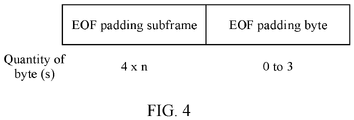
- an A-MPDU subframe whose EOF field is set to 1 and whose MPDU length field is set to 0 is used to indicate that padding after A-MPDU pre-EOF padding, and is referred to as an EOF padding subframe, where the EOF padding subframe is included in an end of frame padding field.
- the end of frame padding field includes at least one of the EOF padding subframe and an EOF padding byte.
- FIG. 4 shows a schematic diagram of a structure of an end of frame padding field. As shown in FIG. 4 , n is a non-negative integer.
- an A-MPDU subframe whose EOF field is set to 1 and whose MPDU length field is set to a non-zero value includes two cases.
- the A-MPDU subframe is included in a multi-traffic ID A-MPDU (Multi-TID A-MPDU) or a single-traffic ID A-MPDU (single-TID A-MPDU).
- a management frame may be considered as a specific data frame that carries a special traffic ID, for example, a traffic ID 15.
- the A-MPDU subframe is an only A-MPDU subframe of the traffic ID in the multi-TID A-MPDU or the single-TID A-MPDU, is used to solicit (solicit) a receive end to respond to single acknowledgment information, and may be included in an ACK frame, or may be included in acknowledgment information of multi-station block acknowledgment Multi-STA Block Ack.
- the A-MPDU subframe whose EOF field is set to 1 and whose MPDU length field is set to the non-zero value is included in an S-MPDU (or referred to as a VHT single A-MPDU), belongs to a special single MPDU, and is used to solicit (solicit) the receive end to respond to the single acknowledgment information.
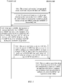
- FIG. 5 is a schematic flowchart of a data unit (a medium access control protocol data unit, MPDU) interaction method according to an embodiment of this application.
- a procedure of the interaction method includes the following steps.
- a transmit end sends a first aggregated media access control protocol data unit A-MPDU.
- the first A-MPDU includes at least one A-MPDU subframe.
- One A-MPDU subframe includes one MPDU. Therefore, each of the at least one A-MPDU subframe includes one MPDU. For example, a quantity of the at least one A-MPDU subframe is M, and M is a positive integer. One A-MPDU subframe includes one MPDU. Therefore, the M A-MPDU subframes include M MPDUs.
- One A-MPDU subframe further includes an MPDU delimiter and a padding field.
- the first A-MPDU may further include an end of frame padding field located after the at least one A-MPDU subframe.
- FIG. 4 for a structure of the end of frame padding field.
- the transmit end may encapsulate the first A-MPDU into a first physical layer protocol data unit PPDU (physical layer protocol data unit, PPDU) and send the first A-MPDU to a receive end.
- physical layer bits such as pre-FEC padding and/or tail bits (tail bits) padding may be padded as required after the first A-MPDU.
- An encoding method and encoding parameters that are used to encode the first A-MPDU in an encapsulation process are not limited in this implementation of this application. For example, a low density parity code (low density parity code, LDPC) and a binary convolutional code (Binary convolutional code, BCC) may be used for encoding.
- the encoding parameters used in step S101 may be referred to as pre-transmission encoding parameters.
- S102 Determine an MPDU that needs to be retransmitted in the first A-MPDU, where the MPDU that needs to be retransmitted is included in a first A-MPDU subframe in the first A-MPDU, the first A-MPDU subframe includes a first MPDU delimiter, and the first MPDU delimiter includes a first EOF field and a first MPDU length field.
- the transmit end determines the MPDU that needs to be retransmitted in the first A-MPDU, where the MPDU that needs to be retransmitted is included in the first A-MPDU subframe of the first A-MPDU.
- the first A-MPDU may further include another A-MPDU subframe.
- an MPDU in the another A-MPDU subframe does not need to be retransmitted.
- the transmit end may determine, in a plurality of manners, which MPDUs in a previously transmitted A-MPDU need to be retransmitted. For example, the transmit end may determine which previously transmitted MPDUs need to be retransmitted based on acknowledgment information sent by the receive end, or based on service requirements of the transmit end, or based on acknowledgment information sent by the receive end and an actual situation of the transmit end.
- the transmit end determines, based on the acknowledgment information fed back by the receive end, which MPDUs need to be retransmitted. Therefore, optionally, the acknowledgment information fed back by the receive end is used to indicate, to the transmit end, which MPDUs in the previously transmitted A-MPDU are successfully received.
- the receive end may use negative acknowledgment (NACK) information, or a bitmap in a block acknowledgment (Block Ack) frame, or a bitmap in a multi-STA block acknowledgment (Multi-STA Block Ack) frame to inform the transmit end of specific MPDUs that fail to be received or are successfully received.
- NACK negative acknowledgment
- Block Ack block acknowledgment
- Multi-STA Block Ack multi-STA block acknowledgment
- the MPDU that needs to be retransmitted may be an MPDU that is unsuccessfully received (that fails to be received) by the receive end in previous transmission.
- An MPDU that does not need to be retransmitted may be an MPDU that is successfully received (that succeeds to be received) by the receive end in the previous transmission, or an MPDU that is not correctly received and that does not need to be retransmitted again, for example, an MPDU whose actual effect time period ends.
- the method includes S102a: The receive end sends acknowledgment information fed back for the first A-MPDU, where the acknowledgment information is used to indicate whether the at least one MPDU in the first A-MPDU is successfully sent.
- the acknowledgment information may be acknowledgment (acknowledgment, ACK) or block acknowledgment (block acknowledgment, BA).
- the receive end receives the acknowledgment information.
- the transmit end determines, based on the acknowledgment information, which MPDUs in the first A-MPDU fail to be sent, to determine the MPDUs that need to be retransmitted. For example, N MPDUs in the M MPDUs of the first A-MPDU fail to be sent, where N is an integer greater than or equal to 1 and less than or equal to M. In this case, the transmit end determines that the N MPDUs need to be retransmitted.
- step S102 after determining the MPDUs that need to be retransmitted, the transmit end retransmits the MPDUs in a second A-MPDU.
- the transmit end sends the second A-MPDU, where the second A-MPDU includes a second A-MPDU subframe, the second A-MPDU subframe includes the MPDU that needs to be retransmitted and a second MPDU delimiter, and the second MPDU delimiter includes a second EOF field and a second MPDU length field.
- a value of the second EOF field is the same as a value of the first EOF field, and a value of the second MPDU length field is the same as a value of the second MPDU length field.
- the N MPDUs are separately included in N second A-MPDU subframes of the second A-MPDU.
- One second A-MPDU includes one MPDU that needs to be retransmitted.
- the second A-MPDU may further include another A-MPDU subframe.
- Each subframe in the second A-MPDU may further include an MPDU delimiter and a padding field.
- a structure of the MPDU delimiter refer to FIG. 3 ; and for a structure of the padding field, refer to FIG. 4 .
- the second MPDU delimiter is the same as the first MPDU delimiter, in other words, a value of any field in the second MPDU delimiter is the same as a value of a corresponding field in the first MPDU delimiter.
- the retransmitted MPDU includes a MAC header, and values of fields in the MAC header also needs to be set to be the same as values of fields in a MAC header of the MPDU in the first A-MPDU.
- the MPDU may further include an encryption header field, and a value of the encryption header field when the MPDU is retransmitted also needs to be the same as a value of the encryption header field when the MPDU is previously transmitted.
- the encryption header field is located after the MAC header field.
- encryption is performed by using a cipher-block chaining message authentication code (cipher-block chaining message authentication code, CBC-MAC) protocol (CBC-MAC protocol, CCMP), the encryption header is a CCMP header (CCMP Header), and the MPDU may be referred to as a CCMP MPDU, where the CCMP MPDU further includes a message integrity code (message integrity code, MIC) field, the CCMP header includes 8 bytes, and the MIC field includes 16 bytes.
- the CCMP header field includes a packet number (packet number, PN), an extended initialization vectors (extended initialization vectors, ExtIV) indication, and a key ID (Key ID) subfield.
- the encryption header is a GCMP header (GCMP Header), and the MPDU may be referred to as a GCMP MPDU, where the GCMP MPDU further includes a MIC field, the GCMP header includes 8 bytes, and the MIC field includes 16 bytes.
- the GCMP header includes a PN, an extended initialization vectors (extended initialization vectors, ExtIV) indication, and a key ID subfield. In the GCMP header, the ExtIV indication keeps being set to 1.
- the first A-MPDU subframe includes a first padding field
- the second A-MPDU subframe includes a second padding field
- a value of the first padding field is the same as a value of the second padding field.
- a value of a retry (retry) bit in a frame header of the MPDU that needs to be retransmitted in the second A-MPDU is the same as a value of a retry bit in a MAC header of the MPDU that needs to be retransmitted in the first A-MPDU.
- the value of the retry (retry) bit in the MAC header of the MPDU that needs to be retransmitted is set to 0.
- a value of a buffered traffic size field in the MAC header of the MPDU that needs to be retransmitted in the second A-MPDU is the same as a value of a buffered traffic size field in the MAC header of the MPDU that needs to be retransmitted in the first A-MPDU.
- the retry bit is included in a frame control field of the MAC header, and the buffered traffic size field may be included in an HT-Control field (referred to as an A-control field in the 802.11ax) or a QoS control field of the MAC header.
- the transmit end may encapsulate the second A-MPDU into a second physical layer protocol data unit PPDU, and send the second A-MPDU to the receive end.
- Parameters used to encode the second A-MPDU in step S103 are referred to as retransmission encoding parameters.
- the encoding method and encoding parameters used for encoding the second A-MPDU are the same as or have a preset relationship with the encoding method and the encoding parameters used for encoding the first A-MPDU.
- the encoding parameters include a bit rate and a generator polynomial matrix corresponding to the bit rate.
- the encoding parameters further include a puncturing pattern.
- that the retransmission encoding parameter is the same as the pre-transmission encoding parameter may mean that the bit rate and the generator polynomial matrix corresponding to the bit rate are the same.
- the encoding parameter includes the puncturing pattern, a retransmission puncturing pattern and a pre-transmission puncturing pattern are also the same.
- the retransmission encoding parameter has the preset relationship with the pre-transmission encoding parameter means that the bit rate, and the generator polynomial matrix corresponding to the bit rate are the same. If the encoding parameter includes the puncturing pattern, the retransmission puncturing pattern has a preset relationship with the pre-transmission puncturing pattern. A coded bit obtained in the retransmission puncturing pattern and a coded bit obtained in the pre-transmission puncturing pattern may be combined into a coded bit obtained in a new puncturing pattern.
- performing the LDPC encoding on the second A-MPDU subframe includes but is not limited to the following two manners:
- bits included in the second A-MPDU subframe are encoded as information bits.
- puncturing may be performed, and information bits may be punctured, or check bits may be punctured.
- performing the BCC encoding on the second A-MPDU subframe includes but is not limited to the following two manners:
- values of an MPDU delimiter and a padding field included in an A-MPDU subframe in which the retransmitted MPDU is located also need to be the same as values of an MPDU delimiter and a padding field of the previously transmitted MPDU, where a value of an EOF included in the MPDU delimiter field is the same as a value of an MPDU length subfield included in the MPDU delimiter field.
- S104 Perform combining and decoding or joint decoding on a log-likelihood ratio LLR of a coded bit corresponding to the first A-MPDU subframe and an LLR of a coded bit corresponding to the second A-MPDU subframe, to obtain the MPDU that needs to be retransmitted.
- the receive end performs combining and decoding or joint decoding on the LLR of the coded bit corresponding to the second A-MPDU subframe in the second A-MPDU and the LLR of the coded bit of the first A-MPDU subframe in the first A-MPDU, to obtain information bits of the A-MPDU subframes, so as to obtain the MPDU that needs to be retransmitted. In this way, the MPDU that is previously incorrectly transmitted is successfully received, to improve transmission reliability.
- the LDPC encoding is used, and for the HARQ CC, the receive end performs combining and decoding on an LLR of an LDPC codeword corresponding to the second A-MPDU subframe and an LLR of an LDPC codeword corresponding to the first A-MPDU subframe.
- the receive end performs joint decoding on the LLR of the LDPC codeword corresponding to the second A-MPDU subframe and the LLR of the LDPC codeword corresponding to the first A-MPDU subframe.
- the BCC encoding is used, and for the HARQ CC, the receive end performs combining and decoding on an LLR of a BCC coded bit corresponding to the second A-MPDU subframe and an LLR of a BCC coded bit corresponding to the first A-MPDU subframe.
- the receive end performs joint decoding on the LLR of the BCC coded bit corresponding to the second A-MPDU subframe and the LLR of the BCC coded bit corresponding to the first A-MPDU subframe.
- the second A-MPDU further includes a second end of frame padding field located after all second A-MPDU subframes
- the first A-MPDU further includes a first end of frame padding field located after the first A-MPDU subframe
- a value of the second end of frame padding field is the same as a value of the first end of frame padding field.
- a value of a physical layer padding bit padded after the second A-MPDU also needs to be the same as a value of a physical layer padding bit padded after the first A-MPDU last time.
- the first PPDU carrying the first A-MPDU subframe may further include first pre-FEC padding located after the first A-MPDU
- the second PPDU carrying the second A-MPDU subframe may include second pre-FEC padding located after the second A-MPDU, where the first pre-FEC padding is the same as the second pre-FEC padding.
- the first PPDU may further include a first tail bit located after the first A-MPDU
- the second PPDU may further include a second tail bit located after the second A-MPDU, where a value of the second tail bit is the same as a value of the first tail bit.
- the transmit end sets values of related fields in the A-MPDU subframe that includes the retransmitted MPDU to be the same as values of related fields in the A-MPDU subframe that includes the previously transmitted MPDU, so that the information bits are the same.
- the receive end can perform combining and decoding or joint decoding on an LLR of the coded bit of the previously transmitted A-MPDU subframe and an LLR of the coded bit of the currently retransmitted A-MPDU subframe, to improve transmission reliability and efficiency. Otherwise, because the information bits are different, combining and decoding or joint decoding cannot be performed on LLRs of coded bits of previously and currently transmitted A-MPDU subframes that include a same MPDU.
- the solutions in this embodiment of this application implement a HARQ mechanism applicable to a structure of an A-MPDU in a WLAN system.
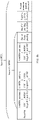
- FIG. 6a is a schematic diagram of a structure of a first A-MPDU
- FIG. 6b is a schematic diagram of a structure of a second A-MPDU.
- a transmit end sends a single-traffic ID S-MPDU (a first A-MPDU shown in FIG. 6a ) on a channel, where the S-MPDU includes an A-MPDU subframe 1.
- an MPDU in the A-MPDU subframe 1 fails to be transmitted.
- the MPDU is aggregated with other MPDUs of the same traffic ID (a second A-MPDU shown in FIG. 6b ) for sending.
- an EOF of the A-MPDU subframe 1 in the second A-MPDU subframe is set by using the existing 802.11ax protocol, the EOF needs to be set to 0.
- setting of the EOF of an MPDU delimiter of the A-MPDU subframe 1 in the second A-MPDU does not comply with setting of the 802.11ax protocol and a previous protocol, and a value of the EOF in the A-MPDU subframe 1 of the second A-MPDU is set to be the same as a value of an EOF in the A-MPDU subframe 1 of the first A-MPDU.
- a value of an MPDU length field in the MPDU delimiter of the A-MPDU subframe 1 in the second A-MPDU also needs to be the same as a value of an MPDU length field in an MPDU delimiter of the A-MPDU subframe 1 in the first A-MPDU.
- Reasons are as follows: Content of an MPDU included in a retransmitted A-MPDU subframe may be a part of a previously MPDU that fails to be transmitted. For example, in HARC CC transmission, different previously designed redundant versions of MPDUs are transmitted in each time of retransmission. During retransmission, a value of a padding field in the A-MPDU subframe 1 also needs to be the same as a value of a padding field in an A-MPDU subframe 1 that is incorrectly transmitted last time.
- FIG. 7a is a schematic diagram of a structure of another first A-MPDU
- FIG. 7b is a schematic diagram of a structure of another second A-MPDU.
- a transmit end sends a multiple traffic ID aggregated media access control data unit multi-TID A-MPDU (multiple traffic ID A-MPDU, multi-TID A-MPDU) on a channel, where traffic IDs include a TID 1 and a TID 2.
- the multi-TID A-MPDU (a first A-MPDU) is shown as an example in the following FIG. 7a . It is learned, based on acknowledgment information fed back by a receive end, that an A-MPDU subframe 1 in a first A-MPDU fails, and is aggregated with another MPDU whose traffic ID is the TID 1 for sending during next retransmission.
- the second A-MPDU is shown as an example in the FIG.
- setting of an EOF of an MPDU delimiter of the A-MPDU subframe 1 in the second A-MPDU does not meet setting of the 802.11ax and a previous protocol, but in order to support HARQ transmission, a value of the EOF in the A-MPDU subframe 1 of the second A-MPDU is set to be the same as a value of an EOF in the A-MPDU subframe 1 of the first A-MPDU.
- a value of an MPDU length field in the MPDU delimiter of the A-MPDU subframe 1 in the second A-MPDU also needs to be the same as a value of an MPDU length field in an MPDU delimiter of the A-MPDU subframe 1 in the first A-MPDU.
- Reasons are as follows: Content of an MPDU included in a retransmitted A-MPDU subframe may be a part of a previously MPDU that fails to be transmitted. For example, in HARC CC transmission, different previously designed redundant versions of MPDUs are transmitted in each time of retransmission. During retransmission, a value of a padding field in the A-MPDU subframe 1 also needs to be the same as a value of a padding field in an A-MPDU subframe 1 that is incorrectly transmitted last time.
- FIG. 6a, FIG. 6b, FIG. 7a , and FIG. 7b show cases in which only one MPDU is retransmitted.
- the solutions in the embodiments of this application may also be applicable to a case in which a plurality of MPDUs are retransmitted. This is not limited to the examples of FIG. 6a, FIG. 6b, FIG. 7a , and FIG. 7b .
- FIG. 8a is a schematic diagram of a first PPDU
- FIG. 8b is a schematic diagram of a second PPDU.
- a second A-MPDU includes all MPDUs in the first A-MPDU.
- a value of an end of frame padding field of the second A-MPDU also needs to be the same as a value of an end of frame padding field of the first A-MPDU.
- a value of a physical layer padding bit that may be included after the second A-MPDU may also need to be the same as a value of a physical layer padding bit included after the first A-MPDU.
- the value of the physical layer padding bit is not specified, to avoid a problem in which combining and decoding or joint decoding cannot be performed that may be caused in HARQ transmission. Therefore, in this application, the value of the physical layer padding bit that may be included after the second A-MPDU also needs to be the same as the value of the physical layer padding bit included after the first A-MPDU.
- the first PPDU may include pre-FEC padding and/or packet extension (packet extension).
- Duration of the pre-FEC padding may be a quarter (1/4) of OFDM symbol duration, a half (1/2) of OFDM symbol duration, or three-quarters (3/4) of OFDM symbol duration; and duration of the packet extension may be 4 ⁇ s, 8 ⁇ s, or 16 ⁇ s.
- a value of a pre-FEC padding field included in the second PPDU also needs to be set to be the same as a value of the pre-FEC padding in the first PPDU.
- a value of an EOF and a value of an MPDU length field of an A-MPDU subframe to which each retransmitted MPDU belongs also need to be set to be the same as those before.
- a value of an EOF and a value of an MPDU length field of an A-MPDU subframe to which each retransmitted MPDU belongs also need to be set to be the same as those before.
- control information carried in a MAC header of a previously transmitted MPDU and control information carried in a MAC header of a subsequently retransmitted MPDU may be set differently. For example, for setting of values of retry bits of frame control fields in the MAC headers, during previous transmission, the value of the retry bit is set to 0, and during retransmission, the value of the retry bit is set to 1.
- a buffered traffic size field carried in an HT-control field (referred to as an A-control field in the 802.11ax) or a QoS control field in the MAC header is further used as an example.
- the buffered traffic size field indicated by the HT-control field in the MAC header (referred to as the A-control field in the 802.11ax) or the QoS control field may be X bytes; but during retransmission, the buffered traffic size field indicated by the HT-control field (referred to as the A-control field in the 802.11ax) or the QoS control field in the MAC header may be Y bytes.
- values of some fields may be set to be different from values of the fields when the MPDU is previously transmitted.
- the fields need to be set to have the same values, to ensure that a value of a retransmitted information bit is the same as a value of a previously transmitted information bit, and to ensure that the receive end can implement joint decoding or combining and decoding, to implement the HARQ mechanism.
- FIG. 9 is a schematic diagram of a structure of a sending apparatus according to an embodiment of this application, where the sending apparatus may be applied to a transmit end or a chip in a transmit end.
- the sending apparatus 900 includes a processing module 901, a sending module 902, and a receiving module 903.
- the sending apparatus may be configured to perform any function of the foregoing transmit end, and the following is used as examples.
- the processing module 901 is configured to determine an MPDU that needs to be retransmitted in a first A-MPDU. For example, the processing module 901 is configured to perform the foregoing S102, or the processing module 901 is further configured to encode the first A-MPDU, or the processing module 901 is further configured to encode a second A-MPDU.
- the sending module 902 is configured to send the first A-MPDU and the second A-MPDU, for example, the sending module 902 is configured to perform S101 and S103.
- the receiving module 903 is configured to receive acknowledgment feedback information, where the acknowledgment feedback information is used to indicate which MPDUs in the first A-MPDU are not successfully received, for example, the receiving module 903 is configured to perform S 102a.
- the sending apparatus 900 further includes a storage module 904, where the storage module 904 is configured to store instructions.
- the sending apparatus 900 is the chip in the transmit end, the sending module is an input interface, the receiving module is an output interface, and the processing module is a processing circuit, where the input interface and the output interface are used to implement signaling or data interaction between the chip and another component.
- the processing circuit is configured to implement processing on the signaling or data, for example, the processing circuit is configured to send (output) the first A-MPDU and the second A-MPDU, and is configured to receive (input) the acknowledgment information.
- the processing circuit is configured to determine, based on the acknowledgment information, which MPDUs in the first A-MPDU need to be retransmitted.
- An apparatus in which the chip is installed may implement the method and functions of the transmit end in the foregoing embodiments.
- the data transmission apparatus shown in FIG. 9 is used as an example to describe modules in a data transmission apparatus used for the transmit end.
- FIG. 10 is a schematic diagram of a structure of a receiving apparatus according to an embodiment of this application, where the receiving apparatus 1000 may be applied to a receive end or a chip in a receive end.
- the receiving apparatus 1000 includes a processing module 1001, a sending module 1002, and a receiving module 1003.
- the receiving apparatus may be configured to perform any function of the foregoing receive end, and the following is used as examples.
- the processing module 1001 is configured to determine which MPDUs in a first A-MPDU are successfully sent.
- the processing module 1001 is further configured to perform combining and decoding or joint decoding on an LLR of a coded bit of a first A-MPDU subframe and an LLR of a coded bit of a second A-MPDU subframe, to obtain a retransmitted MPDU.
- the processing module 1001 is configured to perform the foregoing S104.
- the sending module 1002 is configured to send acknowledgment information, for example, the sending module 1002 is configured to perform S102a, where the acknowledgment feedback is used to indicate which MPDUs in the first A-MPDU are not successfully received.
- the receiving module 1003 is configured to receive the first A-MPDU and a second A-MPDU, for example, the receiving module 1003 is configured to receive information sent in S102 and S103.
- the receiving apparatus 1000 further includes a storage module 1004, where the storage module 1004 is configured to store an LLR corresponding to a pre-transmission coded bit, and optionally, the storage module 1004 is further configured to store instructions.
- the receiving apparatus 1000 is the chip in the receive end
- the sending module is an input interface
- the receiving module is an output interface
- the processing module is a processing circuit, where the input interface and the output interface are used to implement signaling or data interaction between the chip and another component.
- the processing circuit is configured to implement processing on the signaling or data, for example, the processing circuit is configured to receive (input) the first A-MPDU and the second A-MPDU, and configured to send (output) the acknowledgment information.
- the processing circuit is configured to determine, based on the acknowledgment information, which MPDUs in the first A-MPDU are successfully sent and which MPDUs in the first A-MPDU fail to be sent.
- An apparatus in which the chip is installed may implement the method and functions of the receive end in the foregoing embodiments.
- the data transmission apparatus shown in FIG. 10 is used as an example to describe modules in a data transmission apparatus used for the receive end.
- the sending apparatus (used for the transmit end) or the receiving apparatus (used for the receive end) provided in the embodiments of this application may be implemented in a plurality of product forms.
- the sending apparatus or the receiving apparatus may be configured as a general processing system.
- the sending apparatus or the receiving apparatus may be implemented by a general bus architecture.
- the sending apparatus or the receiving apparatus may be implemented by using an application-specific integrated circuit (application-specific integrated circuit, ASIC).
- ASIC application-specific integrated circuit
- FIG. 11 is a schematic block diagram of a sending apparatus 1100 according to an embodiment of this application.
- the apparatus 1100 in this embodiment of this application may be the transmit end in any one of the foregoing method embodiments, or may be one or more chips in the transmit end.
- the apparatus 1100 may be configured to perform some or all functions of the transmit end in the foregoing method embodiments.
- the apparatus 1100 may include a processor 1110, a baseband circuit 1130, a radio frequency circuit 1140, and an antenna 1150.
- the apparatus 1100 may further include a memory 1120.
- Components of the apparatus 1100 are coupled together through a bus 1160.
- the bus system 1160 includes a power bus, a control bus, and a status signal bus.
- various types of buses in the figure are marked as the bus system 1160.
- the processor 1110 may be configured to control the transmit end, and configured to perform processing performed by the transmit end in the foregoing embodiments.
- the processor 1110 may perform a processing process related to the transmit end in the foregoing method embodiments and/or configured to perform another process of the technology described in this application. Further, the processor 1110 may run an operating system, be responsible for managing the bus, and execute a program or instructions stored in the memory.
- the baseband circuit 1130, the radio frequency circuit 1140, and the antenna 1150 may be configured to support information receiving and sending between the transmit end and the receive end in the foregoing embodiments, so as to support wireless communication between the transmit end and the receive end.
- a first A-MPDU or a second A-MPDU is processed by the processor 1110; and after the first A-MPDU or the second A-MPDU is encapsulated into an A-MPDU according to a protocol by using the baseband circuit 1130, baseband processing such as scrambling and encoding is performed on the A-MPDU obtained through encapsulation.
- the radio frequency circuit 1140 further performs radio frequency processing such as analog conversion, filtering, amplification, and up-conversion on an A-MPDU obtained through baseband processing, and then transmits an A-MPDU obtained through radio frequency processing through the antenna 1150.
- acknowledgment feedback information sent by the receive end is received through the antenna 1150, undergoes processing such as filtering, amplification, down-conversion, digitization, and the like performed by the radio frequency circuit 1140, undergoes baseband processing such as decoding and protocol-based data decapsulation performed by the baseband circuit 1130, and is processed by the processor 1110, to recover the acknowledgment feedback information sent by the receive end.
- the memory 1120 may be configured to store program code and data of the transmit end.
- the memory 1120 may be the storage module 1130 in FIG. 11 .
- the baseband circuit 1130, the radio frequency circuit 1140, and the antenna 1150 may be further configured to support communication between the transmit end and another network entity, for example, communication between the transmit end and a network element on a core network side.
- the memory 1120 is separated from the processor 1110.
- the memory 1120 may include a transmission cable and/or a computer product separated from a wireless node.
- the media may be accessed by the processor 1110 through the bus interface 1160.
- the memory 1120 or any portion thereof may be integrated into the processor 1110, for example, the memory 1120 or any portion thereof may be a cache and/or a general purpose register.
- FIG. 11 shows only a simplified design of the transmit end.
- the transmit end may include any quantity of transmitters, receivers, processors, memories, and the like, and all transmit ends that can implement the present invention fall within the protection scope of the present invention.
- FIG. 12 is a schematic block diagram of a receiving apparatus 1200 according to an embodiment of this application.
- the apparatus 1200 in this embodiment of this application may be the receive end in any one of the foregoing method embodiments, or may be one or more chips in the receive end.
- the apparatus 1200 may be configured to perform some or all functions of the receive end in the foregoing method embodiments.
- the apparatus 1200 may include a processor 1210, a baseband circuit 1230, a radio frequency circuit 1240, and an antenna 1250.
- the apparatus 1200 may further include a memory 1220.
- Components of the apparatus 1200 are coupled together through a bus 1260.
- the bus system 1260 includes a power bus, a control bus, and a status signal bus.
- various types of buses in the figure are marked as the bus system 1260.
- the processor 1210 may be configured to control the receive end, and configured to perform processing performed by the receive end in the foregoing embodiments.
- the processor 1210 may perform a processing process related to the transmit end in the foregoing method embodiments and/or configured to perform another process of the technology described in this application. Further, the processor 1210 may run an operating system, be responsible for managing the bus, and execute a program or instructions stored in the memory.
- the baseband circuit 1230, the radio frequency circuit 1240, and the antenna 1250 may be configured to support information receiving and sending between the receive end and the transmit end in the foregoing embodiments, to support wireless communication between the receive end and the transmit end.
- a signal sent by the transmit end is received through the antenna 1250, undergoes processing such as filtering, amplification, down-conversion, and digitization performed by the radio frequency circuit, and undergoes baseband processing such as decoding and protocol-based data decapsulation performed by the baseband circuit.
- the processor 1210 performs processing on the signal, to recover service data and signaling information that are sent by the transmit end.
- the receive end decodes and decapsulates a received PPDU to obtain an A-MPDU, and then the A-MPDU is parsed by using the processor to obtain an MPDU.
- acknowledgment feedback information of the receive end may be processed by the processor 1210, undergoes baseband processing such as protocol-based encapsulation and encoding performed by the baseband circuit 1230, undergoes radio frequency processing such as analog conversion, filtering, amplification, and up-conversion performed by the radio frequency circuit 1240, and is transmitted through the antenna 1250.
- the memory 1220 may be configured to store program code and data of the transmit end, and the memory 1220 may be a storage module. It may be understood that the baseband circuit 1230, the radio frequency circuit 1240, and the antenna 1250 may further be configured to support the receive end to communicate with another network entity.
- FIG. 12 shows only a simplified design of the receive end.
- the receive end may include any quantity of transmitters, receivers, processors, memories, and the like, and all receive ends that can implement the present invention fall within the protection scope of the present invention.
- the processor in each of the apparatus 1100 and the apparatus 1200 may be a general-purpose processor, for example, a general-purpose central processing unit (CPU), a network processor (Network Processor, NP for short), a microprocessor; or may be an application-specific integrated circuit (application-specific integrated circuit, ASIC for short), or one or more integrated circuits configured to control program execution in the solutions of this application.
- CPU general-purpose central processing unit
- NP Network Processor
- ASIC application-specific integrated circuit
- the processor may be alternatively a digital signal processor (Digital Signal Processor, DSP for short), a field programmable gate array (Field Programmable Gate Array, FPGA for short) or other programmable logic device, discrete gate or transistor logic device, or a discrete hardware component.
- a controller/the processor may be a combination of processors implementing a computing function, for example, a combination of one or more microprocessors, or a combination of the DSP and the microprocessor.
- the processor usually performs logical and arithmetic operations according to program instructions stored in the memory.
- Each of the memories in the apparatus 1100 and the apparatus 1200 may further store an operating system and another application program.
- the program may include program code, and the program code includes computer operation instructions.
- the memory may be a read-only memory (read-only memory, ROM for short), another type of static storage device that can store static information and instructions, a random access memory (random access memory, RAM for short), another type of dynamic storage device that can store information and instructions, a disk memory, or the like.
- the memory may be a combination of the foregoing storage types.
- a computer-readable storage medium/the memory may be located in the processor, or may be located outside the processor, or distributed in a plurality of entities including a processor or a processing circuit.
- the computer-readable storage medium/memory may be specifically embodied in a computer program product.
- the computer program product may include a computer-readable medium in a packaging material.
- An embodiment of this application further provides a chip system.
- the chip system includes a processor and is configured to support a transmit end or a second receive end to implement the function in any of the foregoing embodiments, for example, generate or process data and/or information in the foregoing methods.
- the chip system may further include a memory.
- the memory is configured to store program instructions and data that are necessary for the transmit end or the receive end.
- the chip system may include a chip, or may include a chip and another discrete component.
- An embodiment of this application further provides a processor, where the processor is configured to be coupled to a memory, and to perform a method and a function related to a transmit end or a receive end in any one of the foregoing embodiments.
- the processor includes a processing circuit and a communication interface.
- An embodiment of this application further provides a computer program product including instructions. When the computer program product runs on a computer, the computer is enabled to perform a method and a function that are related to a transmit end or a receive end in any one of the foregoing embodiments.
- An embodiment of this application further provides an apparatus, where the apparatus is configured to perform a method and a function of a receive end or a transmit end in any one of the foregoing embodiments.
- An embodiment of this application further provides a wireless communication system. The system includes at least one transmit end and at least one receive end in any one of the foregoing embodiments.
- the disclosed system, apparatus, and method may be implemented in other manners.
- the described apparatus embodiment is merely an example.
- division into units is merely a logical function division and may be other division in actual implementation.
- a plurality of units or components may be combined or integrated into another system, or some features may be ignored or not performed.
- the displayed or discussed mutual couplings or direct couplings or communication connections may be implemented through some interfaces, and the indirect couplings or communication connections between the apparatuses or units may be implemented in electronic, mechanical, or other forms.
- the data transmission apparatus may alternatively be implemented by using the following: a field programmable gate array (Field Programmable Gate Array, FPGA), a programmable logic device (Programmable Logic Device, PLD), a controller, a state machine, gate logic, a discrete hardware component, any other suitable circuit, or any combination of circuits that can perform various functions described in this application.
- a field programmable gate array Field Programmable Gate Array, FPGA
- PLD programmable logic device
- controller a state machine
- gate logic a discrete hardware component
- any other suitable circuit any combination of circuits that can perform various functions described in this application.
- All or some of the foregoing embodiments may be implemented by using software, hardware, firmware, or any combination thereof.
- software is used to implement the embodiments, all or some of the embodiments may be implemented in a form of a computer program product.
- the computer program product includes one or more computer instructions. When the computer program instructions are loaded and executed on the computer, procedures or functions according to this application are all or partially generated.
- the computer may be a general-purpose computer, a dedicated computer, a computer network, or another programmable apparatus.
- the computer instructions may be stored in a computer-readable storage medium or may be transmitted from a computer-readable storage medium to another computer-readable storage medium.
- the computer instructions may be transmitted from a website, computer, server, or data center to another website, computer, server, or data center in a wired (for example, a coaxial cable, an optical fiber, or a digital subscriber line) or wireless (for example, infrared, radio, or microwave) manner.
- the computer-readable storage medium may be any usable medium accessible by the computer, or a data storage device, for example, a server or a data center integrating one or more usable media.
- the usable medium may be a magnetic medium (for example, a floppy disk, a hard disk, or a magnetic tape), an optical medium (for example, a DVD), a semiconductor medium (for example, a solid state disk, Solid State Disk), or the like.
Landscapes
- Engineering & Computer Science (AREA)
- Computer Networks & Wireless Communication (AREA)
- Signal Processing (AREA)
- Mobile Radio Communication Systems (AREA)
- Detection And Prevention Of Errors In Transmission (AREA)
Applications Claiming Priority (2)
| Application Number | Priority Date | Filing Date | Title |
|---|---|---|---|
| CN201910657446.4A CN112243265B (zh) | 2019-07-19 | 2019-07-19 | 数据单元的发送方法、接收方法及装置 |
| PCT/CN2020/102263 WO2021013026A1 (zh) | 2019-07-19 | 2020-07-16 | 数据单元的发送方法、接收方法及装置 |
Publications (2)
| Publication Number | Publication Date |
|---|---|
| EP3996300A1 true EP3996300A1 (de) | 2022-05-11 |
| EP3996300A4 EP3996300A4 (de) | 2022-08-03 |
Family
ID=74167886
Family Applications (1)
| Application Number | Title | Priority Date | Filing Date |
|---|---|---|---|
| EP20844140.2A Pending EP3996300A4 (de) | 2019-07-19 | 2020-07-16 | Verfahren zum senden und empfangen von dateneinheiten sowie vorrichtungen |
Country Status (4)
| Country | Link |
|---|---|
| US (2) | US12126444B2 (de) |
| EP (1) | EP3996300A4 (de) |
| CN (2) | CN119136251A (de) |
| WO (1) | WO2021013026A1 (de) |
Families Citing this family (7)
| Publication number | Priority date | Publication date | Assignee | Title |
|---|---|---|---|---|
| WO2021046772A1 (zh) * | 2019-09-11 | 2021-03-18 | 北京小米移动软件有限公司 | 数据包传输方法及装置 |
| US11924911B2 (en) * | 2020-05-22 | 2024-03-05 | Mediatek Singapore Pte. Ltd. | Extreme-high-throughput fast initial link setup support in multi-link operation in wireless communications |
| CN116320049B (zh) * | 2021-03-30 | 2023-11-07 | 华为技术有限公司 | 用于包扩展的方法、设备和存储介质 |
| WO2023031998A1 (ja) * | 2021-08-30 | 2023-03-09 | 日本電信電話株式会社 | 送信局及び受信局 |
| CN117134859A (zh) * | 2022-05-20 | 2023-11-28 | 中兴通讯股份有限公司 | 数据处理方法及电子设备、计算机可读存储介质 |
| EP4591480A1 (de) * | 2022-09-19 | 2025-07-30 | Sony Group Corporation | Kommunikationsvorrichtungen und -verfahren |
| US20250337437A1 (en) * | 2024-04-29 | 2025-10-30 | Avago Technologies International Sales Pte. Limited | SYSTEMS FOR AND METHODS FOR LARGE PACKET SUPPORT OVER Wi-Fi |
Family Cites Families (14)
| Publication number | Priority date | Publication date | Assignee | Title |
|---|---|---|---|---|
| US9300602B2 (en) * | 2012-11-02 | 2016-03-29 | Qualcomm Incorporated | Method, device, and apparatus for error detection and correction in wireless communications |
| CN103701574B (zh) * | 2013-11-27 | 2018-03-09 | 广西大学 | 一种数据发送以及重传方法 |
| US9876614B1 (en) * | 2014-01-20 | 2018-01-23 | Marvell International Ltd. | Hybrid automatic repeat request for wireless local area network |
| US11309998B2 (en) * | 2014-02-03 | 2022-04-19 | Nxp Usa, Inc. | Hybrid automatic repeat request for wireless local area network |
| CN111510257B (zh) * | 2014-03-17 | 2023-06-30 | 交互数字专利控股公司 | 用于wifi的接收失败识别和修复的方法 |
| US10129001B2 (en) * | 2015-08-14 | 2018-11-13 | Newracom, Inc. | Block acknowledgment for multi-user transmissions in WLAN systems |
| CN107771376B (zh) * | 2015-09-08 | 2021-07-23 | Lg电子株式会社 | 无线通信系统中发送数据的方法及其设备 |
| CN105471549B (zh) * | 2015-11-17 | 2018-09-11 | 西安电子科技大学 | 基于a-mpdu子帧位置信息控制的块确认系统及方法 |
| EP3562203A4 (de) * | 2016-12-21 | 2020-09-02 | Wilus Institute of Standards and Technology Inc. | Aggregierte mpdu, verfahren zum senden von antwortframes an diese und drahtloskommunikationsendgerät damit |
| US20180254861A1 (en) * | 2017-03-03 | 2018-09-06 | Qualcomm Incorporated | Ambiguous confirmation message resolution |
| CN107070599B (zh) * | 2017-04-06 | 2019-11-15 | 中国人民解放军理工大学 | 一种长距离链路变速率选择重传方法 |
| US20210075542A1 (en) * | 2019-09-05 | 2021-03-11 | Apple Inc. | Phy-based hybrid automatic repeat request (harq) |
| US11509419B2 (en) * | 2019-09-25 | 2022-11-22 | Qualcomm Incorporated | Acknowledgement and retransmission techniques utilizing secondary wireless channel |
| US12574151B2 (en) * | 2021-10-29 | 2026-03-10 | Senscomm Semiconductor Co., Ltd. | HARQ and link adaptation in wireless communication system |
-
2019
- 2019-07-19 CN CN202411322723.3A patent/CN119136251A/zh active Pending
- 2019-07-19 CN CN201910657446.4A patent/CN112243265B/zh active Active
-
2020
- 2020-07-16 WO PCT/CN2020/102263 patent/WO2021013026A1/zh not_active Ceased
- 2020-07-16 EP EP20844140.2A patent/EP3996300A4/de active Pending
-
2022
- 2022-01-19 US US17/579,195 patent/US12126444B2/en active Active
-
2024
- 2024-09-20 US US18/892,035 patent/US20250088312A1/en active Pending
Also Published As
| Publication number | Publication date |
|---|---|
| CN112243265A (zh) | 2021-01-19 |
| WO2021013026A1 (zh) | 2021-01-28 |
| US20250088312A1 (en) | 2025-03-13 |
| US12126444B2 (en) | 2024-10-22 |
| CN112243265B (zh) | 2024-10-15 |
| CN119136251A (zh) | 2024-12-13 |
| US20220149991A1 (en) | 2022-05-12 |
| EP3996300A4 (de) | 2022-08-03 |
Similar Documents
| Publication | Publication Date | Title |
|---|---|---|
| US12126444B2 (en) | Apparatus for retransmission of a media access control protocol data unit (MPDU) of an aggregated media access control protocol data unit (A-MPDU) | |
| US12267163B2 (en) | Retransmitted data sending method, retransmitted data receiving method, and apparatus | |
| US20220140952A1 (en) | Systems and methods for smart harq for wifi | |
| US11588585B2 (en) | Methods and apparatus for transmitting information on two PDSCHs | |
| EP3968550B1 (de) | Verfahren und vorrichtung zum senden und empfangen von weiterleitungsdaten | |
| EP3657713B1 (de) | Kommunikationsverfahren und -vorrichtung | |
| JP4794522B2 (ja) | 直交周波数分割多元接続の無線通信ネットワークの局間のチャネルにおけるハイブリッド自動繰返し要求動作を可能にする方法及びシステム | |
| US11309998B2 (en) | Hybrid automatic repeat request for wireless local area network | |
| US20250203357A1 (en) | Communication method and device in wireless local area network | |
| WO2021047657A1 (zh) | 重传数据的方法和通信装置 | |
| US12166576B2 (en) | Information processing device and information processing method | |
| US12244325B2 (en) | Information processing device, encoding method, and decoding method | |
| EP3821552B1 (de) | Vorrichtung und verfahren zur unterstützung von harq für wlan | |
| CN115336210B (zh) | 用于码字传输的方法和系统 | |
| US20230327800A1 (en) | Information processing device and decoding method |
Legal Events
| Date | Code | Title | Description |
|---|---|---|---|
| STAA | Information on the status of an ep patent application or granted ep patent |
Free format text: STATUS: THE INTERNATIONAL PUBLICATION HAS BEEN MADE |
|
| PUAI | Public reference made under article 153(3) epc to a published international application that has entered the european phase |
Free format text: ORIGINAL CODE: 0009012 |
|
| STAA | Information on the status of an ep patent application or granted ep patent |
Free format text: STATUS: REQUEST FOR EXAMINATION WAS MADE |
|
| 17P | Request for examination filed |
Effective date: 20220207 |
|
| AK | Designated contracting states |
Kind code of ref document: A1 Designated state(s): AL AT BE BG CH CY CZ DE DK EE ES FI FR GB GR HR HU IE IS IT LI LT LU LV MC MK MT NL NO PL PT RO RS SE SI SK SM TR |
|
| A4 | Supplementary search report drawn up and despatched |
Effective date: 20220705 |
|
| RIC1 | Information provided on ipc code assigned before grant |
Ipc: H04L 1/18 20060101ALI20220629BHEP Ipc: H04L 1/16 20060101ALI20220629BHEP Ipc: H04L 1/00 20060101AFI20220629BHEP |
|
| DAV | Request for validation of the european patent (deleted) | ||
| DAX | Request for extension of the european patent (deleted) | ||
| STAA | Information on the status of an ep patent application or granted ep patent |
Free format text: STATUS: EXAMINATION IS IN PROGRESS |
|
| 17Q | First examination report despatched |
Effective date: 20250715 |
|
| GRAP | Despatch of communication of intention to grant a patent |
Free format text: ORIGINAL CODE: EPIDOSNIGR1 |
|
| STAA | Information on the status of an ep patent application or granted ep patent |
Free format text: STATUS: GRANT OF PATENT IS INTENDED |
|
| INTG | Intention to grant announced |
Effective date: 20251114 |
|
| GRAJ | Information related to disapproval of communication of intention to grant by the applicant or resumption of examination proceedings by the epo deleted |
Free format text: ORIGINAL CODE: EPIDOSDIGR1 |
|
| STAA | Information on the status of an ep patent application or granted ep patent |
Free format text: STATUS: EXAMINATION IS IN PROGRESS |
|
| RAP1 | Party data changed (applicant data changed or rights of an application transferred) |
Owner name: NOKIA TECHNOLOGIES OY |
|
| GRAP | Despatch of communication of intention to grant a patent |
Free format text: ORIGINAL CODE: EPIDOSNIGR1 |
|
| STAA | Information on the status of an ep patent application or granted ep patent |
Free format text: STATUS: GRANT OF PATENT IS INTENDED |
|
| INTC | Intention to grant announced (deleted) | ||
| INTG | Intention to grant announced |
Effective date: 20260327 |