EP3998548B1 - Verfahren und vorrichtung zur anzeige einer punktwolke - Google Patents
Verfahren und vorrichtung zur anzeige einer punktwolke Download PDFInfo
- Publication number
- EP3998548B1 EP3998548B1 EP20858328.6A EP20858328A EP3998548B1 EP 3998548 B1 EP3998548 B1 EP 3998548B1 EP 20858328 A EP20858328 A EP 20858328A EP 3998548 B1 EP3998548 B1 EP 3998548B1
- Authority
- EP
- European Patent Office
- Prior art keywords
- point cloud
- vehicle
- target object
- describe
- obstacle
- Prior art date
- Legal status (The legal status is an assumption and is not a legal conclusion. Google has not performed a legal analysis and makes no representation as to the accuracy of the status listed.)
- Active
Links
Images


Classifications
-
- G—PHYSICS
- G06—COMPUTING OR CALCULATING; COUNTING
- G06T—IMAGE DATA PROCESSING OR GENERATION, IN GENERAL
- G06T19/00—Manipulating three-dimensional [3D] models or images for computer graphics
-
- B—PERFORMING OPERATIONS; TRANSPORTING
- B60—VEHICLES IN GENERAL
- B60K—ARRANGEMENT OR MOUNTING OF PROPULSION UNITS OR OF TRANSMISSIONS IN VEHICLES; ARRANGEMENT OR MOUNTING OF PLURAL DIVERSE PRIME-MOVERS IN VEHICLES; AUXILIARY DRIVES FOR VEHICLES; INSTRUMENTATION OR DASHBOARDS FOR VEHICLES; ARRANGEMENTS IN CONNECTION WITH COOLING, AIR INTAKE, GAS EXHAUST OR FUEL SUPPLY OF PROPULSION UNITS IN VEHICLES
- B60K35/00—Instruments specially adapted for vehicles; Arrangement of instruments in or on vehicles
- B60K35/10—Input arrangements, i.e. from user to vehicle, associated with vehicle functions or specially adapted therefor
-
- B—PERFORMING OPERATIONS; TRANSPORTING
- B60—VEHICLES IN GENERAL
- B60K—ARRANGEMENT OR MOUNTING OF PROPULSION UNITS OR OF TRANSMISSIONS IN VEHICLES; ARRANGEMENT OR MOUNTING OF PLURAL DIVERSE PRIME-MOVERS IN VEHICLES; AUXILIARY DRIVES FOR VEHICLES; INSTRUMENTATION OR DASHBOARDS FOR VEHICLES; ARRANGEMENTS IN CONNECTION WITH COOLING, AIR INTAKE, GAS EXHAUST OR FUEL SUPPLY OF PROPULSION UNITS IN VEHICLES
- B60K35/00—Instruments specially adapted for vehicles; Arrangement of instruments in or on vehicles
- B60K35/20—Output arrangements, i.e. from vehicle to user, associated with vehicle functions or specially adapted therefor
- B60K35/21—Output arrangements, i.e. from vehicle to user, associated with vehicle functions or specially adapted therefor using visual output, e.g. blinking lights or matrix displays
- B60K35/22—Display screens
-
- B—PERFORMING OPERATIONS; TRANSPORTING
- B60—VEHICLES IN GENERAL
- B60K—ARRANGEMENT OR MOUNTING OF PROPULSION UNITS OR OF TRANSMISSIONS IN VEHICLES; ARRANGEMENT OR MOUNTING OF PLURAL DIVERSE PRIME-MOVERS IN VEHICLES; AUXILIARY DRIVES FOR VEHICLES; INSTRUMENTATION OR DASHBOARDS FOR VEHICLES; ARRANGEMENTS IN CONNECTION WITH COOLING, AIR INTAKE, GAS EXHAUST OR FUEL SUPPLY OF PROPULSION UNITS IN VEHICLES
- B60K35/00—Instruments specially adapted for vehicles; Arrangement of instruments in or on vehicles
- B60K35/85—Arrangements for transferring vehicle- or driver-related data
-
- G—PHYSICS
- G01—MEASURING; TESTING
- G01S—RADIO DIRECTION-FINDING; RADIO NAVIGATION; DETERMINING DISTANCE OR VELOCITY BY USE OF RADIO WAVES; LOCATING OR PRESENCE-DETECTING BY USE OF THE REFLECTION OR RERADIATION OF RADIO WAVES; ANALOGOUS ARRANGEMENTS USING OTHER WAVES
- G01S17/00—Systems using the reflection or reradiation of electromagnetic waves other than radio waves, e.g. lidar systems
- G01S17/02—Systems using the reflection of electromagnetic waves other than radio waves
- G01S17/06—Systems determining position data of a target
- G01S17/42—Simultaneous measurement of distance and other co-ordinates
-
- G—PHYSICS
- G01—MEASURING; TESTING
- G01S—RADIO DIRECTION-FINDING; RADIO NAVIGATION; DETERMINING DISTANCE OR VELOCITY BY USE OF RADIO WAVES; LOCATING OR PRESENCE-DETECTING BY USE OF THE REFLECTION OR RERADIATION OF RADIO WAVES; ANALOGOUS ARRANGEMENTS USING OTHER WAVES
- G01S17/00—Systems using the reflection or reradiation of electromagnetic waves other than radio waves, e.g. lidar systems
- G01S17/02—Systems using the reflection of electromagnetic waves other than radio waves
- G01S17/50—Systems of measurement based on relative movement of target
- G01S17/58—Velocity or trajectory determination systems; Sense-of-movement determination systems
-
- G—PHYSICS
- G01—MEASURING; TESTING
- G01S—RADIO DIRECTION-FINDING; RADIO NAVIGATION; DETERMINING DISTANCE OR VELOCITY BY USE OF RADIO WAVES; LOCATING OR PRESENCE-DETECTING BY USE OF THE REFLECTION OR RERADIATION OF RADIO WAVES; ANALOGOUS ARRANGEMENTS USING OTHER WAVES
- G01S17/00—Systems using the reflection or reradiation of electromagnetic waves other than radio waves, e.g. lidar systems
- G01S17/88—Lidar systems specially adapted for specific applications
- G01S17/89—Lidar systems specially adapted for specific applications for mapping or imaging
-
- G—PHYSICS
- G01—MEASURING; TESTING
- G01S—RADIO DIRECTION-FINDING; RADIO NAVIGATION; DETERMINING DISTANCE OR VELOCITY BY USE OF RADIO WAVES; LOCATING OR PRESENCE-DETECTING BY USE OF THE REFLECTION OR RERADIATION OF RADIO WAVES; ANALOGOUS ARRANGEMENTS USING OTHER WAVES
- G01S17/00—Systems using the reflection or reradiation of electromagnetic waves other than radio waves, e.g. lidar systems
- G01S17/88—Lidar systems specially adapted for specific applications
- G01S17/93—Lidar systems specially adapted for specific applications for anti-collision purposes
- G01S17/931—Lidar systems specially adapted for specific applications for anti-collision purposes of land vehicles
-
- G—PHYSICS
- G01—MEASURING; TESTING
- G01S—RADIO DIRECTION-FINDING; RADIO NAVIGATION; DETERMINING DISTANCE OR VELOCITY BY USE OF RADIO WAVES; LOCATING OR PRESENCE-DETECTING BY USE OF THE REFLECTION OR RERADIATION OF RADIO WAVES; ANALOGOUS ARRANGEMENTS USING OTHER WAVES
- G01S7/00—Details of systems according to groups G01S13/00, G01S15/00, G01S17/00
- G01S7/48—Details of systems according to groups G01S13/00, G01S15/00, G01S17/00 of systems according to group G01S17/00
- G01S7/4802—Details of systems according to groups G01S13/00, G01S15/00, G01S17/00 of systems according to group G01S17/00 using analysis of echo signal for target characterisation; Target signature; Target cross-section
-
- G—PHYSICS
- G01—MEASURING; TESTING
- G01S—RADIO DIRECTION-FINDING; RADIO NAVIGATION; DETERMINING DISTANCE OR VELOCITY BY USE OF RADIO WAVES; LOCATING OR PRESENCE-DETECTING BY USE OF THE REFLECTION OR RERADIATION OF RADIO WAVES; ANALOGOUS ARRANGEMENTS USING OTHER WAVES
- G01S7/00—Details of systems according to groups G01S13/00, G01S15/00, G01S17/00
- G01S7/48—Details of systems according to groups G01S13/00, G01S15/00, G01S17/00 of systems according to group G01S17/00
- G01S7/4808—Evaluating distance, position or velocity data
-
- G—PHYSICS
- G01—MEASURING; TESTING
- G01S—RADIO DIRECTION-FINDING; RADIO NAVIGATION; DETERMINING DISTANCE OR VELOCITY BY USE OF RADIO WAVES; LOCATING OR PRESENCE-DETECTING BY USE OF THE REFLECTION OR RERADIATION OF RADIO WAVES; ANALOGOUS ARRANGEMENTS USING OTHER WAVES
- G01S7/00—Details of systems according to groups G01S13/00, G01S15/00, G01S17/00
- G01S7/48—Details of systems according to groups G01S13/00, G01S15/00, G01S17/00 of systems according to group G01S17/00
- G01S7/51—Display arrangements
-
- G—PHYSICS
- G06—COMPUTING OR CALCULATING; COUNTING
- G06T—IMAGE DATA PROCESSING OR GENERATION, IN GENERAL
- G06T7/00—Image analysis
- G06T7/10—Segmentation; Edge detection
- G06T7/11—Region-based segmentation
-
- G—PHYSICS
- G06—COMPUTING OR CALCULATING; COUNTING
- G06T—IMAGE DATA PROCESSING OR GENERATION, IN GENERAL
- G06T7/00—Image analysis
- G06T7/60—Analysis of geometric attributes
-
- G—PHYSICS
- G06—COMPUTING OR CALCULATING; COUNTING
- G06T—IMAGE DATA PROCESSING OR GENERATION, IN GENERAL
- G06T7/00—Image analysis
- G06T7/70—Determining position or orientation of objects or cameras
-
- G—PHYSICS
- G06—COMPUTING OR CALCULATING; COUNTING
- G06T—IMAGE DATA PROCESSING OR GENERATION, IN GENERAL
- G06T7/00—Image analysis
- G06T7/70—Determining position or orientation of objects or cameras
- G06T7/73—Determining position or orientation of objects or cameras using feature-based methods
-
- G—PHYSICS
- G06—COMPUTING OR CALCULATING; COUNTING
- G06V—IMAGE OR VIDEO RECOGNITION OR UNDERSTANDING
- G06V10/00—Arrangements for image or video recognition or understanding
- G06V10/20—Image preprocessing
- G06V10/26—Segmentation of patterns in the image field; Cutting or merging of image elements to establish the pattern region, e.g. clustering-based techniques; Detection of occlusion
- G06V10/267—Segmentation of patterns in the image field; Cutting or merging of image elements to establish the pattern region, e.g. clustering-based techniques; Detection of occlusion by performing operations on regions, e.g. growing, shrinking or watersheds
-
- G—PHYSICS
- G06—COMPUTING OR CALCULATING; COUNTING
- G06V—IMAGE OR VIDEO RECOGNITION OR UNDERSTANDING
- G06V10/00—Arrangements for image or video recognition or understanding
- G06V10/70—Arrangements for image or video recognition or understanding using pattern recognition or machine learning
- G06V10/764—Arrangements for image or video recognition or understanding using pattern recognition or machine learning using classification, e.g. of video objects
-
- G—PHYSICS
- G06—COMPUTING OR CALCULATING; COUNTING
- G06V—IMAGE OR VIDEO RECOGNITION OR UNDERSTANDING
- G06V20/00—Scenes; Scene-specific elements
- G06V20/50—Context or environment of the image
- G06V20/56—Context or environment of the image exterior to a vehicle by using sensors mounted on the vehicle
- G06V20/58—Recognition of moving objects or obstacles, e.g. vehicles or pedestrians; Recognition of traffic objects, e.g. traffic signs, traffic lights or roads
-
- G—PHYSICS
- G06—COMPUTING OR CALCULATING; COUNTING
- G06V—IMAGE OR VIDEO RECOGNITION OR UNDERSTANDING
- G06V20/00—Scenes; Scene-specific elements
- G06V20/50—Context or environment of the image
- G06V20/56—Context or environment of the image exterior to a vehicle by using sensors mounted on the vehicle
- G06V20/588—Recognition of the road, e.g. of lane markings; Recognition of the vehicle driving pattern in relation to the road
-
- G—PHYSICS
- G06—COMPUTING OR CALCULATING; COUNTING
- G06V—IMAGE OR VIDEO RECOGNITION OR UNDERSTANDING
- G06V20/00—Scenes; Scene-specific elements
- G06V20/60—Type of objects
- G06V20/64—Three-dimensional [3D] objects
-
- B—PERFORMING OPERATIONS; TRANSPORTING
- B60—VEHICLES IN GENERAL
- B60K—ARRANGEMENT OR MOUNTING OF PROPULSION UNITS OR OF TRANSMISSIONS IN VEHICLES; ARRANGEMENT OR MOUNTING OF PLURAL DIVERSE PRIME-MOVERS IN VEHICLES; AUXILIARY DRIVES FOR VEHICLES; INSTRUMENTATION OR DASHBOARDS FOR VEHICLES; ARRANGEMENTS IN CONNECTION WITH COOLING, AIR INTAKE, GAS EXHAUST OR FUEL SUPPLY OF PROPULSION UNITS IN VEHICLES
- B60K2360/00—Indexing scheme associated with groups B60K35/00 or B60K37/00 relating to details of instruments or dashboards
- B60K2360/16—Type of output information
- B60K2360/166—Navigation
-
- B—PERFORMING OPERATIONS; TRANSPORTING
- B60—VEHICLES IN GENERAL
- B60K—ARRANGEMENT OR MOUNTING OF PROPULSION UNITS OR OF TRANSMISSIONS IN VEHICLES; ARRANGEMENT OR MOUNTING OF PLURAL DIVERSE PRIME-MOVERS IN VEHICLES; AUXILIARY DRIVES FOR VEHICLES; INSTRUMENTATION OR DASHBOARDS FOR VEHICLES; ARRANGEMENTS IN CONNECTION WITH COOLING, AIR INTAKE, GAS EXHAUST OR FUEL SUPPLY OF PROPULSION UNITS IN VEHICLES
- B60K2360/00—Indexing scheme associated with groups B60K35/00 or B60K37/00 relating to details of instruments or dashboards
- B60K2360/16—Type of output information
- B60K2360/179—Distances to obstacles or vehicles
-
- B—PERFORMING OPERATIONS; TRANSPORTING
- B60—VEHICLES IN GENERAL
- B60K—ARRANGEMENT OR MOUNTING OF PROPULSION UNITS OR OF TRANSMISSIONS IN VEHICLES; ARRANGEMENT OR MOUNTING OF PLURAL DIVERSE PRIME-MOVERS IN VEHICLES; AUXILIARY DRIVES FOR VEHICLES; INSTRUMENTATION OR DASHBOARDS FOR VEHICLES; ARRANGEMENTS IN CONNECTION WITH COOLING, AIR INTAKE, GAS EXHAUST OR FUEL SUPPLY OF PROPULSION UNITS IN VEHICLES
- B60K2360/00—Indexing scheme associated with groups B60K35/00 or B60K37/00 relating to details of instruments or dashboards
- B60K2360/592—Data transfer involving external databases
-
- B—PERFORMING OPERATIONS; TRANSPORTING
- B60—VEHICLES IN GENERAL
- B60K—ARRANGEMENT OR MOUNTING OF PROPULSION UNITS OR OF TRANSMISSIONS IN VEHICLES; ARRANGEMENT OR MOUNTING OF PLURAL DIVERSE PRIME-MOVERS IN VEHICLES; AUXILIARY DRIVES FOR VEHICLES; INSTRUMENTATION OR DASHBOARDS FOR VEHICLES; ARRANGEMENTS IN CONNECTION WITH COOLING, AIR INTAKE, GAS EXHAUST OR FUEL SUPPLY OF PROPULSION UNITS IN VEHICLES
- B60K35/00—Instruments specially adapted for vehicles; Arrangement of instruments in or on vehicles
- B60K35/20—Output arrangements, i.e. from vehicle to user, associated with vehicle functions or specially adapted therefor
- B60K35/21—Output arrangements, i.e. from vehicle to user, associated with vehicle functions or specially adapted therefor using visual output, e.g. blinking lights or matrix displays
- B60K35/23—Head-up displays [HUD]
-
- B—PERFORMING OPERATIONS; TRANSPORTING
- B60—VEHICLES IN GENERAL
- B60K—ARRANGEMENT OR MOUNTING OF PROPULSION UNITS OR OF TRANSMISSIONS IN VEHICLES; ARRANGEMENT OR MOUNTING OF PLURAL DIVERSE PRIME-MOVERS IN VEHICLES; AUXILIARY DRIVES FOR VEHICLES; INSTRUMENTATION OR DASHBOARDS FOR VEHICLES; ARRANGEMENTS IN CONNECTION WITH COOLING, AIR INTAKE, GAS EXHAUST OR FUEL SUPPLY OF PROPULSION UNITS IN VEHICLES
- B60K35/00—Instruments specially adapted for vehicles; Arrangement of instruments in or on vehicles
- B60K35/20—Output arrangements, i.e. from vehicle to user, associated with vehicle functions or specially adapted therefor
- B60K35/28—Output arrangements, i.e. from vehicle to user, associated with vehicle functions or specially adapted therefor characterised by the type of the output information, e.g. video entertainment or vehicle dynamics information; characterised by the purpose of the output information, e.g. for attracting the attention of the driver
-
- B—PERFORMING OPERATIONS; TRANSPORTING
- B60—VEHICLES IN GENERAL
- B60K—ARRANGEMENT OR MOUNTING OF PROPULSION UNITS OR OF TRANSMISSIONS IN VEHICLES; ARRANGEMENT OR MOUNTING OF PLURAL DIVERSE PRIME-MOVERS IN VEHICLES; AUXILIARY DRIVES FOR VEHICLES; INSTRUMENTATION OR DASHBOARDS FOR VEHICLES; ARRANGEMENTS IN CONNECTION WITH COOLING, AIR INTAKE, GAS EXHAUST OR FUEL SUPPLY OF PROPULSION UNITS IN VEHICLES
- B60K35/00—Instruments specially adapted for vehicles; Arrangement of instruments in or on vehicles
- B60K35/80—Arrangements for controlling instruments
-
- G—PHYSICS
- G06—COMPUTING OR CALCULATING; COUNTING
- G06T—IMAGE DATA PROCESSING OR GENERATION, IN GENERAL
- G06T2207/00—Indexing scheme for image analysis or image enhancement
- G06T2207/10—Image acquisition modality
- G06T2207/10016—Video; Image sequence
-
- G—PHYSICS
- G06—COMPUTING OR CALCULATING; COUNTING
- G06T—IMAGE DATA PROCESSING OR GENERATION, IN GENERAL
- G06T2207/00—Indexing scheme for image analysis or image enhancement
- G06T2207/10—Image acquisition modality
- G06T2207/10028—Range image; Depth image; 3D point clouds
-
- G—PHYSICS
- G06—COMPUTING OR CALCULATING; COUNTING
- G06T—IMAGE DATA PROCESSING OR GENERATION, IN GENERAL
- G06T2207/00—Indexing scheme for image analysis or image enhancement
- G06T2207/10—Image acquisition modality
- G06T2207/10032—Satellite or aerial image; Remote sensing
- G06T2207/10044—Radar image
-
- G—PHYSICS
- G06—COMPUTING OR CALCULATING; COUNTING
- G06T—IMAGE DATA PROCESSING OR GENERATION, IN GENERAL
- G06T2207/00—Indexing scheme for image analysis or image enhancement
- G06T2207/20—Special algorithmic details
- G06T2207/20112—Image segmentation details
- G06T2207/20132—Image cropping
-
- G—PHYSICS
- G06—COMPUTING OR CALCULATING; COUNTING
- G06T—IMAGE DATA PROCESSING OR GENERATION, IN GENERAL
- G06T2207/00—Indexing scheme for image analysis or image enhancement
- G06T2207/30—Subject of image; Context of image processing
- G06T2207/30196—Human being; Person
-
- G—PHYSICS
- G06—COMPUTING OR CALCULATING; COUNTING
- G06T—IMAGE DATA PROCESSING OR GENERATION, IN GENERAL
- G06T2207/00—Indexing scheme for image analysis or image enhancement
- G06T2207/30—Subject of image; Context of image processing
- G06T2207/30248—Vehicle exterior or interior
- G06T2207/30252—Vehicle exterior; Vicinity of vehicle
- G06T2207/30256—Lane; Road marking
-
- G—PHYSICS
- G06—COMPUTING OR CALCULATING; COUNTING
- G06T—IMAGE DATA PROCESSING OR GENERATION, IN GENERAL
- G06T2207/00—Indexing scheme for image analysis or image enhancement
- G06T2207/30—Subject of image; Context of image processing
- G06T2207/30248—Vehicle exterior or interior
- G06T2207/30252—Vehicle exterior; Vicinity of vehicle
- G06T2207/30261—Obstacle
-
- G—PHYSICS
- G06—COMPUTING OR CALCULATING; COUNTING
- G06T—IMAGE DATA PROCESSING OR GENERATION, IN GENERAL
- G06T2207/00—Indexing scheme for image analysis or image enhancement
- G06T2207/30—Subject of image; Context of image processing
- G06T2207/30248—Vehicle exterior or interior
- G06T2207/30252—Vehicle exterior; Vicinity of vehicle
- G06T2207/30264—Parking
-
- G—PHYSICS
- G06—COMPUTING OR CALCULATING; COUNTING
- G06T—IMAGE DATA PROCESSING OR GENERATION, IN GENERAL
- G06T2210/00—Indexing scheme for image generation or computer graphics
- G06T2210/22—Cropping
-
- G—PHYSICS
- G06—COMPUTING OR CALCULATING; COUNTING
- G06T—IMAGE DATA PROCESSING OR GENERATION, IN GENERAL
- G06T2210/00—Indexing scheme for image generation or computer graphics
- G06T2210/56—Particle system, point based geometry or rendering
-
- G—PHYSICS
- G06—COMPUTING OR CALCULATING; COUNTING
- G06T—IMAGE DATA PROCESSING OR GENERATION, IN GENERAL
- G06T2219/00—Indexing scheme for manipulating 3D models or images for computer graphics
- G06T2219/20—Indexing scheme for editing of 3D models
- G06T2219/2016—Rotation, translation, scaling
Definitions
- This application relates to the field of autonomous driving or assisted driving technologies, and in particular, to a point cloud display method and apparatus.
- ADAS advanced driver assistance system
- in-vehicle computer mobile data center Mobile Data Center
- in-vehicle sensor to intelligently detect obstacles during driving, detect an ambient environment, automatically determine a vehicle route, and control a vehicle driving status.
- a laser point cloud is a point cloud collected by a laser radar installed on an intelligent vehicle. Because a data amount of the laser point cloud is usually very large, a relatively high requirement is imposed on performance of a hardware device that directly displays the laser point cloud. For example, the hardware device needs to be configured with a high-performance graphics processing unit (graphics processing unit, GPU) with a 10 gigabit Ethernet (giga Ethernet, GE) or 10 GE bandwidth.
- graphics processing unit, GPU graphics processing unit
- GE gigabit Ethernet
- 10 GE gigabit Ethernet
- performance of a human machine interface (human machine interface, HMI) device installed on the vehicle is usually relatively low. Consequently, a collected original laser point cloud cannot be directly displayed on the HMI device installed on the vehicle. Therefore, the laser point cloud needs to be processed. How to process the laser point cloud to obtain a point cloud that can be displayed on the HMI device installed on the vehicle is currently an urgent technical problem that needs to be resolved.
- US 2019/094040 A1 discloses systems and methods to improve situational awareness of occupants of a
- the method includes analysing, using at least a processor of the vehicle, scan data from a sensor of the vehicle to detect vehicle. at least one object within the surrounding environment.
- the method includes converting the scan data into converted data that represents the at least one object with a reduced quantity of data.
- the method includes rendering, using the converted data, at least one graphic that is a visual representation of the at least one object.
- the method includes displaying the at least one graphic within a display of the vehicle at a location within the display that represents a location of the at least one object relative to the vehicle in the surrounding environment.
- WO 2019/119350 A1 discloses an obstacle recognition method and apparatus for an unmanned vehicle.
- the method comprises: controlling multiple static laser radars on an unmanned vehicle to respectively emit a first laser signal, wherein the multiple static laser radars are respectively located around a body of the unmanned vehicle; receiving a second laser signal obtained after the first laser signal is reflected; performing recognition processing on the second laser signal received in each direction, so as to acquire obstacle information; sending the obstacle information to a vehicle controller, so that the vehicle controller determines, based on the obstacle information, an operating state of the unmanned vehicle.
- US 2019/171212 A1 discloses a method and apparatus for outputting information of an autonomous
- the autonomous vehicle comprises a lidar.
- the method comprises: determining a target area around the autonomous vehicle. vehicle from a target map based on positioning information of the autonomous vehicle; acquiring obstacle point cloud data in a preset area around the autonomous vehicle by the lidar, the preset area including the target area; determining a point cloud data set corresponding to the target area from the point cloud data of the obstacle based on the target area and the point cloud data, and determining the point cloud data set as a target point cloud data set; and outputting the target point cloud data set.
- this application provide a point cloud display method according to claim 1, a point cloud display apparatus according to claim 8, a computer readable storage medium according to claim 12 and a computer program product according to claim 13 that can be used to process a laser point cloud, to help obtain a point cloud that can be displayed on an HMI device installed on a vehicle.
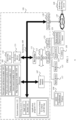
- FIG. 1 is a schematic structural diagram of a computer system (or an in-vehicle system) applicable to an embodiment of this application.
- the computer system may be located on a vehicle.
- the computer system may include an in-vehicle device 101, a device/component/network directly or indirectly connected to the in-vehicle device 101, and the like.
- the in-vehicle device 101 includes a processor 103, and the processor 103 is coupled to a system bus 105.
- the processor 103 may be one or more processors, and each processor may include one or more processor cores.
- a display adapter 107 may drive a display 109, and the display 109 is coupled to the system bus 105.
- the system bus 105 is coupled to an input/output (I/O) bus 113 through a bus bridge 111.
- An I/O interface 115 is coupled to the I/O bus.
- the I/O interface 115 communicates with a plurality of I/O devices, for example, an input device 117 (for example, a keyboard, a mouse, and a touchscreen), a media tray 121 (for example, a compact disc read-only memory (CD-ROM), and a multimedia interface), a transceiver 123 (which may send and/or receive a radio communication signal), a universal serial bus (USB) port 125, and a camera 155 (which may capture static and dynamic digital video images).
- I/O input/output
- USB universal serial bus
- the processor 103 may be any conventional processor, including a reduced instruction set computing (RISC) processor, a complex instruction set computing (CISC) processor, or a combination thereof.
- the processor may be a dedicated apparatus such as an application specific integrated circuit (ASIC).
- the processor 103 may be a neural processing unit or a combination of a neural processing unit and the foregoing conventional processor.
- the processor 103 may include a main controller (which may also be referred to as a central controller) and an advanced driver assistance system controller.
- the main controller is a control center of the computer system.
- the ADAS controller is configured to control a self-driving route, an assisted self-driving route, or the like.
- the display 109 may be any one or more HMI devices installed on the vehicle.
- the display 109 may include: a head up display (HUD), a dashboard, and a display dedicated for a passenger.
- HUD head up display
- dashboard dashboard
- display dedicated for a passenger a display dedicated for a passenger.
- the in-vehicle device 101 may be located far away from a self-driving vehicle, and may wirelessly communicate with the self-driving vehicle.
- some of the processes described in this specification are performed by a processor disposed in a self-driving vehicle, and others are performed by a remote processor.
- the in-vehicle device 101 may communicate with a software deploying server 149 through a network interface 129.
- the network interface 129 is a hardware network interface such as a network interface card.
- a network 127 may be an external network such as the internet, or an internal network such as the Ethernet or a virtual private network (VPN).
- the network 127 may alternatively be a wireless network such as a Wi-Fi network or a cellular network.
- a hard disk drive interface is coupled to the system bus 105.
- the hardware driver interface is connected to a hard disk driver.
- a system memory 135 is coupled to the system bus 105. Data running in the system memory 135 may include an operating system 137 and an application program 143 of the in-vehicle device 101.
- the operating system includes a shell 139 and a kernel 141.
- the shell 139 is an interface between a user and the kernel of the operating system.
- the shell is an outermost layer of the operating system.
- the shell manages interaction between the user and the operating system: waiting for an input of the user, explaining the input of the user to the operating system, and processing various output results of the operating system.
- the kernel 141 includes components of the operating system that are configured to manage a memory, a file, a peripheral, and system resources.
- the kernel 141 directly interacts with hardware.
- the kernel of the operating system usually runs processes, and provides communication between processes, CPU time slice management, interrupt management, memory management, I/O management, and the like.
- a sensor 153 is associated with the in-vehicle device 101.
- the sensor 153 is configured to detect an ambient environment of the in-vehicle device 101.
- the sensor 153 may detect an animal, a vehicle, an obstacle, and a crosswalk.
- the sensor may detect ambient environments of the foregoing objects such as the animal, the vehicle, the obstacle, and the crosswalk.
- the sensor may detect the ambient environment of the animal, such as another animal, a weather condition, and brightness of the ambient environment of the animal.
- the sensor may be a camera, an infrared sensor, a chemical detector, a microphone, or the like.
- the senor 153 may include a speed sensor, configured to measure speed information (such as a speed and an acceleration) of the vehicle (that is, the vehicle in which the computer system shown in FIG. 1 is located), and an angle sensor, configured to measure direction information of the vehicle, a relative angle between the vehicle and an object around the vehicle, and the like.
- speed information such as a speed and an acceleration
- angle sensor configured to measure direction information of the vehicle, a relative angle between the vehicle and an object around the vehicle, and the like.
- the sensor 153 may include a laser radar sensor, configured to detect a reflected signal of a laser signal sent by a laser radar, to obtain a laser point cloud.
- the laser radar may be installed at top of the vehicle to send a laser signal.
- the point cloud described in the embodiments of this application may be a laser point cloud.
- the processor 103 includes:
- All the foregoing modules may be implemented by using software and/or hardware.
- any one or more of the modules may be disposed independently, or may be integrated together. This is not specifically limited in the embodiments of this application. In an example, any one or more of these modules may be used as a logical function module in the main controller or the ADAS controller.
- FIG. 1 is merely an example, and does not constitute a limitation on a computer system to which the embodiments of this application are applicable.
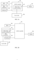
- FIG. 2A and FIG. 2B are schematic structural diagrams of other computer systems according to an embodiment of this application.
- Each of the computer systems shown in FIG. 2A and FIG. 2B may include: an ADAS controller 201, an HUD 202 connected to the ADAS controller 201, a main controller 203 (that is, a central controller), a dashboard 204, and a display 205 dedicated for a passenger.
- a main controller 203 that is, a central controller
- dashboard 204 a dashboard 204
- display 205 dedicated for a passenger.
- a point cloud control module 207 is located in the ADAS controller 201.
- a point cloud control module 207 is located in the main controller 203.
- the point cloud control module 207 may be a software program, and is configured to implement another step other than a display step in a point cloud display method provided in the embodiments of this application.
- the computer system further includes a laser radar 206, and the laser radar 206 may be connected to the point cloud control module 207.
- the objects include objects on a road and objects outside a road.
- the objects on a road include people, a vehicle, a traffic light, a traffic sign (for example, a speed limit sign), a traffic sign post, and a foreign object.
- the foreign object is to an object that should not appear on the road, such as a carton and a tire left on the road.
- the objects outside a road include buildings and trees on both sides of the road, and a median strip in the middle of the road.
- the target object is an object that needs to be identified by an in-vehicle device (or an in-vehicle system).
- the target object may be predefined, or indicated by a user.
- the target object includes a target obstacle on a road and some or all objects outside the road.
- all objects on the road except the vehicle may be considered as obstacles.
- the target obstacle may be an obstacle of a specific type.
- the target obstacle may be people or a vehicle.
- the target obstacle may be an obstacle whose speed is greater than or equal to a preset threshold (for example, 0).
- a correlation between a target object and the vehicle exceeds a threshold.
- the correlation is determined based on at least one of the following factors: a distance between the target object and the vehicle, a location of the target object, information indicated by the target object, or a speed of the target object.
- a type of information used to represent the location of the target object is not limited in the embodiments of this application.
- the location of the target object may be that the target object is on a road or outside a road, or the target object is located in a direction of the vehicle.
- the information indicated by the target object may be understood as whether the target object indicates predefined information.
- the correlation may be determined based on whether the target object indicates traffic information.
- a method for determining the correlation between the target object and the vehicle based on the foregoing factors is not limited in the embodiments of this application.
- a target object closer to the vehicle has a higher correlation with the vehicle.
- a correlation between the vehicle and a target object on a road on which the vehicle is located is higher than a correlation between the vehicle and a target object outside the road on which the vehicle is located.
- a correlation between the vehicle and a target object in front of the vehicle is higher than a correlation between the vehicle and a target object right behind the vehicle.
- a correlation between the vehicle and a target object at a relatively high speed is higher than a correlation between the vehicle and a target object at a relatively low speed.
- a surrounding area of a vehicle is a specific scope around the vehicle.
- the surrounding area of the vehicle may be determined based on an installation location and a scanning radius of the laser radar.
- the surrounding area of the vehicle may be a circular area centered on the laser radar with a radius of the scanning radius of the laser radar.
- an obtained surrounding area of the vehicle may not be a circle due to factors such as existence of an obstacle (for example, a wall) in an environment in which the vehicle is located.
- an example in which the surrounding area of the vehicle is a circle is used for description.
- the point cloud cropping means processing a point cloud to obtain a part of the point cloud.
- a point cloud cropping process may include: first determining a cropping boundary, then cropping the point cloud based on the cropping boundary, and then using an image within or beyond the cropping boundary as a cropping result.
- Vehicle scenario that is, a scenario in which a vehicle is located
- a method for distinguishing a scenario in which a vehicle is located is not limited in the embodiments of this application.
- Manner 1 The scenario in which the vehicle is located is distinguished based on a driving status of the vehicle.
- the scenario in which the vehicle is located may be classified into a parking scenario and a non-parking scenario depending on whether the vehicle is being parked.
- the scenario in which the vehicle is located may be classified into a reverse scenario and a non-reverse scenario depending on whether the vehicle is being reversed.
- the scenario in which the vehicle is located may be classified into a turning scenario and a go-straight scenario depending on whether the vehicle is going straight.
- the point cloud control module may obtain, from the planning control module, whether the vehicle is currently in the parking scenario, obtain, from the gear control module, whether the vehicle is in the reverse scenario, and obtain, from an angle sensor, whether the vehicle is currently in the turning scenario and the go-straight scenario.
- the point cloud control module may send a request message to the planning control module, and the planning control module sends, to the point cloud control module based on the request message, a response message indicating whether the vehicle is currently in the parking scenario.
- the point cloud control module may send a request message to the gear control module, and the gear control module sends, to the point cloud control module based on the request message, a response message indicating whether the vehicle is currently in the reverse scenario.
- the planning control module may send, to the point cloud control module, indication information used to indicate that the vehicle is currently in the parking scenario.
- the gear control module may send, to the point cloud control module, indication information used to indicate that the vehicle is currently in the reverse scenario.
- the angle sensor may periodically (or in real time) send current direction information of the vehicle to the point cloud control module, and the point cloud control module may determine, based on the direction information, whether the vehicle is currently in the turning scenario and the go-straight scenario.
- Manner 2 The scenario in which the vehicle is located is distinguished based on a weather condition of an environment in which the vehicle is located.
- the scenario in which the vehicle is located may include a sunny day scenario, a rain scenario, a cloudy scenario, a hail scenario, and a haze scenario.
- the foregoing scenarios may be further divided at a finer granularity.
- the rain scenario may be further divided into a heavy rain scenario, a moderate rain scenario, and a light rain scenario.
- the point cloud control module may obtain, from the perception and fusion control module, the weather condition of the environment in which the vehicle is located, to determine, based on the weather condition, the scenario in which the vehicle is currently located.
- the perception and fusion control module may periodically send or may be triggered to send the weather condition of the environment in which the vehicle is located to the point cloud control module.
- Manner 3 The scenario in which the vehicle is located is distinguished based on a light condition of an environment in which the vehicle is located.
- the scenario in which the vehicle is located may include a daytime scenario and a nighttime scenario.
- the point cloud control module may obtain, from the perception and fusion control module, whether the current scenario of the vehicle is the daytime scenario or the nighttime scenario.
- Manner 4 The scenario in which the vehicle is located is distinguished based on a road condition of a road on which the vehicle is located.
- the scenario in which the vehicle is located is distinguished based on a road width of the road on which the vehicle is located.
- the scenario in which the vehicle is located may include a wide-road scenario and a narrow-road scenario.
- the wide-road scenario and the narrow-road scenario herein are relative.
- the width of the road on which the vehicle is located is greater than or equal to a threshold, it may be considered that the vehicle is currently in the wide-road scenario.
- the width of the road on which the vehicle is located is less than the threshold, it may be considered that the vehicle is currently in the narrow-road scenario.
- the scenario in which the vehicle is located is distinguished based on whether the road on which the vehicle is located is an intersection. Based on this, for example, the scenario in which the vehicle is located may include an intersection scenario and a non-intersection scenario.
- information obtained by the point cloud control module from another device/module/component may be information used to obtain the current scenario of the vehicle, but a result is not limited to the current scenario.
- the point cloud control module may obtain, from the perception and fusion module, the light condition of the environment in which the vehicle is located, to determine, based on the light condition, whether the current scenario is the daytime scenario or the nighttime scenario. Other examples are not enumerated.
- the another device/module/component can directly obtain the current scenario of the vehicle, the another device/module/component may exchange information with the point cloud control module, so that the point cloud control module obtains the current scenario of the vehicle.
- the scenario in which the vehicle is located when the scenario in which the vehicle is located is distinguished based on whether the vehicle is being reversed and the road width of the road on which the vehicle is located, the scenario in which the vehicle is located may include: a wide-road reverse scenario, a wide-road non-reverse scenario, a narrow-road reverse scenario, and a narrow-road non-reverse scenario. Other examples are not enumerated.
- the word such as “example” or “for example” is used to give an example, an illustration, or a description. Any embodiment or design scheme described as the word “example” or “for example” in the embodiments of this application should not be explained as being more preferred or having more advantages than another embodiment or design scheme. Exactly, use of the word “example” or “for example” or the like is intended to present a related concept in a specific manner.
- At least one means one or more.
- a plurality refers to two or more than two.
- a and/or B may represent the following three cases: Only A exists, both A and B exist, and only B exists.
- the character "/" in this specification usually indicates an "or" relationship between the associated objects.
- FIG. 3 is a schematic flowchart of an image processing method according to an embodiment of this application. The method shown in FIG. 3 may include the following steps.
- a laser radar sensor sends an original point cloud sequence to a point cloud control module.
- the original point cloud sequence is a point cloud sequence formed by point clouds collected by the laser radar sensor.
- a collection time of a point cloud in the front of the original point cloud sequence is earlier than a collection time of a point cloud in the rear of the original point cloud sequence.
- a collection time of a point cloud is a time at which the laser radar sensor collects the point cloud.
- the original point cloud sequence in S 101 may be a point cloud sequence formed by any frames of point clouds sent by the laser radar sensor to the point cloud control module.
- the laser radar sensor may periodically send collected point clouds to the point cloud control module.
- a sequence formed by point clouds sent in each period may be used as an original point cloud sequence.
- Each frame of point cloud collected by the laser radar sensor is a point cloud used to describe an object in a surrounding area of a vehicle in which the point cloud control module is located. It may be understood that, as the vehicle moves or an object in the surrounding area of the vehicle changes, point clouds of different frames collected by the laser radar sensor may be different.
- the point cloud control module obtains a current scenario of the vehicle (referred to as a host vehicle below) in which the point cloud control module is located.
- the current scenario of the host vehicle may be any scenario described in the foregoing examples of distinguishing a scenario in which a vehicle is located.
- the current scenario includes a nighttime scenario or a rain scenario.
- the current scenario of the host vehicle may be a plurality of scenarios distinguished according to a plurality of standards.
- the current scenario includes a nighttime scenario and a rain scenario.
- the point cloud control module determines a sampling frequency based on the current scenario of the host vehicle.
- the sampling frequency is a sampling frequency used when sampling is performed on the original point cloud sequence.
- the point cloud control module may predefine a correspondence between each scenario in which the vehicle is located and a sampling frequency corresponding to the scenario.
- the scenario in which the vehicle is located includes two scenarios: a sunny day scenario and a rain scenario.
- the point cloud control module may predefine that a sampling frequency corresponding to the sunny day scenario is f1, and a sampling frequency corresponding to the rain scenario is f2.
- Each scenario corresponds to one sampling frequency.
- Different scenarios distinguished according to a same standard correspond to different sampling frequencies, and different scenarios distinguished according to different standards may correspond to a same sampling frequency or different sampling frequencies.
- sampling frequencies corresponding to the sun day scenario and the rain scenario are different (that is, f1 and f2 are unequal).
- the sampling frequency in the rain scenario can be the same as or different from that in the nighttime scenario.
- the sampling frequency of the current scenario may be a largest sampling frequency in sampling frequencies corresponding to the plurality of scenarios. For example, if the current scenario includes the nighttime scenario and the rain scenario, and the nighttime scenario and the rain scenario correspond to sampling frequencies 5 Hz and 10 Hz respectively, the sampling frequency of the current scenario may be 10 Hz.
- the sampling frequency of the current scenario may be a sampling frequency obtained after an operation is performed, according to a preset algorithm, on sampling frequencies corresponding to the plurality of scenarios.
- a specific implementation of the preset algorithm is not limited in this embodiment of this application.
- the sampling frequency of the current scenario may be a sampling frequency obtained after an operation is performed, according to the preset algorithm, on the sampling frequency 5 Hz corresponding to the nighttime scenario and the sampling frequency 10 Hz corresponding to the rain scenario.
- a sampling frequency corresponding to a special scenario (that is, a scenario in which a road condition is relatively complex) is greater than a sampling frequency corresponding to a common scenario (that is, a scenario in which a road condition is less complex).
- a sampling frequency corresponding to a parking scenario is greater than a sampling frequency corresponding to a non-parking scenario.
- a sampling frequency corresponding to a reverse scenario is greater than a sampling frequency corresponding to a non-reverse scenario.
- a sampling frequency corresponding to a turning scenario is greater than a sampling frequency corresponding to a go-straight scenario.
- the sampling frequency corresponding to the rain scenario is greater than the sampling frequency corresponding to the sunny day scenario.
- the sampling frequency corresponding to the nighttime scenario is greater than a sampling frequency corresponding to a daytime scenario.
- a sampling frequency corresponding to a narrow-road scenario is greater than a sampling frequency corresponding to a wide-road scenario.
- a sampling frequency corresponding to an intersection scenario is greater than a sampling frequency corresponding to a non-intersection scenario.
- sampling frequencies corresponding to at least two (for example, all) of the parking scenario, the reverse scenario, the turning scenario, the rain scenario, the nighttime scenario, the narrow-road scenario, and the intersection scenario are the same, and the sampling frequency is greater than a sampling frequency corresponding to another scenario.
- a sampling frequency corresponding to a common scenario that is, another scenario other than the intersection scenario and the nighttime scenario
- the sampling frequency corresponding to the intersection scenario is 5 Hz
- the sampling frequency corresponding to the nighttime scenario is 18 Hz.
- identification accuracy of an in-vehicle device for a target object is different. For example, when the vehicle is in the daytime scenario, identification accuracy of the in-vehicle device for the target object is lower compared with that when the vehicle is in the nighttime scenario.
- the sampling frequency is determined based on the current scenario of the vehicle. This helps meet requirements on identification accuracy for the target object in different scenarios, to improve user experience.
- the point cloud control module performs sampling on the original point cloud sequence based on the determined sampling frequency, to obtain a first point cloud sequence.
- the performing sampling on the original point cloud sequence to obtain a first point cloud sequence may be understood as: selecting some point clouds in the original point cloud sequence, and forming the first point cloud sequence by using the selected point clouds in a chronological order of sampling times.
- a method for performing sampling is not limited in this embodiment of this application. For example, uniform sampling may be performed. For example, one frame of point cloud is selected from the original point cloud sequence every n frames, where n is an integer greater than or equal to 1.
- the sampling frequency is 10 Hz
- one frame of point cloud is selected from the original point cloud sequence every six frames
- the sampling frequency is 20 Hz
- one frame of point cloud is selected from the original point cloud sequence every three frames.
- the sampling frequency is 10 Hz
- the 1 st , 7 th , 13 th , and 20 th , ..., frames of point clouds may be selected from the original point cloud sequence to form the first point cloud sequence
- the sampling frequency is 20 Hz
- the 1 st , 4 th , 7 th , 10 th , 13 th , 16 th , and 19 th , ..., frames of point clouds may be selected from the original point cloud sequence to form the first point cloud sequence.
- FIG. 4 is a schematic diagram of comparison between the original point cloud sequence and the first point cloud sequence.
- the in-vehicle device For each frame of point cloud in the first point cloud sequence, the in-vehicle device performs the following steps S105 to S108.
- S102 to S104 are optional steps. Sampling is performed on the original point cloud sequence, so that S105 to S108 are performed on a point cloud in the first point cloud sequence obtained through sampling, instead of each frame of point cloud in the original point cloud sequence. This helps reduce computations of point cloud processing. Further, the sampling frequency is determined based on the current scenario of the host vehicle, rather than a same sampling frequency is used in all scenarios. This helps meet requirements on identification accuracy for the target object in different scenarios, to help balance the computations of point cloud processing and the requirements on identification accuracy for the target object, and improving an overall effect of point cloud processing.
- the point cloud control module determines, from a first point cloud in the first point cloud sequence, points used to describe the target object.
- the first point cloud may be any frame of point cloud in the first point cloud sequence.
- the point cloud control module crops the first point cloud to obtain the points used to describe the target object (for example, each target object) in the first point cloud.
- the method may further include: presenting a setting request, where the setting request is used to prompt a driver of the host vehicle to set a type of an object included in the target object, and then, determining, based on a received setting response, the type of the object included in the target object.
- a presentation manner of the setting request is not limited in this embodiment of this application.
- the setting request may be presented by a display by using text or a picture, presented by a speaker by using audio, or a combination of the two.
- the type of an object may include people, a bicycle, an electric bicycle, a car, a truck, a traffic sign pole, and the like.
- a user for example, the driver
- types of some or all target objects may be predefined. In some other implementations, types of some target objects are predefined, and types of the other target objects may be set by a user.
- S 105 A specific implementation of S 105 is described below based on a relationship between the target object and a road.
- the point cloud control module crops the first point cloud based on a location of a road marking on a map of the surrounding area of the host vehicle, to obtain points used to describe the object outside the road.
- the road marking may include at least one of a road line, a lane line, and a stop line.
- a location of the road marking may be an absolute location or a relative location.
- the map may be prestored in a memory of the in-vehicle device, or may be a map application developed by a third party.
- the map includes coordinate information and sizes of various road markings (for example, a road line, a lane line, and a stop line).
- the map described herein is a general map, for example, a map including a city or a map including all parts of a country.
- a map management module may be configured to manage a map stored in the memory.
- the point cloud control module may send a request message to the map management module, where the request message is used to request to obtain a map of a specific surrounding area of the host vehicle.
- the request message may include location information of the host vehicle, and the location information of the host vehicle may be obtained by the point cloud control module from a module/component/device configured to position the host vehicle.
- the map management module After receiving the request message, the map management module sends the map of the specific surrounding area of the host vehicle to the point cloud control module.
- a size of the surrounding area of the host vehicle that is determined by the map management module may be the same as or different from a size of a surrounding area of the host vehicle that is determined by the point cloud control module.
- the point cloud control module crops the first point cloud based on a location of a road marking on a map of a surrounding area of the host vehicle, to obtain points used to describe the object other than the road may include:
- FIG. 5a to FIG. 5c are a schematic diagram of a process of obtaining the points used to describe the object outside the road.
- FIG. 5a represents the first point cloud.
- FIG. 5a shows only the host vehicle and the scanning range of the laser radar on the host vehicle.
- FIG. 5b is the map that is of the surrounding area of the host vehicle and that is obtained by the point cloud control module. The map includes a road marking.
- an original lane is a lane in which the host vehicle is located
- an opposite lane is a lane in which a vehicle whose driving direction is opposite to that of the host vehicle is located.
- the point cloud control module superimposes FIG. 5a on FIG. 5b to obtain FIG. 5c .
- FIG. 5c Locations of the host vehicle in FIG. 5a, FIG. 5b, and FIG. 5c are the same. Boundaries of dash areas in FIG. 5c are cropping boundaries, and the dash areas in FIG. 5c are the points used to describe the object outside the road. FIG. 5c includes three dash areas in total. Dash areas on a leftmost side and a rightmost side may be considered as trees, buildings, and the like outside the road, and a dash area in the middle may be considered as a median strip and the like in the middle of the road.
- the point cloud control module crops the first point cloud based on a location and a size of the target obstacle on the road, to obtain points that are in the first point cloud and that are used to describe the target obstacle.
- the following describes a specific implementation in which the point cloud control module determines the target obstacle in the first point cloud.
- Manner 1 The point cloud control module determines the target obstacle based on location information of the object.
- the point cloud control module obtains location information of one or more candidate obstacles, selects a candidate obstacle on the road from the one or more candidate obstacles based on the location information of the one or more candidate obstacles, and uses the selected candidate obstacle as the target obstacle.
- the candidate obstacle is an obstacle that is in the surrounding area of the host vehicle, that is obtained by the point cloud control module from the perception and fusion control module, and that is identified by the perception and fusion control module.
- This embodiment of this application imposes no limitation on a method for identifying an obstacle in the surrounding area of the host vehicle by the perception and fusion control module and the like, a method for obtaining information about the identified obstacle, and a method for exchanging information with the point cloud control module, to enable the point cloud control module to obtain the information.
- the perception and fusion control module may periodically send or may be triggered to send, to the point cloud control module, information (such as location information, speed information, length and width information, and classification information) about an obstacle that is in the surrounding area of the host vehicle and that is identified by the point cloud control module.
- information such as location information, speed information, length and width information, and classification information
- the location information of the obstacle may be location information used to represent an absolute location or a relative location (for example, a location relative to the host vehicle) of the obstacle.
- the absolute location of the obstacle may be represented by a longitude and a latitude of a location of the obstacle or coordinate values of the location in a world coordinate system.
- the location of the obstacle relative to the host vehicle may be represented by coordinate values of the obstacle in a vehicle coordinate system.
- the length and width information of the obstacle is a length and a width of a rectangular area occupied by the obstacle on the road (that is, a two-dimensional plane).
- the rectangular area may be a rectangular area including "a projection area of the obstacle on a two-dimensional plane on which the road is located".
- the classification information of the obstacle is information used to represent a type of the obstacle.
- the type of the obstacle may include people, a bicycle, an electric bicycle, a car, a truck, a traffic sign pole, or the like.
- Manner 1 is a technical solution proposed considering that "for a same vehicle, a size of a surrounding area of the vehicle that is determined by the perception and fusion control module may be the same as or different from a size of a surrounding area of the vehicle that is determined by the point cloud control module; and therefore, a candidate obstacle identified by the perception and fusion control module may be on or outside a road in the surrounding area of the vehicle that is determined by the point cloud control module.”
- the point cloud control module may directly use the obtained candidate obstacle as the target obstacle.
- the point cloud control module obtains the location information of the candidate obstacle from the perception and fusion control module, obtain location information of the road on which the host vehicle is located from the map of the surrounding area of the vehicle, and then, determine, with reference to the location information of the road and the location information of the candidate obstacle, whether the candidate obstacle is on the road.
- Manner 2 The point cloud control module determines the target obstacle based on speed information of the object.
- the point cloud control module obtains speed information of one or more candidate obstacles on the road, and selects, from the one or more candidate obstacles based on the speed information of the one or more candidate obstacles, a candidate obstacle whose speed is greater than or equal to a preset threshold (for example, 0), and uses the selected candidate obstacle as the target obstacle.
- a preset threshold for example, 0
- the speed herein may be an absolute speed. That is, the target obstacle selected in Manner 2 is a dynamic obstacle, that is, an obstacle whose location can be moved, such as people or a vehicle. For descriptions of the candidate obstacle, refer to Manner 1.
- the candidate obstacles determined by the perception and fusion control module include a static obstacle (for example, a traffic light or a traffic sign pole) and a dynamic obstacle (for example, people or a vehicle); in the field of autonomous driving or assisted autonomous driving technologies, generally, the dynamic obstacle attracts more attention than the static obstacle, or an obstacle with a higher speed attracts more attention than an obstacle with a lower speed.”
- a static obstacle for example, a traffic light or a traffic sign pole
- a dynamic obstacle for example, people or a vehicle
- Manner 1 and Manner 2 may be combined to obtain a new implementation.
- this embodiment of this application supports the technical solution in which the point cloud control module uses, as the target obstacle, a candidate obstacle that is on the road and whose speed is greater than or equal to the preset threshold.
- the technical solution may be described as follows: The point cloud control module filters out, from the obtained candidate obstacles, a static obstacle or an obstacle with a relatively low speed that is located beyond an edge of the road.
- the following describes a specific implementation in which the point cloud control module obtains the location and the size of the target obstacle on the road.
- the location information of the target obstacle is obtained by the point cloud control module from the perception and fusion control module.
- the size of the target obstacle may be a length, a width, and a height of a cuboid (that is, a three-dimensional detection frame of the target obstacle) that includes the target obstacle.
- the point cloud control module obtains the length and the width of the target obstacle from the perception and fusion control module.
- the point cloud control module may obtain the height of the target obstacle based on classification information of the target obstacle. For example, a height of an obstacle of each type is predefined. For example, a height of people is 2 m, a height of a bicycle is 2 m, a height of an electric bicycle is 2 m, a height of a car is 3 m, a height of a truck is 4 m, and a height of a traffic sign pole is 5 m.
- the point cloud control module may obtain the classification information of the target obstacle from another device/module/component (for example, the perception and fusion control module). The three-dimensional detection frame of the target obstacle obtained in this manner is closer to the target obstacle. Therefore, accuracy is high.
- the length, the width, and the height of the target obstacle each may be of a predefined size. That is, a size of each target obstacle is represented according to a predefined point cloud model.
- the predefined point cloud model is a three-dimensional detection frame whose length, width, and height each are of a fixed size. This manner is easy to implement.
- the point cloud control module After obtaining location information and a size of any target obstacle, the point cloud control module determines a location and a size of a three-dimensional detection frame (that is, a three-dimensional region that includes the target obstacle) of the target obstacle, to crop the first point cloud based on the three-dimensional detection frame, so as to obtain points that are in the first point cloud and that are used to describe the target obstacle. That is, points in the three-dimensional detection frame in the first point cloud are used as points used to describe the target obstacle.
- the point cloud control module obtains points that are in the first point cloud and that are used to describe each target obstacle.
- FIG. 6a and FIG. 6b are a schematic diagram of a process of obtaining the points used to describe the target obstacle on the road.
- FIG. 6a represents the first point cloud.
- the point cloud control module may obtain, based on FIG. 6a and the obtained location and size of the three-dimensional detection frame of the target obstacle, the location and the size of the target obstacle on the road in FIG. 6a .
- dash areas in FIG. 6b each dash area in FIG. 6b represents one target obstacle.
- the point cloud control module generates a second point cloud based on the points used to describe the target object. For example, locations of the points used to describe the target object in the first point cloud are the same as locations of the points in the second point cloud.
- FIG. 7a to FIG. 7c it is assumed that a sub-point cloud used to describe the objects outside the road is shown in dash areas in FIG. 7a (that is, FIG. 5c ), and a sub-point cloud used to describe the target obstacles on the road is shown in dash areas in FIG. 7b (that is, FIG. 6b ).
- the dash areas in FIG. 7a and the dash areas in FIG. 7b may be combined, to obtain dash areas (that is, the second point cloud) in FIG. 7c .
- S105 may include: The point cloud control module crops the first point cloud based on feature information of a first-type target object, to obtain a first sub-point cloud used to describe the first-type target object, where the target objects include a first-type target object and a second-type target object.
- the point cloud control module crops the first point cloud based on feature information of the second-type target object, to obtain a second sub-point cloud used to describe the second-type target object.
- S106 may include: The point cloud control module generates the second point cloud based on the first sub-point cloud and the second sub-point cloud.
- the point cloud when there are a plurality of types of target objects, the point cloud may be cropped based on feature information of each type of target object, and the second point cloud is generated based on cropping results (that is, sub-point clouds).
- the feature information of the object described above is merely an example, and does not constitute a limitation on feature information applicable to this embodiment of this application. It may be understood that, referring to FIG. 7a to FIG. 7c , compared with the points in the first point cloud, the second point cloud does not include points outside the dash areas in FIG. 7c . These points are specifically ground reflection points generated by the laser radar in a scanning process, and the like. In this way, computational complexity and display complexity of the point cloud can be reduced.
- the target object can be set, during actual implementation, the target object may include more or fewer objects than those described in this embodiment of this application.
- the point cloud control module uses, as the second point cloud, the points used to describe the target object. Compared with directly displaying the first point cloud, this helps reduce a quantity of points in a displayed point cloud, to lower a requirement on hardware performance of a display device. In addition, this is easy to implement.
- Sparsification on a point cloud is a process in which to reduce computational complexity or display complexity of the point cloud, sampling is performed on points in the point cloud, to form a new point cloud.
- Profiles of a same object in point clouds before and after sparsification are consistent or basically consistent.
- FIG. 8a and FIG. 8b are schematic diagrams of points in a rectangle in point clouds before and after sparsification.
- FIG. 8a represents the rectangle before sparsification
- FIG. 8b represents the rectangle after sparsification.
- a sampling method in a sparsification process is not limited in this embodiment of this application.
- a sparsification multiple refers to a ratio of a quantity of points that are included in an area before sparsification to a quantity of points that are included in the area after sparsification. For a same area, a larger sparsification multiple indicates a larger sparsity, that is, a smaller quantity of points obtained after sparsification.
- this embodiment of this application supports a technical solution in which points farther away from the vehicle are less sparse.
- the optional technical solution helps describe, by using a relatively large quantity of points, an object that is relatively far away from the vehicle. In this way, points that are relatively far away from the vehicle are relatively clear while a total quantity of points in the point cloud is reduced, to help improve user experience and improve driving safety.
- the point cloud control module sends the second point cloud to a display.
- the point cloud control module may directly or indirectly send the second point cloud to the display.
- the display may be an HUD or a dashboard.
- the display may directly display the second point cloud.
- the display may superimpose the second point cloud on information (for example, information such as a road marking on the map) about another object in the surrounding area of the vehicle, to obtain a new point cloud, and display the new point cloud.
- FIG. 9 shows a new point cloud obtained after the second point cloud is combined with the information such as the road marking on the map.
- the display may further display more information used to indicate the surrounding area of the vehicle, to further improve user experience.
- the points used to describe the target object are determined in the first point cloud, the second point cloud is generated based on the points used to describe the target object, and the second point cloud is displayed.
- the second point cloud replaces the first point cloud for display. This helps reduce a data amount of the point cloud that needs to be displayed.
- the first point cloud may be a laser point cloud
- this method helps reduce a data amount of the laser point cloud, to help lower the requirement on hardware performance of the display device. In this way, a point cloud that can be displayed on an HMI device installed on the vehicle can be obtained.
- the in-vehicle may be divided into function modules based on the foregoing method examples.
- each function module may be obtained through division based on each function, or two or more functions may be integrated into one processing module.
- the integrated module may be implemented in a form of hardware, or may be implemented in a form of a software function module. It should be noted that, in the embodiments of this application, division into the modules is an example, and is merely logical function division. During actual implementation, another division manner may be used.
- FIG. 10 is a schematic structural diagram of a point cloud display apparatus 90 according to an embodiment of this application.
- the point cloud display apparatus 90 includes a processor 901 and a display 902.
- the processor 901 and the display 902 may be separate components, or may be integrated together.
- the processor 901 and the display 902 may be connected in a wired or wireless manner.
- the processor 901 and the display 902 may be connected through a cable, or may be connected through Wi-Fi or Bluetooth.
- the processor 901 is configured to perform the foregoing steps performed by the point cloud control module.
- the display 902 is configured to perform the foregoing steps performed by the display.
- the processor 901 is configured to determine, from a first point cloud, points used to describe a target object, where the first point cloud is a point cloud used to describe a surrounding area of a vehicle in which the in-vehicle system is located, and the target object is an object that needs to be identified by the in-vehicle system; and generate a second point cloud based on the points used to describe the target object.
- the display 902 is configured to display the second point cloud.
- the processor 901 is configured to perform S 105 and S 106.
- the display 902 is configured to perform S 108.
- a correlation between the target object and the vehicle exceeds a threshold.
- the correlation is determined based on at least one of the following factors: a distance between the target object and the vehicle, a location of the target object, information indicated by the target object, or a speed of the target object.
- the apparatus 90 further includes an output module 903, configured to present a setting request, where the setting request is used to prompt a user (for example, a driver of the vehicle) to set a type of an object included in the target object.
- the processor 901 is further configured to determine, based on a received setting response, the type of the object included in the target object.
- the output module 903 and the display 902 may be the same or different. For example, if the presentation setting request is presented by a display, the output module 903 and the display 902 may be a same display, or certainly may be different displays. For another example, if the presentation setting request is presented by a speaker (that is, presented through audio), the output module 903 is different from the display 902.
- the processor 901 is specifically configured to generate the second point cloud through sparsification on a third point cloud, where the third point cloud is a set of points used to describe the target object.
- the third point cloud includes a first area and a second area.
- a distance between the vehicle and an object described by points in the first area is greater than a distance between the vehicle and an object described by points in the second area.
- the processor 901 is specifically configured to perform sparsification on the points in the first area by using a first sparsification multiple, and perform sparsification on the points in the second area by using a second sparsification multiple, where the first sparsification multiple is less than the second sparsification multiple.
- the processor 901 is further configured to perform sampling on an original point cloud sequence obtained by the in-vehicle system, to obtain a first point cloud sequence, where the first point cloud is any frame of point cloud in the first point cloud sequence.
- the processor 901 is specifically configured to determine a sampling frequency based on a current scenario of the vehicle in which the in-vehicle system is located, and perform sampling on the original point cloud sequence based on the sampling frequency, to obtain the first point cloud sequence.
- the processor 901 may be configured to perform S 103 and S104.
- the processor 901 is specifically configured to: when the target object includes an object outside a road, crop the first point cloud based on a location of a road marking on a map of the surrounding area, to obtain points used to describe the object outside the road.
- the processor 901 is specifically configured to: when the target object includes a target obstacle on a road, determine the target obstacle based on location information or speed information of the object, and crop the first point cloud based on a location and a size of the target obstacle, to obtain points used to describe the target obstacle.
- the processor 901 is specifically configured to obtain location information of one or more candidate obstacles, select a candidate obstacle on the road from the one or more candidate obstacles based on the location information of the one or more candidate obstacles, and use the selected candidate obstacle as the target obstacle.
- the processor 901 is specifically configured to crop the first point cloud based on feature information of a first-type target object, to obtain a first sub-point cloud used to describe the first-type target object, where the target object includes the first-type target object and a second-type target object; and crop the first point cloud based on feature information of the second-type target object, to obtain a second sub-point cloud used to describe the second-type target object.
- the generating a second point cloud based on the points used to describe the target object includes: generating the second point cloud based on the first sub-point cloud and the second sub-point cloud.
- FIG. 11 is a schematic structural diagram of a point cloud display apparatus 100 according to an embodiment of this application.
- the apparatus 100 is configured to perform the foregoing point cloud display method.
- the apparatus is applied to an in-vehicle system.
- the apparatus 100 includes a determining unit 1001, a generation unit 1002, and a display unit 1003.
- the determining unit 1001 is configured to determine, from a first point cloud, points used to describe a target object, where the first point cloud is a point cloud used to describe a surrounding area of a vehicle in which the in-vehicle system is located.
- the generation unit 1002 is configured to generate a second point cloud based on the points used to describe the target object, where the target object is an object that needs to be identified by the in-vehicle system.
- the display unit 1003 is configured to display the second point cloud.
- the determining unit 1001 is configured to perform S105
- the generation unit S106 is configured to perform S106
- the display unit 1003 is configured to perform S108
- a correlation between the target object and the vehicle exceeds a threshold.
- the correlation is determined based on at least one of the following factors: a distance between the target object and the vehicle, a location of the target object, information indicated by the target object, or a speed of the target object.
- the apparatus 100 further includes an output unit 1004, configured to present a setting request, where the setting request is used to prompt a user (for example, a driver of the vehicle) to set a type of an object included in the target object.
- the determining unit 1001 is further configured to determine, based on a received setting response, the type of the object included in the target object.
- the generation unit 1002 is specifically configured to generate the second point cloud through sparsification on a third point cloud, where the third point cloud is a set of points used to describe the target object.
- the apparatus 100 further includes a sampling unit 1005, configured to perform sampling on an original point cloud sequence obtained by the in-vehicle system, to obtain a first point cloud sequence, where the first point cloud is any frame of point cloud in the first point cloud sequence.
- a sampling unit 1005 configured to perform sampling on an original point cloud sequence obtained by the in-vehicle system, to obtain a first point cloud sequence, where the first point cloud is any frame of point cloud in the first point cloud sequence.
- the sampling unit 1005 is specifically configured to determine a sampling frequency based on a current scenario of the vehicle in which the in-vehicle system is located, and perform sampling on the original point cloud sequence based on the sampling frequency, to obtain the first point cloud sequence.
- the determining unit 1001 is specifically configured to: when the target object includes an object outside a road (for example, a road on which the vehicle is located), crop the first point cloud based on a location of a road marking on a map of a surrounding area of the vehicle, to obtain points used to describe the object outside the road on which the vehicle is located.
- a road for example, a road on which the vehicle is located
- crop the first point cloud based on a location of a road marking on a map of a surrounding area of the vehicle, to obtain points used to describe the object outside the road on which the vehicle is located.
- the determining unit 1001 is specifically configured to: when the target object includes a target obstacle on a road, determine the target obstacle based on location information or speed information of the object, and crop the first point cloud based on a location and a size of the target obstacle, to obtain points used to describe the target obstacle.
- the determining unit 1001 is specifically configured to crop the first point cloud based on feature information of a first-type target object, to obtain a first sub-point cloud used to describe the first-type target object, where the target object includes the first-type target object and a second-type target object, and crop the first point cloud based on feature information of the second-type target object, to obtain a second sub-point cloud used to describe the second-type target object.
- the generation unit 1002 is specifically configured to generate the second point cloud based on the first sub-point cloud and the second sub-point cloud.
- the determining unit 1001, the generation unit 1002, and the sampling unit 1005 may be implemented by using the processor 103 in FIG. 1
- the display unit 1003 may be implemented by using the display 109 in FIG. 1
- the output unit 1004 may be implemented by using the display 109 in FIG. 1 , or may be implemented by using another output module/component/device such as a speaker connected to the processor 103 in FIG. 1 .
- All or some of the foregoing embodiments may be implemented by using software, hardware, firmware, or any combination thereof.
- a software program is used to implement the embodiments, all or some of the embodiments may be implemented in a form of a computer program product.
- the computer program product includes one or more computer instructions.
- the computer-executable instructions When the computer-executable instructions are loaded and executed on a computer, the procedure or functions according to the embodiments of this application are all or partially generated.
- the computer may be a general-purpose computer, a special-purpose computer, a computer network, or other programmable apparatuses.
- the computer instructions may be stored in a computer-readable storage medium or may be transmitted from a computer-readable storage medium to another computer-readable storage medium.
- the computer instructions may be transmitted from a website, computer, server, or data center to another website, computer, server, or data center in a wired (for example, a coaxial cable, an optical fiber, or a digital subscriber line (DSL)) or wireless (for example, infrared, radio, or microwave) manner.
- the computer-readable storage medium may be any usable medium accessible by a computer, or a data storage device, for example, a server or a data center, integrating one or more usable media.
- the usable medium may be a magnetic medium (for example, a floppy disk, a hard disk, or a magnetic tape), an optical medium (for example, a DVD), a semiconductor medium (for example, a solid-state drive (SSD)), or the like.
- a magnetic medium for example, a floppy disk, a hard disk, or a magnetic tape
- an optical medium for example, a DVD
- a semiconductor medium for example, a solid-state drive (SSD)
Landscapes
- Engineering & Computer Science (AREA)
- Physics & Mathematics (AREA)
- General Physics & Mathematics (AREA)
- Theoretical Computer Science (AREA)
- Transportation (AREA)
- Mechanical Engineering (AREA)
- Combustion & Propulsion (AREA)
- Chemical & Material Sciences (AREA)
- Computer Networks & Wireless Communication (AREA)
- Remote Sensing (AREA)
- Radar, Positioning & Navigation (AREA)
- Multimedia (AREA)
- Electromagnetism (AREA)
- Computer Vision & Pattern Recognition (AREA)
- Software Systems (AREA)
- General Engineering & Computer Science (AREA)
- Computer Hardware Design (AREA)
- Computer Graphics (AREA)
- Geometry (AREA)
- Health & Medical Sciences (AREA)
- Artificial Intelligence (AREA)
- Computing Systems (AREA)
- Databases & Information Systems (AREA)
- Evolutionary Computation (AREA)
- General Health & Medical Sciences (AREA)
- Medical Informatics (AREA)
- Traffic Control Systems (AREA)
Claims (13)
- Verfahren zur Anzeige einer Punktwolke, das durch ein fahrzeuginternes System ausgeführt wird, wobei das Verfahren Folgendes umfasst:Bestimmen (S105), aus einer ersten Punktwolke, von Punkten, die dazu verwendet werden, ein Zielobjekt zu beschreiben, wobei die erste Punktwolke eine Punktwolke ist, die dazu verwendet wird, einen Umgebungsbereich eines Fahrzeugs zu beschreiben, in dem sich das fahrzeuginterne System befindet, und das Zielobjekt ein Objekt ist, das durch das fahrzeuginterne System identifiziert werden muss;Erzeugen (S106) einer zweiten Punktwolke basierend auf den Punkten, die dazu verwendet werden, das Zielobjekt zu beschreiben; undAnzeigen (S108) der zweiten Punktwolke,wobei das Bestimmen, aus einer ersten Punktwolke, von Punkten, die dazu verwendet werden, ein Zielobjekt zu beschreiben, Folgendes umfasst:wenn das Zielobjekt ein Objekt oder Objekte außerhalb einer Straße umfasst, Zuschneiden der ersten Punktwolke basierend auf einem Ort einer Straßenmarkierung auf einer Karte des Umgebungsbereichs, um Punkte zu erlangen, die dazu verwendet werden, das Objekt außerhalb der Straße zu beschreiben, wobei das Zuschneiden der ersten Punktwolke basierend auf einem Ort einer Straßenmarkierung auf einer Karte des Umgebungsbereichs des Fahrzeugs, um Punkte zu erlangen, die dazu verwendet werden, das Objekt außerhalb der Straße zu beschreiben, Folgendes beinhaltet: Überlagern eines bestimmten Umgebungsbereichs des Fahrzeugs auf einer erlangten Karte des Umgebungsbereichs des Fahrzeugs; Erlangen eines geschlossenen oder halbgeschlossenen Graphen, der durch eine Straßenmarkierung und den Umgebungsbereich des Fahrzeugs gebildet wird, aus einem Bild, das nach dem Überlagern erlangt wird, und basierend auf dem Ort der Straßenmarkierung auf der Karte des Umgebungsbereichs des Fahrzeugs; und Zuschneiden der ersten Punktwolke unter Verwendung einer Grenze des geschlossenen oder halbgeschlossenen Graphen als eine Zuschneidegrenze und unter Verwendung der Punktwolke jenseits der Grenze als die Punkte, die dazu verwendet werden, das Objekt oder die Objekte außerhalb der Straße zu beschreiben;wenn das Zielobjekt ein Zielhindernis auf einer Straße umfasst, Bestimmen des Zielhindernisses basierend auf Ortsinformationen oder Geschwindigkeitsinformationen des Objekts; nach Erlangen von Ortsinformationen und einer Größe des Zielhindernisses, Bestimmen eines Ortes und einer Größe eines dreidimensionalen Detektionsrahmens des Zielhindernisses und Zuschneiden der ersten Punktwolke basierend auf dem dreidimensionalen Detektionsrahmen, um Punkte zu erlangen, die sich in der ersten Punktwolke befinden und dazu verwendet werden, das Zielhindernis zu beschreiben, wobei die Ortsinformationen oder Geschwindigkeitsinformationen des Objekts von einem Wahrnehmungs- und Fusionssteuermodul erlangt werden und die Größe des Zielhindernisses von dem Wahrnehmungs- und Fusionssteuermodul erlangt wird oder vordefiniert ist, wobei das Wahrnehmungs- und Fusionsmodul dazu konfiguriert ist, Informationen, die einen Ort und eine Größe eines Hindernisses beinhalten, über ein Hindernis in dem Umgebungsbereich des Fahrzeugs zu bestimmen.
- Verfahren nach Anspruch 1, wobei eine Korrelation zwischen dem Zielobjekt und dem Fahrzeug einen Schwellenwert überschreitet, wobei die Korrelation basierend auf mindestens einem der folgenden Faktoren bestimmt wird:
einer Distanz zwischen dem Zielobjekt und dem Fahrzeug, einem Ort des Zielobjekts, Informationen, die durch das Zielobjekt angegeben werden, oder einer Geschwindigkeit des Zielobjekts. - Verfahren nach Anspruch 1 oder 2, wobei das Verfahren vor dem Bestimmen, aus einer ersten Punktwolke, von Punkten, die dazu verwendet werden, ein Zielobjekt zu beschreiben, ferner Folgendes umfasst:Präsentieren einer Einstellungsanforderung, wobei die Einstellungsanforderung dazu verwendet wird, einen Fahrer des Fahrzeugs aufzufordern, einen Typ eines Objekts, das in dem Zielobjekt umfasst ist, einzustellen; undBestimmen, basierend auf einer empfangenen Einstellungsantwort, des Typs des Objekts, das in dem Zielobjekt umfasst ist.
- Verfahren nach einem der Ansprüche 1 bis 3, wobei das Erzeugen einer zweiten Punktwolke basierend auf den Punkten, die dazu verwendet werden, das Zielobjekt zu beschreiben, Folgendes umfasst:
Erzeugen der zweiten Punktwolke durch Verdünnung auf einer dritten Punktwolke, wobei die dritte Punktwolke ein Satz von Punkten ist, der dazu verwendet wird, das Zielobjekt zu beschreiben. - Verfahren nach einem der Ansprüche 1 bis 4, wobei das Verfahren ferner Folgendes umfasst:
Durchführen einer Abtastung an einer ursprünglichen Punktwolkensequenz, die durch das fahrzeuginterne System erlangt wird, um eine erste Punktwolkensequenz zu erlangen, wobei die erste Punktwolke ein beliebiger Punktwolkenrahmen in der ersten Punktwolkensequenz ist. - Verfahren nach Anspruch 5, wobei das Durchführen der Abtastung an einer ursprünglichen Punktwolkensequenz, die durch das fahrzeuginterne System erlangt wird, um eine erste Punktwolkensequenz zu erlangen, Folgendes umfasst:Bestimmen (S103) einer Abtastfrequenz basierend auf einem aktuellen Szenario des Fahrzeugs, in dem sich das fahrzeuginterne System befindet; undDurchführen (S104) der Abtastung an der ursprünglichen Punktwolkensequenz basierend auf der Abtastfrequenz, um die erste Punktwolkensequenz zu erlangen.
- Verfahren nach einem der Ansprüche 1 bis 6, wobei das Bestimmen, aus einer ersten Punktwolke, von Punkten, die dazu verwendet werden, ein Zielobjekt zu beschreiben, Folgendes umfasst:Zuschneiden der ersten Punktwolke basierend auf Merkmalsinformationen eines Zielobjekts eines ersten Typs, um eine erste Unterpunktwolke zu erlangen, die dazu verwendet wird, das Zielobjekt eines ersten Typs zu beschreiben, wobei das Zielobjekt das Zielobjekt eines ersten Typs und ein Zielobjekt eines zweiten Typs umfasst; undZuschneiden der ersten Punktwolke basierend auf Merkmalsinformationen des Zielobjekts eines zweiten Typs, um eine zweite Unterpunktwolke zu erlangen, die dazu verwendet wird, das Zielobjekt eines zweiten Typs zu beschreiben; unddas Erzeugen einer zweiten Punktwolke basierend auf den Punkten, die dazu verwendet werden, das Zielobjekt zu beschreiben, Folgendes umfasst:
Erzeugen der zweiten Punktwolke basierend auf der ersten Unterpunktwolke und der zweiten Unterpunktwolke. - Gerät (100), eines fahrzeuginternen Systems, zur Anzeige einer Punktwolke, wobei das Gerät Folgendes umfasst:eine Bestimmungseinheit (1001), die dazu konfiguriert ist, aus einer ersten Punktwolke, Punkte zu bestimmen, die dazu verwendet werden, ein Zielobjekt zu beschreiben, wobei die erste Punktwolke eine Punktwolke ist, die dazu verwendet wird, einen Umgebungsbereich eines Fahrzeugs zu beschreiben, in dem sich das fahrzeuginterne System befindet, und das Zielobjekt ein Objekt ist, das durch das fahrzeuginterne System identifiziert werden muss;eine Erzeugungseinheit (1002), die dazu konfiguriert ist, eine zweite Punktwolke basierend auf den Punkten, die dazu verwendet werden, das Zielobjekt zu beschreiben, zu erzeugen; undeine Anzeigeeinheit (1003), die dazu konfiguriert ist, die zweite Punktwolke anzuzeigen,wobei die Bestimmungseinheit (1001) spezifisch zu Folgendem konfiguriert ist:wenn das Zielobjekt ein Objekt oder Objekte außerhalb einer Straße umfasst, Überlagern des bestimmten Umgebungsbereichs des Host-Fahrzeugs auf einer erlangten Karte des Umgebungsbereichs des Fahrzeugs, Erlangen, aus einem Bild, das nach dem Überlagern erlangt wird, und basierend auf dem Ort einer Straßenmarkierung auf der Karte des Umgebungsbereichs des Fahrzeugs, eines geschlossenen oder halbgeschlossenen Graphen, der durch die Straßenmarkierung und den Umgebungsbereich des Fahrzeugs gebildet wird, Zuschneiden der ersten Punktwolke unter Verwendung einer Grenze des geschlossenen oder halbgeschlossenen Graphen als eine Schnittgrenze und Verwenden der Punktwolke jenseits der Grenze als die Punkte, die dazu verwendet werden, das Objekt oder die Objekte außerhalb der Straße zu beschreiben;wenn das Zielobjekt ein Zielhindernis auf einer Straße umfasst, Bestimmen des Zielhindernisses basierend auf Ortsinformationen oder Geschwindigkeitsinformationen des Objekts, Bestimmen eines Ortes und einer Größe eines dreidimensionalen Detektionsrahmens des Zielhindernisses nach Erlangen von Ortsinformationen und einer Größe des Zielhindernisses, und Zuschneiden der ersten Punktwolke basierend auf dem dreidimensionalen Detektionsrahmen, um Punkte zu erlangen, die sich in der ersten Punktwolke befinden und die dazu verwendet werden, das Zielhindernis zu beschreiben,wobei die Ortsinformationen oder Geschwindigkeitsinformationen des Objekts von einem Wahrnehmungs- und Fusionssteuermodul erlangt werden und die Größe des Zielhindernisses von dem Wahrnehmungs- und Fusionssteuermodul erlangt wird oder vordefiniert ist, wobei das Wahrnehmungs- und Fusionsmodul dazu konfiguriert ist, Informationen, die einen Ort und eine Größe eines Hindernisses beinhalten, über ein Hindernis in dem Umgebungsbereich des Fahrzeugs zu bestimmen.
- Gerät nach Anspruch 8, wobei
die Erzeugungseinheit (1002) spezifisch dazu konfiguriert ist, die zweite Punktwolke durch Verdünnung auf einer dritten Punktwolke zu erzeugen, wobei die dritte Punktwolke ein Satz von Punkten ist, der dazu verwendet wird, das Zielobjekt zu beschreiben. - Gerät (100) nach Anspruch 8 oder 9, wobei das Gerät (100) ferner Folgendes umfasst:
eine Abtasteinheit (1005), die dazu konfiguriert ist, eine Abtastung an einer ursprünglichen Punktwolkensequenz durchzuführen, die durch das fahrzeuginterne System erlangt wird, um eine erste Punktwolkensequenz zu erlangen, wobei die erste Punktwolke ein beliebiger Punktwolkenrahmen in der ersten Punktwolkensequenz ist. - Gerät (100) nach einem der Ansprüche 8 bis 10, wobei die Bestimmungseinheit (1001) spezifisch zu Folgendem konfiguriert ist:Zuschneiden der ersten Punktwolke basierend auf Merkmalsinformationen eines Zielobjekts eines ersten Typs, um eine erste Unterpunktwolke zu erlangen, die dazu verwendet wird, das Zielobjekt eines ersten Typs zu beschreiben, wobei das Zielobjekt das Zielobjekt eines ersten Typs und ein Zielobjekt eines zweiten Typs umfasst; undZuschneiden der ersten Punktwolke basierend auf Merkmalsinformationen des Zielobjekts eines zweiten Typs, um eine zweite Unterpunktwolke zu erlangen, die dazu verwendet wird, das Zielobjekt eines zweiten Typs zu beschreiben; unddie Erzeugungseinheit spezifisch dazu konfiguriert ist, die zweite Punktwolke basierend auf der ersten Unterpunktwolke und der zweiten Unterpunktwolke zu erzeugen.
- Computerlesbares Speichermedium, das ein Computerprogramm speichert, wobei, wenn das Computerprogramm auf einem Computer ausgeführt wird, es dem Computer ermöglicht wird, das Verfahren nach einem der Ansprüche 1-7 durchzuführen.
- Computerprogrammprodukt, wobei, wenn das Computerprogrammprodukt auf einem Computer ausgeführt wird, es dem Computer ermöglicht wird, das Verfahren nach einem der Ansprüche 1-7 durchzuführen.
Applications Claiming Priority (3)
| Application Number | Priority Date | Filing Date | Title |
|---|---|---|---|
| CN201910804365 | 2019-08-28 | ||
| CN201911171818.9A CN111144211B (zh) | 2019-08-28 | 2019-11-22 | 点云显示方法和装置 |
| PCT/CN2020/103012 WO2021036578A1 (zh) | 2019-08-28 | 2020-07-20 | 点云显示方法和装置 |
Publications (4)
| Publication Number | Publication Date |
|---|---|
| EP3998548A1 EP3998548A1 (de) | 2022-05-18 |
| EP3998548A4 EP3998548A4 (de) | 2022-11-09 |
| EP3998548B1 true EP3998548B1 (de) | 2024-11-27 |
| EP3998548B8 EP3998548B8 (de) | 2025-01-01 |
Family
ID=70516683
Family Applications (1)
| Application Number | Title | Priority Date | Filing Date |
|---|---|---|---|
| EP20858328.6A Active EP3998548B8 (de) | 2019-08-28 | 2020-07-20 | Verfahren und vorrichtung zur anzeige einer punktwolke |
Country Status (4)
| Country | Link |
|---|---|
| US (1) | US11410389B2 (de) |
| EP (1) | EP3998548B8 (de) |
| CN (1) | CN111144211B (de) |
| WO (1) | WO2021036578A1 (de) |
Families Citing this family (15)
| Publication number | Priority date | Publication date | Assignee | Title |
|---|---|---|---|---|
| CN111144211B (zh) | 2019-08-28 | 2023-09-12 | 华为技术有限公司 | 点云显示方法和装置 |
| CN110789533B (zh) * | 2019-09-25 | 2021-08-13 | 华为技术有限公司 | 一种数据呈现的方法及终端设备 |
| CN111578951B (zh) * | 2020-04-30 | 2022-11-08 | 阿波罗智能技术(北京)有限公司 | 一种自动驾驶中用于生成信息的方法和装置 |
| CN111595357B (zh) * | 2020-05-14 | 2022-05-20 | 广州文远知行科技有限公司 | 可视化界面的显示方法、装置、电子设备和存储介质 |
| CN113970752B (zh) * | 2020-07-22 | 2025-05-27 | 商汤集团有限公司 | 一种目标检测方法、装置、电子设备及存储介质 |
| CN112417965B (zh) * | 2020-10-21 | 2021-09-14 | 湖北亿咖通科技有限公司 | 激光点云处理方法、电子装置和存储介质 |
| CN112346037B (zh) * | 2020-11-19 | 2023-10-31 | 中国第一汽车股份有限公司 | 车载激光雷达的标定方法、装置、设备及车辆 |
| TWI758980B (zh) * | 2020-11-30 | 2022-03-21 | 財團法人金屬工業研究發展中心 | 移動載具的環境感知裝置與方法 |
| CN113610883B (zh) * | 2021-04-30 | 2022-04-08 | 新驱动重庆智能汽车有限公司 | 点云处理系统和方法、计算机设备和存储介质 |
| CN113378776A (zh) * | 2021-06-29 | 2021-09-10 | 广州小鹏汽车科技有限公司 | 显示方法、显示装置、电子设备、车辆和介质 |
| CN113688880B (zh) * | 2021-08-02 | 2024-09-13 | 南京理工大学 | 一种基于云计算的障碍地图的创建方法 |
| CN113963038B (zh) * | 2021-09-30 | 2025-04-08 | 洛伦兹(北京)科技有限公司 | 车厢点云校准方法及装置 |
| CN114814789B (zh) * | 2022-04-13 | 2025-08-01 | 浙江大学 | 一种基于激光雷达目标点云的脉冲控制信号设计方法 |
| CN115880946B (zh) * | 2023-01-06 | 2023-06-06 | 广州通达汽车电气股份有限公司 | 一种跟车警报方法、装置、设备及存储介质 |
| CN118485767A (zh) * | 2023-02-09 | 2024-08-13 | 华为技术有限公司 | 一种点云数据处理方法及装置 |
Family Cites Families (23)
| Publication number | Priority date | Publication date | Assignee | Title |
|---|---|---|---|---|
| US9014903B1 (en) * | 2012-05-22 | 2015-04-21 | Google Inc. | Determination of object heading based on point cloud |
| US9254846B2 (en) * | 2013-05-03 | 2016-02-09 | Google Inc. | Predictive reasoning for controlling speed of a vehicle |
| CN106485233B (zh) | 2016-10-21 | 2020-01-17 | 深圳地平线机器人科技有限公司 | 可行驶区域检测方法、装置和电子设备 |
| GB2559157A (en) * | 2017-01-27 | 2018-08-01 | Ucl Business Plc | Apparatus, method and system for alignment of 3D datasets |
| JP6878045B2 (ja) * | 2017-02-28 | 2021-05-26 | 国立研究開発法人理化学研究所 | 点群データの抽出方法、及び点群データの抽出装置 |
| US10328934B2 (en) | 2017-03-20 | 2019-06-25 | GM Global Technology Operations LLC | Temporal data associations for operating autonomous vehicles |
| CN107169464B (zh) * | 2017-05-25 | 2019-04-09 | 中国农业科学院农业资源与农业区划研究所 | 一种基于激光点云的道路边界检测方法 |
| CN107862293B (zh) * | 2017-09-14 | 2021-05-04 | 北京航空航天大学 | 基于对抗生成网络的雷达生成彩色语义图像系统及方法 |
| US10648832B2 (en) * | 2017-09-27 | 2020-05-12 | Toyota Research Institute, Inc. | System and method for in-vehicle display with integrated object detection |
| CN109840448A (zh) * | 2017-11-24 | 2019-06-04 | 百度在线网络技术(北京)有限公司 | 用于无人驾驶车辆的信息输出方法和装置 |
| CN108196535B (zh) | 2017-12-12 | 2021-09-07 | 清华大学苏州汽车研究院(吴江) | 基于增强学习和多传感器融合的自动驾驶系统 |
| CN108318895B (zh) * | 2017-12-19 | 2020-02-07 | 深圳市海梁科技有限公司 | 用于无人驾驶车辆的障碍物识别方法、装置及终端设备 |
| CN108985194B (zh) | 2018-06-29 | 2022-06-10 | 华南理工大学 | 一种基于图像语义分割的智能车辆可行驶区域的识别方法 |
| KR102628276B1 (ko) * | 2018-08-24 | 2024-01-24 | 현대자동차주식회사 | 차량 및 차량의 클러스터 제어방법 |
| CN109444916B (zh) | 2018-10-17 | 2023-07-04 | 上海蔚来汽车有限公司 | 一种无人驾驶可行驶区域确定装置及方法 |
| CN110147706B (zh) * | 2018-10-24 | 2022-04-12 | 腾讯科技(深圳)有限公司 | 障碍物的识别方法和装置、存储介质、电子装置 |
| CN109407097B (zh) | 2018-10-30 | 2020-09-29 | 北京润科通用技术有限公司 | 一种车辆可行驶区域的检测方法及装置 |
| CN111175775A (zh) * | 2018-11-09 | 2020-05-19 | 阿里巴巴集团控股有限公司 | 定位数据生成方法、装置以及电子设备 |
| WO2020097796A1 (en) * | 2018-11-13 | 2020-05-22 | Beijing Didi Infinity Technology And Development Co., Ltd. | Methods and systems for color point cloud generation |
| CN109903326B (zh) * | 2019-02-28 | 2022-02-22 | 北京百度网讯科技有限公司 | 用于确定工程机械设备的旋转角度的方法和装置 |
| US11534271B2 (en) * | 2019-06-25 | 2022-12-27 | James R. Glidewell Dental Ceramics, Inc. | Processing CT scan of dental impression |
| CN111144211B (zh) | 2019-08-28 | 2023-09-12 | 华为技术有限公司 | 点云显示方法和装置 |
| CN110789533B (zh) * | 2019-09-25 | 2021-08-13 | 华为技术有限公司 | 一种数据呈现的方法及终端设备 |
-
2019
- 2019-11-22 CN CN201911171818.9A patent/CN111144211B/zh active Active
-
2020
- 2020-07-20 WO PCT/CN2020/103012 patent/WO2021036578A1/zh not_active Ceased
- 2020-07-20 EP EP20858328.6A patent/EP3998548B8/de active Active
-
2021
- 2021-06-10 US US17/344,481 patent/US11410389B2/en active Active
Non-Patent Citations (2)
| Title |
|---|
| EETU PUTTONEN ET AL: "Improved Sampling for Terrestrial and Mobile Laser Scanner Point Cloud Data", REMOTE SENSING, vol. 5, no. 12, 9 April 2013 (2013-04-09), pages 1754 - 1773, XP055454499, DOI: 10.3390/rs5041754 * |
| WILLIAMS KEITH ET AL: "Synthesis of Transportation Applications of Mobile LIDAR", REMOTE SENSING, vol. 5, no. 9, 18 September 2013 (2013-09-18), CH, pages 4652 - 4692, XP093061736, ISSN: 2072-4292, DOI: 10.3390/rs5094652 * |
Also Published As
| Publication number | Publication date |
|---|---|
| WO2021036578A1 (zh) | 2021-03-04 |
| EP3998548A1 (de) | 2022-05-18 |
| EP3998548A4 (de) | 2022-11-09 |
| CN111144211B (zh) | 2023-09-12 |
| US20210304499A1 (en) | 2021-09-30 |
| EP3998548B8 (de) | 2025-01-01 |
| CN111144211A (zh) | 2020-05-12 |
| US11410389B2 (en) | 2022-08-09 |
Similar Documents
| Publication | Publication Date | Title |
|---|---|---|
| EP3998548B1 (de) | Verfahren und vorrichtung zur anzeige einer punktwolke | |
| US20250172665A1 (en) | Object detection and detection confidence suitable for autonomous driving | |
| CN113212498B (zh) | 车间距离测量方法、车间距离测量装置、电子设备、计算机程序以及计算机可读记录介质 | |
| US12051328B1 (en) | Displaying sensor data and supplemental data as a mask for autonomous vehicles | |
| JP6428876B2 (ja) | 車載拡張現実システム向けの遮蔽調整システム | |
| WO2021226776A1 (zh) | 一种车辆可行驶区域检测方法、系统以及采用该系统的自动驾驶车辆 | |
| JP2022531092A (ja) | 自律マシン・アプリケーションのための変換された現実世界センサ・データから現実的試験データをシミュレーションすること | |
| US20160063332A1 (en) | Communication of external sourced information to a driver | |
| US9409519B2 (en) | Generating spatial information for a heads-up display | |
| CN116588092A (zh) | 车间距离测量方法、车间距离测量装置、电子设备、计算机程序以及计算机可读记录介质 | |
| JP2023021910A (ja) | 自律マシン・アプリケーションにおける距離画像マッピングのための信念伝搬 | |
| EP3561774B1 (de) | Verfahren und vorrichtung zur erzeugung eines bildes zur anzeige eines objekts auf der peripherie eines fahrzeugs | |
| CN114842455B (zh) | 障碍物检测方法、装置、设备、介质、芯片及车辆 | |
| CN113221756A (zh) | 交通标志检测方法及相关设备 | |
| CN118810809A (zh) | 画面显示方法、装置、车辆和存储介质 | |
| WO2023007785A1 (ja) | 情報処理装置、および情報処理方法、並びにプログラム | |
| WO2023213416A1 (en) | Method and user device for detecting an environment of the user device | |
| US20260045028A1 (en) | Method And Apparatus For Displaying Vehicle Driving Environment, Medium, And Device | |
| WO2025061047A1 (zh) | 一种车辆视角图渲染方法以及装置 | |
| WO2025057565A1 (ja) | 光検出装置、光検出方法およびデノイズプログラム | |
| WO2025094517A1 (ja) | 情報処理装置、撮像装置及びプログラム | |
| CN119206022A (zh) | 一种显示控制方法、装置、车辆、电子设备及存储介质 | |
| KR20260020253A (ko) | 혼합 현실에 기반한 3d 맵 뷰 생성 장치 및 그 장치의 제어 방법 | |
| CN116704472A (zh) | 图像处理方法、装置、设备、介质及程序产品 | |
| CN120921910A (zh) | 显示控制方法、装置、设备及计算机存储介质 |
Legal Events
| Date | Code | Title | Description |
|---|---|---|---|
| STAA | Information on the status of an ep patent application or granted ep patent |
Free format text: STATUS: THE INTERNATIONAL PUBLICATION HAS BEEN MADE |
|
| PUAI | Public reference made under article 153(3) epc to a published international application that has entered the european phase |
Free format text: ORIGINAL CODE: 0009012 |
|
| STAA | Information on the status of an ep patent application or granted ep patent |
Free format text: STATUS: REQUEST FOR EXAMINATION WAS MADE |
|
| 17P | Request for examination filed |
Effective date: 20210607 |
|
| AK | Designated contracting states |
Kind code of ref document: A1 Designated state(s): AL AT BE BG CH CY CZ DE DK EE ES FI FR GB GR HR HU IE IS IT LI LT LU LV MC MK MT NL NO PL PT RO RS SE SI SK SM TR |
|
| REG | Reference to a national code |
Ref country code: DE Free format text: PREVIOUS MAIN CLASS: G06K0009000000 Ipc: G06V0020580000 Ref country code: DE Ref legal event code: R079 Ref document number: 602020042236 Country of ref document: DE Free format text: PREVIOUS MAIN CLASS: G06K0009000000 Ipc: G06V0020580000 |
|
| A4 | Supplementary search report drawn up and despatched |
Effective date: 20221012 |
|
| RIC1 | Information provided on ipc code assigned before grant |
Ipc: G06V 10/764 20220101ALI20221006BHEP Ipc: G06V 20/64 20220101ALI20221006BHEP Ipc: G06V 20/58 20220101AFI20221006BHEP |
|
| DAV | Request for validation of the european patent (deleted) | ||
| DAX | Request for extension of the european patent (deleted) | ||
| STAA | Information on the status of an ep patent application or granted ep patent |
Free format text: STATUS: EXAMINATION IS IN PROGRESS |
|
| 17Q | First examination report despatched |
Effective date: 20230717 |
|
| GRAP | Despatch of communication of intention to grant a patent |
Free format text: ORIGINAL CODE: EPIDOSNIGR1 |
|
| STAA | Information on the status of an ep patent application or granted ep patent |
Free format text: STATUS: GRANT OF PATENT IS INTENDED |
|
| RIC1 | Information provided on ipc code assigned before grant |
Ipc: B60K 35/85 20240101ALI20240603BHEP Ipc: B60K 35/28 20240101ALI20240603BHEP Ipc: G06T 19/00 20110101ALI20240603BHEP Ipc: G06T 7/70 20170101ALI20240603BHEP Ipc: G06T 7/60 20170101ALI20240603BHEP Ipc: G01S 17/931 20200101ALI20240603BHEP Ipc: G01S 17/58 20060101ALI20240603BHEP Ipc: G01S 17/89 20200101ALI20240603BHEP Ipc: B60K 35/00 20060101ALI20240603BHEP Ipc: G01S 7/48 20060101ALI20240603BHEP Ipc: G06V 20/64 20220101ALI20240603BHEP Ipc: G06V 10/764 20220101ALI20240603BHEP Ipc: G06V 20/58 20220101AFI20240603BHEP |
|
| RIC1 | Information provided on ipc code assigned before grant |
Ipc: G06T 7/70 20170101ALI20240610BHEP Ipc: G06T 19/00 20110101ALI20240610BHEP Ipc: B60K 35/28 20240101ALI20240610BHEP Ipc: B60K 35/85 20240101ALI20240610BHEP Ipc: G01S 17/931 20200101ALI20240610BHEP Ipc: G06T 7/60 20170101ALI20240610BHEP Ipc: G01S 17/58 20060101ALI20240610BHEP Ipc: G01S 17/89 20200101ALI20240610BHEP Ipc: B60K 35/00 20060101ALI20240610BHEP Ipc: G01S 7/51 20060101ALI20240610BHEP Ipc: G01S 7/48 20060101ALI20240610BHEP Ipc: G06V 20/64 20220101ALI20240610BHEP Ipc: G06V 10/764 20220101ALI20240610BHEP Ipc: G06V 20/58 20220101AFI20240610BHEP |
|
| INTG | Intention to grant announced |
Effective date: 20240705 |
|
| GRAS | Grant fee paid |
Free format text: ORIGINAL CODE: EPIDOSNIGR3 |
|
| GRAA | (expected) grant |
Free format text: ORIGINAL CODE: 0009210 |
|
| STAA | Information on the status of an ep patent application or granted ep patent |
Free format text: STATUS: THE PATENT HAS BEEN GRANTED |
|
| AK | Designated contracting states |
Kind code of ref document: B1 Designated state(s): AL AT BE BG CH CY CZ DE DK EE ES FI FR GB GR HR HU IE IS IT LI LT LU LV MC MK MT NL NO PL PT RO RS SE SI SK SM TR |
|
| REG | Reference to a national code |
Ref country code: GB Ref legal event code: FG4D |
|
| REG | Reference to a national code |
Ref country code: CH Ref legal event code: EP |
|
| P01 | Opt-out of the competence of the unified patent court (upc) registered |
Free format text: CASE NUMBER: APP_59275/2024 Effective date: 20241031 |
|
| REG | Reference to a national code |
Ref country code: DE Ref legal event code: R081 Ref document number: 602020042236 Country of ref document: DE Owner name: SHENZHEN YINWANG INTELLIGENT TECHNOLOGIES CO.,, CN Free format text: FORMER OWNER: HUAWEI TECHNOLOGIES CO., LTD., SHENZHEN, GUANGDONG, CN |
|
| REG | Reference to a national code |
Ref country code: DE Ref legal event code: R096 Ref document number: 602020042236 Country of ref document: DE |
|
| REG | Reference to a national code |
Ref country code: CH Ref legal event code: PK Free format text: BERICHTIGUNG B8 |
|
| REG | Reference to a national code |
Ref country code: IE Ref legal event code: FG4D |
|
| RAP2 | Party data changed (patent owner data changed or rights of a patent transferred) |
Owner name: SHENZHEN YINWANG INTELLIGENTTECHNOLOGIES CO., LTD. |
|
| REG | Reference to a national code |
Ref country code: LT Ref legal event code: MG9D |
|
| REG | Reference to a national code |
Ref country code: NL Ref legal event code: MP Effective date: 20241127 |
|
| PG25 | Lapsed in a contracting state [announced via postgrant information from national office to epo] |
Ref country code: PT Free format text: LAPSE BECAUSE OF FAILURE TO SUBMIT A TRANSLATION OF THE DESCRIPTION OR TO PAY THE FEE WITHIN THE PRESCRIBED TIME-LIMIT Effective date: 20250327 Ref country code: IS Free format text: LAPSE BECAUSE OF FAILURE TO SUBMIT A TRANSLATION OF THE DESCRIPTION OR TO PAY THE FEE WITHIN THE PRESCRIBED TIME-LIMIT Effective date: 20250327 Ref country code: HR Free format text: LAPSE BECAUSE OF FAILURE TO SUBMIT A TRANSLATION OF THE DESCRIPTION OR TO PAY THE FEE WITHIN THE PRESCRIBED TIME-LIMIT Effective date: 20241127 |
|
| PG25 | Lapsed in a contracting state [announced via postgrant information from national office to epo] |
Ref country code: FI Free format text: LAPSE BECAUSE OF FAILURE TO SUBMIT A TRANSLATION OF THE DESCRIPTION OR TO PAY THE FEE WITHIN THE PRESCRIBED TIME-LIMIT Effective date: 20241127 Ref country code: NL Free format text: LAPSE BECAUSE OF FAILURE TO SUBMIT A TRANSLATION OF THE DESCRIPTION OR TO PAY THE FEE WITHIN THE PRESCRIBED TIME-LIMIT Effective date: 20241127 |
|
| REG | Reference to a national code |
Ref country code: AT Ref legal event code: MK05 Ref document number: 1746473 Country of ref document: AT Kind code of ref document: T Effective date: 20241127 |
|
| PG25 | Lapsed in a contracting state [announced via postgrant information from national office to epo] |
Ref country code: BG Free format text: LAPSE BECAUSE OF FAILURE TO SUBMIT A TRANSLATION OF THE DESCRIPTION OR TO PAY THE FEE WITHIN THE PRESCRIBED TIME-LIMIT Effective date: 20241127 |
|
| PG25 | Lapsed in a contracting state [announced via postgrant information from national office to epo] |
Ref country code: ES Free format text: LAPSE BECAUSE OF FAILURE TO SUBMIT A TRANSLATION OF THE DESCRIPTION OR TO PAY THE FEE WITHIN THE PRESCRIBED TIME-LIMIT Effective date: 20241127 |
|
| PG25 | Lapsed in a contracting state [announced via postgrant information from national office to epo] |
Ref country code: NO Free format text: LAPSE BECAUSE OF FAILURE TO SUBMIT A TRANSLATION OF THE DESCRIPTION OR TO PAY THE FEE WITHIN THE PRESCRIBED TIME-LIMIT Effective date: 20250227 |
|
| PG25 | Lapsed in a contracting state [announced via postgrant information from national office to epo] |
Ref country code: LV Free format text: LAPSE BECAUSE OF FAILURE TO SUBMIT A TRANSLATION OF THE DESCRIPTION OR TO PAY THE FEE WITHIN THE PRESCRIBED TIME-LIMIT Effective date: 20241127 Ref country code: GR Free format text: LAPSE BECAUSE OF FAILURE TO SUBMIT A TRANSLATION OF THE DESCRIPTION OR TO PAY THE FEE WITHIN THE PRESCRIBED TIME-LIMIT Effective date: 20250228 Ref country code: AT Free format text: LAPSE BECAUSE OF FAILURE TO SUBMIT A TRANSLATION OF THE DESCRIPTION OR TO PAY THE FEE WITHIN THE PRESCRIBED TIME-LIMIT Effective date: 20241127 |
|
| PG25 | Lapsed in a contracting state [announced via postgrant information from national office to epo] |
Ref country code: PL Free format text: LAPSE BECAUSE OF FAILURE TO SUBMIT A TRANSLATION OF THE DESCRIPTION OR TO PAY THE FEE WITHIN THE PRESCRIBED TIME-LIMIT Effective date: 20241127 |
|
| PG25 | Lapsed in a contracting state [announced via postgrant information from national office to epo] |
Ref country code: RS Free format text: LAPSE BECAUSE OF FAILURE TO SUBMIT A TRANSLATION OF THE DESCRIPTION OR TO PAY THE FEE WITHIN THE PRESCRIBED TIME-LIMIT Effective date: 20250227 |
|
| PG25 | Lapsed in a contracting state [announced via postgrant information from national office to epo] |
Ref country code: SM Free format text: LAPSE BECAUSE OF FAILURE TO SUBMIT A TRANSLATION OF THE DESCRIPTION OR TO PAY THE FEE WITHIN THE PRESCRIBED TIME-LIMIT Effective date: 20241127 |
|
| PG25 | Lapsed in a contracting state [announced via postgrant information from national office to epo] |
Ref country code: DK Free format text: LAPSE BECAUSE OF FAILURE TO SUBMIT A TRANSLATION OF THE DESCRIPTION OR TO PAY THE FEE WITHIN THE PRESCRIBED TIME-LIMIT Effective date: 20241127 |
|
| PG25 | Lapsed in a contracting state [announced via postgrant information from national office to epo] |
Ref country code: RO Free format text: LAPSE BECAUSE OF FAILURE TO SUBMIT A TRANSLATION OF THE DESCRIPTION OR TO PAY THE FEE WITHIN THE PRESCRIBED TIME-LIMIT Effective date: 20241127 |
|
| PG25 | Lapsed in a contracting state [announced via postgrant information from national office to epo] |
Ref country code: SK Free format text: LAPSE BECAUSE OF FAILURE TO SUBMIT A TRANSLATION OF THE DESCRIPTION OR TO PAY THE FEE WITHIN THE PRESCRIBED TIME-LIMIT Effective date: 20241127 |
|
| PG25 | Lapsed in a contracting state [announced via postgrant information from national office to epo] |
Ref country code: CZ Free format text: LAPSE BECAUSE OF FAILURE TO SUBMIT A TRANSLATION OF THE DESCRIPTION OR TO PAY THE FEE WITHIN THE PRESCRIBED TIME-LIMIT Effective date: 20241127 |
|
| PG25 | Lapsed in a contracting state [announced via postgrant information from national office to epo] |
Ref country code: IT Free format text: LAPSE BECAUSE OF FAILURE TO SUBMIT A TRANSLATION OF THE DESCRIPTION OR TO PAY THE FEE WITHIN THE PRESCRIBED TIME-LIMIT Effective date: 20241127 |
|
| REG | Reference to a national code |
Ref country code: DE Ref legal event code: R097 Ref document number: 602020042236 Country of ref document: DE |
|
| PG25 | Lapsed in a contracting state [announced via postgrant information from national office to epo] |
Ref country code: SE Free format text: LAPSE BECAUSE OF FAILURE TO SUBMIT A TRANSLATION OF THE DESCRIPTION OR TO PAY THE FEE WITHIN THE PRESCRIBED TIME-LIMIT Effective date: 20241127 |
|
| PLBE | No opposition filed within time limit |
Free format text: ORIGINAL CODE: 0009261 |
|
| STAA | Information on the status of an ep patent application or granted ep patent |
Free format text: STATUS: NO OPPOSITION FILED WITHIN TIME LIMIT |
|
| REG | Reference to a national code |
Ref country code: CH Ref legal event code: L10 Free format text: ST27 STATUS EVENT CODE: U-0-0-L10-L00 (AS PROVIDED BY THE NATIONAL OFFICE) Effective date: 20251008 |
|
| PGFP | Annual fee paid to national office [announced via postgrant information from national office to epo] |
Ref country code: DE Payment date: 20250618 Year of fee payment: 6 |
|
| 26N | No opposition filed |
Effective date: 20250828 |
|
| REG | Reference to a national code |
Ref country code: CH Ref legal event code: H13 Free format text: ST27 STATUS EVENT CODE: U-0-0-H10-H13 (AS PROVIDED BY THE NATIONAL OFFICE) Effective date: 20260224 |
|
| PG25 | Lapsed in a contracting state [announced via postgrant information from national office to epo] |
Ref country code: LU Free format text: LAPSE BECAUSE OF NON-PAYMENT OF DUE FEES Effective date: 20250720 |
|
| GBPC | Gb: european patent ceased through non-payment of renewal fee |
Effective date: 20250720 |
|
| REG | Reference to a national code |
Ref country code: BE Ref legal event code: MM Effective date: 20250731 |
|
| PG25 | Lapsed in a contracting state [announced via postgrant information from national office to epo] |
Ref country code: GB Free format text: LAPSE BECAUSE OF NON-PAYMENT OF DUE FEES Effective date: 20250720 |
|
| PG25 | Lapsed in a contracting state [announced via postgrant information from national office to epo] |
Ref country code: BE Free format text: LAPSE BECAUSE OF NON-PAYMENT OF DUE FEES Effective date: 20250731 |
|
| PG25 | Lapsed in a contracting state [announced via postgrant information from national office to epo] |
Ref country code: FR Free format text: LAPSE BECAUSE OF NON-PAYMENT OF DUE FEES Effective date: 20250731 |
|
| PG25 | Lapsed in a contracting state [announced via postgrant information from national office to epo] |
Ref country code: CH Free format text: LAPSE BECAUSE OF NON-PAYMENT OF DUE FEES Effective date: 20250731 |