EP3998652B1 - Bloc-batterie incorporant un module de batterie et une poutre rigide et adoptant un procédé d'assemblage inverse - Google Patents
Bloc-batterie incorporant un module de batterie et une poutre rigide et adoptant un procédé d'assemblage inverse Download PDFInfo
- Publication number
- EP3998652B1 EP3998652B1 EP20849740.4A EP20849740A EP3998652B1 EP 3998652 B1 EP3998652 B1 EP 3998652B1 EP 20849740 A EP20849740 A EP 20849740A EP 3998652 B1 EP3998652 B1 EP 3998652B1
- Authority
- EP
- European Patent Office
- Prior art keywords
- battery
- pack
- cover
- module
- terminal
- Prior art date
- Legal status (The legal status is an assumption and is not a legal conclusion. Google has not performed a legal analysis and makes no representation as to the accuracy of the status listed.)
- Active
Links
Images




Classifications
-
- H—ELECTRICITY
- H01—ELECTRIC ELEMENTS
- H01M—PROCESSES OR MEANS, e.g. BATTERIES, FOR THE DIRECT CONVERSION OF CHEMICAL ENERGY INTO ELECTRICAL ENERGY
- H01M50/00—Constructional details or processes of manufacture of the non-active parts of electrochemical cells other than fuel cells, e.g. hybrid cells
- H01M50/20—Mountings; Secondary casings or frames; Racks, modules or packs; Suspension devices; Shock absorbers; Transport or carrying devices; Holders
- H01M50/204—Racks, modules or packs for multiple batteries or multiple cells
-
- H—ELECTRICITY
- H01—ELECTRIC ELEMENTS
- H01M—PROCESSES OR MEANS, e.g. BATTERIES, FOR THE DIRECT CONVERSION OF CHEMICAL ENERGY INTO ELECTRICAL ENERGY
- H01M50/00—Constructional details or processes of manufacture of the non-active parts of electrochemical cells other than fuel cells, e.g. hybrid cells
- H01M50/20—Mountings; Secondary casings or frames; Racks, modules or packs; Suspension devices; Shock absorbers; Transport or carrying devices; Holders
- H01M50/249—Mountings; Secondary casings or frames; Racks, modules or packs; Suspension devices; Shock absorbers; Transport or carrying devices; Holders specially adapted for aircraft or vehicles, e.g. cars or trains
-
- H—ELECTRICITY
- H01—ELECTRIC ELEMENTS
- H01M—PROCESSES OR MEANS, e.g. BATTERIES, FOR THE DIRECT CONVERSION OF CHEMICAL ENERGY INTO ELECTRICAL ENERGY
- H01M10/00—Secondary cells; Manufacture thereof
- H01M10/60—Heating or cooling; Temperature control
- H01M10/65—Means for temperature control structurally associated with the cells
- H01M10/655—Solid structures for heat exchange or heat conduction
- H01M10/6556—Solid parts with flow channel passages or pipes for heat exchange
-
- H—ELECTRICITY
- H01—ELECTRIC ELEMENTS
- H01M—PROCESSES OR MEANS, e.g. BATTERIES, FOR THE DIRECT CONVERSION OF CHEMICAL ENERGY INTO ELECTRICAL ENERGY
- H01M50/00—Constructional details or processes of manufacture of the non-active parts of electrochemical cells other than fuel cells, e.g. hybrid cells
- H01M50/20—Mountings; Secondary casings or frames; Racks, modules or packs; Suspension devices; Shock absorbers; Transport or carrying devices; Holders
-
- H—ELECTRICITY
- H01—ELECTRIC ELEMENTS
- H01M—PROCESSES OR MEANS, e.g. BATTERIES, FOR THE DIRECT CONVERSION OF CHEMICAL ENERGY INTO ELECTRICAL ENERGY
- H01M10/00—Secondary cells; Manufacture thereof
- H01M10/60—Heating or cooling; Temperature control
- H01M10/61—Types of temperature control
- H01M10/613—Cooling or keeping cold
-
- H—ELECTRICITY
- H01—ELECTRIC ELEMENTS
- H01M—PROCESSES OR MEANS, e.g. BATTERIES, FOR THE DIRECT CONVERSION OF CHEMICAL ENERGY INTO ELECTRICAL ENERGY
- H01M10/00—Secondary cells; Manufacture thereof
- H01M10/60—Heating or cooling; Temperature control
- H01M10/62—Heating or cooling; Temperature control specially adapted for specific applications
- H01M10/625—Vehicles
-
- H—ELECTRICITY
- H01—ELECTRIC ELEMENTS
- H01M—PROCESSES OR MEANS, e.g. BATTERIES, FOR THE DIRECT CONVERSION OF CHEMICAL ENERGY INTO ELECTRICAL ENERGY
- H01M10/00—Secondary cells; Manufacture thereof
- H01M10/60—Heating or cooling; Temperature control
- H01M10/65—Means for temperature control structurally associated with the cells
- H01M10/656—Means for temperature control structurally associated with the cells characterised by the type of heat-exchange fluid
- H01M10/6567—Liquids
-
- H—ELECTRICITY
- H01—ELECTRIC ELEMENTS
- H01M—PROCESSES OR MEANS, e.g. BATTERIES, FOR THE DIRECT CONVERSION OF CHEMICAL ENERGY INTO ELECTRICAL ENERGY
- H01M10/00—Secondary cells; Manufacture thereof
- H01M10/60—Heating or cooling; Temperature control
- H01M10/65—Means for temperature control structurally associated with the cells
- H01M10/656—Means for temperature control structurally associated with the cells characterised by the type of heat-exchange fluid
- H01M10/6567—Liquids
- H01M10/6568—Liquids characterised by flow circuits, e.g. loops, located externally to the cells or cell casings
-
- H—ELECTRICITY
- H01—ELECTRIC ELEMENTS
- H01M—PROCESSES OR MEANS, e.g. BATTERIES, FOR THE DIRECT CONVERSION OF CHEMICAL ENERGY INTO ELECTRICAL ENERGY
- H01M50/00—Constructional details or processes of manufacture of the non-active parts of electrochemical cells other than fuel cells, e.g. hybrid cells
- H01M50/10—Primary casings; Jackets or wrappings
- H01M50/147—Lids or covers
-
- H—ELECTRICITY
- H01—ELECTRIC ELEMENTS
- H01M—PROCESSES OR MEANS, e.g. BATTERIES, FOR THE DIRECT CONVERSION OF CHEMICAL ENERGY INTO ELECTRICAL ENERGY
- H01M50/00—Constructional details or processes of manufacture of the non-active parts of electrochemical cells other than fuel cells, e.g. hybrid cells
- H01M50/20—Mountings; Secondary casings or frames; Racks, modules or packs; Suspension devices; Shock absorbers; Transport or carrying devices; Holders
- H01M50/233—Mountings; Secondary casings or frames; Racks, modules or packs; Suspension devices; Shock absorbers; Transport or carrying devices; Holders characterised by physical properties of casings or racks, e.g. dimensions
- H01M50/236—Hardness
-
- H—ELECTRICITY
- H01—ELECTRIC ELEMENTS
- H01M—PROCESSES OR MEANS, e.g. BATTERIES, FOR THE DIRECT CONVERSION OF CHEMICAL ENERGY INTO ELECTRICAL ENERGY
- H01M50/00—Constructional details or processes of manufacture of the non-active parts of electrochemical cells other than fuel cells, e.g. hybrid cells
- H01M50/20—Mountings; Secondary casings or frames; Racks, modules or packs; Suspension devices; Shock absorbers; Transport or carrying devices; Holders
- H01M50/244—Secondary casings; Racks; Suspension devices; Carrying devices; Holders characterised by their mounting method
-
- H—ELECTRICITY
- H01—ELECTRIC ELEMENTS
- H01M—PROCESSES OR MEANS, e.g. BATTERIES, FOR THE DIRECT CONVERSION OF CHEMICAL ENERGY INTO ELECTRICAL ENERGY
- H01M50/00—Constructional details or processes of manufacture of the non-active parts of electrochemical cells other than fuel cells, e.g. hybrid cells
- H01M50/20—Mountings; Secondary casings or frames; Racks, modules or packs; Suspension devices; Shock absorbers; Transport or carrying devices; Holders
- H01M50/258—Modular batteries; Casings provided with means for assembling
-
- H—ELECTRICITY
- H01—ELECTRIC ELEMENTS
- H01M—PROCESSES OR MEANS, e.g. BATTERIES, FOR THE DIRECT CONVERSION OF CHEMICAL ENERGY INTO ELECTRICAL ENERGY
- H01M50/00—Constructional details or processes of manufacture of the non-active parts of electrochemical cells other than fuel cells, e.g. hybrid cells
- H01M50/20—Mountings; Secondary casings or frames; Racks, modules or packs; Suspension devices; Shock absorbers; Transport or carrying devices; Holders
- H01M50/262—Mountings; Secondary casings or frames; Racks, modules or packs; Suspension devices; Shock absorbers; Transport or carrying devices; Holders with fastening means, e.g. locks
-
- H—ELECTRICITY
- H01—ELECTRIC ELEMENTS
- H01M—PROCESSES OR MEANS, e.g. BATTERIES, FOR THE DIRECT CONVERSION OF CHEMICAL ENERGY INTO ELECTRICAL ENERGY
- H01M50/00—Constructional details or processes of manufacture of the non-active parts of electrochemical cells other than fuel cells, e.g. hybrid cells
- H01M50/20—Mountings; Secondary casings or frames; Racks, modules or packs; Suspension devices; Shock absorbers; Transport or carrying devices; Holders
- H01M50/262—Mountings; Secondary casings or frames; Racks, modules or packs; Suspension devices; Shock absorbers; Transport or carrying devices; Holders with fastening means, e.g. locks
- H01M50/264—Mountings; Secondary casings or frames; Racks, modules or packs; Suspension devices; Shock absorbers; Transport or carrying devices; Holders with fastening means, e.g. locks for cells or batteries, e.g. straps, tie rods or peripheral frames
-
- H—ELECTRICITY
- H01—ELECTRIC ELEMENTS
- H01M—PROCESSES OR MEANS, e.g. BATTERIES, FOR THE DIRECT CONVERSION OF CHEMICAL ENERGY INTO ELECTRICAL ENERGY
- H01M50/00—Constructional details or processes of manufacture of the non-active parts of electrochemical cells other than fuel cells, e.g. hybrid cells
- H01M50/20—Mountings; Secondary casings or frames; Racks, modules or packs; Suspension devices; Shock absorbers; Transport or carrying devices; Holders
- H01M50/271—Lids or covers for the racks or secondary casings
-
- H—ELECTRICITY
- H01—ELECTRIC ELEMENTS
- H01M—PROCESSES OR MEANS, e.g. BATTERIES, FOR THE DIRECT CONVERSION OF CHEMICAL ENERGY INTO ELECTRICAL ENERGY
- H01M50/00—Constructional details or processes of manufacture of the non-active parts of electrochemical cells other than fuel cells, e.g. hybrid cells
- H01M50/20—Mountings; Secondary casings or frames; Racks, modules or packs; Suspension devices; Shock absorbers; Transport or carrying devices; Holders
- H01M50/289—Mountings; Secondary casings or frames; Racks, modules or packs; Suspension devices; Shock absorbers; Transport or carrying devices; Holders characterised by spacing elements or positioning means within frames, racks or packs
- H01M50/291—Mountings; Secondary casings or frames; Racks, modules or packs; Suspension devices; Shock absorbers; Transport or carrying devices; Holders characterised by spacing elements or positioning means within frames, racks or packs characterised by their shape
-
- H—ELECTRICITY
- H01—ELECTRIC ELEMENTS
- H01M—PROCESSES OR MEANS, e.g. BATTERIES, FOR THE DIRECT CONVERSION OF CHEMICAL ENERGY INTO ELECTRICAL ENERGY
- H01M50/00—Constructional details or processes of manufacture of the non-active parts of electrochemical cells other than fuel cells, e.g. hybrid cells
- H01M50/50—Current conducting connections for cells or batteries
- H01M50/502—Interconnectors for connecting terminals of adjacent batteries; Interconnectors for connecting cells outside a battery casing
-
- H—ELECTRICITY
- H01—ELECTRIC ELEMENTS
- H01M—PROCESSES OR MEANS, e.g. BATTERIES, FOR THE DIRECT CONVERSION OF CHEMICAL ENERGY INTO ELECTRICAL ENERGY
- H01M50/00—Constructional details or processes of manufacture of the non-active parts of electrochemical cells other than fuel cells, e.g. hybrid cells
- H01M50/50—Current conducting connections for cells or batteries
- H01M50/502—Interconnectors for connecting terminals of adjacent batteries; Interconnectors for connecting cells outside a battery casing
- H01M50/505—Interconnectors for connecting terminals of adjacent batteries; Interconnectors for connecting cells outside a battery casing comprising a single busbar
-
- H—ELECTRICITY
- H01—ELECTRIC ELEMENTS
- H01M—PROCESSES OR MEANS, e.g. BATTERIES, FOR THE DIRECT CONVERSION OF CHEMICAL ENERGY INTO ELECTRICAL ENERGY
- H01M2220/00—Batteries for particular applications
- H01M2220/20—Batteries in motive systems, e.g. vehicle, ship, plane
-
- H—ELECTRICITY
- H01—ELECTRIC ELEMENTS
- H01M—PROCESSES OR MEANS, e.g. BATTERIES, FOR THE DIRECT CONVERSION OF CHEMICAL ENERGY INTO ELECTRICAL ENERGY
- H01M50/00—Constructional details or processes of manufacture of the non-active parts of electrochemical cells other than fuel cells, e.g. hybrid cells
- H01M50/20—Mountings; Secondary casings or frames; Racks, modules or packs; Suspension devices; Shock absorbers; Transport or carrying devices; Holders
- H01M50/289—Mountings; Secondary casings or frames; Racks, modules or packs; Suspension devices; Shock absorbers; Transport or carrying devices; Holders characterised by spacing elements or positioning means within frames, racks or packs
- H01M50/293—Mountings; Secondary casings or frames; Racks, modules or packs; Suspension devices; Shock absorbers; Transport or carrying devices; Holders characterised by spacing elements or positioning means within frames, racks or packs characterised by the material
-
- Y—GENERAL TAGGING OF NEW TECHNOLOGICAL DEVELOPMENTS; GENERAL TAGGING OF CROSS-SECTIONAL TECHNOLOGIES SPANNING OVER SEVERAL SECTIONS OF THE IPC; TECHNICAL SUBJECTS COVERED BY FORMER USPC CROSS-REFERENCE ART COLLECTIONS [XRACs] AND DIGESTS
- Y02—TECHNOLOGIES OR APPLICATIONS FOR MITIGATION OR ADAPTATION AGAINST CLIMATE CHANGE
- Y02E—REDUCTION OF GREENHOUSE GAS [GHG] EMISSIONS, RELATED TO ENERGY GENERATION, TRANSMISSION OR DISTRIBUTION
- Y02E60/00—Enabling technologies; Technologies with a potential or indirect contribution to GHG emissions mitigation
- Y02E60/10—Energy storage using batteries
Definitions
- the present disclosure relates to a battery pack, and more particularly, to a battery pack improved in mechanical rigidity and space utilization.
- a secondary battery refers to a battery that may be charged and discharged, unlike a primary battery that cannot be charged, and the secondary battery is used as a power source not only for small high-tech electronics such as a mobile phone, a PDA or a laptop computer but also for an energy storage system (ESS), an electric vehicle (EV) or a hybrid electric vehicle (HEV).
- ESS energy storage system
- EV electric vehicle
- HEV hybrid electric vehicle
- a unit secondary battery cell namely a unit battery cell
- An operating voltage of a unit secondary battery cell is about 2.5V to 4.2V. Therefore, if higher output voltage and greater energy capacity are required, a plurality of battery cells are connected in series to configure a battery module, or two or more battery modules are connected in series or in parallel and other components are added to configure a battery pack.
- the battery module may refer to a device in which a plurality of secondary batteries are connected in series or in parallel
- the battery pack may refer to a device in which battery modules are connected in series or in parallel to increase capacity and output.
- the battery pack may further include a cooling device for properly maintaining the temperature of the battery modules, a control device for monitoring the operating state of the battery modules, and a pack case for packaging them.
- battery modules 2 are arranged between cross beams 3 on an upper surface of a pack tray 1 corresponding to a bottom surface of the pack case, and are fixed to the pack tray 1 by bolt fastening common.
- the cross beam 3 refers to a structure formed integrally with or welded to the pack tray 1 to increase the rigidity of the pack case.
- the cross beam 3 is recently widely adopted in the pack case since it may act to prevent deformation such as distortion of the pack case when an external impact is applied thereto.
- each battery module 2 may fixed to the pack tray 1 by long bolts at four locations in total at front and rear corners, and a heatsink 4 for cooling is further disposed at the lower portion of each battery module 2.
- inter-bus bars for electrically connecting the battery modules 2 to each other are attached to each battery module using bolts.
- US 2019/181405 describes a battery pack wherein the battery modules have a cross beam function.
- the present disclosure is designed to solve the problems of the related art, and therefore the present disclosure is directed to providing a battery pack, which may improve energy density, mechanical rigidity, and space utilization for mounting a battery module and other components.
- a battery pack which comprises a plurality of battery modules and a pack case in which the battery modules are fixedly installed, wherein the pack case includes a pack tray located at a lower portion of the battery modules, and a pack cover coupled with the pack tray to cover the battery modules, and each of the battery modules is fixedly coupled to the pack cover and includes battery cells arranged in one direction, a module case for accommodating the battery cells in an inner space thereof, and a rigid beam disposed between the battery cells inside the module case.
- each battery module and the pack cover may be integrally connected by a first fastening member that is fastened vertically at the outside of the pack cover.
- the rigid beam is located in the middle of the battery cells based on the arrangement order thereof and provided so that both side surfaces thereof respectively face one surface of a neighboring battery cell so as to block volume expansion of the battery cells.
- the module case may include a base plate located at a lower portion of the battery cells to support the battery cells, and the base plate may have a flow path provided therein so that a coolant flows therethrough.
- the pack cover may include a cooling pipe embedded therein along an edge region thereof, the base plate may include a cooling water port configured to communicate with the flow path and formed to extend vertically, and the cooling water port may be directly connected to the cooling pipe in an upper and lower direction.
- the pack cover may include an uneven portion fitted into an edge of the pack tray, and a cooling pipe mounting portion formed to extend into the pack cover so that the cooling pipe is inserted therein.
- Each of the battery modules may include electrode terminals protruding horizontally on one side surface of the module case, the pack cover includes at least one terminal connection unit at an inner surface of a top end thereof, and the electrode terminal of one battery module and the electrode terminal of another battery module may be electrically connected by the terminal connection unit.
- the terminal connection unit may include: an insulating bracket fixedly coupled to an inner surface of the pack cover; and an inter-bus bar mounted to the bracket and electrically connected to the electrode terminal.
- the electrode terminal and the terminal connection unit may be integrally connected by a second fastening member that is vertically inserted into the electrode terminal and the terminal connection unit.
- the module case may further include a terminal support configured to support a lower portion of the electrode terminal, and each battery module may be fixed to the pack cover as the terminal support, the electrode terminal and the terminal connection unit are integrally connected by the second fastening member.
- the plurality of battery modules may be arranged in two rows such that electrode terminals thereof are disposed to face each other based on a center portion of the pack case.
- a vehicle comprising the battery pack described above.
- the vehicle may include an electric vehicle (EV) or a hybrid electric vehicle (HEV).
- EV electric vehicle
- HEV hybrid electric vehicle
- a battery pack which may improve energy density, mechanical rigidity, and space utilization for mounting a battery module and other components.
- the battery modules may be electrically connected and mechanical fixed simultaneously by utilizing the top cover.
- the top cover and the base plate of the module case as a cooling water circulation space, it is possible to simplify the configuration of a cooling device and improve the installation space efficiency.
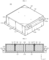
- FIG. 2 is a perspective view schematically showing a battery pack according to an embodiment of the present disclosure
- FIG. 3 is a partially exploded perspective view showing the battery pack of FIG. 2
- FIG. 4 is a perspective view schematically showing a battery module according to an embodiment of the present disclosure.
- a battery pack 10 includes a plurality of battery modules 100 and a pack case 200 for accommodating the battery modules 100.
- the pack case 200 includes a pack tray 210 for giving a space in which the plurality of battery modules 100 may be mounted, and a pack cover 220 coupled with the pack tray 210 to cover the entire battery modules 100.
- the battery pack 10 incorporates a beam frame (see FIG. 1 ) on the existing pack tray 210 into the battery modules 100 and also mechanically fixes and electrically connect the battery modules 100 to each other integrally with the pack cover 220, so there are advantages such as increased space utilization of the pack tray 210, simplified assembly process, and reduced number of fastening parts.
- the battery module 100 included in the battery pack 10 will be described first.
- the battery module 100 includes battery cells 110, a module case 120 for accommodating the battery cells 110 in an inner space thereof, and electrode terminals 150a, 150b exposed out of the module case 120.
- the battery cells 110 may be pouch-type secondary battery cells.
- the pouch-type battery cells 110 may be arranged in one direction in a state of standing upright so that their broad surfaces face each other in the inner space of the module case 120.
- each battery module 100 has a constant capacity and output voltage by connecting the battery cells 110 in series and/or in parallel.
- the battery cell 110 is replaced with a cylindrical secondary battery cell or a rectangular secondary battery cell.
- the module case 120 may include a base plate 121 and a top plate 122 for covering lower and upper portions of the battery cells 110, respectively, a pair of side plates 123 arranged at the outermost part of the battery cells 110 according to an arrangement direction thereof, and a front cover 124 and a rear cover 125 for covering front and rear sides of the battery cells 110, respectively.
- the base plate 121 which forms a bottom surface of the module case 120, functions like a conventional heatsink.
- a flow path through which a cooling water may flow is provided inside the base plate 121 so that the base plate 121 may directly cool the battery cells 110, and a cooling water port 121a is provided at an edge of the base plate to allow the cooling water to flow into and out of the flow path.
- the cooling water port 121a may extend vertically from one side of the edge of the base plate 121 to be directly connected to a cooling pipe 224 of the pack cover 220, explained later.
- a cooling water may be supplied to the base plate 121 of each battery module 100.
- a conventional battery pack 10 mostly has a cooling configuration in which a heat conduction pad and a heatsink are sequentially arranged under the battery module 100.
- the heatsink is incorporated to the base plate 121 of the module case 120, thereby reducing the heat transfer path, decreasing the number of parts, and saving the installation space of the cooling device, compared to the conventional art.
- the front cover 124 and the rear cover 125 are located at the front of the battery cells 110 so that the electrode leads of the battery cells 110 or components such as an inter connection board (ICB) are not exposed to the outside.
- IICB inter connection board
- the electrode terminals 150a, 150b include a positive electrode terminal 150a and a negative electrode terminal 150b, are located at an outer side of the top of the front cover 124 to have a rectangular plate shape so that its wide surface is placed horizontally so that bolts may be inserted therein in upper and lower directions.
- the electrode terminals 150a, 150b may be placed on and supported by a terminal support 126.
- the terminal support 126 is a part protruding from the front cover 124 and used as a place where a lower portion of the electrode terminals 150a, 150b is supported and a bolt of the battery module is fastened.
- the terminal support 126 may be provided to extend along a width direction of the front cover 124, and in a place where the positive electrode terminal 150a and the negative electrode terminal 150b are located, one hole into which a bolt may be inserted may be formed.
- a hole may also be provided such that a shoulder bolt is inserted in another place where the electrode terminals 150a, 150b are not located. In this way, the shoulder bolt may be fastened to the pack cover 220.
- the pair of side plate 123 may serve to compress and support the battery cells 110 from the outside at the outermost battery cell 110 along the arrangement direction of the battery cells 110.
- the battery module 100 of the present disclosure further includes a rigid beam 130 inside the module case 120.
- the rigid beam 130 is provided to have a predetermined thickness and an area corresponding to the wide surface of the battery cell 110, and may preferably be located in the middle of the battery cells 110 based on the arrangement order of the battery cells 110.
- the battery cells 110 are arranged such that the battery cells 110 are in close contact with both sides of the rigid beam 130.
- a group of battery cells 110 is located between the rigid beam 130 and one side plate 123, and another group of battery cells 110 is located between the rigid beam 130 and the other side plate 123.
- a buffer pad 140 may be further interposed between the battery cells 110 and the rigid beam 130.
- the rigid beam 130 is disposed in the middle of the battery cells 110, and even if the battery cells 110 undergo volume expansion (swelling) during charging and discharging, the rigid beam 130 plays a role of absorbing the expansion pressure of the battery cells 110, so that the side plates 123 of the module case are less pressurized. Therefore, the rigid beam 130 may be effective in preventing the deformation of the module case 120.
- top ends of the rigid beams 130 of the battery modules 100 may be integrally fastened by the pack cover 220 and a first fastening member B1 while the battery pack 10 is being assembled.
- Long bolts may be employed as the first fastening member B1, and the long bolts may be vertically fastened to the rigid beams 130 at the outside of the pack cover 220.
- the battery modules 100 may be fixed to the pack cover 220, and the pack cover 220 may also be supported by the rigid beams 130 to reinforce impact resistance.
- the rigid beams 130 are incorporated into the battery module 100 as above, a problem caused by the beam frame, which is a structure for reinforcing the rigidity of the pack tray 210 as mentioned in the background art, namely the conventional problems such as the occurrence of an unnecessary gap between the battery module 100 and the cross beam and the decrease of energy density of the battery pack 10 caused by the space occupancy of the cross beams, may be solved.
- the battery modules 100 are arranged in two rows on the pack tray 210, and the electrode terminals 150a, 150b may be arranged to face each other based on the center of the pack case 200. In this embodiment, four battery modules 100 are provided in total, but the number of battery modules 100 nay be increased or decreased. A positive electrode terminal of one battery module 100 may be connected to a negative electrode terminal of another neighboring battery module 100 by means of the terminal connection unit 221.
- At least one terminal connection unit 221 may be provided at an inner surface of the top end of the pack cover 220.
- the terminal connection unit 221 according to this embodiment includes an insulating bracket 221a fixedly coupled to the inner surface of the top end of the pack cover 220 and an inter-bus bar 221b made of a metal material, mounted to the bracket 221a and electrically connected with the electrode terminals 150a, 150b.
- positive electrode terminals and negative electrode terminals of two battery modules 100 adjacent in a Y-axis direction may be in contact with one end and the other end of the terminal connection unit 221 of the pack cover 220, respectively.
- both battery modules 100 may be connected in series.
- positive electrode terminals and negative electrode terminals of two battery modules 100 facing in an X-axis direction may also be connected in the same manner as above.
- the electrode terminals 150a, 150b and the terminal connection unit 221 may be integrally fastened to a second fastening member B2.
- the second fastening member B2 may be a bolt that is vertically inserted into the electrode terminals 150a, 150b and the terminal connection unit 221 to fasten them.
- the bolt B2 is inserted at the lower portion of the terminal support 126 to fasten the electrode terminals 150a, 150b to the terminal support 126. Accordingly, it is possible to secure the electrical connection of the battery modules 100 and the fixation with the pack cover 220 at once, thereby reducing bolt fastening points and simplifying the assembly process. In addition, since the battery modules 100 are fixed to the pack cover 220, the bolt fastening space between the battery modules 100 and the pack tray 210 may be eliminated, so that the space utilization rate of the upper surface of the pack tray 210 may be improved.
- the battery modules 100 are arranged in two rows inside the pack case 200, but the present disclosure is not necessarily limited thereto.
- the battery modules 100 may also be arranged in three or four or more rows.
- the battery modules 100 may be arranged in any way as long as the electrode terminals 150a, 150b of the battery modules 100 are arranged adjacent to each other and the electrode terminals 150a, 150b may be selectively connected by the terminal connection unit 221 when the upper portions of the battery modules 100 are covered with the pack cover 220.
- the pack cover 220 may include a cooling pipe 224 embedded therein along an edge region thereof.
- the cooling pipe 224 may be directly connected to the cooling water port 121a provided to the base plate 121 of each battery module 100.
- the pack cover 220 includes an uneven portion 222 fitted into the edge of the pack tray 210 and a cooling pipe mounting portion 223 extending from the uneven portion 222 into the pack cover 220.
- An O-ring 230 made of rubber and configured to reinforce the sealing property may be further interposed at the bonding portion between the pack cover 220 and the pack tray 210.
- the cooling pipe mounting portion 223 has an empty space provided to extend along a circumferential direction of the pack cover 220, and the cooling pipe 224 may be inserted into the empty space.
- the cooling pipe 224 may be omitted by forming a region of the cooling pipe mounting portion 223 in a hollow structure.
- the base plate 121 of each battery module 100 includes a port assembling portion 121b extending outward further based on a vertical surface of the rear cover.
- the cooling water port 121a may be provided upward in a vertical direction at the port assembling portion 121b.
- the port assembling portion 121b is disposed directly below the cooling pipe mounting portion 223 of the pack cover 220, and the cooling water port 121a is directly connected to the cooling pipe 224 of the pack cover 220.
- a fixing connector and a sealing member may be further used to secure fastening and sealing properties between the cooling water port 121a and the cooling pipe 224.
- the cooling water may be supplied to the base plate 121 of each battery module 100 while circulating in the circumferential direction of the pack cover 220 along the cooling pipe 224 of the pack cover 220, thereby absorbing the heat of the battery cells 110 during charging and discharging to maintain the battery cells 110 at an appropriate temperature.
- the cooling pipe 224 is included in the pack cover 220 and the cooling water port 121a of the base plate 121 is simply connected to the cooling pipe 224 by the shortest distance, the number of components such as additional connection pipes or hoses for circulating the cooling water may be reduced greatly.
- the battery module 100 and other electronic components may be mounted more easily.
- the battery pack 10 according to the present disclosure is assembled so that the battery modules 100 are fixed to the pack cover 220, unlike an assembling method of the conventional battery pack 10.
- the battery pack 10 of the present disclosure may be said as a reverse module assembling type.
- the pack cover 220 is turned over, and the battery modules 100 are disposed therein.
- the electrode terminals 150a, 150b of each battery module 100 are aligned with the corresponding terminal connection unit 221 of the pack cover 220 in an upper and lower direction, and the cooling water port 121a is prepared to be inserted into the cooling pipe 224 of the pack cover 220.
- the terminal support 126 and the electrode terminals 150a, 150b of each battery module 100 and the terminal connection unit 221 of the pack cover 220 are integrally fastened to secure electrical connection and mechanical fixation of each battery module 100.
- the O-ring 230 is interposed in the uneven portion 222 of the pack cover 220, and then the edge portion of the pack tray 210 is coupled to the uneven portion 222 by fitting.
- the battery pack 10 is turned over again, and the rigid beams 130 of each battery module 100 and the pack cover 220 are integrally fastened using the first fastening member B1.
- the battery pack 10 may further include various devices for controlling charging and discharging of the battery modules 100, such as a BMS, a current sensor and a fuse.
- the battery pack 10 may be applied not only to vehicles such as electric vehicles or hybrid electric vehicles. Of course, the battery pack 10 may be applied to energy storage systems or other IT products.
Landscapes
- Chemical & Material Sciences (AREA)
- Chemical Kinetics & Catalysis (AREA)
- Electrochemistry (AREA)
- General Chemical & Material Sciences (AREA)
- Engineering & Computer Science (AREA)
- Manufacturing & Machinery (AREA)
- Aviation & Aerospace Engineering (AREA)
- Battery Mounting, Suspending (AREA)
- Secondary Cells (AREA)
- Connection Of Batteries Or Terminals (AREA)
Claims (11)
- Bloc-batterie (10), qui comprend une pluralité de modules de batterie (100) et un boîtier de bloc (200) dans lequel les modules de batterie (100) sont installés à demeure, dans lequel le boîtier de bloc (200) comporte un plateau de bloc (210) situé au niveau d'une partie inférieure des modules de batterie (200), et un couvercle de bloc (220) couplé au plateau de bloc (210) pour recouvrir les modules de batterie (100), et chacun des modules de batterie (100) est couplé à demeure au couvercle de batterie (220) et comporte :des cellules de batterie (110) agencées dans une direction,un boîtier de module (120) pour loger les cellules de batterie (110) dans un espace interne de celui-ci, etune poutre rigide (130) disposée entre les cellules de batterie (110) à l'intérieur du boîtier de module (120),dans lequel la poutre rigide (130) est située au milieu des cellules de batterie (110) sur la base de l'ordre d'agencement de celles-ci et disposée de sorte que les deux surfaces latérales de celle-ci fassent face respectivement à une surface d'une cellule de batterie voisine de façon à bloquer l'expansion volumique des cellules de batterie (110).
- Bloc-batterie (10) selon la revendication 1,
dans lequel la poutre rigide (130) de chaque module de batterie (100) et le couvercle de bloc (220) sont reliés d'un seul tenant par un premier élément de fixation (B1) qui est fixé verticalement à l'extérieur du couvercle de bloc (220). - Bloc-batterie (10) selon la revendication 1,dans lequel le boîtier de module (120) comporte une plaque de base (121) située au niveau d'une partie inférieure des cellules de batterie (110) pour supporter les cellules de batterie (110), etdans lequel la plaque de base (121) présente un trajet d'écoulement disposé à l'intérieur de celle-ci de sorte qu'un liquide de refroidissement s'écoule à travers le trajet d'écoulement.
- Bloc-batterie (10) selon la revendication 3,dans lequel le couvercle de bloc (220) comporte un tuyau de refroidissement (224) encastré dans celui-ci le long d'une région de bord de celui-ci,dans lequel la plaque de base (121) comporte un orifice d'eau de refroidissement (121a) configuré pour communiquer avec le trajet d'écoulement et formé pour s'étendre verticalement, etdans lequel l'orifice d'eau de refroidissement (121a) est directement relié au tuyau de refroidissement (224) dans une direction supérieure et inférieure.
- Bloc-batterie (10) selon la revendication 4,
dans lequel le couvercle de bloc (220) comporte :une partie irrégulière (222) ajustée dans un bord du plateau de bloc (210), etune partie de montage de tuyau de refroidissement (223) s'étendant dans le couvercle de bloc (220) de sorte que le tuyau de refroidissement (224) soit inséré dans celui-ci. - Bloc-batterie (10) selon la revendication 1,dans lequel chacun des modules de batterie (100) comporte des bornes d'électrode (150a, 150b) faisant saillie horizontalement sur une surface latérale du bloc de module (120),le couvercle de bloc (220) comporte au moins une unité de connexion de bornes (221) au niveau d'une surface interne d'une extrémité supérieure de celui-ci, etla borne d'électrode (150a, 150b) d'un module de batterie (100) et la borne d'électrode (150a, 150b) d'un autre module de batterie (100) sont connectées électriquement par l'unité de connexion de bornes (221).
- Bloc-batterie (10) selon la revendication 6,
dans lequel l'unité de connexion de bornes (221) comporte :un support isolant (221a) couplé à demeure à une surface interne du couvercle de bloc (220) ; etune barre inter-bus (221b) montée sur le support isolant (221a) et connectée électriquement à la borne d'électrode (150a, 150b). - Bloc-batterie (10) selon la revendication 6,
dans lequel la borne d'électrode (150a, 150b) et l'unité de connexion de bornes (221) sont reliées d'un seul tenant par un deuxième élément de fixation (B2) qui est inséré verticalement dans la borne d'électrode (150a, 150b) et l'unité de connexion de bornes (221). - Bloc-batterie (10) selon la revendication 8,
dans lequel le boîtier de module (120) comporte en outre un support de borne (126) configuré pour supporter une partie inférieure de la borne d'électrode (150a, 150b), et dans lequel chaque module de batterie (100) est fixé au couvercle de bloc (220), et dans lequel le support de borne (126), la borne d'électrode (150a, 150b) et l'unité de connexion de bornes (221) sont reliés d'un seul tenant par le deuxième élément de fixation (B2). - Bloc-batterie (10) selon la revendication 1,
dans lequel la pluralité de modules de batterie (100) sont agencés en deux rangées de sorte que les bornes d'électrode (150a, 150b) de ceux-ci soient disposées de manière à se faire face sur la base d'une partie centrale du boîtier de bloc (200). - Véhicule, comprenant le bloc-batterie (10) selon l'une quelconque des revendications 1 à 10.
Applications Claiming Priority (2)
| Application Number | Priority Date | Filing Date | Title |
|---|---|---|---|
| KR1020190096282A KR102771554B1 (ko) | 2019-08-07 | 2019-08-07 | 배터리 모듈과 강성 빔을 통합하고 역방향 조립 방식을 채용한 배터리 팩 |
| PCT/KR2020/010350 WO2021025469A1 (fr) | 2019-08-07 | 2020-08-05 | Bloc-batterie incorporant un module de batterie et une poutre rigide et adoptant un procédé d'assemblage inverse |
Publications (3)
| Publication Number | Publication Date |
|---|---|
| EP3998652A1 EP3998652A1 (fr) | 2022-05-18 |
| EP3998652A4 EP3998652A4 (fr) | 2022-10-12 |
| EP3998652B1 true EP3998652B1 (fr) | 2023-11-22 |
Family
ID=74502785
Family Applications (1)
| Application Number | Title | Priority Date | Filing Date |
|---|---|---|---|
| EP20849740.4A Active EP3998652B1 (fr) | 2019-08-07 | 2020-08-05 | Bloc-batterie incorporant un module de batterie et une poutre rigide et adoptant un procédé d'assemblage inverse |
Country Status (9)
| Country | Link |
|---|---|
| US (1) | US12294071B2 (fr) |
| EP (1) | EP3998652B1 (fr) |
| JP (1) | JP7255016B2 (fr) |
| KR (1) | KR102771554B1 (fr) |
| CN (1) | CN114144927B (fr) |
| ES (1) | ES2967640T3 (fr) |
| HU (1) | HUE064466T2 (fr) |
| PL (1) | PL3998652T3 (fr) |
| WO (1) | WO2021025469A1 (fr) |
Families Citing this family (28)
| Publication number | Priority date | Publication date | Assignee | Title |
|---|---|---|---|---|
| KR20220041428A (ko) * | 2020-09-25 | 2022-04-01 | 주식회사 엘지에너지솔루션 | 전지 모듈, 전지팩 및 이를 포함하는 자동차 |
| CN113224452B (zh) * | 2021-03-26 | 2022-12-27 | 厦门海辰储能科技股份有限公司 | 电池包 |
| KR102946290B1 (ko) * | 2021-06-14 | 2026-03-30 | 주식회사 엘지에너지솔루션 | 안전성이 향상된 배터리 팩 |
| KR20230046394A (ko) * | 2021-09-30 | 2023-04-06 | 현대자동차주식회사 | 차량용 배터리 방열유닛 및 이를 포함한 차량용 배터리 케이스 |
| KR102664969B1 (ko) | 2022-01-26 | 2024-05-10 | 주식회사 엘지에너지솔루션 | 배터리팩 및 이를 구비한 자동차 |
| KR20240028583A (ko) * | 2022-08-24 | 2024-03-05 | 주식회사 엘지에너지솔루션 | 전지 모듈 및 이를 포함하는 전지팩 |
| KR102676203B1 (ko) * | 2022-09-07 | 2024-06-19 | 주식회사 엘지에너지솔루션 | 열 전파 지연구조를 구비하는 배터리 팩 |
| EP4539242A4 (fr) * | 2022-09-13 | 2025-12-24 | Lg Energy Solution Ltd | Module de batterie, bloc-batterie l?incluant et procédé de fabrication de module de batterie |
| US12580264B2 (en) * | 2022-11-18 | 2026-03-17 | Moment Energy Inc. | Battery tray |
| EP4475282A4 (fr) * | 2022-12-01 | 2026-03-04 | Lg Energy Solution Ltd | Bloc-batterie |
| JP2025527906A (ja) * | 2022-12-02 | 2025-08-22 | エルジー エナジー ソリューション リミテッド | バッテリーパック |
| CN116259900A (zh) * | 2023-04-23 | 2023-06-13 | 惠州亿纬锂能股份有限公司 | 电池包 |
| WO2024259751A1 (fr) * | 2023-06-19 | 2024-12-26 | 惠州亿纬锂能股份有限公司 | Bloc-batterie |
| KR102945997B1 (ko) | 2023-11-02 | 2026-04-01 | 디와이덕양주식회사 | 배터리 모듈의 기능을 대체하는 강성 강화 구조 |
| KR102711348B1 (ko) | 2023-11-02 | 2024-09-30 | 덕양산업 주식회사 | 개선된 공간 활용성과 강화된 강성을 구비하는 배터리 팩 |
| KR102763769B1 (ko) | 2023-11-02 | 2025-02-10 | 덕양산업 주식회사 | 균등 병렬 냉각 구조를 갖는 배터리 냉각 플레이트 |
| KR102774506B1 (ko) | 2023-11-02 | 2025-03-05 | 덕양산업 주식회사 | 개선된 단열 및 전자파 차폐 성능과 강화된 강성을 구비하는 배터리 팩 |
| KR102754965B1 (ko) | 2023-11-02 | 2025-01-22 | 덕양산업 주식회사 | 블록화된 기밀 구조 및 강화된 강성을 구비하는 배터리 팩 |
| KR102714706B1 (ko) | 2023-11-02 | 2024-10-14 | 덕양산업 주식회사 | 상하 냉각온도 편차를 개선하고 강화된 강성을 구비하는 배터리 냉각시스템 |
| KR102716111B1 (ko) | 2023-11-02 | 2024-10-14 | 덕양산업 주식회사 | 셀탭 냉각 구조와 강화된 강성을 구비하는 배터리 시스템 |
| KR102741924B1 (ko) | 2023-11-02 | 2024-12-17 | 덕양산업 주식회사 | 개선된 열전달 효율과 강화된 강성을 구비하는 배터리 팩 |
| KR102714327B1 (ko) | 2023-11-02 | 2024-10-14 | 덕양산업 주식회사 | 차체의 강성을 보강하는 강성이 강화된 배터리 팩 |
| KR20250081173A (ko) * | 2023-11-29 | 2025-06-05 | 주식회사 엘지에너지솔루션 | 배터리 팩 |
| KR20250090454A (ko) * | 2023-12-12 | 2025-06-20 | 주식회사 엘지에너지솔루션 | 배터리 모듈, 배터리 팩 및 이를 포함하는 자동차 |
| KR20250152346A (ko) * | 2024-04-16 | 2025-10-23 | 주식회사 엘지에너지솔루션 | 배터리 팩 및 이를 포함하는 자동차 |
| EP4651271A1 (fr) * | 2024-05-10 | 2025-11-19 | Eve Energy Co., Ltd. | Boîtier de batterie et bloc-batterie |
| JP2026007883A (ja) * | 2024-07-04 | 2026-01-19 | トヨタ自動車株式会社 | 蓄電装置 |
| CN120473647B (zh) * | 2025-07-08 | 2025-12-02 | 宁德时代新能源科技股份有限公司 | 电池装置、用电装置及储能装置 |
Family Cites Families (36)
| Publication number | Priority date | Publication date | Assignee | Title |
|---|---|---|---|---|
| JPH0752659A (ja) | 1993-08-19 | 1995-02-28 | Nissan Motor Co Ltd | 電気自動車のバッテリ固定構造 |
| JP2005340016A (ja) | 2004-05-27 | 2005-12-08 | Nec Lamilion Energy Ltd | フィルム外装電気デバイスモジュールおよび組電池システム |
| JP4786700B2 (ja) * | 2008-12-24 | 2011-10-05 | 三菱重工業株式会社 | 電池モジュール |
| KR101218751B1 (ko) | 2010-01-06 | 2013-01-07 | 주식회사 엘지화학 | 냉각 효율성이 향상된 중대형 전지팩 |
| KR101304220B1 (ko) * | 2011-12-23 | 2013-09-05 | 대동공업주식회사 | 전기차량용 배터리 커버 및 이를 포함하는 배터리 마운팅 장치 |
| KR101882007B1 (ko) * | 2012-07-18 | 2018-07-25 | 에스케이이노베이션 주식회사 | 전지팩 |
| KR101898295B1 (ko) | 2012-08-20 | 2018-09-12 | 에스케이이노베이션 주식회사 | 전지모듈 어셈블리 및 그 제조방법 |
| JP2014044884A (ja) | 2012-08-27 | 2014-03-13 | Sanyo Electric Co Ltd | バッテリシステム及びバッテリシステムを備える電動車両並びに蓄電装置 |
| JP5575209B2 (ja) * | 2012-11-21 | 2014-08-20 | 三菱重工業株式会社 | 電池モジュール |
| JP5638646B2 (ja) | 2013-02-28 | 2014-12-10 | 株式会社東芝 | 電子機器 |
| KR101649154B1 (ko) * | 2014-02-24 | 2016-08-18 | 엘지전자 주식회사 | 공기유로를 가지는 배터리팩 |
| KR20150134646A (ko) * | 2014-05-22 | 2015-12-02 | 주식회사 엘지화학 | 집전단자 연결용 버스바 및 이를 포함하는 파우치형 이차전지모듈 |
| DE102014217728A1 (de) | 2014-09-04 | 2016-03-10 | Mahle International Gmbh | Kühlplatte |
| KR101803958B1 (ko) | 2014-10-06 | 2017-12-28 | 주식회사 엘지화학 | 효율적인 냉각 구조의 전지팩 케이스 |
| KR101661972B1 (ko) * | 2015-02-17 | 2016-10-04 | 엘지전자 주식회사 | 전기자동차용 배터리 팩 |
| KR101883386B1 (ko) | 2015-03-16 | 2018-07-30 | 주식회사 엘지화학 | 전지 압축 저지체와 이를 포함하는 전지 모듈 |
| KR101674991B1 (ko) | 2016-01-15 | 2016-11-11 | 경상북도(농업기술원) | 개량된 조립구조를 갖는 농기계용 배터리 커버 |
| WO2017135232A1 (fr) | 2016-02-01 | 2017-08-10 | 株式会社オートネットワーク技術研究所 | Module de stockage d'électricité |
| JP6614012B2 (ja) | 2016-04-26 | 2019-12-04 | トヨタ自動車株式会社 | 車両のバッテリ搭載構造 |
| JP6808347B2 (ja) | 2016-04-28 | 2021-01-06 | キヤノン株式会社 | 液体吐出ヘッド及び液体吐出装置 |
| JP6597480B2 (ja) * | 2016-05-24 | 2019-10-30 | 株式会社豊田自動織機 | バスバー組付構造及び電池モジュール |
| KR20180035597A (ko) * | 2016-09-29 | 2018-04-06 | 주식회사 엘지화학 | 배터리 모듈 |
| KR102716516B1 (ko) | 2017-02-07 | 2024-10-14 | 에이치그린파워 주식회사 | 내연기관 자동차용 배터리 조립체 및 이의 조립 방법 |
| CN206558588U (zh) * | 2017-03-30 | 2017-10-13 | 华霆(合肥)动力技术有限公司 | 一种电池壳体及电源装置 |
| KR102172517B1 (ko) | 2017-04-04 | 2020-10-30 | 주식회사 엘지화학 | 크래쉬 빔 구조를 갖는 배터리 팩 |
| KR102065099B1 (ko) | 2017-04-04 | 2020-01-10 | 주식회사 엘지화학 | 크래쉬 빔과 배수 구조를 갖는 배터리 팩 |
| KR102256098B1 (ko) * | 2017-04-06 | 2021-06-03 | 주식회사 엘지에너지솔루션 | 루버 핀 형상의 열전도 매개체를 구비한 배터리 팩 |
| KR102162968B1 (ko) * | 2017-04-07 | 2020-10-07 | 주식회사 엘지화학 | 확장형 배터리 모듈 구조를 갖는 배터리 팩 |
| KR102258816B1 (ko) | 2017-06-27 | 2021-05-31 | 주식회사 엘지에너지솔루션 | 배터리 모듈 |
| US11217851B2 (en) * | 2017-09-07 | 2022-01-04 | Panasonic Intellectual Property Management Co., Ltd. | Battery module |
| KR102270234B1 (ko) * | 2017-12-12 | 2021-06-25 | 주식회사 엘지에너지솔루션 | 크로스 빔을 내장한 배터리 모듈 및 이를 포함하는 배터리 팩 |
| JP7203318B2 (ja) * | 2017-12-27 | 2023-01-13 | パナソニックIpマネジメント株式会社 | 電池パック |
| US10290970B1 (en) | 2018-02-08 | 2019-05-14 | Delphi Technologies, Llc | Connector with strain relief device |
| KR102703855B1 (ko) * | 2018-08-21 | 2024-09-05 | 에스케이온 주식회사 | 배터리 모듈 및 이의 제조방법 |
| CN110071243A (zh) | 2019-04-28 | 2019-07-30 | 深圳市富程威科技有限公司 | 一种电池模组 |
| KR20200134492A (ko) * | 2019-05-22 | 2020-12-02 | 현대자동차주식회사 | 열전모듈이 구비된 열교환기 및 이를 포함하는 배터리 열관리 시스템 |
-
2019
- 2019-08-07 KR KR1020190096282A patent/KR102771554B1/ko active Active
-
2020
- 2020-08-05 US US17/630,049 patent/US12294071B2/en active Active
- 2020-08-05 HU HUE20849740A patent/HUE064466T2/hu unknown
- 2020-08-05 WO PCT/KR2020/010350 patent/WO2021025469A1/fr not_active Ceased
- 2020-08-05 ES ES20849740T patent/ES2967640T3/es active Active
- 2020-08-05 JP JP2022506937A patent/JP7255016B2/ja active Active
- 2020-08-05 EP EP20849740.4A patent/EP3998652B1/fr active Active
- 2020-08-05 CN CN202080053338.7A patent/CN114144927B/zh active Active
- 2020-08-05 PL PL20849740.4T patent/PL3998652T3/pl unknown
Also Published As
| Publication number | Publication date |
|---|---|
| PL3998652T3 (pl) | 2024-04-08 |
| WO2021025469A1 (fr) | 2021-02-11 |
| EP3998652A4 (fr) | 2022-10-12 |
| US20220278389A1 (en) | 2022-09-01 |
| KR102771554B1 (ko) | 2025-02-20 |
| HUE064466T2 (hu) | 2024-03-28 |
| KR20210017273A (ko) | 2021-02-17 |
| CN114144927A (zh) | 2022-03-04 |
| CN114144927B (zh) | 2025-02-07 |
| ES2967640T3 (es) | 2024-05-03 |
| EP3998652A1 (fr) | 2022-05-18 |
| JP7255016B2 (ja) | 2023-04-10 |
| US12294071B2 (en) | 2025-05-06 |
| JP2022544094A (ja) | 2022-10-17 |
Similar Documents
| Publication | Publication Date | Title |
|---|---|---|
| EP3998652B1 (fr) | Bloc-batterie incorporant un module de batterie et une poutre rigide et adoptant un procédé d'assemblage inverse | |
| EP4007042B1 (fr) | Bloc-batterie du type à refroidissement de partie supérieure | |
| US12327875B2 (en) | Battery pack having integrated mechanical and electrical fixing structure of battery modules | |
| US20250266556A1 (en) | Battery Pack and Vehicle Comprising Same | |
| EP3748722B1 (fr) | Bloc-batterie comprenant une structure de montage | |
| US12095105B2 (en) | Battery pack including cover structure, electronic device and vehicle | |
| KR102770558B1 (ko) | 배터리 모듈 | |
| CN110167786A (zh) | 机架部件、与机架部件一体地形成的车辆电池系统以及包括其的集成电池系统车辆 | |
| KR20210125950A (ko) | 모듈 버스바를 포함하는 배터리 모듈, 및 그것을 포함한 배터리 팩, 및 전자 디바이스 | |
| CN114747074A (zh) | 电池模块、包括该电池模块的电池组和车辆 | |
| EP4135102B1 (fr) | Bloc-batterie et véhicule | |
| KR102353836B1 (ko) | 전지 팩 |
Legal Events
| Date | Code | Title | Description |
|---|---|---|---|
| STAA | Information on the status of an ep patent application or granted ep patent |
Free format text: STATUS: THE INTERNATIONAL PUBLICATION HAS BEEN MADE |
|
| PUAI | Public reference made under article 153(3) epc to a published international application that has entered the european phase |
Free format text: ORIGINAL CODE: 0009012 |
|
| STAA | Information on the status of an ep patent application or granted ep patent |
Free format text: STATUS: REQUEST FOR EXAMINATION WAS MADE |
|
| 17P | Request for examination filed |
Effective date: 20220209 |
|
| AK | Designated contracting states |
Kind code of ref document: A1 Designated state(s): AL AT BE BG CH CY CZ DE DK EE ES FI FR GB GR HR HU IE IS IT LI LT LU LV MC MK MT NL NO PL PT RO RS SE SI SK SM TR |
|
| REG | Reference to a national code |
Ref country code: DE Ref legal event code: R079 Free format text: PREVIOUS MAIN CLASS: H01M0002100000 Ipc: H01M0050204000 Ref document number: 602020021653 Country of ref document: DE |
|
| A4 | Supplementary search report drawn up and despatched |
Effective date: 20220914 |
|
| RIC1 | Information provided on ipc code assigned before grant |
Ipc: H01M 10/625 20140101ALI20220908BHEP Ipc: H01M 10/6556 20140101ALI20220908BHEP Ipc: H01M 50/204 20210101AFI20220908BHEP |
|
| DAV | Request for validation of the european patent (deleted) | ||
| DAX | Request for extension of the european patent (deleted) | ||
| GRAP | Despatch of communication of intention to grant a patent |
Free format text: ORIGINAL CODE: EPIDOSNIGR1 |
|
| STAA | Information on the status of an ep patent application or granted ep patent |
Free format text: STATUS: GRANT OF PATENT IS INTENDED |
|
| INTG | Intention to grant announced |
Effective date: 20230912 |
|
| GRAS | Grant fee paid |
Free format text: ORIGINAL CODE: EPIDOSNIGR3 |
|
| GRAA | (expected) grant |
Free format text: ORIGINAL CODE: 0009210 |
|
| STAA | Information on the status of an ep patent application or granted ep patent |
Free format text: STATUS: THE PATENT HAS BEEN GRANTED |
|
| P01 | Opt-out of the competence of the unified patent court (upc) registered |
Effective date: 20231002 |
|
| AK | Designated contracting states |
Kind code of ref document: B1 Designated state(s): AL AT BE BG CH CY CZ DE DK EE ES FI FR GB GR HR HU IE IS IT LI LT LU LV MC MK MT NL NO PL PT RO RS SE SI SK SM TR |
|
| REG | Reference to a national code |
Ref country code: GB Ref legal event code: FG4D |
|
| REG | Reference to a national code |
Ref country code: CH Ref legal event code: EP |
|
| REG | Reference to a national code |
Ref country code: DE Ref legal event code: R096 Ref document number: 602020021653 Country of ref document: DE |
|
| REG | Reference to a national code |
Ref country code: IE Ref legal event code: FG4D |
|
| REG | Reference to a national code |
Ref country code: NL Ref legal event code: FP |
|
| REG | Reference to a national code |
Ref country code: SE Ref legal event code: TRGR |
|
| REG | Reference to a national code |
Ref country code: LT Ref legal event code: MG9D |
|
| REG | Reference to a national code |
Ref country code: HU Ref legal event code: AG4A Ref document number: E064466 Country of ref document: HU |
|
| PG25 | Lapsed in a contracting state [announced via postgrant information from national office to epo] |
Ref country code: GR Free format text: LAPSE BECAUSE OF FAILURE TO SUBMIT A TRANSLATION OF THE DESCRIPTION OR TO PAY THE FEE WITHIN THE PRESCRIBED TIME-LIMIT Effective date: 20240223 |
|
| PG25 | Lapsed in a contracting state [announced via postgrant information from national office to epo] |
Ref country code: IS Free format text: LAPSE BECAUSE OF FAILURE TO SUBMIT A TRANSLATION OF THE DESCRIPTION OR TO PAY THE FEE WITHIN THE PRESCRIBED TIME-LIMIT Effective date: 20240322 |
|
| PG25 | Lapsed in a contracting state [announced via postgrant information from national office to epo] |
Ref country code: LT Free format text: LAPSE BECAUSE OF FAILURE TO SUBMIT A TRANSLATION OF THE DESCRIPTION OR TO PAY THE FEE WITHIN THE PRESCRIBED TIME-LIMIT Effective date: 20231122 |
|
| REG | Reference to a national code |
Ref country code: AT Ref legal event code: MK05 Ref document number: 1634696 Country of ref document: AT Kind code of ref document: T Effective date: 20231122 |
|
| PG25 | Lapsed in a contracting state [announced via postgrant information from national office to epo] |
Ref country code: AT Free format text: LAPSE BECAUSE OF FAILURE TO SUBMIT A TRANSLATION OF THE DESCRIPTION OR TO PAY THE FEE WITHIN THE PRESCRIBED TIME-LIMIT Effective date: 20231122 |
|
| PG25 | Lapsed in a contracting state [announced via postgrant information from national office to epo] |
Ref country code: LT Free format text: LAPSE BECAUSE OF FAILURE TO SUBMIT A TRANSLATION OF THE DESCRIPTION OR TO PAY THE FEE WITHIN THE PRESCRIBED TIME-LIMIT Effective date: 20231122 Ref country code: IS Free format text: LAPSE BECAUSE OF FAILURE TO SUBMIT A TRANSLATION OF THE DESCRIPTION OR TO PAY THE FEE WITHIN THE PRESCRIBED TIME-LIMIT Effective date: 20240322 Ref country code: GR Free format text: LAPSE BECAUSE OF FAILURE TO SUBMIT A TRANSLATION OF THE DESCRIPTION OR TO PAY THE FEE WITHIN THE PRESCRIBED TIME-LIMIT Effective date: 20240223 Ref country code: BG Free format text: LAPSE BECAUSE OF FAILURE TO SUBMIT A TRANSLATION OF THE DESCRIPTION OR TO PAY THE FEE WITHIN THE PRESCRIBED TIME-LIMIT Effective date: 20240222 Ref country code: AT Free format text: LAPSE BECAUSE OF FAILURE TO SUBMIT A TRANSLATION OF THE DESCRIPTION OR TO PAY THE FEE WITHIN THE PRESCRIBED TIME-LIMIT Effective date: 20231122 Ref country code: PT Free format text: LAPSE BECAUSE OF FAILURE TO SUBMIT A TRANSLATION OF THE DESCRIPTION OR TO PAY THE FEE WITHIN THE PRESCRIBED TIME-LIMIT Effective date: 20240322 |
|
| REG | Reference to a national code |
Ref country code: ES Ref legal event code: FG2A Ref document number: 2967640 Country of ref document: ES Kind code of ref document: T3 Effective date: 20240503 |
|
| PG25 | Lapsed in a contracting state [announced via postgrant information from national office to epo] |
Ref country code: RS Free format text: LAPSE BECAUSE OF FAILURE TO SUBMIT A TRANSLATION OF THE DESCRIPTION OR TO PAY THE FEE WITHIN THE PRESCRIBED TIME-LIMIT Effective date: 20231122 Ref country code: NO Free format text: LAPSE BECAUSE OF FAILURE TO SUBMIT A TRANSLATION OF THE DESCRIPTION OR TO PAY THE FEE WITHIN THE PRESCRIBED TIME-LIMIT Effective date: 20240222 Ref country code: LV Free format text: LAPSE BECAUSE OF FAILURE TO SUBMIT A TRANSLATION OF THE DESCRIPTION OR TO PAY THE FEE WITHIN THE PRESCRIBED TIME-LIMIT Effective date: 20231122 Ref country code: HR Free format text: LAPSE BECAUSE OF FAILURE TO SUBMIT A TRANSLATION OF THE DESCRIPTION OR TO PAY THE FEE WITHIN THE PRESCRIBED TIME-LIMIT Effective date: 20231122 |
|
| PG25 | Lapsed in a contracting state [announced via postgrant information from national office to epo] |
Ref country code: DK Free format text: LAPSE BECAUSE OF FAILURE TO SUBMIT A TRANSLATION OF THE DESCRIPTION OR TO PAY THE FEE WITHIN THE PRESCRIBED TIME-LIMIT Effective date: 20231122 |
|
| PG25 | Lapsed in a contracting state [announced via postgrant information from national office to epo] |
Ref country code: CZ Free format text: LAPSE BECAUSE OF FAILURE TO SUBMIT A TRANSLATION OF THE DESCRIPTION OR TO PAY THE FEE WITHIN THE PRESCRIBED TIME-LIMIT Effective date: 20231122 |
|
| PG25 | Lapsed in a contracting state [announced via postgrant information from national office to epo] |
Ref country code: SK Free format text: LAPSE BECAUSE OF FAILURE TO SUBMIT A TRANSLATION OF THE DESCRIPTION OR TO PAY THE FEE WITHIN THE PRESCRIBED TIME-LIMIT Effective date: 20231122 |
|
| PG25 | Lapsed in a contracting state [announced via postgrant information from national office to epo] |
Ref country code: SM Free format text: LAPSE BECAUSE OF FAILURE TO SUBMIT A TRANSLATION OF THE DESCRIPTION OR TO PAY THE FEE WITHIN THE PRESCRIBED TIME-LIMIT Effective date: 20231122 Ref country code: SK Free format text: LAPSE BECAUSE OF FAILURE TO SUBMIT A TRANSLATION OF THE DESCRIPTION OR TO PAY THE FEE WITHIN THE PRESCRIBED TIME-LIMIT Effective date: 20231122 Ref country code: RO Free format text: LAPSE BECAUSE OF FAILURE TO SUBMIT A TRANSLATION OF THE DESCRIPTION OR TO PAY THE FEE WITHIN THE PRESCRIBED TIME-LIMIT Effective date: 20231122 Ref country code: EE Free format text: LAPSE BECAUSE OF FAILURE TO SUBMIT A TRANSLATION OF THE DESCRIPTION OR TO PAY THE FEE WITHIN THE PRESCRIBED TIME-LIMIT Effective date: 20231122 Ref country code: DK Free format text: LAPSE BECAUSE OF FAILURE TO SUBMIT A TRANSLATION OF THE DESCRIPTION OR TO PAY THE FEE WITHIN THE PRESCRIBED TIME-LIMIT Effective date: 20231122 Ref country code: CZ Free format text: LAPSE BECAUSE OF FAILURE TO SUBMIT A TRANSLATION OF THE DESCRIPTION OR TO PAY THE FEE WITHIN THE PRESCRIBED TIME-LIMIT Effective date: 20231122 |
|
| REG | Reference to a national code |
Ref country code: DE Ref legal event code: R097 Ref document number: 602020021653 Country of ref document: DE |
|
| PLBE | No opposition filed within time limit |
Free format text: ORIGINAL CODE: 0009261 |
|
| STAA | Information on the status of an ep patent application or granted ep patent |
Free format text: STATUS: NO OPPOSITION FILED WITHIN TIME LIMIT |
|
| PG25 | Lapsed in a contracting state [announced via postgrant information from national office to epo] |
Ref country code: SI Free format text: LAPSE BECAUSE OF FAILURE TO SUBMIT A TRANSLATION OF THE DESCRIPTION OR TO PAY THE FEE WITHIN THE PRESCRIBED TIME-LIMIT Effective date: 20231122 |
|
| 26N | No opposition filed |
Effective date: 20240823 |
|
| PG25 | Lapsed in a contracting state [announced via postgrant information from national office to epo] |
Ref country code: SI Free format text: LAPSE BECAUSE OF FAILURE TO SUBMIT A TRANSLATION OF THE DESCRIPTION OR TO PAY THE FEE WITHIN THE PRESCRIBED TIME-LIMIT Effective date: 20231122 |
|
| REG | Reference to a national code |
Ref country code: CH Ref legal event code: PL |
|
| PG25 | Lapsed in a contracting state [announced via postgrant information from national office to epo] |
Ref country code: LU Free format text: LAPSE BECAUSE OF NON-PAYMENT OF DUE FEES Effective date: 20240805 |
|
| PG25 | Lapsed in a contracting state [announced via postgrant information from national office to epo] |
Ref country code: MC Free format text: LAPSE BECAUSE OF FAILURE TO SUBMIT A TRANSLATION OF THE DESCRIPTION OR TO PAY THE FEE WITHIN THE PRESCRIBED TIME-LIMIT Effective date: 20231122 Ref country code: CH Free format text: LAPSE BECAUSE OF NON-PAYMENT OF DUE FEES Effective date: 20240831 |
|
| REG | Reference to a national code |
Ref country code: BE Ref legal event code: MM Effective date: 20240831 |
|
| PG25 | Lapsed in a contracting state [announced via postgrant information from national office to epo] |
Ref country code: BE Free format text: LAPSE BECAUSE OF NON-PAYMENT OF DUE FEES Effective date: 20240831 |
|
| PG25 | Lapsed in a contracting state [announced via postgrant information from national office to epo] |
Ref country code: IE Free format text: LAPSE BECAUSE OF NON-PAYMENT OF DUE FEES Effective date: 20240805 |
|
| PGFP | Annual fee paid to national office [announced via postgrant information from national office to epo] |
Ref country code: NL Payment date: 20250722 Year of fee payment: 6 |
|
| PGFP | Annual fee paid to national office [announced via postgrant information from national office to epo] |
Ref country code: HU Payment date: 20250827 Year of fee payment: 6 |
|
| PG25 | Lapsed in a contracting state [announced via postgrant information from national office to epo] |
Ref country code: FI Free format text: LAPSE BECAUSE OF FAILURE TO SUBMIT A TRANSLATION OF THE DESCRIPTION OR TO PAY THE FEE WITHIN THE PRESCRIBED TIME-LIMIT Effective date: 20231122 |
|
| PGFP | Annual fee paid to national office [announced via postgrant information from national office to epo] |
Ref country code: ES Payment date: 20250911 Year of fee payment: 6 |
|
| PGFP | Annual fee paid to national office [announced via postgrant information from national office to epo] |
Ref country code: DE Payment date: 20250721 Year of fee payment: 6 |
|
| PGFP | Annual fee paid to national office [announced via postgrant information from national office to epo] |
Ref country code: TR Payment date: 20250723 Year of fee payment: 6 Ref country code: PL Payment date: 20250723 Year of fee payment: 6 Ref country code: IT Payment date: 20250722 Year of fee payment: 6 |
|
| PGFP | Annual fee paid to national office [announced via postgrant information from national office to epo] |
Ref country code: GB Payment date: 20250722 Year of fee payment: 6 |
|
| PGFP | Annual fee paid to national office [announced via postgrant information from national office to epo] |
Ref country code: FR Payment date: 20250725 Year of fee payment: 6 |
|
| PGFP | Annual fee paid to national office [announced via postgrant information from national office to epo] |
Ref country code: SE Payment date: 20250722 Year of fee payment: 6 |
|
| PG25 | Lapsed in a contracting state [announced via postgrant information from national office to epo] |
Ref country code: CY Free format text: LAPSE BECAUSE OF FAILURE TO SUBMIT A TRANSLATION OF THE DESCRIPTION OR TO PAY THE FEE WITHIN THE PRESCRIBED TIME-LIMIT; INVALID AB INITIO Effective date: 20200805 |