EP4000131B1 - Gruppenantenne mit mehreren paneelen - Google Patents
Gruppenantenne mit mehreren paneelen Download PDFInfo
- Publication number
- EP4000131B1 EP4000131B1 EP20736356.5A EP20736356A EP4000131B1 EP 4000131 B1 EP4000131 B1 EP 4000131B1 EP 20736356 A EP20736356 A EP 20736356A EP 4000131 B1 EP4000131 B1 EP 4000131B1
- Authority
- EP
- European Patent Office
- Prior art keywords
- radiating
- array antenna
- antenna
- panels
- shaping
- Prior art date
- Legal status (The legal status is an assumption and is not a legal conclusion. Google has not performed a legal analysis and makes no representation as to the accuracy of the status listed.)
- Active
Links
Images




Classifications
-
- H—ELECTRICITY
- H01—ELECTRIC ELEMENTS
- H01Q—ANTENNAS, i.e. RADIO AERIALS
- H01Q21/00—Antenna arrays or systems
- H01Q21/29—Combinations of different interacting antenna units for giving a desired directional characteristic
-
- H—ELECTRICITY
- H01—ELECTRIC ELEMENTS
- H01Q—ANTENNAS, i.e. RADIO AERIALS
- H01Q3/00—Arrangements for changing or varying the orientation or the shape of the directional pattern of the waves radiated from an antenna or antenna system
- H01Q3/26—Arrangements for changing or varying the orientation or the shape of the directional pattern of the waves radiated from an antenna or antenna system varying the relative phase or relative amplitude of energisation between two or more active radiating elements; varying the distribution of energy across a radiating aperture
-
- G—PHYSICS
- G01—MEASURING; TESTING
- G01S—RADIO DIRECTION-FINDING; RADIO NAVIGATION; DETERMINING DISTANCE OR VELOCITY BY USE OF RADIO WAVES; LOCATING OR PRESENCE-DETECTING BY USE OF THE REFLECTION OR RERADIATION OF RADIO WAVES; ANALOGOUS ARRANGEMENTS USING OTHER WAVES
- G01S7/00—Details of systems according to groups G01S13/00, G01S15/00, G01S17/00
- G01S7/02—Details of systems according to groups G01S13/00, G01S15/00, G01S17/00 of systems according to group G01S13/00
- G01S7/28—Details of pulse systems
- G01S7/2813—Means providing a modification of the radiation pattern for cancelling noise, clutter or interfering signals, e.g. side lobe suppression, side lobe blanking, null-steering arrays
-
- H—ELECTRICITY
- H01—ELECTRIC ELEMENTS
- H01Q—ANTENNAS, i.e. RADIO AERIALS
- H01Q21/00—Antenna arrays or systems
- H01Q21/06—Arrays of individually energised antenna units similarly polarised and spaced apart
- H01Q21/22—Antenna units of the array energised non-uniformly in amplitude or phase, e.g. tapered array or binomial array
Definitions
- the invention lies in the field of antenna devices, such as radar antennas, and relates more particularly to the production of a large array antenna.
- Array antennas are antennas whose radiating face is made up of elementary radiating elements mounted on a mechanical structure.
- the spacing between the radiating elements, or pitch of the radiating face, is fixed and is linked to the operating frequency band of the antenna.
- By modifying the phase of the signal transmitted or received by each of the radiating elements it is possible to direct the maximum gain of the antenna in a given direction, which makes them particularly suitable for radar applications aimed at scanning a geographical area or to follow the movement of a target over time (electronically scanned antennas).
- the radiation distribution function consists of a main lobe, or beam, and side lobes. Modifying the amplitude of the elementary signals also makes it possible to control the quality of the beams formed and advantageously their secondary lobe levels.
- the size of an array antenna is adjusted according to a specific operational need. Once the antenna is built, the performance of the antenna such as its gain or its angular resolution is fixed.
- the patent US 6,496,158 B1 describes a multi-panel antenna system in which the space between panels is adjusted to limit intermodulation products.
- the patent application FR 2.784.803 A1 deals with an antenna comprising several sub-arrays.
- the patent application US 4,596,986 A describes a method for canceling out jammers arriving in the secondary lobe of an array antenna.
- the patent application US 2009/135085 A1 describes a modular array antenna.
- the patent application US 2015/349434 A1 describes an array antenna formed from two arrays of radiating elements.
- the sum used to calculate the shaping coefficient applied to the radiating elements also includes a calibration coefficient.
- the shaping coefficient making it possible to orient the maximum gain of the antenna in a given direction is calculated from the desired pointing direction of the array antenna, the frequency of the radio frequency signal, the position of the radiating element considered within the array antenna, and the total number of radiating elements of the array antenna.
- the shaping coefficient making it possible to orient the maximum gain of the antenna in the direction of at least one secondary lobe resulting from gaps between the radiating panels of the array antenna is calculated from of the direction of said secondary lobe, of the frequency of the radio frequency signal, of the position of the radiating element considered within the array antenna, and of the total number of radiating elements of the array antenna.
- the array antenna further comprises means for summing the signals received from each of the radiating and shaped elements.
- the method further comprises a preliminary step of characterizing secondary lobes resulting from gaps between the radiating panels of the array antenna.
- the present invention proposes to respond to these problems by producing an array antenna from array antennas of smaller dimensions.
- it is possible to dynamically adjust the size and performance of the antenna according to the need for range, by adding or removing antennas.
- This association of elements independent from a mechanical point of view results in a large, high-performance radar whose transport and deployment is easy compared to the transport and deployment of an antenna of equivalent size.
- FIG. 1a schematically represents the radiating panel of a unitary array antenna. It comprises a radiating panel 100 composed of a plurality of radiating elements 101 distributed according to a mesh of regular pitch.
- the radio frequency (RF) signal to be transmitted is shaped and then transmitted by each of the radiating elements.
- Setting form consists of modifying the phase of the RF signal, and advantageously its amplitude, for each of the radiating elements independently so as to direct the maximum gain of the antenna in the desired direction.
- the RF signal received from each radiating element is shaped to obtain the maximum gain of the antenna in a given direction.
- the shaping of the beams is given by a control law, a phase law 103 and advantageously an amplitude law 102, to be applied to the RF signal to be transmitted or received on each of the radiating elements of the radiating panel.
- the applied phase shift makes it possible to orient the maximum gain of the antenna in the desired direction. This phase shift is constant between two consecutive radiating elements, and its value is directly linked to the wavelength of the RF signal, the pitch of the radiating face and the pointing of the desired beam.
- the amplitude control law makes it possible to concentrate the power at the center of the antenna, and therefore to reduce the level of secondary lobes.
- the amplitude control law is therefore advantageous but is not essential for pointing the antenna beam, most of the scanning array antennas known to the state of the art being controlled only by phase control. on the show.
- FIG. 1b represents a configuration of four disjoint unitary radiating panels, independent in the sense of the antenna arrays.
- the radiating panels 110, 111, 112 and 113 all focus in the same angular direction, without taking into account the presence of neighboring panels.
- the same control law 120, 121, 122, 123 is assigned to each of the radiating panels.
- the total signal transmitted is the recombination of each of the signals, which makes it possible to improve the transmission power.
- the signal received on each of the radiating panels can be summed in order to improve the signal-to-noise ratio.
- the angular resolution is not improved compared to the configuration of the figure 1a .
- the emissions from the different panels interfere, which causes loss of gain and the appearance of secondary lobes, particularly for significant offsets.
- FIG 1c represents a radiating panel 130 for an array antenna made from the joint association of four radiating panels of smaller size, as shown in figure 1a .
- the control law 131 applied to the radiating elements is adapted in relation to the total surface of the radiating panel 130, via a centralized calculation of the phases, and advantageously of the amplitudes, of focusing to be applied.
- the angular resolution and gain of the antenna are improved compared to the configuration of the figure 1a .
- this case is a theoretical case towards which we must aim, in which the radiant panel made from several joined radiant panels is continuous.
- the antennas have edges which make it impossible to obtain a perfect joined network like the one shown in Figure figure 1c .
- FIG 1d represents a radiating panel for an array antenna made from the disjoint association of four disjoint unit panels 141, 142, 143 and 144, as shown in figure 1a .
- the control law 150 applied to the radiating elements is adapted in relation to the total surface of the radiating panel 130, via a centralized calculation of the phases, and advantageously of the amplitudes, of focusing to be applied.
- the radiating panels cannot be arranged in a contiguous manner because of their edges, the overall network antenna is not continuous.
- the spaces 151, 152 and 153 between radiating panels (translation along three axes) and their alignment (rotations along three axes) result in breaks in the total radiating face.
- the object of the present invention consists of producing an array antenna from several radiating panels arranged side by side in a non-contiguous manner, as in the example of the figure 1d , and to modify the control law of the radiating elements so as to take into account the spaces and alignment differences between the various radiating panels during the formation of the beam.
- the overall antenna is seen as corresponding to the sum of two radiating surfaces: a first radiating surface corresponding to the entire surface of the radiating panels (including the spaces between radiating panels), and a second surface corresponding to the spaces between the radiating panels. This second surface is equivalent to a virtual network of small radiating surfaces generating interference which degrades the beam generated by the first surface.
- the spaces between radiating panels are small compared to the dimension of the latter (typically less than a few wavelengths) it is possible to evaluate the radiation diagram of the second surface, and to contrast it with the radiation diagram of the first surface to obtain an overall radiation pattern whose level of secondary lobes caused by the non-joint nature of the radiating panels is reduced. This is possible by modifying the amplitude and phase coefficients of the signals transmitted to the radiating elements forming the overall radiating surface.
- the radiating panels are arranged side by side horizontally, so as to increase the width of the overall array antenna, and thus improve the angular resolution in azimuth.
- they could equally be arranged side by side vertically to improve the angular resolution in elevation, or along both axes.
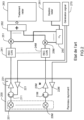
- FIG. 2 represents the main elements of a unitary array antenna according to the state of the art.
- array antenna encompasses both the radiating panels and the components necessary to implement the beamforming treatments.
- the array antennas presented below by way of illustration are used in reception, because for radar applications, the RF signal is generally transmitted using high efficiency amplifiers, such as for example amplifiers. class C, not allowing variation in amplitude of the transmitted signal. It is therefore in reception that the invention applies most completely, on the one hand for beams with low secondary lobe levels, and on the other hand because the modulation of signal control is possible in phase and in amplitude. However, the invention would be applied in the same way to control the beam in transmission.
- the radiant panel 200 of the figure 2 includes M radiating elements 201 to 20M.
- a circulator 211 to 21M makes it possible to switch each radiating element between a transmission function in which it receives a signal to be transmitted, and a reception function in which it receives an RF signal and transmits it to dedicated processing equipment.
- the RF signal to be transmitted is generated by dedicated equipment 270 for generating an analog RF signal, amplified by an amplification chain common to all the radiating elements or an amplification chain 221 at 22M specific to each radiating element, then emitted by the radiating elements.
- the signal received on each of the radiating elements is transmitted to a low noise amplifier 231 at 23M then digitized by an analog to digital converter 241 at 24M.
- a shaping coefficient specific to each radiating element ideally corresponding to a phase shift and an attenuation, is applied at 251 to 25M on the digital signal.
- the value of the phase shift and attenuation is adjustable and depends on the desired direction of the antenna beam.
- These coefficients are generally pre-calculated and stored in a table ⁇ 1260 including all the attenuation coefficients and phase shifts of the different radiating elements as a function of the direction of the antenna beam.
- the values of the table 260 are programmed according to the desired direction by a radar management device 261.
- the RF signals received from the different radiating elements and shaped are summed 262, then processed by the signal processing algorithms 263 specific to the intended application.
- the values in the table ⁇ 1260 are calculated theoretically from the number of radiating elements, their respective positions, the size and pitch of the radiating mesh, as well as the operating frequency considered.
- they can be supplemented by adjustment coefficients taking into account the imperfections of the radiation diagrams of each radiating element and the imperfections linked to the structure of the radiating panel, these imperfections being characterized in the factory during a calibration phase.
- a usual method consists of carrying out near field measurements of the antenna panel to obtain by back-propagation (inverse Fourier transform type calculation) the signal level produced for each radiating element and to know the deviation from the theoretical signal distribution giving maximum focus.
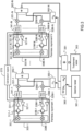
- FIG. 3 represents the main elements of an array antenna according to one embodiment of the invention.
- This antenna comprises N radiating panels 300-1, 300-N as described in figure 2 , connected to a centralized management device 361 of the control laws, as represented in figure 1d .
- Each radiating panel therefore comprises M radiating elements 301-1, 30M-1, 301-N, 30M-N, each connected to a circulator 311-1, 31M-1, 311-N, 31M-N allowing switching between emission and reception.
- the array antenna was composed of several radiating panels of strictly identical sizes.
- the invention would apply equivalently for an array antenna composed of radiating panels of different sizes.
- the results obtained would be comparable.
- the analog RF signal to be transmitted is generated by a device 370 and amplified by the amplification chains 321-1, 32M-1, 321-N, 32M-N.
- the signals received from each radiating element are amplified by the low noise amplifiers 331-1, 33M-1, 331-N, 33M-N, digitized by the analog-digital converters 341-1, 34M-1, 341- N, 34M-N, then shaped.
- the table of coefficients ⁇ 1 360-1 contains the attenuations and phase shifts applied to each of the RF signals received from the radiating elements 351-1, 35M-1 of the antenna 1, while the table of coefficients ⁇ N 360-N contains the attenuations and phase shifts applied to the RF signals received from the radiating elements 351-N, 35M-N of the antenna N.
- the signals are then summed by adders 362-1 and 362-N.
- the shaping coefficients ⁇ 1 and ⁇ N are provided by a higher level table 380, which includes the coefficient tables for one or more radiant panel configurations.
- a centralized radar management device 361 is responsible for calculating or selecting the coefficient tables based on the arrangement information of the radiating panels, the operating frequency and the intended orientation of the antenna beam.
- This device is generally in the form of software embedded on a calculation device such as a processor, a digital signal processor (better known by the English acronym DSP for “Digital Signal Processor”), or a specialized circuit. such as an ASIC (English acronym for “Application Specifies Integrated Circuit”) or an FPGA (English acronym for “Field-Programmable Gate Array”).
- the signals received from the different antennas are summed 381, then transmitted to radar processing software 363 for the implementation of the signal processing algorithms necessary for the targeted applications.
- the multi-panel antenna according to the invention has the advantage that the control law of the weightings applied to the RF signals received from the different radiating elements takes into account the entire radiating face of the multi-panel antenna, the frequency of operation and the desired pointing direction, but also the imperfections due to breaks in the radiating face caused by the spaces between radiating panels and their alignment variations.
- FIG 4a represents, in dotted lines 401, the radiation diagram obtained by the implementation of an ideal joined network of radiating panels, as represented in figure 1c .
- the radiation pattern is shown for angles between -90° and +90°.
- the main lobe which corresponds to the pointing direction of the beam, points in the example at 50° azimuth. In other directions, emissions are attenuated by at least 35 dB relative to the main lobe.
- FIG 4a also represents, in solid lines 402, the radiation diagram obtained by the implementation of a disjoint network of radiating panels, as represented in figure 1d , without compensation for interference generated by gaps between panels.
- Side lobes whose level is approximately 20 dB to 30 dB below the level of the main lobe, appear at angles of approximately -70°, -45°, -25°, -5° and 30°.
- One of the aims of the invention is to reduce the level or eliminate these secondary lobes, which are here approximately 10 to 20 dB higher than for the joined network.
- the first term of the equation, in W c [ K p , ( r ⁇ n ⁇ ) m ], corresponds to the P shaping coefficients ⁇ c which must be applied to each of the radiating elements to point the beam of the array antenna in each of the P directions K p of the secondary lobes of the antenna, when we consider a control law taking into account the entire network antenna, i.e. W vs K p ⁇ r ⁇ not ⁇ m ⁇ ⁇ vs K p ⁇ r ⁇ 1 ⁇ m ⁇ 1 . . M ⁇ 1 ⁇ ... ⁇ vs K p ⁇ r ⁇ NOT ⁇ m ⁇ 1 . . M ⁇ NOT ⁇ .
- the corresponding shaping coefficient ⁇ c is obtained from the associated control law making it possible to point the beam of the array antenna in the direction of the secondary lobe considered, at the desired level. It is therefore a complex amplitude/phase coefficient.
- the coefficient ⁇ co can therefore correspond to a phase shift only, or advantageously be a complex amplitude/phase coefficient.
- the third term of the equation, in W [ k , ( r_r ⁇ n ⁇ ) m ], corresponds to the phase factor of the signal captured by each radiating element to take into account interference between the radiating elements.
- This phase factor may contain a calibration coefficient generally obtained during a calibration phase carried out during the manufacture of each radiating panel.
- the invention proposes to apply to each of the radiating elements a complex shaping coefficient calculated on the principle of subtraction in the known direction of each of the parasitic lobes of an equivalent lobe of level equal to that of the parasitic lobe.
- Knowledge of the parasitic lobe is determined by knowledge of the position of the elements of the global network installed on its site of use.
- the coefficient of a radiating element is equal to the coefficient ⁇ co , required to orient the maximum gain of the antenna in a given direction, minus the coefficients ⁇ c corresponding to the directions of the secondary lobes affected by the levels of the parasitic secondary lobes. In this way, the effect of the spaces between radiating panels is compensated and the level of the secondary lobes reduced.
- phase and amplitude shaping coefficient applied to each radiating element takes into account the calibration coefficient taken into account in the W of equation (1).
- figure 4b represents, in dotted lines 411, the radiation diagram obtained by a disjoint network of radiating panels, as shown in figure 1d , without compensation for interference due to gaps between panels, corresponding to the 402 radiation pattern of the figure 4a .
- the radiation diagram 412 in solid lines, is obtained by the same disjoint network of radiating panels, after implementation of the compensation of the shaping coefficients described by the invention.
- the secondary lobes at -70°, -45°, -25°, -5° and 30° have been attenuated and returned to levels comparable to those obtained for an ideal antenna composed of joined radiating panels, i.e. a reduction of 10 to 20dB in the level of each of these secondary lobes.
- the multi-antenna radiating panel according to the invention therefore makes it possible to reduce the level of secondary lobes generated by the gaps between radiating panels.
- the number of side lobes generated by the spaces between radiating panels depends on the operating frequency and the pointing direction.
- the number P of secondary lobes processed depends on their level and the requirements on the directivity of the beam, and must therefore be evaluated with regard to operational needs and the available computing power.
- FIG 5a represents the beam of an array antenna made up of an ideal joined array of radiating panels.
- the beam is well centered around the intended direction.
- FIG 5b represents the antenna beam emitted by the same ideal joined array of radiating panels when the phase and amplitude control coefficients are modified to take into account the interference generated by the spaces between the radiating panels.
- the beam is more diffuse than that of the figure 5a .
- the beam tends towards that of the figure 5a .
- the two parts can be implemented independently. Indeed, the first can be carried out before installing the antenna for use in the field of operation since the interference generated is identical for two situations where the number of radiating panels and their arrangement is similar.
- the characterization of the interference can then be made during the installation of the antenna, beforehand, from the radiating panels used to constitute the network antenna, from other radiating panels of the same sizes, or even from software for simulating network antenna radiation.
- N radiating panels are arranged side by side, horizontally, vertically or in both directions.
- the relative positions of the radiating panels that is to say the differences between these different panels and their orientations, are recorded and stored in a memory.
- these positions can be obtained by measurements carried out by metrology measuring equipment integrated into the radar such as laser range finders.
- the array antenna is configured to emit an RF signal in a given pointing direction, preferably in an environment reproducing the propagation of the signal in free space, such as for example an anechoic chamber.
- the maximum gain of the antenna is oriented by shaping the RF signal transmitted to each of the radiating elements, considering a global control law taking into account the entire network antenna.
- the antenna radiation pattern is then measured, in order to identify the direction of the secondary lobes generated by the gaps between the radiating panels. The operation is repeated for each of the pointing directions considered in the operational context.
- the characterization can also be carried out in software.
- a model corresponding to the multi-radiating panel array antenna is constituted in digital simulation software implemented in order to measure the radiation pattern, and to identify the directions and levels of the secondary lobes associated with each direction. envisaged pointing of the antenna.
- the direction of the secondary lobes generated by the gaps between radiating panels of the multi-panel array antenna is known for the intended pointing directions. These directions are stored in a memory allowing access to them when implementing the array antenna.
- steps 601 and 602 can be repeated for different arrangements of the radiating panels, by varying their number and/or their respective arrangements (positions and/or gaps).
- the method also includes a step 603 of implementing the transmission and/or reception of RF signals taking into account the position of the secondary lobes as a function of the arrangement of the radiating panels.
- a step 603 of implementing the transmission and/or reception of RF signals taking into account the position of the secondary lobes as a function of the arrangement of the radiating panels.
- Figure 7 represents in more detail this step of implementing a transmission/reception method on a multi-panel antenna according to one embodiment of the invention.
- a device for centralized management of control laws such as device 361 shown in Figure 3 , is configured to take into account the relative position 701 of the antenna panels and the position 702 of the radiating elements within each radiating panel to determine an absolute position 703 of each of the radiating elements within the array antenna.
- Operating parameters 704 are known to the centralized device, including a desired azimuth and elevation for pointing 705 of the antenna beam, as well as an operating frequency 706.
- the antenna management device is configured to calculate the control law making it possible to determine the set of coefficients W co 707 applicable to the network antenna to direct the antenna beam in the desired pointing direction, without taking into account the interference generated by the use of different panels radiant.
- the antenna management device is also configured to calculate the control law(s) making it possible to determine the set of coefficients W c 708 applicable to the network antenna to attenuate the rises of linked secondary lobes due to the use of different radiant panels. These coefficients are calculated from the information concerning the secondary lobes stored in memory during step 602, selected as a function of the arrangement of radiating panels, the targeted pointing direction and the operating frequency of the antenna.
- the antenna management device is also configured to retrieve from a memory a set of calibration coefficients W 709 corresponding to factory settings 710 associated with the radiating elements for the operating frequency 706.
- the antenna management device is also configured to calculate an overall shaping coefficient 711 for each of the radiating elements, corresponding to the sum of the coefficient ⁇ co (from the set of coefficients W co 707) with the opposite of the P coefficients ⁇ c (from the set of coefficients W c 708), supplemented where appropriate by the associated calibration coefficient (from the set of coefficients W 709).
- Each global shaping coefficient is used to shape the signals received from the corresponding radiating element 712 of the array antenna.
- Treatments 707, 708 and 711 of the Figure 7 are made at each change of one of the operating parameters 704, such as the pointing direction of the antenna, the frequency or the number/arrangement 701 of the radiating panels.
- the coefficients W c corresponding to the shaping coefficients applicable to the radiating elements to reduce the level of the secondary lobes for each of the pointing directions considered are calculated during step 602 of characterizing the secondary lobes, then stored in a memory allowing access to them during implementation of the array antenna.
- Step 708 is then limited to the selection of the set of coefficients corresponding to the arrangement and operating parameters of the array antenna.
- the sets of shaping coefficients stored in memory correspond to the sum of the coefficient W co and the opposite of the coefficient(s) W c for each radiating element of the antenna.
- This new set of coefficients is associated with parameters concerning the pointing direction, frequency and arrangement of the radiating panels.
- the calibration coefficients W are also taken into account in the sum stored in memory during step 602.
- the array antenna which is the subject of the present invention consists of a plurality of independent radiating panels connected to a centralized device for managing beam formation. It therefore responds well to the expressed need for ease of adaptation of performance to operational needs since it is enough to add radiating panels to increase the size of the antenna and therefore improve its performance. It also responds well to the need for ease of transport and deployment because the elements that compose it are mechanically independent, and can be transported independently. Finally, its implementation complexity is low since the interference generated by the different panels can be characterized and shaping parameters calculated before the implementation of the antenna on the field of operations.
Landscapes
- Engineering & Computer Science (AREA)
- Radar, Positioning & Navigation (AREA)
- Remote Sensing (AREA)
- Computer Networks & Wireless Communication (AREA)
- Physics & Mathematics (AREA)
- General Physics & Mathematics (AREA)
- Variable-Direction Aerials And Aerial Arrays (AREA)
Claims (7)
- Gruppenantenne, die Folgendes umfasst:- eine Vielzahl von nebeneinander angeordneten mechanisch disjunkten Strahlplatten (300-1, 300-N), wobei jede Strahlplatte eine Vielzahl von Strahlelementen (301-1, 30M-1, 301-N, 30M-N) umfasst,- Mittel (351-1, 35M-1, 351-N, 35M-N) zum Anwenden einer Formung auf Hochfrequenzsignale, die von jedem Strahlelement gesendet oder davon empfangen werden, und- eine Vorrichtung (361) zum Verwalten der Mittel zum Anwenden von Formung auf die Hochfrequenzsignale,wobei die Mittel zum Anwenden von Formung zum Anwenden eines komplexen Formungskoeffizienten auf das von jedem Abstrahlelement gesendete oder davon empfangene Signal konfiguriert sind,wobei die Gruppenantenne dadurch gekennzeichnet ist, dass der komplexe Formungskoeffizient einer Summe entspricht zwischen mindestens:∘ einem Formungskoeffizienten (Wco ), der es zulässt, den maximalen Gewinn der Antenne in eine gegebene Richtung zu orientieren, und∘ mindestens dem Gegenteil eines Formungskoeffizienten (Wc ), der es zulässt, den maximalen Gewinn der Antennen in die Richtung einer Nebenkeule zu lenken, die aus Abständen zwischen den Strahlplatten der Gruppenantenne resultiert.
- Gruppenantenne nach Anspruch 1, wobei die Summe, die zum Berechnen des auf die Strahlelemente angewandten Formungskoeffizienten verwendet wird, ferner einen Kalibrierungskoeffizienten (W) enthält.
- Gruppenantenne nach einem der vorhergehenden Ansprüche, wobei der Formungskoeffizient (Wco ), der es zulässt, den maximalen Gewinn der Antenne in eine gegebene Richtung zu orientieren, auf der Basis der gewünschten Zeigerichtung der Gruppenantenne, der Frequenz des Hochfrequenzsignals, der Position des betrachteten Strahlelements innerhalb der Gruppenantenne und der Gesamtzahl der Strahlelemente der Gruppenantenne berechnet wird.
- Gruppenantenne nach einem der vorhergehenden Ansprüche, wobei der Formungskoeffizient (Wc ), der es zulässt, den maximalen Gewinn der Antenne in der Richtung mindestens einer Nebenkeule zu orientieren, die aus Abständen zwischen den Strahlplatten der Gruppenantenne resultiert, auf der Basis der Richtung der Nebenkeule, der Frequenz des Hochfrequenzsignals, der Position des betrachteten Strahlelements innerhalb der Gruppenantenne und der Gesamtzahl der Strahlelemente der Gruppenantenne berechnet wird.
- Gruppenantenne nach einem der vorhergehenden Ansprüche, die zum Empfangen eines Hochfrequenzsignals verwendet wird und ferner Mittel (362-1, 362-N, 381) zur Summierung der von jedem der Strahl- und geformten Elemente empfangenen Signale umfasst.
- Verfahren zum Senden oder Empfangen eines Hochfrequenzsignals für eine Gruppenantenne, das eine Vielzahl von nebeneinander angeordneten Strahlplatten (300-1, 300-N) umfasst, wobei jede Strahlplatte eine Vielzahl von Strahlelementen (301-1, 30M-1, 301-N, 30M-N) umfasst, wobei das Verfahren das Anwenden (603) eines komplexen Formungskoeffizienten (711) auf das von jedem Strahlelement gesendete oder davon empfangene Signal umfasst, dadurch gekennzeichnet, dass der Formungskoeffizient einer Summe entspricht zwischen mindestens:∘ einem Formungskoeffizienten (707), der es zulässt, den maximalen Gewinn der Antenne in eine gegebene Richtung zu orientieren, und∘ mindestens dem Gegenteil eines Formungskoeffizienten (708), der es zulässt, den maximalen Antennengewinn in die Richtung einer Nebenkeule zu lenken, die aus Abständen zwischen den Strahlplatten der Gruppenantenne resultiert.
- Verfahren zum Senden oder Empfangen eines Hochfrequenzsignals nach dem vorhergehenden Anspruch, das ferner einen Vorabschritt (602) des Charakterisierens von Nebenkeulen umfasst, die aus Abständen zwischen den Strahlplatten der Gruppenantenne resultieren.
Applications Claiming Priority (2)
| Application Number | Priority Date | Filing Date | Title |
|---|---|---|---|
| FR1908058A FR3099003B1 (fr) | 2019-07-18 | 2019-07-18 | Antenne reseau multi-panneaux |
| PCT/EP2020/069293 WO2021008977A1 (fr) | 2019-07-18 | 2020-07-08 | Antenne reseau multi-panneaux |
Publications (2)
| Publication Number | Publication Date |
|---|---|
| EP4000131A1 EP4000131A1 (de) | 2022-05-25 |
| EP4000131B1 true EP4000131B1 (de) | 2023-11-29 |
Family
ID=69157924
Family Applications (1)
| Application Number | Title | Priority Date | Filing Date |
|---|---|---|---|
| EP20736356.5A Active EP4000131B1 (de) | 2019-07-18 | 2020-07-08 | Gruppenantenne mit mehreren paneelen |
Country Status (6)
| Country | Link |
|---|---|
| US (1) | US11916300B2 (de) |
| EP (1) | EP4000131B1 (de) |
| ES (1) | ES2972956T3 (de) |
| FI (1) | FI4000131T3 (de) |
| FR (1) | FR3099003B1 (de) |
| WO (1) | WO2021008977A1 (de) |
Family Cites Families (7)
| Publication number | Priority date | Publication date | Assignee | Title |
|---|---|---|---|---|
| US4596986A (en) * | 1983-08-29 | 1986-06-24 | The United States Of America As Represented By The Secretary Of The Navy | Sidelobe canceller with adaptive antenna subarraying using a weighted Butler matrix |
| JP2561028B2 (ja) * | 1994-05-26 | 1996-12-04 | 日本電気株式会社 | サイドローブキャンセラ |
| EA002275B1 (ru) * | 1998-10-19 | 2002-02-28 | Научно-Исследовательский Электромеханический Институт (Ниэми) | Антенна для малогабаритных станций обнаружения и сопровождения целей и ракет |
| US6496158B1 (en) * | 2001-10-01 | 2002-12-17 | The Aerospace Corporation | Intermodulation grating lobe suppression method |
| US8081134B2 (en) * | 2007-09-17 | 2011-12-20 | The Boeing Company | Rhomboidal shaped, modularly expandable phased array antenna and method therefor |
| US8144051B2 (en) * | 2008-09-05 | 2012-03-27 | Raytheon Company | Adaptive sidelobe blanking for motion compensation |
| JP6409676B2 (ja) * | 2014-06-03 | 2018-10-24 | 三菱電機株式会社 | 衛星通信用アレイアンテナおよびアンテナ |
-
2019
- 2019-07-18 FR FR1908058A patent/FR3099003B1/fr not_active Expired - Fee Related
-
2020
- 2020-07-08 WO PCT/EP2020/069293 patent/WO2021008977A1/fr not_active Ceased
- 2020-07-08 EP EP20736356.5A patent/EP4000131B1/de active Active
- 2020-07-08 ES ES20736356T patent/ES2972956T3/es active Active
- 2020-07-08 FI FIEP20736356.5T patent/FI4000131T3/fi active
- 2020-07-08 US US17/628,136 patent/US11916300B2/en active Active
Also Published As
| Publication number | Publication date |
|---|---|
| US20220271444A1 (en) | 2022-08-25 |
| WO2021008977A1 (fr) | 2021-01-21 |
| FR3099003A1 (fr) | 2021-01-22 |
| FI4000131T3 (fi) | 2024-02-19 |
| FR3099003B1 (fr) | 2021-07-16 |
| EP4000131A1 (de) | 2022-05-25 |
| ES2972956T3 (es) | 2024-06-17 |
| US11916300B2 (en) | 2024-02-27 |
Similar Documents
| Publication | Publication Date | Title |
|---|---|---|
| EP2434310B1 (de) | Radar mit großer Winkelabdeckung an Bord von Flugzeugen mit Autopilot, insbesondere zum Ausweichen von Hindernissen | |
| FR2833356A1 (fr) | Radar a ondes de surface | |
| EP0097073A1 (de) | Verfahren und Vorrichtung zur Verringerung des Störsignalpegels, empfangen über die Nebenzipfel einer Radarantenne | |
| EP3463691B1 (de) | Anordnung von ultraschallwandlerelementen | |
| EP2380235B1 (de) | System zur elektromagnetischen strahlenemission mit einem antennennetzwerk | |
| EP3828586B1 (de) | Radar, fluggerät, das einen solchen radar umfasst, verarbeitungsverfahren in einem an bord eines fluggeräts eingebauten radars und entsprechendes computerprogramm | |
| EP3159965A1 (de) | Antennennetzsender für ein monoimpulsradarsystem | |
| EP4092928B1 (de) | Planare netzantenne | |
| EP4000131B1 (de) | Gruppenantenne mit mehreren paneelen | |
| EP3945636B1 (de) | Verfahren zur veränderung des strahlungsdiagramms eines antennennetzes und radar zur umsetzung eines solchen verfahrens | |
| EP4503479A1 (de) | Verbessertes fernfeldkalibrierungsverfahren für eine gruppenantenne und kalibrierte gruppenantenne | |
| EP1533866B1 (de) | Adaptive Phasengesteuerte Gruppenantenne mit digitaler Keulenformung | |
| JP4072149B2 (ja) | 分散開口アンテナ装置 | |
| EP2887090B1 (de) | Eichung eines Senders oder Empfängers von polarimetrischen Radarimpulsen | |
| WO2020136059A1 (fr) | Procede d'integration d'une antenne " reseaux " dans un milieu de nature electromagnetique differente et antenne associee | |
| EP3497747B1 (de) | Seitenrollgesteuerter radar zur autonomen lenkung einer plattform und selbstlenkender flugkörper mit solch einem radar | |
| EP4184801A1 (de) | Aktive mehrstrahl-gruppenantenne mit einer hybridvorrichtung zur bildung von richtstrahlen | |
| EP3155689B1 (de) | Flachantenne zur satellitenkommunikation | |
| EP1233282B1 (de) | Vorrichtung mit verteilten Sende- und Empfangsantennen, insbesondere für Radar mit synthetischer Emission und Strahlbildung | |
| EP3457174B1 (de) | Kompensationsverfahren der fehlausrichtung einer antenne in einem sar-bild, und radar, der dieses verfahren anwendet | |
| FR3136600A1 (fr) | Procédé de réalisation d'une antenne réseau dont les éléments rayonnants sont montés sur une surface de support courbe | |
| EP3237924B1 (de) | Verfahren zur messung einer einfallsrichtung einer einfallenden welle für sofortbreitbandempfänger und zugehöriger empfänger | |
| FR3112034A1 (fr) | Procédé de modification d’une ouverture d’au moins un faisceau d’un réseau d’antennes de communication radio et dispositif correspondant | |
| FR2553938A1 (fr) | Procede et dispositif de traitement de signaux radioelectriques hyperfrequences, en particulier pour l'obtention de diagrammes de rayonnement a pseudopodes | |
| EP3521851A1 (de) | Vorrichtung und verfahren zum senden/empfangen von funksignalen |
Legal Events
| Date | Code | Title | Description |
|---|---|---|---|
| STAA | Information on the status of an ep patent application or granted ep patent |
Free format text: STATUS: UNKNOWN |
|
| STAA | Information on the status of an ep patent application or granted ep patent |
Free format text: STATUS: THE INTERNATIONAL PUBLICATION HAS BEEN MADE |
|
| PUAI | Public reference made under article 153(3) epc to a published international application that has entered the european phase |
Free format text: ORIGINAL CODE: 0009012 |
|
| STAA | Information on the status of an ep patent application or granted ep patent |
Free format text: STATUS: REQUEST FOR EXAMINATION WAS MADE |
|
| 17P | Request for examination filed |
Effective date: 20220111 |
|
| AK | Designated contracting states |
Kind code of ref document: A1 Designated state(s): AL AT BE BG CH CY CZ DE DK EE ES FI FR GB GR HR HU IE IS IT LI LT LU LV MC MK MT NL NO PL PT RO RS SE SI SK SM TR |
|
| DAV | Request for validation of the european patent (deleted) | ||
| DAX | Request for extension of the european patent (deleted) | ||
| P01 | Opt-out of the competence of the unified patent court (upc) registered |
Effective date: 20230427 |
|
| GRAP | Despatch of communication of intention to grant a patent |
Free format text: ORIGINAL CODE: EPIDOSNIGR1 |
|
| STAA | Information on the status of an ep patent application or granted ep patent |
Free format text: STATUS: GRANT OF PATENT IS INTENDED |
|
| INTG | Intention to grant announced |
Effective date: 20230717 |
|
| GRAJ | Information related to disapproval of communication of intention to grant by the applicant or resumption of examination proceedings by the epo deleted |
Free format text: ORIGINAL CODE: EPIDOSDIGR1 |
|
| GRAP | Despatch of communication of intention to grant a patent |
Free format text: ORIGINAL CODE: EPIDOSNIGR1 |
|
| GRAS | Grant fee paid |
Free format text: ORIGINAL CODE: EPIDOSNIGR3 |
|
| INTG | Intention to grant announced |
Effective date: 20230926 |
|
| GRAA | (expected) grant |
Free format text: ORIGINAL CODE: 0009210 |
|
| STAA | Information on the status of an ep patent application or granted ep patent |
Free format text: STATUS: THE PATENT HAS BEEN GRANTED |
|
| RAP3 | Party data changed (applicant data changed or rights of an application transferred) |
Owner name: THALES |
|
| AK | Designated contracting states |
Kind code of ref document: B1 Designated state(s): AL AT BE BG CH CY CZ DE DK EE ES FI FR GB GR HR HU IE IS IT LI LT LU LV MC MK MT NL NO PL PT RO RS SE SI SK SM TR |
|
| REG | Reference to a national code |
Ref country code: GB Ref legal event code: FG4D Free format text: NOT ENGLISH |
|
| REG | Reference to a national code |
Ref country code: CH Ref legal event code: EP |
|
| REG | Reference to a national code |
Ref country code: DE Ref legal event code: R096 Ref document number: 602020021907 Country of ref document: DE |
|
| REG | Reference to a national code |
Ref country code: IE Ref legal event code: FG4D Free format text: LANGUAGE OF EP DOCUMENT: FRENCH |
|
| REG | Reference to a national code |
Ref country code: FI Ref legal event code: FGE |
|
| REG | Reference to a national code |
Ref country code: LT Ref legal event code: MG9D |
|
| REG | Reference to a national code |
Ref country code: NL Ref legal event code: MP Effective date: 20231129 |
|
| PG25 | Lapsed in a contracting state [announced via postgrant information from national office to epo] |
Ref country code: GR Free format text: LAPSE BECAUSE OF FAILURE TO SUBMIT A TRANSLATION OF THE DESCRIPTION OR TO PAY THE FEE WITHIN THE PRESCRIBED TIME-LIMIT Effective date: 20240301 |
|
| PG25 | Lapsed in a contracting state [announced via postgrant information from national office to epo] |
Ref country code: IS Free format text: LAPSE BECAUSE OF FAILURE TO SUBMIT A TRANSLATION OF THE DESCRIPTION OR TO PAY THE FEE WITHIN THE PRESCRIBED TIME-LIMIT Effective date: 20240329 |
|
| PG25 | Lapsed in a contracting state [announced via postgrant information from national office to epo] |
Ref country code: LT Free format text: LAPSE BECAUSE OF FAILURE TO SUBMIT A TRANSLATION OF THE DESCRIPTION OR TO PAY THE FEE WITHIN THE PRESCRIBED TIME-LIMIT Effective date: 20231129 |
|
| PG25 | Lapsed in a contracting state [announced via postgrant information from national office to epo] |
Ref country code: LT Free format text: LAPSE BECAUSE OF FAILURE TO SUBMIT A TRANSLATION OF THE DESCRIPTION OR TO PAY THE FEE WITHIN THE PRESCRIBED TIME-LIMIT Effective date: 20231129 Ref country code: IS Free format text: LAPSE BECAUSE OF FAILURE TO SUBMIT A TRANSLATION OF THE DESCRIPTION OR TO PAY THE FEE WITHIN THE PRESCRIBED TIME-LIMIT Effective date: 20240329 Ref country code: GR Free format text: LAPSE BECAUSE OF FAILURE TO SUBMIT A TRANSLATION OF THE DESCRIPTION OR TO PAY THE FEE WITHIN THE PRESCRIBED TIME-LIMIT Effective date: 20240301 Ref country code: BG Free format text: LAPSE BECAUSE OF FAILURE TO SUBMIT A TRANSLATION OF THE DESCRIPTION OR TO PAY THE FEE WITHIN THE PRESCRIBED TIME-LIMIT Effective date: 20240229 |
|
| REG | Reference to a national code |
Ref country code: AT Ref legal event code: MK05 Ref document number: 1637078 Country of ref document: AT Kind code of ref document: T Effective date: 20231129 |
|
| PG25 | Lapsed in a contracting state [announced via postgrant information from national office to epo] |
Ref country code: NL Free format text: LAPSE BECAUSE OF FAILURE TO SUBMIT A TRANSLATION OF THE DESCRIPTION OR TO PAY THE FEE WITHIN THE PRESCRIBED TIME-LIMIT Effective date: 20231129 |
|
| PG25 | Lapsed in a contracting state [announced via postgrant information from national office to epo] |
Ref country code: SE Free format text: LAPSE BECAUSE OF FAILURE TO SUBMIT A TRANSLATION OF THE DESCRIPTION OR TO PAY THE FEE WITHIN THE PRESCRIBED TIME-LIMIT Effective date: 20231129 Ref country code: RS Free format text: LAPSE BECAUSE OF FAILURE TO SUBMIT A TRANSLATION OF THE DESCRIPTION OR TO PAY THE FEE WITHIN THE PRESCRIBED TIME-LIMIT Effective date: 20231129 Ref country code: PL Free format text: LAPSE BECAUSE OF FAILURE TO SUBMIT A TRANSLATION OF THE DESCRIPTION OR TO PAY THE FEE WITHIN THE PRESCRIBED TIME-LIMIT Effective date: 20231129 Ref country code: NO Free format text: LAPSE BECAUSE OF FAILURE TO SUBMIT A TRANSLATION OF THE DESCRIPTION OR TO PAY THE FEE WITHIN THE PRESCRIBED TIME-LIMIT Effective date: 20240229 Ref country code: NL Free format text: LAPSE BECAUSE OF FAILURE TO SUBMIT A TRANSLATION OF THE DESCRIPTION OR TO PAY THE FEE WITHIN THE PRESCRIBED TIME-LIMIT Effective date: 20231129 Ref country code: LV Free format text: LAPSE BECAUSE OF FAILURE TO SUBMIT A TRANSLATION OF THE DESCRIPTION OR TO PAY THE FEE WITHIN THE PRESCRIBED TIME-LIMIT Effective date: 20231129 Ref country code: HR Free format text: LAPSE BECAUSE OF FAILURE TO SUBMIT A TRANSLATION OF THE DESCRIPTION OR TO PAY THE FEE WITHIN THE PRESCRIBED TIME-LIMIT Effective date: 20231129 |
|
| REG | Reference to a national code |
Ref country code: ES Ref legal event code: FG2A Ref document number: 2972956 Country of ref document: ES Kind code of ref document: T3 Effective date: 20240617 |
|
| PG25 | Lapsed in a contracting state [announced via postgrant information from national office to epo] |
Ref country code: DK Free format text: LAPSE BECAUSE OF FAILURE TO SUBMIT A TRANSLATION OF THE DESCRIPTION OR TO PAY THE FEE WITHIN THE PRESCRIBED TIME-LIMIT Effective date: 20231129 |
|
| PG25 | Lapsed in a contracting state [announced via postgrant information from national office to epo] |
Ref country code: AT Free format text: LAPSE BECAUSE OF FAILURE TO SUBMIT A TRANSLATION OF THE DESCRIPTION OR TO PAY THE FEE WITHIN THE PRESCRIBED TIME-LIMIT Effective date: 20231129 Ref country code: CZ Free format text: LAPSE BECAUSE OF FAILURE TO SUBMIT A TRANSLATION OF THE DESCRIPTION OR TO PAY THE FEE WITHIN THE PRESCRIBED TIME-LIMIT Effective date: 20231129 |
|
| PG25 | Lapsed in a contracting state [announced via postgrant information from national office to epo] |
Ref country code: SK Free format text: LAPSE BECAUSE OF FAILURE TO SUBMIT A TRANSLATION OF THE DESCRIPTION OR TO PAY THE FEE WITHIN THE PRESCRIBED TIME-LIMIT Effective date: 20231129 |
|
| PG25 | Lapsed in a contracting state [announced via postgrant information from national office to epo] |
Ref country code: SM Free format text: LAPSE BECAUSE OF FAILURE TO SUBMIT A TRANSLATION OF THE DESCRIPTION OR TO PAY THE FEE WITHIN THE PRESCRIBED TIME-LIMIT Effective date: 20231129 Ref country code: SK Free format text: LAPSE BECAUSE OF FAILURE TO SUBMIT A TRANSLATION OF THE DESCRIPTION OR TO PAY THE FEE WITHIN THE PRESCRIBED TIME-LIMIT Effective date: 20231129 Ref country code: RO Free format text: LAPSE BECAUSE OF FAILURE TO SUBMIT A TRANSLATION OF THE DESCRIPTION OR TO PAY THE FEE WITHIN THE PRESCRIBED TIME-LIMIT Effective date: 20231129 Ref country code: EE Free format text: LAPSE BECAUSE OF FAILURE TO SUBMIT A TRANSLATION OF THE DESCRIPTION OR TO PAY THE FEE WITHIN THE PRESCRIBED TIME-LIMIT Effective date: 20231129 Ref country code: DK Free format text: LAPSE BECAUSE OF FAILURE TO SUBMIT A TRANSLATION OF THE DESCRIPTION OR TO PAY THE FEE WITHIN THE PRESCRIBED TIME-LIMIT Effective date: 20231129 Ref country code: CZ Free format text: LAPSE BECAUSE OF FAILURE TO SUBMIT A TRANSLATION OF THE DESCRIPTION OR TO PAY THE FEE WITHIN THE PRESCRIBED TIME-LIMIT Effective date: 20231129 Ref country code: AT Free format text: LAPSE BECAUSE OF FAILURE TO SUBMIT A TRANSLATION OF THE DESCRIPTION OR TO PAY THE FEE WITHIN THE PRESCRIBED TIME-LIMIT Effective date: 20231129 |
|
| PG25 | Lapsed in a contracting state [announced via postgrant information from national office to epo] |
Ref country code: PT Free format text: LAPSE BECAUSE OF FAILURE TO SUBMIT A TRANSLATION OF THE DESCRIPTION OR TO PAY THE FEE WITHIN THE PRESCRIBED TIME-LIMIT Effective date: 20240401 |
|
| PG25 | Lapsed in a contracting state [announced via postgrant information from national office to epo] |
Ref country code: PT Free format text: LAPSE BECAUSE OF FAILURE TO SUBMIT A TRANSLATION OF THE DESCRIPTION OR TO PAY THE FEE WITHIN THE PRESCRIBED TIME-LIMIT Effective date: 20240401 |
|
| REG | Reference to a national code |
Ref country code: DE Ref legal event code: R097 Ref document number: 602020021907 Country of ref document: DE |
|
| PLBE | No opposition filed within time limit |
Free format text: ORIGINAL CODE: 0009261 |
|
| STAA | Information on the status of an ep patent application or granted ep patent |
Free format text: STATUS: NO OPPOSITION FILED WITHIN TIME LIMIT |
|
| PG25 | Lapsed in a contracting state [announced via postgrant information from national office to epo] |
Ref country code: SI Free format text: LAPSE BECAUSE OF FAILURE TO SUBMIT A TRANSLATION OF THE DESCRIPTION OR TO PAY THE FEE WITHIN THE PRESCRIBED TIME-LIMIT Effective date: 20231129 |
|
| PG25 | Lapsed in a contracting state [announced via postgrant information from national office to epo] |
Ref country code: SI Free format text: LAPSE BECAUSE OF FAILURE TO SUBMIT A TRANSLATION OF THE DESCRIPTION OR TO PAY THE FEE WITHIN THE PRESCRIBED TIME-LIMIT Effective date: 20231129 |
|
| 26N | No opposition filed |
Effective date: 20240830 |
|
| PG25 | Lapsed in a contracting state [announced via postgrant information from national office to epo] |
Ref country code: MC Free format text: LAPSE BECAUSE OF FAILURE TO SUBMIT A TRANSLATION OF THE DESCRIPTION OR TO PAY THE FEE WITHIN THE PRESCRIBED TIME-LIMIT Effective date: 20231129 |
|
| REG | Reference to a national code |
Ref country code: CH Ref legal event code: PL |
|
| PG25 | Lapsed in a contracting state [announced via postgrant information from national office to epo] |
Ref country code: LU Free format text: LAPSE BECAUSE OF NON-PAYMENT OF DUE FEES Effective date: 20240708 |
|
| PG25 | Lapsed in a contracting state [announced via postgrant information from national office to epo] |
Ref country code: LU Free format text: LAPSE BECAUSE OF NON-PAYMENT OF DUE FEES Effective date: 20240708 |
|
| PG25 | Lapsed in a contracting state [announced via postgrant information from national office to epo] |
Ref country code: BE Free format text: LAPSE BECAUSE OF NON-PAYMENT OF DUE FEES Effective date: 20240731 Ref country code: CH Free format text: LAPSE BECAUSE OF NON-PAYMENT OF DUE FEES Effective date: 20240731 |
|
| REG | Reference to a national code |
Ref country code: BE Ref legal event code: MM Effective date: 20240731 |
|
| PGFP | Annual fee paid to national office [announced via postgrant information from national office to epo] |
Ref country code: GB Payment date: 20250619 Year of fee payment: 6 |
|
| PGFP | Annual fee paid to national office [announced via postgrant information from national office to epo] |
Ref country code: FR Payment date: 20250623 Year of fee payment: 6 |
|
| PG25 | Lapsed in a contracting state [announced via postgrant information from national office to epo] |
Ref country code: IE Free format text: LAPSE BECAUSE OF NON-PAYMENT OF DUE FEES Effective date: 20240708 |
|
| PGFP | Annual fee paid to national office [announced via postgrant information from national office to epo] |
Ref country code: FI Payment date: 20250715 Year of fee payment: 6 Ref country code: ES Payment date: 20250804 Year of fee payment: 6 |
|
| PGFP | Annual fee paid to national office [announced via postgrant information from national office to epo] |
Ref country code: DE Payment date: 20250618 Year of fee payment: 6 |
|
| PGFP | Annual fee paid to national office [announced via postgrant information from national office to epo] |
Ref country code: TR Payment date: 20250702 Year of fee payment: 6 Ref country code: IT Payment date: 20250626 Year of fee payment: 6 |
|
| PG25 | Lapsed in a contracting state [announced via postgrant information from national office to epo] |
Ref country code: CY Free format text: LAPSE BECAUSE OF FAILURE TO SUBMIT A TRANSLATION OF THE DESCRIPTION OR TO PAY THE FEE WITHIN THE PRESCRIBED TIME-LIMIT; INVALID AB INITIO Effective date: 20200708 |
|
| PG25 | Lapsed in a contracting state [announced via postgrant information from national office to epo] |
Ref country code: HU Free format text: LAPSE BECAUSE OF FAILURE TO SUBMIT A TRANSLATION OF THE DESCRIPTION OR TO PAY THE FEE WITHIN THE PRESCRIBED TIME-LIMIT; INVALID AB INITIO Effective date: 20200708 |