EP4000139B1 - Kontaktelement - Google Patents
Kontaktelement Download PDFInfo
- Publication number
- EP4000139B1 EP4000139B1 EP20733771.8A EP20733771A EP4000139B1 EP 4000139 B1 EP4000139 B1 EP 4000139B1 EP 20733771 A EP20733771 A EP 20733771A EP 4000139 B1 EP4000139 B1 EP 4000139B1
- Authority
- EP
- European Patent Office
- Prior art keywords
- contact
- contact element
- clamping sleeve
- plug
- mating
- Prior art date
- Legal status (The legal status is an assumption and is not a legal conclusion. Google has not performed a legal analysis and makes no representation as to the accuracy of the status listed.)
- Active
Links
Images
Classifications
-
- H—ELECTRICITY
- H01—ELECTRIC ELEMENTS
- H01R—ELECTRICALLY-CONDUCTIVE CONNECTIONS; STRUCTURAL ASSOCIATIONS OF A PLURALITY OF MUTUALLY-INSULATED ELECTRICAL CONNECTING ELEMENTS; COUPLING DEVICES; CURRENT COLLECTORS
- H01R4/00—Electrically-conductive connections between two or more conductive members in direct contact, i.e. touching one another; Means for effecting or maintaining such contact; Electrically-conductive connections having two or more spaced connecting locations for conductors and using contact members penetrating insulation
- H01R4/28—Clamped connections, spring connections
- H01R4/50—Clamped connections, spring connections utilising a cam, wedge, cone or ball also combined with a screw
- H01R4/5041—Clamped connections, spring connections utilising a cam, wedge, cone or ball also combined with a screw using a tapered groove
-
- H—ELECTRICITY
- H01—ELECTRIC ELEMENTS
- H01R—ELECTRICALLY-CONDUCTIVE CONNECTIONS; STRUCTURAL ASSOCIATIONS OF A PLURALITY OF MUTUALLY-INSULATED ELECTRICAL CONNECTING ELEMENTS; COUPLING DEVICES; CURRENT COLLECTORS
- H01R13/00—Details of coupling devices of the kinds covered by groups H01R12/70 or H01R24/00 - H01R33/00
- H01R13/02—Contact members
- H01R13/193—Means for increasing contact pressure at the end of engagement of coupling part, e.g. zero insertion force or no friction
-
- H—ELECTRICITY
- H01—ELECTRIC ELEMENTS
- H01R—ELECTRICALLY-CONDUCTIVE CONNECTIONS; STRUCTURAL ASSOCIATIONS OF A PLURALITY OF MUTUALLY-INSULATED ELECTRICAL CONNECTING ELEMENTS; COUPLING DEVICES; CURRENT COLLECTORS
- H01R13/00—Details of coupling devices of the kinds covered by groups H01R12/70 or H01R24/00 - H01R33/00
- H01R13/02—Contact members
- H01R13/10—Sockets for co-operation with pins or blades
- H01R13/11—Resilient sockets
- H01R13/111—Resilient sockets co-operating with pins having a circular transverse section
-
- H—ELECTRICITY
- H01—ELECTRIC ELEMENTS
- H01R—ELECTRICALLY-CONDUCTIVE CONNECTIONS; STRUCTURAL ASSOCIATIONS OF A PLURALITY OF MUTUALLY-INSULATED ELECTRICAL CONNECTING ELEMENTS; COUPLING DEVICES; CURRENT COLLECTORS
- H01R4/00—Electrically-conductive connections between two or more conductive members in direct contact, i.e. touching one another; Means for effecting or maintaining such contact; Electrically-conductive connections having two or more spaced connecting locations for conductors and using contact members penetrating insulation
- H01R4/28—Clamped connections, spring connections
- H01R4/50—Clamped connections, spring connections utilising a cam, wedge, cone or ball also combined with a screw
- H01R4/5083—Clamped connections, spring connections utilising a cam, wedge, cone or ball also combined with a screw using a wedge
Definitions
- the invention relates to a contact element
- connectors In the area of connectors, e.g. in the automotive industry, customers expect ergonomic handling of connectors, particularly with regard to the maximum actuation forces for the plug-in process.
- the plug-in forces should become ever lower.
- the number of pins in connectors is increasing for many applications due to higher functionality, which leads to higher (direct) plug-in forces.
- One approach to solving this conflict of objectives is connectors in which the pins are initially inserted into the socket contacts without force, and the required contact pressure of the contact blades is only applied towards the end of the plug-in process or in a second step. This can in particular avoid the strong force increase during the plug-in process (beak peak).
- a connector which has a contact element, wherein contact blades are provided on the contact element for electrically contacting a counter-contact element which can be inserted into the contact element.
- the pressing force or contact force of the contact blades on an inserted counter-contact element is only generated at the end of the plug-in path of the counter-contact element into the connector or into the contact element by displacing a plastic element arranged on a housing of the connector relative to the housing.
- This document shows a contact socket for connection to a contact blade, wherein the contact socket exerts no or only a slight pressure on the contact blade in the resting state and until the contact blade is partially inserted, and wherein the further insertion of the contact blade presses a clamping device against the resistance of a spring, which thus increases the contact pressure of the contact socket by means of rollers rising on opposing cam surfaces.
- the invention is based on the realization that, due to limited space and the increasing number of current-carrying and/or signal-carrying cables, the dimensions of connectors should become ever smaller and that high demands are placed on the contact force between the contact element and the inserted mating contact element over the service life. In other words: the contact force, once set, should remain as constant as possible over the service life and under the various operating conditions.
- a contact element a contact arrangement comprising a contact element and a mating contact element, a connector or a connector arrangement in which the insertion of a mating contact element into the contact element requires very little or almost no insertion force at least during a large part of the insertion path up to the final insertion position (e.g. along more than 70% or more than 80% of the insertion path), e.g. less than 3N per contact element-mating contact element pairing or even less than 2N or less than 1N, e.g. 0.05N to 0.9N.
- a contact element for inserting a mating contact element along an insertion direction is proposed.
- the contact element has an insertion opening for inserting the counter-contact element and at least one contact blade for electrically contacting the counter-contact element.
- the contact element also has a clamping sleeve which can be displaced along the insertion direction relative to the at least one contact blade between a first position and a second position.
- the clamping sleeve and the at least one contact blade are operatively related to one another in such a way that when the clamping sleeve is displaced from the first position to the second position, the at least one contact blade is displaced radially inward in a radial direction perpendicular to the insertion direction.
- the clamping sleeve has a run-on element which, in a projection along the insertion direction through the insertion opening, at least partially covers the insertion opening, so that when the counter-contact element is inserted into the contact element, the counter-contact element abuts the run-on element and when the counter-contact element is further inserted, the clamping sleeve is displaced in the direction of the second position by means of the run-on element.
- the contact blades can be spaced apart from the not yet fully inserted mating contact element in a radial direction perpendicular to the plug-in direction or can only be in contact with the mating contact element with an extremely low force.
- the overrun element arranged on the clamping sleeve also makes it advantageous to dispense with a separate or additional element. This is because the clamping sleeve is displaced by the overrun element so that towards the end of the plug-in path of the counter-contact element, the required contact force is applied from the at least one contact blade to the counter-contact element by means of the clamping sleeve.
- the contact element and counter-contact element can be plugged together in a single step. There is no need to operate another element to apply the contact force. This is because the counter-contact element simply takes the clamping sleeve with it along the insertion direction as a result of the plugging process by bumping into the run-up element and, as the plugging process continues, shifting or relocating the clamping sleeve relative to at least one contact blade.
- the bumping into the run-up element can, for example, occur towards the end of the plugging path, e.g. after 70% or 80% of a defined length of the plugging path, calculated, for example, from passing through the plug-in opening. This also advantageously reduces the risk of the counter-contact element and contact element jamming.
- the clamping sleeve can, for example, have a metal as a material or consist of metal.
- the clamping sleeve can, for example, be made of a material with good relaxation resistance (e.g. spring steel). It can, for example, be designed to be ring-shaped and closed in at least one section. In this way, the risk can be advantageously reduced that the contact force transmitted to the at least one contact lamella by means of the clamping sleeve decreases due to aging processes, e.g. as a result of material fatigue. In other words: in this way, a decrease in the spring force with aging can be reduced.
- the contact element can be connected to a cable or line, e.g. by means of a fastening section or a crimping section, e.g. in a force-fitting or material-fitting manner. It can have a contact box in which the at least one contact blade is arranged. The at least one contact blade can be cut out or cut free from a part of the contact box. However, the contact box can also be designed as a type of enveloping box separate from the at least one contact blade, which is e.g. inserted into it and/or fastened in it.
- the contact element can have a locking lance, e.g.
- elastically reversibly deflectable which can be Contact element protrudes and is designed to lock the contact element in a contact chamber of a housing of a connector.
- An undercut can be provided on the contact element, for example, which is engaged by a housing locking lance of the contact chamber of the connector and thus locks the contact element in the contact chamber.
- the contact element can have exactly one contact blade or several contact blades, e.g. two, three, four or even more contact blades. These can, for example, be arranged in a circle in a circumferential direction around the insertion direction. With two contact blades, for example, it can be provided that they lie opposite one another, so that when the mating contact element is inserted, it lies on a line between the two contact blades.
- the at least one contact blade can comprise a metal, e.g. copper or aluminum or spring steel. It can be designed to be elastically reversible and springy. It can be designed, for example, such that it is in a force-free state in the first position of the clamping sleeve and is spaced apart from the counter-contact element in the radial direction during a normal insertion process of the counter-contact element (i.e., non-tilted insertion) or only lightly touches or contacts the counter-contact element. It can also be designed such that in the second position of the clamping sleeve it is elastically reversibly pressed or twisted or shifted or displaced radially inwards by the clamping sleeve, i.e.
- the first position of the plug-in sleeve can be designed in such a way that the mating contact element to be inserted abuts the run-on element after 70% of the defined length of the plug-in path, e.g. calculated from passing the plug-in opening.
- the run-on element can protrude inwards from the clamping sleeve, e.g. transversely to the plug-in direction, i.e. in the radial direction.
- the run-on element can be designed in such a way that it protrudes into the plug-in path or plug-in channel of the mating contact element, so that the mating contact element can abut the run-on element, e.g.
- the run-on element can be a metal plate protruding inwards from the clamping sleeve. It can be designed in such a way that it is torsionally rigid, ie it is not bent so much by the impact of the counter-contact element that the counter-contact element dips under the - then bent - overrun element.
- the overrun element can, for example, be designed as one piece with the clamping sleeve.
- the clamping sleeve and the overrun element can, for example, be manufactured as a one-piece stamped/bent part. However, it is also possible for the overrun element to be a separate part from the clamping sleeve and only to be operatively connected to the clamping sleeve when the contact element is finished.
- the second position of the plug sleeve can be designed in such a way that it is reached or has been reached when the mating contact element inserted into the contact element is in its final plug position.
- the insertion opening can be formed, for example, by the front end of the at least one contact blade that faces the counter-contact element. If the contact element has a contact box, a front opening in the contact box through which the counter-contact element is inserted into the contact element can also be regarded as an insertion opening.
- the clamping sleeve can apply the contact force to the at least one contact blade, for example, by a purely linear displacement of the contact sleeve or by a tilting of the clamping sleeve linked to a linear movement or by a rotation of the clamping sleeve linked to a linear movement, to give just a few examples of displacements of the clamping sleeve.
- the clamping sleeve can also have a further element which, for example, is tilted or rotates as a result of the displacement of the clamping sleeve and thereby exerts the contact force on the at least one contact blade.
- the counter-contact element can, for example, be part of a mating connector that has a mating connector housing.
- the counter-contact element can be arranged on or in the mating contact element housing.
- the counter-contact element can, for example, be designed as a contact blade or as a contact pin or as a round contact. It can, for example, be designed with respect to its dimensions in the radial direction to be subjected to a defined contact force by the at least one contact blade when the counter-contact element is pushed into the contact element up to a defined final plug position.
- the counter-contact element can, for example, have a metal as its material, e.g. copper or aluminum.
- the proposed contact element allows the maximum necessary insertion force to be limited to less than 3N, preferably less than 2N and most preferably to less than 1N per contact element-counter-contact element pairing, e.g. to 0.05N to 0.9N.
- the fact that the clamping sleeve has a first section that runs diagonally inwards in a front area facing the mating contact element has the advantageous effect that the at least one contact blade is not suddenly displaced radially inwards, but rather over a certain distance, and the contact force is thereby applied to the mating contact element.
- the increase in the insertion force can be adjusted by the steepness of the slope in the first section.
- the first section can, for example, be designed such that the diameter of the clamping sleeve is reduced in the first section.
- the diameter of the clamping sleeve can be constant.
- a first securing element is provided on the clamping sleeve, which prevents the clamping sleeve from moving from the first position towards the second position if no counter-contact element is inserted into the contact element.
- the first securing element can serve as a type of transport lock when transporting the contact element.
- the first safety element can be operated manually, i.e. independently of the counter contact element, before the counter contact element is inserted into the contact element is inserted or plugged in. In this way, the lock can be unlocked and the clamping sleeve can be moved from the first to the second position.
- first securing element is operatively connected to the overrun element enables the first securing element to function particularly reliably and automatically. For example, when the counter-contact element hits the overrun element, the first securing element can automatically release the blockage of the clamping sleeve from the first position to the second position.
- the first securing element can be designed as a type of locking hook that is operatively connected to the overrun element and, in the first position of the clamping sleeve, engages behind a first undercut of the contact element or the contact box or the contact lamella.
- this locking hook can then slip out of the first undercut, for example by slightly tilting the overrun element, and thus enable the clamping sleeve to be moved in the direction of the second position.
- first securing element can also be designed as a recess into which a latching hook engages, which is provided on the contact element or on the contact box or on the contact blade.
- a second securing element is provided on the clamping sleeve, which prevents the clamping sleeve from being moved from the second position towards the first position when the clamping sleeve is in the second position, has the advantageous effect that the contact force once applied by means of the clamping sleeve is not reduced again by an inadvertent displacement of the contact sleeve.
- the second securing element prevents the clamping sleeve from being moved inadvertently, even if the overrun element is bent, damaged or lost.
- the second securing element can be designed in such a way that it can be unlocked again, for example, using an unlocking tool or another mechanism that can be operated from the outside, so that the clamping sleeve can then be moved again from the second position towards the first position.
- the second securing element can be designed as a separate element from the first securing element.
- the first securing element also fulfills the function of the second securing element. and therefore represents a first and a second securing element at the same time.
- the second securing element can be designed, for example, as a type of latching hook which can engage behind a second undercut which is formed on the contact element or on the contact box or on the contact blade.
- an undercut can be provided on the contact element for locking the contact element in a contact chamber of a connector. This advantageously makes it particularly easy to set a defined length of the plug path or a defined plug length or a defined plug path for the mating contact element.
- a locking lance in particular one that can be elastically reversibly deflected, can be provided on the contact element for locking the contact element in a contact chamber of a connector. This advantageously makes it particularly easy to set a defined plug-in path or a defined length of the plug-in path for the counter-contact element.
- a contact arrangement comprises or has a contact element as described above.
- the contact arrangement further comprises a counter-contact element which is inserted into the contact element along the insertion direction. This advantageously creates a contact arrangement which requires particularly low insertion forces, has few parts and can be assembled in a few work steps. Another advantage is that the contact arrangement can be easily maintained.
- the at least one contact blade does not touch the counter-contact element at least as long as the counter-contact element does not abut the contact element advantageously results in a particularly low insertion force for plugging the contact arrangement together.
- the state of non-contact can be realized, for example, at least when the counter-contact element is inserted into the contact element without tilting, i.e. along the insertion direction.
- the at least one contact blade rests on the counter contact element with a defined force transverse to the insertion direction when the clamping sleeve is in the second position, an electrical interface with a reproducible electrical behavior, e.g. a reproducible electrical contact resistance. This advantageously increases the reliability and fault tolerance of electrical components that are connected to one another by means of the contact arrangement.
- a connector is proposed.
- the connector has a housing with a contact chamber.
- the connector also has a contact element arranged in the contact chamber as described above.
- the contact element can, for example, be locked into the contact chamber. This makes it possible to set a defined length of the plug-in path or a defined plug-in path for the counter-contact element, which in turn makes it possible to achieve a defined contact force at the end of the plug-in path in a reproducible and reliable manner.
- a connector arrangement is proposed.
- the connector arrangement has a connector as described above.
- the connector arrangement also has a mating connector.
- the mating connector comprises a mating connector housing and a mating contact element. When the connector and mating connector are fully plugged together, the clamping sleeve is moved into the second position by means of the mating contact element.
- the at least one contact blade can rest against the mating contact element, for example, with a defined force transverse to the insertion direction. This advantageously makes it possible to provide a connector arrangement with particularly well reproducible electrical properties.
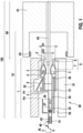
- Figure 1 shows a schematic cross section of a connector arrangement 100.
- the connector arrangement 100 has a connector 50 and a mating connector 60 which can be plugged together with the connector 50.
- the connector 50 has a housing 51 with a contact chamber 52 and a contact element 1 arranged in the contact chamber 52.
- the mating connector 60 has a mating connector housing 61, which is designed like a cup, and a mating contact element 62 arranged in the mating connector housing 61.
- the mating contact element 62 can be designed, for example, in the form of a flat contact blade or a pin or a round contact.
- a radial seal 63 is arranged on a side of the mating connector housing 61 facing the connector 50, which seals when the connectors are plugged together. 50 and mating connector 60 seal the common interior of the connector arrangement 100 against the ingress of dirt and moisture.
- the contact element 1 is suitable for inserting the counter contact element 62 along an insertion direction E.
- the contact element 1 has an insertion opening 2 for inserting the counter contact element 62.
- the contact element 1 also has at least one contact blade 3 for electrically contacting the counter contact element 62. In the cross section of the Fig. 1 two contact blades 3 can be seen. In principle, however, exactly one contact blade 3 or more than two contact blades 3 can be provided.
- the contact element 1 also has a clamping sleeve 4 which can be displaced along the insertion direction E relative to the at least one contact blade 3 between a first position P1 and a second position P2.
- the clamping sleeve 4 and the at least one contact blade 3 are operatively related to one another in such a way that when the clamping sleeve 4 is displaced from the first position P1 to the second position P2, the at least one contact blade 3 is displaced in a radial direction R perpendicular to the insertion direction E, e.g. radially inwards.
- the clamping sleeve 4 has a run-on element 5, which in a projection along the insertion direction E through the insertion opening 2 at least partially covers the insertion opening 2, so that when the counter-contact element 62 is inserted into the contact element 1, the counter-contact element 62 abuts the run-on element 5 (see Figs. 2b , 3b and 3c ) and upon further insertion of the counter contact element 62, the clamping sleeve 4 is displaced by means of the run-up element 5 in the direction of the second position P2.
- the clamping sleeve 4 can be made from a sheet metal, for example.
- the overrun element 5 can be bent radially inwards and protrude into the insertion path of the counter contact element 62 in the manner of a shield.
- the insertion opening 2 is in Fig. 1 through an opening in the housing 51 of the connector 50. If the contact element 1 is considered alone, the insertion opening 2 can be provided by the front end of the at least one contact blade 3 ( Figs. 2a-3c ).
- the clamping sleeve 4 has a first section 7 extending obliquely radially inwards in a front region 6 facing the counter-contact element 62. In the front region, a diameter D of the clamping sleeve 4 decreases from a first diameter D1 to a second diameter D2.
- the first section 7 of the clamping sleeve 4 is followed by a second section 8 which runs essentially parallel to the insertion direction E.
- the diameter D of the clamping sleeve 4 is constant, in the present Fig. 1 this is the second diameter D2.
- the clamping sleeve 4 can, for example, be fixed to the contact element 1 in a captive manner and can be displaced at the same time.
- a link structure can be provided on the contact element 1, for example, which specifies the possible displacement path of the clamping sleeve 4.
- the contact element 1 has Fig. 1 a contact box 35 which surrounds the contact blades 3.
- the contact blades 3 can be cut out of the contact box 35, for example.
- the contact box 35 can also be designed as a box into which the contact blades 3 are inserted or folded into.
- a front contact region 30 viewed along the insertion direction E, is followed by a front contact region 30, a central section 31 and a fastening section 32 for fastening an electrical line or a cable 40.
- the cable 40 has an electrical conductor 42 and insulation 41 which surrounds the conductor 42.
- an insulation crimp 37 and a line crimp 38 are provided here as an example (each shown schematically in dashed lines), although other types of fastening (e.g. soldering, welding, etc.) are also possible.
- the insulation crimp 37 is used to fix the insulation 41 of the cable in the fastening section 32
- the line crimp 38 is used to mechanically fasten the electrical conductor 42 to the contact element 1 and electrically connect it.
- This locking lance 9 can latch into a housing undercut 53 of the housing 51 of the connector 50, so that the contact element 1 is arranged in the contact chamber 52 of the housing 51 in a way that prevents it from being lost - it is then latched into the contact chamber 52.
- an inverse arrangement is also possible, i.e.: an undercut arranged on the contact element 1 in which a housing locking lance arranged on the housing 51 latches.
- the contact box 35 can also be formed by the two contact blades 3. Likewise, the locking lance 9 can be cut out of a contact blade 3.
- An ensemble consisting of the contact element 1 and the mating contact element 62 can also be referred to as a contact arrangement 70, in particular when the mating contact element 62 is inserted into the contact element 1.
- Fig. 1 it is clearly visible that the contact blades 3 are spaced apart from the counter-contact element 62 in the radial direction R as long as the clamping sleeve 4 is in the first position P1.
- Fig. 1 In addition to the insertion direction E, the radial direction R is specified as well as a circumferential direction U surrounding the insertion direction.
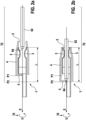
- Figure 2a shows a - simplified - schematic cross-section of a contact element 1 with the clamping sleeve 4 in the first position P1.
- the counter contact element 62 is still in front of the insertion opening 2 or is just passing through it.
- the insertion opening 2 is defined here by the front end of the contact blades 3.
- the counter contact element 62 is thus at the beginning of the plug-in path and thus at the beginning of a defined length L of the plug-in path. This plug-in path is completed here when the counter contact element 62 is completely inserted, i.e. is in a final plug-in position.
- Fig. 2a the contact element 1 is shown without a contact box 35 surrounding the contact blades 3.
- the box formed by the contact blades 3 could also be regarded as a contact box 35.
- Figure 2b shows a schematic cross-section of the contact element 1 from Fig. 2a with the inserted counter contact element 62 in the final plug-in position or final plug-in position and the clamping sleeve 4 in the second position P2.
- the counter contact element 62 with its free end 64 or with its tip has hit the run-up element 5 during the insertion process after approximately 75% of the defined length L of the insertion path.
- the run-up element 5 has dragged or taken the clamping sleeve 4 along the insertion path and thus displaced it relative to the contact blades 3 from the first position P1 to the second position P2.
- the run-up element 5 and the clamping sleeve 4 are operatively connected, e.g. by a relatively rigid coupling or in such a way that the run-up element 5 is only slightly tilted relative to its rest position when the counter contact element 62 hits the run-up element 5.
- the contact blades 3 By moving the clamping sleeve 4 into the second position P2, the contact blades 3 come into contact with an inner wall of the clamping sleeve 4 in its first section 7, in which the diameter D of the clamping sleeve 4 is reduced. As a result, the contact blades 3 are deflected radially inwards and thus pressed against the counter-contact element 62 towards the end of the plug-in path. Shortly before the end of the defined length L of the plug-in path, the diameter D of the clamping sleeve then remains constant in its second section 8, so that the set contact force also remains constant.
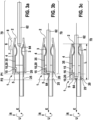
- Figure 3a shows a schematic cross-section of another contact element 1 with the clamping sleeve 4 in the first position P1.
- the locking lance 9 is not shown for reasons of clarity.
- the contact element 1 from Fig. 3a differs from that of Fig. 2a in that a first securing element 10 and a second securing element 10 are formed, arranged or provided on the clamping sleeve 4.
- Figure 3b shows a state in which the counter contact element 61 is inserted into the contact element 1 and is just abutting against the contact element 5 of the contact element 1, with the clamping sleeve 4 still in the first position P1.
- Figure 3c shows the contact element 1 with the inserted counter contact element 61 in the final plug-in position and with the clamping sleeve 4 in the second position P2.
- the first securing element 10 is designed as a type of latching hook. This latching hook engages behind a first undercut 15 of the contact box 35 when or as long as the clamping sleeve 4 is in the first position P1. The first securing element 10 thus prevents the clamping sleeve 4 from being accidentally moved from the first position P1 towards the second position P2 when no counter-contact element 62 is inserted into the contact element 1.
- Fig. 3a It can be seen that the first securing element 10 is operatively connected to the overrun element 5.
- the first securing element 10, which is designed as a latching hook only by way of example, is designed in one piece with the overrun element 5. It projects approximately parallel to the insertion direction E from the overrun element 5 in the direction of the insertion opening 2, the latching hook being formed at the free end of the first securing element 10 and projecting radially outwards.
- the second securing element 20 is intended to prevent a displacement of the clamping sleeve 4 from the second position P2 towards the first position P1 when the clamping sleeve 4 is in the second position P2, see Fig. 3c .
- the second securing element 20 is present twice here.
- Fig. 3a A radially inwardly directed locking hook is formed on the lower part of the clamping sleeve 4 at the end facing away from the insertion opening 2. This can be formed, for example, by bending the clamping sleeve 4 radially inward.
- Fig. 3a In the lower contact blade 3, a second recess 25 is provided in the area of the second position P2, into which this second securing element 20, designed as a latching hook, can engage when the clamping sleeve reaches the second position P2 ( Fig. 3c ).
- the first securing element 10 serves only as an example at the same time as the second securing element 20.
- the contact element 5 can be deflected elastically reversibly in the direction of the insertion direction E by the counter-contact element 61 when it hits in the manner of a spring.
- the overrun element 5 can spring back into its rest position ( Fig. 3c ).
- the locking hook of the first securing element 10 can catch the end of the Fig. 3a upper contact plate 3 and thus prevent unintentional relocation of the clamping sleeve 4 from the second position P2 into the first position P1.
- the first safety element 10 can also have a dual function as the second safety element 20.
- each securing element serves either only as the first securing element 10 or only as the second securing element 20.
- Figure 3b shows that when the counter-contact element 62 abuts against the run-on element 5, the latter is tilted slightly along the insertion direction E. This releases the first securing element 10, which is designed as a latching hook. This is because the latching hook tilts out of the first undercut 15. As a result, the clamping sleeve 4 can be displaced from the first position P1 towards the second position P2 by further moving the counter-contact element 62 along the insertion direction E.
- the clamping sleeve 4 can be moved from the second position P2 to the first position P1, whereby the contact blades 3 are released again from the front area 6 of the clamping sleeve and spring radially outwards. As a result, they are removed or released from the counter-contact element 62 and this can then be removed from the contact element 1 (almost) force-free.
- the clamping sleeve is moved from the second position P2 to the first position P1, the counter-contact element 62 can already be taken in the direction of the insertion opening, e.g. by means of the run-up element 5.
- the contact element 1 or the contact arrangement 70 or the connector 50 or the connector arrangement 100 is or can be intended or suitable or designed for use in motor vehicles or in inverters, motors, control units, batteries, chargers or generators.
- the contact element 1 or the contact arrangement 70 or the Connector 50 or connector assembly 100 is not limited to such applications or uses.
Landscapes
- Connector Housings Or Holding Contact Members (AREA)
- Details Of Connecting Devices For Male And Female Coupling (AREA)
Description
- Die Erfindung betrifft ein Kontaktelement
- Im Gebiet der Steckverbinder, z.B. in der Automobilindustrie, wird kundenseitig eine ergonomische Handhabung von Steckverbindern, insbesondere hinsichtlich der maximalen Betätigungskräfte für den Aufsteckvorgang, erwartet. Die Steckkräfte sollen immer geringer werden. Andererseits erhöhen sich die Polzahlen der Steckverbinder für viele Anwendungen aufgrund höherer Funktionalität, was zu höheren (Direkt)Steckkräften führt. Ein Ansatz, um diesen Zielkonflikt zu lösen, sind Steckverbinder, bei denen die Pins zunächst kraftfrei in die Buchsenkontakte eingeführt werden, und die benötigte Anpresskraft der Kontaktlamellen erst gegen Ende des Einsteckvorgangs oder in einem zweiten Schritt aufgebracht wird. Dadurch kann insbesondere die starke Kraftüberhöhung beim Aufsteckvorgang (Aufschnäbelpeak) vermieden werden.
- Aus der
DE 10 2005 062 889 ist ein Steckverbinder bekannt, der ein Kontaktelement aufweist, wobei am Kontaktelement Kontaktlamellen zur elektrischen Kontaktierung eines in das Kontaktelement einsteckbaren Gegenkontaktelements vorgesehen sind. Hierbei wird die Anpresskraft bzw. Kontaktkraft der Kontaktlamellen auf ein eingestecktes Gegenkontaktelement erst am Ende des Steckwegs des Gegenkontaktelements in den Steckverbinder bzw. in das Kontaktelement erzeugt, indem ein an einem Gehäuse des Steckverbinders angeordnetes Kunststoffelement relativ zum Gehäuse verlagert wird. - Aus der
US 6 368 129 B1 ist ein weiterer Steckverbinder bekannt. - Aus der
EP 0 405 333 A2 ist ein weiterer Steckverbinder bekannt. - Aus der
AT 182 150 B - Die Erfindung geht aus von der Erkenntnis, dass aufgrund beengter Platzverhältnisse und zunehmender Anzahl von stromführenden und/oder signalführenden Leitungen die Abmessungen von Steckverbindern immer geringer werden sollen und hohe Anforderungen an die Kontaktkraft zwischen Kontaktelement und eingestecktem Gegenkontaktelement über Lebensdauer bestehen. Mit anderen Worten: die einmal eingestellte Kontaktkraft soll über Lebensdauer und unter den verschiedenen Betriebsbedingungen möglichst konstant bleiben.
- Gleichzeitig hat sich gezeigt, dass mit der Anzahl der miteinander zu montierenden Teile und der bei der Montage, z.B. bei einem Kabelkonfektionär, durchzuführenden Arbeitsschritte die Kosten steigen und dass das Risiko für Probleme bei der Montage der Teile ansteigt.
- Schließlich hat sich gezeigt, dass eine einfache Wartung oder Reparatur wichtig ist, um die Ausbeute zu steigern und die Kundenzufriedenheit zu verbessern, z.B. soll ein defektes Gegenkontaktelement einfach austauschbar sein.
- Es kann daher ein Bedarf bestehen, ein Kontaktelement, eine Kontaktanordnung aus Kontaktelement und Gegenkontaktelement, einen Steckverbinder bzw. eine Steckverbinderanordnung bereitzustellen, bei der das Einstecken eines Gegenkontaktelements in das Kontaktelement zumindest während eines Großteils des Steckweges bis zur Endsteckstellung (z.B. entlang von mehr als 70% oder mehr als 80% des Steckweges) nur sehr wenig bzw. nahezu keine Steckkraft erfordert, z.B. weniger als 3N pro Kontaktelement-Gegenkontaktelement-Paarung oder sogar weniger als 2N oder weniger als 1N, z.B. 0,05N bis 0,9N.
- Gleichzeitig kann ein Bedarf bestehen, die Kontaktkraft zwischen einer Kontaktlamelle und dem Gegenkontaktelement über Lebensdauer möglichst konstant zu halten, das Kontaktelement und den Steckverbinder möglichst einfach und mit wenigen Teilen zu gestalten: Weiterhin kann ein Bedarf bestehen, den Montagevorgang in wenigen Schritten durchführbar zu gestalten und einfach zu halten sowie das einmal eingesteckte Gegenkontaktelement aus dem Kontaktelement wieder entfernen und durch dasselbe Gegenkontaktelement oder ein neues Gegenkontaktelement ersetzen zu können, wobei wie beim ersten Steckvorgang über einen Großteil des Steckweges bis zur Endsteckstellung nur eine geringe Steckkraft erforderlich sein soll.
- Dieser Bedarf kann durch den Gegenstand der vorliegenden Erfindung gemäß der unabhängigen Ansprüche gedeckt werden. Vorteilhafte Ausführungsformen der vorliegenden Erfindung sind in den abhängigen Ansprüchen beschrieben.
- Gemäß einem ersten Aspekt der Erfindung wird ein Kontaktelement zum Einstecken eines Gegenkontaktelements entlang einer Einsteckrichtung vorgeschlagen.
- Das Kontaktelement weist eine Einstecköffnung zum Einstecken des Gegenkontaktelements auf sowie wenigstens eine Kontaktlamelle zum elektrischen Kontaktieren des Gegenkontaktelements. Weiterhin weist das Kontaktelement eine Spannhülse auf, die entlang der Einsteckrichtung relativ zur wenigstens einen Kontaktlamelle zwischen einer ersten Position und einer zweiten Position verlagerbar ist. Die Spannhülse und die wenigstens eine Kontaktlamelle stehen derart miteinander in Wirkbeziehung, dass beim Verlagern der Spannhülse von der ersten Position in die zweite Position die wenigstens eine Kontaktlamelle in einer zur Einsteckrichtung senkrechten radialen Richtung radial nach innen verlagert wird. Die Spannhülse weist ein Auflaufelement auf, welches in einer Projektion entlang der Einsteckrichtung durch die Einstecköffnung hindurch die Einstecköffnung zumindest teilweise überdeckt, so dass beim Einstecken des Gegenkontaktelements in das Kontaktelement das Gegenkontaktelement an das Auflaufelement anstößt und beim weiteren Einstecken des Gegenkontaktelements die Spannhülse mittels des Auflaufelements in Richtung der zweiten Position verlagert wird.
- Dadurch wird vorteilhaft bewirkt, dass entlang eines Steckweges des Gegenkontaktelements das Gegenkontaktelement zunächst annährend kraftfrei in das Kontaktelement eingeschoben bzw. eingesteckt werden kann. Denn in diesem Zustand können die Kontaktlamellen vom noch nicht vollständig eingesteckten Gegenkontaktelement in einer zur Einsteckrichtung senkrechten, radialen Richtung beabstandet sein oder nur mit einer äußerst geringen Kraftbeaufschlagung am Gegenkontaktelement anliegen.
- Besonders vorteilhaft entfällt bezüglich der Steckkraft ein Aufschnäbelpeak, der durch das Auseinanderdrücken von radial nach innen federnden Kontaktlamellen erforderlich ist und eine initiale Kraftüberhöhung darstellt.
- Durch das an der Spannhülse angeordnete Auflaufelement kann weiterhin vorteilhaft auf ein separates bzw. zusätzlich zu montierendes Element verzichtet werden. Denn durch das Auflaufelement wird die Spannhülse verlagert, so dass gegen Ende des Steckwegs des Gegenkontaktelements die erforderliche Kontaktkraft von der wenigstens einen Kontaktlamelle auf das Gegenkontaktelement mittels der Spannhülse aufgebracht wird.
- Weiterhin vorteilhaft kann auf diese Weise das Zusammenstecken von Kontaktelement und Gegenkontaktelement in einem einzigen Schritt ausgeführt werden. Die Betätigung eines weiteren Elements zur Aufbringung der Kontaktkraft entfällt. Denn das Gegenkontaktelement nimmt die Spannhülse einfach infolge des Steckvorgangs entlang der Einsteckrichtung mit, indem es an das Auflaufelement anstößt und beim weiteren Einsteckvorgang die Spannhülse relativ zu der wenigstens einen Kontaktlamelle verschiebt bzw. verlagert. Das Anstoßen an das Auflaufelement kann z.B. gegen Ende des Steckweges geschehen, z.B. nach 70% oder 80% einer definierten Länge des Steckweges, gerechnet z.B. ab dem Passieren der Einstecköffnung. Dadurch wird außerdem vorteilhaft das Risiko eines Verkantens von Gegenkontaktelement und Kontaktelement verringert.
- Die Spannhülse kann z.B. als Material ein Metall aufweisen oder aus Metall bestehen. Die Spannhülse kann z.B. aus einem gut relaxationsbeständigem Material (z.B. Federstahl) ausgeführt sein. Sie kann z.B. zumindest in einem Abschnitt ringförmig geschlossen ausgebildet sein. Auf diese Weise kann vorteilhaft das Risiko verringert werden, dass die mittels der Spannhülse auf die wenigstens eine Kontaktlamelle übertragene Kontaktkraft durch Alterungsprozesse, z.B. infolge von Materialermüdung, nachlässt. Mit anderen Worten: auf diese Weise kann ein Nachlassen der Federkraft bei Alterung verringert werden.
- Das Kontaktelement kann z.B. mittels eines Befestigungsabschnitts oder eines Crimpabschnitts an ein Kabel bzw. eine Leitung angeschlossen sein, z.B. kraftschlüssig oder stoffschlüssig. Es kann einen Kontaktkasten aufweisen, in dem die wenigstens eine Kontaktlamelle angeordnet ist. Dabei kann die wenigstens eine Kontaktlamelle z.B. aus einem Teil des Kontaktkastens ausgeschnitten bzw. freigeschnitten sein. Der Kontaktkasten kann jedoch auch als eine Art umhüllender Kasten separat von der wenigstens einen Kontaktlamelle ausgebildet sein, die z.B. in ihn eingesteckt und/oder in ihm befestigt ist. Das Kontaktelement kann eine z.B. elastisch reversibel auslenkbare Rastlanze aufweisen, die vom Kontaktelement abragt und dazu ausgebildet ist, das Kontaktelement in einer Kontaktkammer eines Gehäuses eines Steckverbinders zu verrasten. Am Kontaktelement kann z.B. ein Hinterschnitt vorgesehen sein, der von einer Gehäuserastlanze der Kontaktkammer des Steckverbinders hintergriffen wird und so das Kontaktelement in der Kontaktkammer verrastet.
- Es versteht sich, dass das Kontaktelement genau eine Kontaktlamelle aufweisen kann oder mehrere Kontaktlamellen, z.B. zwei, drei, vier oder noch mehr Kontaktlamellen. Diese können z.B. kreisförmig in einer Umlaufrichtung um die Einsteckrichtung herum angeordnet sein. Bei z.B. zwei Kontaktlamellen kann z.B. vorgesehen sein, dass sie sich einander gegenüberliegen, so dass bei eingestecktem Gegenkontaktelement dieses z.B. auf einer Linie zwischen den beiden Kontaktlamellen liegt.
- Die wenigstens eine Kontaktlamelle kann ein Metall, z.B. Kupfer oder Aluminium oder Federstahl aufweisen. Sie kann elastisch reversibel federnd ausgebildet sein. Dabei kann sie z.B. derart ausgebildet sein, dass sie sich in der ersten Position der Spannhülse in einem kraftfreien Zustand befindet und bei einem normalen Einsteckvorgang des Gegenkontaktelements (also einem nicht verkanteten Einstecken) von dem Gegenkontaktelement in radialer Richtung beabstandet ist oder das Gegenkontaktelement lediglich leicht berührt bzw. touchiert. Sie kann weiterhin derart ausgebildet sein, dass sie in der zweiten Position der Spannhülse von der Spannhülse elastisch reversibel nach radial innen, d.h. in Richtung des eingesteckten Gegenkontaktelements gedrückt bzw. verdreht bzw. verschoben bzw. verlagert wird, so dass sie mit dem Gegenkontaktelement in mechanischen Kontakt kommt. Würde die Spannhülse nun wieder in die erste Position verlagert, so würde die wenigstens eine Kontaktlamelle in diesem Beispiel aufgrund ihrer Elastizität wieder in den kraftfreien Zustand zurückfedern, so dass sie vom Gegenkontaktelement wieder beabstandet ist oder dieses lediglich touchiert.
- Die erste Position der Steckhülse kann derart gestaltet sein, dass das einzusteckende Gegenkontaktelement nach z.B. 70% der definierten Länge des Steckweges, z.B. gerechnet ab Passieren der Einstecköffnung, an das Auflaufelement anstößt. Das Auflaufelement kann dabei z.B. quer zur Einsteckrichtung, also in radialer Richtung, von der Spannhülse nach innen abragen. Das Auflaufelement kann derart ausgebildet sein, dass es in den Einsteckweg bzw. Einsteckpfad bzw. Einsteckkanal des Gegenkontaktelements hineinragt, so dass das Gegenkontaktelement z.B. an das Auflaufelement anstoßen kann. Das Auflaufelement kann z.B. durch ein von der Spannhülse nach innen abragendes Blechschild sein. Es kann beispielsweise derart ausgebildet sein, dass es verwindungssteif ist, d.h., dass es durch das Auftreffen des Gegenkontaktelements nicht so stark verbogen wird, dass das Gegenkontaktelement unter dem - dann verbogenen - Auflaufelement hindurchtaucht. Das Auflaufelement kann z.B. einstückig mit der Spannhülse ausgebildet sein. Die Spannhülse und das Auflaufelement können z.B. als einstückiges Stanz-/Biegeteil hergestellt sein. Jedoch ist es auch möglich, dass das Auflaufelement ein zunächst von der Spannhülse separates Teil ist und mit der Spannhülse erst bei der Fertigstellung des Kontaktelements wirkverbunden wird.
- Die zweite Position der Steckhülse kann derart gestaltet sein, dass sie bei einer Endsteckstellung des in das Kontaktelement eingesteckte Gegenkontaktelement erreicht wird bzw. erreicht ist.
- Die Einstecköffnung kann z.B. gebildet sein durch das vorderste Ende der wenigstens einen Kontaktlamelle, die dem Gegenkontaktelement zugewandt ist. Wenn das Kontaktelement einen Kontaktkasten aufweist kann auch eine vordere Öffnung im Kontaktkasten, durch die das Gegenkontaktelement in das Kontaktelement eingesteckt wird, als Einstecköffnung angesehen werden.
- Die Spannhülse kann die Kontaktkraft auf die wenigstens eine Kontaktlamelle aufbringen z.B. durch eine rein lineare Verschiebung der Kontakthülse oder durch eine mit einer linearen Bewegung verknüpften Verkippung der Spannhülse oder durch eine mit einer linearen Bewegung verknüpften Drehung der Spannhülse, um lediglich einige beispielhafte Verlagerungen der Spannhülse darzulegen. Die Spannhülse kann auch ein weiteres Element aufweisen, welches infolge der Verlagerung der Spannhülse z.B. verkippt wird oder sich dreht und dadurch die Kontaktkraft auf die wenigstens eine Kontaktlamelle ausgeübt wird.
- Das Gegenkontaktelement kann z.B. Bestandteil eines Gegensteckverbinders sein, der ein Gegensteckverbindergehäuse aufweist. Das Gegenkontaktelement kann an oder in dem Gegenkontaktelementgehäuse angeordnet sein. Das Gegenkontaktelement kann z.B. als Kontaktmesser oder als Kontaktpin oder als Rundkontakt ausgebildet sein. Es kann z.B. bezüglich seiner Abmessungen in radialer Richtung dazu ausgebildet sein, von der wenigstens einen Kontaktlamelle mit einer definierten Kontaktkraft beaufschlagt zu werden, wenn das Gegenkontaktelement bis zu einer definierten Endsteckstellung in das Kontaktelement eingeschoben ist. Das Gegenkontaktelement kann z.B. als Material ein Metall aufweisen, z.B. Kupfer oder Aluminium.
- Besonders vorteilhaft lässt sich durch das vorgeschlagene Kontaktelement die maximal notwendige Steckkraft auf weniger als 3N, bevorzugt weniger als 2N und ganz besonders bevorzugt auf weniger als 1N pro Kontaktelement-Gegenkontaktelement-Paarung begrenzen, z.B. auf 0,05N bis 0,9N.
- Dadurch, dass die Spannhülse in einem dem Gegenkontaktelement zugewandten vorderen Bereich einen schräg nach radial innen verlaufenden ersten Abschnitt aufweist wird vorteilhaft bewirkt, dass die wenigstens eine Kontaktlamelle nicht plötzlich, sondern über eine gewisse Strecke radial nach innen verlagert wird und dadurch die Kontaktkraft auf das Gegenkontaktelement aufgebracht wird. Durch die Steilheit der Schräge im ersten Abschnitt lässt sich der Anstieg der Steckkraft einstellen.
- Der erste Abschnitt kann z.B. dadurch gestaltet sein, dass sich im ersten Abschnitt der Durchmesser der Spannhülse verringert.
- Dadurch, dass sich - entgegen der Einsteckrichtung betrachtet - an den ersten Abschnitt der Spannhülse ein zweiter Abschnitt anschließt, der parallel zur Einsteckrichtung verläuft, wird vorteilhaft bewirkt, dass auch bei Herstellungstoleranzen z.B. in der Länge der Spannhülse oder der Kontaktlamellen oder eines Kontaktkastens, am Ende des Steckweges stets eine definierte Kontaktkraft auf die wenigstens eine Kontaktlamelle aufgebracht ist bzw. wird. Denn der horizontale zweite Abschnitt kann derartige Längentoleranzen oder auch eine Toleranz der definierten Länge des Steckweges bzw. Einsteckweges des Gegenkontaktelements ausgleichen.
- Beispielsweise kann im zweiten Abschnitt der Durchmesser der Spannhülse konstant ausgebildet sein.
- Erfindungsgemäß ist an der Spannhülse ein erstes Sicherungselement vorgesehen, welches ein Verlagern der Spannhülse von der ersten Position in Richtung der zweiten Position verhindert, wenn kein Gegenkontaktelement in das Kontaktelement eingesteckt ist. Dadurch wird vorteilhaft bewirkt, dass die Spannhülse sich nicht unbeabsichtigt verschiebt und so ein kraftfreies Einstecken des Gegenkontaktelements erschwert oder verhindert ist. Beispielsweise kann das erste Sicherungselement als eine Art Transportsicherung beim Transport des Kontaktelements dienen.
- Lediglich beispielhaft kann das erste Sicherungselement manuell, also unabhängig vom Gegenkontaktelement, betätigbar sein, bevor das Gegenkontaktelement in das Kontaktelement eingesetzt bzw. eingesteckt wird. Auf diese Weise kann die Sicherung entriegelt werden und das Verschieben der Spannhülse von der ersten in die zweite Position ermöglicht werden.
- Dadurch, dass das erste Sicherungselement mit dem Auflaufelement wirkverbunden ist kann eine besonders zuverlässige und automatische Funktion des ersten Sicherungselements bewirkt werden. Denn so kann z.B. beim Auftreffen des Gegenkontaktelements auf das Auflaufelement automatisch das erste Sicherungselement die Blockade des Verlagerns der Spannhülse von der ersten Position in die zweite Position freigeben.
- Lediglich beispielhaft kann das erste Sicherungselement als eine Art Rasthaken ausgebildet sein, der mit dem Auflaufelement wirkverbunden ist und in der ersten Position der Spannhülse einen ersten Hinterschnitt des Kontaktelements bzw. des Kontaktkastens bzw. der Kontaktlamelle hintergreift. Beim Anstoßen des Gegenkontaktelements an das Auflaufelement kann dieser Rasthaken dann z.B. durch eine leichte Verkippung des Auflaufelements aus dem ersten Hinterschnitt herausrutschen und so die Verlagerung der Spannhülse in Richtung der zweiten Position ermöglichen.
- Es versteht sich, dass das erste Sicherungselement auch als eine Aussparung ausgebildet sein kann, in welche ein Rasthaken eingreift, der am Kontaktelement bzw. am Kontaktkasten bzw. an der Kontaktlamelle vorgesehen ist.
- Dadurch, dass an der Spannhülse ein zweites Sicherungselement vorgesehen ist, welches ein Verlagern der Spannhülse von der zweiten Position in Richtung der ersten Position verhindert, wenn sich die Spannhülse in der zweiten Position befindet wird vorteilhaft bewirkt, dass die einmal mittels der Spannhülse aufgebrachte Kontaktkraft nicht durch ein unbeabsichtigtes Verschieben der Kontakthülse wieder verringert wird. Durch das zweite Sicherungselement wird selbst bei verbogenem oder beschädigtem oder verloren gegangenen Auflaufelement ein unbeabsichtigtes Verschieben der Spannhülse unterbunden. Es versteht sich, dass das zweite Sicherungselement derart ausgebildet sein kann, dass es z.B. durch ein Entriegelungswerkzeug oder einen anderen von außen betätigbaren Mechanismus wieder entriegelt werden kann, dass dann also die Spannhülse wieder von der zweiten Position in Richtung der ersten Position verlagerbar ist.
- Lediglich beispielhaft kann das zweite Sicherungselement als vom ersten Sicherungselement separates Element ausgebildet sein. Es kann jedoch auch vorgesehen sein, dass das erste Sicherungselement die Funktion des zweiten Sicherungselements auch erfüllt und deshalb gleichzeitig ein erstes und zweites Sicherungselement darstellt. Das zweite Sicherungselement kann z.B. als eine Art Rasthaken ausgebildet sein, welcher einen zweiten Hinterschnitt hintergreifen kann, der an dem Kontaktelement bzw. am Kontaktkasten bzw. an der Kontaktlamelle ausgebildet ist.
- In einer Ausführungsform kann vorgesehen sein, dass am Kontaktelement ein Hinterschnitt vorgesehen ist zur Verrastung des Kontaktelements in einer Kontaktkammer eines Steckverbinders. Dadurch kann vorteilhaft besonders einfach eine definierte Länge des Steckwegs bzw. eine definierte Stecklänge bzw. ein definierter Steckweg für das Gegenkontaktelement eingestellt werden.
- Alternativ oder zusätzlich kann vorgesehen sein, dass am Kontaktelement eine, insbesondere elastisch reversibel auslenkbare, Rastlanze vorgesehen ist zur Verrastung des Kontaktelements in einer Kontaktkammer eines Steckverbinders. Dadurch kann vorteilhaft besonders einfach ein definierter Steckweg bzw. eine definierte Länge des Steckwegs für das Gegenkontaktelement eingestellt werden.
- Gemäß einem zweiten Aspekt der Erfindung ist eine Kontaktanordnung vorgesehen. Die Kontaktanordnung umfasst ein Kontaktelement wie oben beschrieben bzw. weist dieses auf. Die Kontaktanordnung umfasst weiterhin ein Gegenkontaktelement, welches entlang der Einsteckrichtung in das Kontaktelement eingesteckt ist. Dadurch wird vorteilhaft eine Kontaktanordnung geschaffen, die besonders geringe Steckkräfte benötigt, wenige Teile aufweist und mit wenigen Arbeitsschritten montierbar ist. Weiterhin vorteilhaft kann die Kontaktanordnung einfach gewartet werden.
- Dadurch, dass die wenigstens eine Kontaktlamelle das Gegenkontaktelement zumindest solange nicht berührt, solange das Gegenkontaktelement nicht an das Auflaufelement anstößt wird vorteilhaft eine besonders geringe Steckkraft für das Zusammenstecken der Kontaktanordnung bewirkt.
- Dabei kann der Zustand des Nicht-Berührens z.B. zumindest dann realisiert sein, wenn das Gegenkontaktelement unverkantet, d.h. entlang der Einsteckrichtung, in das Kontaktelement eingesteckt wird.
- Dadurch, dass die wenigstens eine Kontaktlamelle am Gegenkontaktelement mit einer definierten Kraft quer zur Einsteckrichtung anliegt, wenn sich die Spannhülse in der zweiten Position befindet wird vorteilhaft eine elektrische Schnittstelle mit einem reproduzierbaren elektrischen Verhalten, z.B. einem reproduzierbaren elektrischen Übergangswiderstand realisiert. Dies erhöht vorteilhaft die Zuverlässigkeit und die Fehlertoleranz von elektrischen Komponenten, die mittels der Kontaktanordnung miteinander verbunden sind.
- Gemäß einem weiteren Aspekt der Erfindung wird ein Steckverbinder vorgeschlagen. Der Steckverbinder weist ein Gehäuse mit einer Kontaktkammer auf. Der Steckverbinder weist weiterhin ein in der Kontaktkammer angeordnetes Kontaktelement wie oben beschrieben auf. Dadurch wird vorteilhaft ein Steckverbinder bereitgestellt, der mit nur geringer Stecckraft und mit wenigen Arbeitsschritten mit einem Gegensteckverbinder zusammensteckbar ist, wenige Teile aufweist, kostengünstig herstellbar ist und einfach zu warten ist.
- Das Kontaktelement kann z.B. in der Kontaktkammer verrastet sein. Dadurch kann vorteilhaft eine definierte Länge des Steckwegs bzw. ein definierter Steckweg für das Gegenkontaktelement eingestellt werden, wodurch wiederum vorteilhaft reproduzierbar und zuverlässig eine definierte Kontaktkraft am Ende des Steckwegs bewirkt werden kann.
- Gemäß einem weiteren Aspekt der Erfindung wird eine Steckverbinderanordnung vorgeschlagen. Die Steckverbinderanordnung weist einen Steckverbinder wie oben beschrieben auf. Die Steckverbinderanordnung weist weiterhin einen Gegensteckverbinder auf. Der Gegensteckverbinder umfasst ein Gegensteckverbindergehäuse und ein Gegenkontaktelement. Dabei ist im vollständig zusammengesteckten Zustand von Steckverbinder und Gegensteckverbinder die Spannhülse mittels des Gegenkontaktelements in die zweite Position verlagert. Dadurch kann vorteilhaft eine Steckverbinderanordnung bereitgestellt werden, die ein Zusammenstecken ohne Aufschnäbel-Kraftpeak ermöglicht, mit wenigen Teilen und Montageschritten auskommt und gut zu warten bzw. zu reparieren ist.
- Die wenigstens eine Kontaktlamelle kann am Gegenkontaktelement beispielsweise mit einer definierten Kraft quer zur Einsteckrichtung anliegen. Dadurch kann vorteilhaft eine Steckverbinderanordnung mit besonders gut reproduzierbaren elektrischen Eigenschaften bereitgestellt werden.
- Weitere Merkmale und Vorteile der vorliegenden Erfindung werden dem Fachmann aus der nachfolgenden Beschreibung beispielhafter Ausführungsformen, die jedoch nicht als die Erfindung beschränkend auszulegen sind, unter Bezugnahme auf die beigelegten Zeichnungen ersichtlich.
- Es zeigen
- Fig. 1:
- einen schematischen Querschnitt einer Steckverbinderanordnung;
- Fig. 2a:
- einen schematischen Querschnitt eines Kontaktelements mit einer Spannhülse in der ersten Position;
- Fig. 2b:
- einen schematischen Querschnitt des Kontaktelements aus
Fig. 2a mit eingestecktem Gegenkontaktelement in der Endsteckstellung und der Spannhülse in der zweiten Position; - Fig. 3a:
- einen schematischen Querschnitt eines weiteren Kontaktelements mit einer Spannhülse in der ersten Position;
- Fig. 3b:
- einen schematischen Querschnitt des Kontaktelements aus
Fig. 3a , bei dem ein Gegenkontaktelement eingesteckt ist und gerade an ein Auflaufelement des Kontaktelements anstößt, wobei sich die Spannhülse noch in der ersten Position befindet; - Fig. 3c:
- einen schematischen Querschnitt des Kontaktelements aus den
Figuren 3a und 3b mit eingestecktem Gegenkontaktelement in der Endsteckstellung und der Spannhülse in der zweiten Position. -
Figur 1 zeigt einen schematischen Querschnitt einer Steckverbinderanordnung 100. Die Steckverbinderanordnung 100 weist einen Steckverbinder 50 auf sowie einen Gegensteckverbinder 60, der mit dem Steckverbinder 50 zusammensteckbar ist. - Der Steckverbinder 50 weist ein Gehäuse 51 mit einer Kontaktkammer 52 auf sowie ein in der Kontaktkammer 52 angeordnetes Kontaktelement 1.
- Der Gegensteckverbinder 60 weist ein Gegensteckverbindergehäuse 61 auf, welches hier becherartig ausgebildet ist, sowie ein im Gegensteckverbindergehäuse 61 angeordnetes Gegenkontaktelement 62. Das Gegenkontaktelement 62 kann z.B. in der Form eines flachen Kontaktmessers oder eines Pins oder eines Rundkontakts ausgebildet sein. An einer dem Steckverbinder 50 zugewandten Seite des Gegensteckverbindergehäuses 61 ist eine Radialdichtung 63 angeordnet, die im zusammengesteckten Zustand von Steckverbinder 50 und Gegensteckverbinder 60 den gemeinsamen Innenraum der Steckverbinderanordnung 100 gegen das Eindringen von Schmutz und Feuchtigkeit abdichtet.
- Das Kontaktelement 1 ist geeignet zum Einstecken des Gegenkontaktelements 62 entlang einer Einsteckrichtung E. Das Kontaktelement 1 weist eine Einstecköffnung 2 zum Einstecken des Gegenkontaktelements 62 auf. Das Kontaktelement 1 weist weiterhin wenigstens eine Kontaktlamelle 3 zum elektrischen Kontaktieren des Gegenkontaktelements 62 auf. Im Querschnitt der
Fig. 1 sind zwei Kontaktlamellen 3 zu erkennen. Grundsätzlich kann jedoch auch genau eine Kontaktlamelle 3 oder es können mehr als zwei Kontaktlamellen 3 vorgesehen sein. Das Kontaktelement 1 weist außerdem eine Spannhülse 4 auf, die entlang der Einsteckrichtung E relativ zur wenigstens einen Kontaktlamelle 3 zwischen einer ersten Position P1 und einer zweiten Position P2 verlagerbar ist. Die Spannhülse 4 und die wenigstens eine Kontaktlamelle 3 stehen derart miteinander in Wirkbeziehung, dass beim Verlagern der Spannhülse 4 von der ersten Position P1 in die zweite Position P2 die wenigstens eine Kontaktlamelle 3 in einer zur Einsteckrichtung E senkrechten radialen Richtung R, z.B. radial nach innen, verlagert wird. Die Spannhülse 4 weist ein Auflaufelement 5 auf, welches in einer Projektion entlang der Einsteckrichtung E durch die Einstecköffnung 2 hindurch die Einstecköffnung 2 zumindest teilweise überdeckt, so dass beim Einstecken des Gegenkontaktelements 62 in das Kontaktelement 1 das Gegenkontaktelement 62 an das Auflaufelement 5 anstößt (sieheFigs. 2b ,3b und 3c ) und beim weiteren Einstecken des Gegenkontaktelements 62 die Spannhülse 4 mittels des Auflaufelements 5 in Richtung der zweiten Position P2 verlagert wird. - Die Spannhülse 4 kann z.B. aus einem Blech gefertigt sein. Das Auflaufelement 5 kann hier z.B. radial nach innen gebogen sein und in der Art eines Schildes in den Einsteckpfad des Gegenkontaktelements 62 ragen.
- Die Einstecköffnung 2 ist in
Fig. 1 durch eine Öffnung im Gehäuse 51 des Steckverbinders 50 gegeben. Wird alleine das Kontaktelement 1 betrachtet, so kann die Einstecköffnung 2 durch das vordere Ende der wenigstens einen Kontaktlamelle 3 gegeben sein (Figs. 2a-3c ). - Die Spannhülse 4 weist in einem dem Gegenkontaktelement 62 zugewandten vorderen Bereich 6 einen schräg nach radial innen verlaufenden ersten Abschnitt 7 auf. In dem vorderen Bereich verringert sich ein Durchmesser D der Spannhülse 4 von einem ersten Durchmesser D1 zu einem zweiten Durchmesser D2.
- Entgegen der Einsteckrichtung E betrachtet schließt sich an den ersten Abschnitt 7 der Spannhülse 4 ein zweiter Abschnitt 8 an, der im Wesentlichen parallel zur Einsteckrichtung E verläuft. In diesem zweiten Abschnitt 8 ist der Durchmesser D der Spannhülse 4 konstant, in der vorliegenden
Fig. 1 ist dies der zweite Durchmesser D2. - Die Spannhülse 4 kann z.B. unverlierbar am Kontaktelement 1 festgelegt und gleichzeitig verlagerbar sein. Dazu kann am Kontaktelement 1 z.B. eine Kulissenstruktur vorgesehen sein, die den möglichen Verlagerungsweg der Spannhülse 4 vorgibt.
- Das Kontaktelement 1 weist in
Fig. 1 einen Kontaktkasten 35 auf, der die Kontaktlamellen 3 umgibt. Die Kontaktlamellen 3 können z.B. aus dem Kontaktkasten 35 freigeschnitten sein. Der Kontaktkasten 35 kann jedoch auch als ein Kasten ausgebildet sein, in den die Kontaktlamellen 3 eingeschoben oder in den sie hineingefaltet sind. An der inFig. 1 unteren Kontaktlamelle 3 schließt sich - entlang der Einsteckrichtung E betrachtet - an einen vorderen Kontaktierbereich 30 ein Mittelabschnitt 31 an und an diesen ein Befestigungsabschnitt 32 zur Befestigung einer elektrischen Leitung bzw. eines Kabels 40. Das Kabel 40 weist einen elektrischen Leiter 42 sowie eine Isolierung 41 auf, die den Leiter 42 umgibt. In dem Befestigungsabschnitt 32 sind hier beispielhaft ein Isolationscrimp 37 und ein Leitungscrimp 38 vorgesehen jeweils schematisch gestrichelt dargestellt), wobei auch andere Befestigungsarten (z.B. löten, schweißen, etc.) möglich sind. Mit dem Isolationscrimp 37 wird die Isolierung 41 des Kabels in dem Befestigungsabschnitt 32 festgelegt, mit dem Leitungscrimp 38 wird der elektrische Leiter 42 an dem Kontaktelement 1 mechanisch befestigt und elektrisch verbunden. - Am Kontaktkasten 35 ist eine schräg nach außen ragende, z.B. elastisch reversibel auslenkbare, Rastlanze 9 angeordnet. Diese Rastlanze 9 kann in einem Gehäusehinterschnitt 53 des Gehäuses 51 des Steckverbinders 50 verrasten, so dass das Kontaktelement 1 verliersicher in der Kontaktkammer 52 des Gehäuses 51 angeordnet ist - es ist dann in der Kontaktkammer 52 verrastet. Es versteht sich, dass auch eine inverse Anordnung möglich ist, d.h.: ein am Kontaktelement 1 angeordneter Hinterschnitt in dem eine am Gehäuse 51 angeordnete Gehäuserastlanze verrastet.
- Es versteht sich, dass der Kontaktkasten 35 auch durch die beiden Kontaktlamellen 3 gebildet werden kann. Gleichfalls kann die Rastlanze 9 aus einer Kontaktlamelle 3 freigeschnitten sein.
- Ein Ensemble, welches aus dem Kontaktelement 1 und dem Gegenkontaktelement 62 besteht kann auch als Kontaktanordnung 70 bezeichnet werden, insbesondere, wenn das Gegenkontaktelement 62 in das Kontaktelement 1 eingesteckt ist.
- Im - in
Fig. 1 nicht dargestellten - vollständig zusammengesteckten Zustand von Steckverbinder 50 und Gegensteckverbinder 60 ist die Spannhülse 4 mittels des Gegenkontaktelements 62 in die zweite Position P2 verlagert. Die wenigstens eine Kontaktlamelle 3 am Gegenkontaktelement 62 kann dann mit einer definierten Kraft quer zur Einsteckrichtung E anliegen. - In
Fig. 1 ist gut zu erkennen, dass die Kontaktlamellen 3 in radialer Richtung R von dem Gegenkontaktelement 62 beabstandet sind, solange sich die Spannhülse 4 in der ersten Position P1 befindet. Dadurch kann das Einstecken des Gegenkontaktelements 61 in das Kontaktelement 1 weitestgehend kraftfrei erfolgen, insbesondere wird keine Kraft benötigt, um die Kontaktlamellen 3 nach außen aufzudrücken. Der sogenannte Aufschnäbel-Kraftpeak, der sonst zu einer hohen initialen Steckkraft führt, entfällt vorteilhaft. - Zur Erleichterung der Orientierung ist in
Fig. 1 neben der Einsteckrichtung E die radiale Richtung R angegeben sowie eine die Einsteckrichtung umlaufende Umlaufrichtung U. -
Figur 2a zeigt einen - vereinfachten - schematischen Querschnitt eines Kontaktelements 1 mit der Spannhülse 4 in der ersten Position P1. Aus Gründen der Übersichtlichkeit ist die Rastlanze 9 hier weggelassen worden. Das Gegenkontaktelement 62 befindet sich noch vor der Einstecköffnung 2 bzw. passiert diese gerade. Die Einstecköffnung 2 ist hier durch das vordere Ende der Kontaktlamellen 3 definiert. Somit befindet sich das Gegenkontaktelement 62 am Beginn des Steckwegs und somit am Anfang einer definierten Länge L des Steckwegs. Dieser Steckweg ist hier beendet, wenn das Gegenkontaktelement 62 vollständig eingesteckt ist, sich also in einer Endsteckposition befindet. - In
Fig. 2a ist das Kontaktelement 1 ohne einen die Kontaktlamellen 3 umgebenden Kontaktkasten 35 dargestellt. Grundsätzlich könnte der von den Kontaktlamellen 3 gebildete Kasten jedoch auch als Kontaktkasten 35 angesehen werden. -
Figur 2b zeigt einen schematischen Querschnitt des Kontaktelements 1 ausFig. 2a mit eingestecktem Gegenkontaktelement 62 in der Endsteckstellung bzw. Endsteckposition und der Spannhülse 4 in der zweiten Position P2. - Es ist gut zu erkennen, dass das Gegenkontaktelement 62 mit seinem freien Ende 64 bzw. mit seiner Spitze beim Einsteckvorgang nach ca. 75% der definierten Länge L des Steckwegs an das Auflaufelement 5 angestoßen ist. Beim weiteren Einstecken hat das Auflaufelement 5 die Spannhülse 4 entlang des Steckwegs mitgeschleppt bzw. mitgenommen und so relativ zu den Kontaktlamellen 3 von der ersten Position P1 in die zweite Position P2 verlagert. Das Auflaufelement 5 und die Spannhülse 4 sind z.B. wirkverbunden, z.B. durch eine relativ starre Kopplung bzw. so, dass das Auflaufelement 5 nur ein wenig verkippt wird relativ zu seiner Ruheposition, wenn das Gegenkontaktelement 62 an das Auflaufelement 5 anstößt.
- Durch die Verlagerung der Spannhülse 4 in die zweite Position P2 stoßen die Kontaktlamellen 3 an eine Innenwandung der Spannhülse 4 in deren ersten Abschnitt7, in dem sich der Durchmesser D der Spannhülse 4 verringert. Dadurch werden die Kontaktlamellen 3 radial nach innen ausgelenkt und so gegen Ende des Steckwegs an das Gegenkontaktelement 62 gepresst. Kurz vor Ende der definierten Länge L des Steckwegs bleibt dann der Durchmesser D der Spannhülse in deren zweiten Abschnitt 8 konstant, so dass die eingestellte Kontaktkraft ebenfalls konstant bleibt.
-
Figur 3a zeigt einen schematischen Querschnitt eines weiteren Kontaktelements 1 mit der Spannhülse 4 in der ersten Position P1. Auch hier ist aus Gründen der Übersichtlichkeit die Rastlanze 9 nicht dargestellt. Das Kontaktelement 1 ausFig. 3a unterscheidet sich von dem ausFig. 2a dadurch, dass an der Spannhülse 4 ein erstes Sicherungselement 10 und ein zweites Sicherungselement 10 ausgebildet bzw. angeordnet bzw. vorgesehen sind. - In
Figur 3b und Figur 3c wird das Kontaktelement 1 ausFig. 3a beim weiteren Einstecken des Gegenkontaktelements 62 entlang verschiedener Abschnitte der definierten Länge L des Steckwegs gezeigt. -
Figur 3b zeigt dabei einen Zustand, in dem das Gegenkontaktelement 61 in das Kontaktelement 1 eingesteckt ist und gerade an das Auflaufelement 5 des Kontaktelements 1 anstößt, wobei sich die Spannhülse 4 noch in der ersten Position P1 befindet. -
Figur 3c zeigt dann das Kontaktelement 1 mit eingestecktem Gegenkontaktelement 61 in der Endsteckstellung und mit der Spannhülse 4 in der zweiten Position P2. - Das erste Sicherungselement 10 ist als eine Art Rasthaken ausgebildet. Dieser Rasthaken hintergreift einen ersten Hinterschnitt 15 des Kontaktkastens 35, wenn bzw. solange sich die Spannhülse 4 in der ersten Position P1 befindet. Dadurch verhindert das erste Sicherungselement 10 ein unbeabsichtigtes Verlagern der Spannhülse 4 von der ersten Position P1 in Richtung der zweiten Position P2, wenn kein Gegenkontaktelement 62 in das Kontaktelement 1 eingesteckt ist. Aus
Fig. 3a ist erkennbar, dass das erste Sicherungselement 10 mit dem Auflaufelement 5 wirkverbunden ist. InFig. 3a ist das lediglich beispielhaft als Rasthaken ausgebildete erste Sicherungselement 10 z.B. einstückig mit dem Auflaufelement 5 ausgebildet. Es ragt ungefähr parallel zur Einsteckrichtung E vom Auflaufelement 5 in Richtung der Einstecköffnung 2 ab, wobei der Rasthaken am freien Ende des ersten Sicherungselements 10 ausgebildet ist und radial nach außen abragt. - Das zweite Sicherungselement 20 ist dazu vorgesehen, ein Verlagern der Spannhülse 4 von der zweiten Position P2 in Richtung der ersten Position P1 zu verhindern, wenn sich die Spannhülse 4 in der zweiten Position P2 befindet, siehe dazu
Fig. 3c . - Das zweite Sicherungselement 20 ist hier doppelt vorhanden. Zunächst ist in
Fig. 3a am unteren Teil der Spannhülse 4 an deren der Einstecköffnung 2 abgewandten Ende ein nach radial innen gerichteter Rasthaken ausgebildet. Dieser kann z.B. durch ein Umknicken der Spannhülse 4 nach radial innen ausgebildet werden. An der inFig. 3a unteren Kontaktlamelle 3 ist komplementär dazu im Bereich der zweiten Position P2 eine zweite Aussparung 25 vorgesehen, in die dieses als Rasthaken ausgebildete zweite Sicherungselement 20 eingreifen kann, wenn die Spannhülse die zweite Position P2 erreicht (Fig. 3c ). - Wie in
Figs. 3a und 3c zu erkennen ist dient in dieser Ausführungsform das erste Sicherungselement 10 lediglich beispielhaft gleichzeitig auch als zweites Sicherungselement 20. Das Auflaufelement 5 kann durch das Gegenkontaktelement 61 beim Anstoßen in der Art einer Feder elastisch reversibel in Richtung der Einsteckrichtung E ausgelenkt worden sein. Sobald das zwischen der inFig. 3a oberen Kontaktlamelle 3 und dem Gegenkontaktelement 62 angeordnete erste Sicherungselement 10 ein der Einstecköffnung 2 abgewandtes Ende der Kontaktlamelle 3 passiert hat und die Krafteinwirkung durch das Gegenkontaktelement 62 nachlässt, kann das Auflaufelement 5 in seine Ruheposition zurückfedern (Fig. 3c ). Auf diese Weise kann der Rasthaken des ersten Sicherungselements 10 das Ende der imFig. 3a oberen Kontaktlamelle 3 hintergreifen und auf diese Weise ein unbeabsichtigtes Zurückverlagern der Spannhülse 4 von der zweiten Position P2 in die erste Position P1 verhindern. Dadurch kann das erste Sicherungselement 10 hier auch gleichzeitig eine Doppelfunktion als zweites Sicherungselement 20 aufweisen. - Es versteht sich, dass es auch Ausführungsformen geben kann, in denen nur ein einziges eine Doppelfunktion aufweisendes Sicherungselement 10, 20 vorgesehen ist. Es kann jedoch auch Ausführungsformen geben, in denen jedes Sicherungselement entweder nur als erstes Sicherungselement 10 oder nur als zweites Sicherungselement 20 dient.
-
Figur 3b zeigt, dass durch das Anstoßen des Gegenkontaktelements 62 an das Auflaufelement 5 dieses ein wenig entlang der Einsteckrichtung E verkippt wird. Dadurch wird das als Rasthaken ausgebildete erste Sicherungselement 10 gelöst. Denn der Rasthaken kippt aus dem ersten Hinterschnitt 15. Infolgedessen kann durch das weitere Bewegen des Gegenkontaktelements 62 entlang der Einsteckrichtung E die Spannhülse 4 von der ersten Position P1 in Richtung der zweiten Position P2 verlagert werden. - Um das Gegenkontaktelement 62 aus dem Kontaktelement 1 zu entfernen, z.B. zu Wartungszwecken, kann die Spannhülse 4 von der zweiten Position P2 in die erste Position P1 verlagert werden, wodurch die Kontaktlamellen 3 von dem vorderen Bereich 6 der Spannhülse wieder freigegeben werden und nach radial außen federn. Dadurch entfernen bzw. lösen sie sich von dem Gegenkontaktelement 62 und dieses kann anschließend (annährend) kraftfrei aus dem Kontaktelement 1 entfernt werden. Beim Verlagern der Spannhülse von der zweiten Position P2 in die erste Position P1 kann das Gegenkontaktelement 62 z.B. bereits mittels des Auflaufelements 5 in Richtung der Einstecköffnung mitgenommen werden.
- Bei Kontaktelementen 1, die ein zweites Sicherungselement 20 aufweisen ist dieses vor der Verlagerung der Spannhülse 4 von der zweiten Position P2 in die erste Position P1 bevorzugt zu entriegeln bzw. zu entsichern. Dies kann z.B. mittels eines Entriegelungswerkzeugs erfolgen, welches z.B. einen Rasthaken, der einen Hinterschnitt hintergreift aus diesem hintergreifenden Zustand herauslöst.
- Abschließend sei angemerkt, dass das Kontaktelement 1 bzw. die Kontaktanordnung 70 bzw. der Steckverbinder 50 bzw. die Steckverbinderanordnung 100 z.B. für die Anwendung bzw. Verwendung in Kraftfahrzeugen bzw. bei Invertern, Motoren, Steuergeräten, Batterien, Ladegeräten oder Generatoren gedacht bzw. geeignet bzw. eingerichtet ist bzw. sein kann. Jedoch ist das Kontaktelement 1 bzw. die Kontaktanordnung 70 bzw. der Steckverbinder 50 bzw. die Steckverbinderanordnung 100 auf derartige Anwendungen bzw. Verwendungen nicht beschränkt.
Claims (11)
- Kontaktelement zum Einstecken eines Gegenkontaktelements (62) entlang einer Einsteckrichtung (E), das Kontaktelement (1) aufweisend:-- eine Einstecköffnung (2) zum Einstecken des Gegenkontaktelements (62);-- wenigstens eine Kontaktlamelle (3) zum elektrischen Kontaktieren des Gegenkontaktelements (62);-- eine Spannhülse (4), die entlang der Einsteckrichtung (E) relativ zur wenigstens einen Kontaktlamelle (3) zwischen einer ersten Position (P1) und einer zweiten Position (P2) verlagerbar ist;wobei die Spannhülse (4) und die wenigstens eine Kontaktlamelle (3) derart miteinander in Wirkbeziehung stehen, dass beim Verlagern der Spannhülse (4) von der ersten Position (P1) in die zweite Position (P2) die wenigstens eine Kontaktlamelle (3) in einer zur Einsteckrichtung (E) senkrechten radialen Richtung (R) radial nach innen verlagert wird;wobei die Spannhülse (4) ein Auflaufelement (5) aufweist, welches in einer Projektion entlang der Einsteckrichtung (E) durch die Einstecköffnung (2) hindurch die Einstecköffnung (2) zumindest teilweise überdeckt, so dass beim Einstecken des Gegenkontaktelements (62) in das Kontaktelement (1) das Gegenkontaktelement (62) an das Auflaufelement (5) anstößt und beim weiteren Einstecken des Gegenkontaktelements (62) die Spannhülse (4) mittels des Auflaufelements (5) in Richtung der zweiten Position (P2) verlagert wird,wobei an der Spannhülse (4) ein erstes Sicherungselement (10) vorgesehen ist, welches ein Verlagern der Spannhülse (4) von der ersten Position (P1) in Richtung der zweiten Position (P2) verhindert, wenn kein Gegenkontaktelement (62) in das Kontaktelement (1) eingesteckt ist.
- Kontaktelement nach Anspruch 1,wobei die Spannhülse (4) in einem dem Gegenkontaktelement (62) zugewandten vorderen Bereich (6) einen schräg nach radial innen verlaufenden ersten Abschnitt (7) aufweist,in dem sich insbesondere der Durchmesser (D) der Spannhülse (4) verringert.
- Kontaktelement nach dem vorherigen Anspruch,wobei sich entgegen der Einsteckrichtung (E) betrachtet an den ersten Abschnitt (7) der Spannhülse (4) ein zweiter Abschnitt (8) anschließt, der parallel zur Einsteckrichtung (E) verläuft,in dem insbesondere der Durchmesser (D) der Spannhülse (4) konstant ist.
- Kontaktelement nach einem der vorherigen Ansprüche,
wobei das erste Sicherungselement (10) mit dem Auflaufelement (5) wirkverbunden ist. - Kontaktelement nach einem der vorherigen Ansprüche,
wobei an der Spannhülse (4) ein zweites Sicherungselement (20) vorgesehen ist, welches ein Verlagern der Spannhülse (4) von der zweiten Position (P2) in Richtung der ersten Position (P1) verhindert, wenn sich die Spannhülse (4) in der zweiten Position (P2) befindet. - Kontaktelement nach einem der vorhergehenden Ansprüche,wobei am Kontaktelement (1) ein Hinterschnitt vorgesehen ist zur Verrastung des Kontaktelements (1) in einer Kontaktkammer (52) eines Steckverbinders (50) und/oderwobei am Kontaktelement (1) eine, insbesondere elastisch reversibel auslenkbare, Rastlanze (9) vorgesehen ist zur Verrastung des Kontaktelements (1) in einer Kontaktkammer (52) eines Steckverbinders (50).
- Kontaktanordnung umfassend:-- ein Kontaktelement (1) nach einem der vorhergehenden Ansprüche;-- ein Gegenkontaktelement (62), welches entlang der Einsteckrichtung (E) in das Kontaktelement (1) eingesteckt ist.
- Kontaktanordnung nach dem vorhergehenden Anspruch,
wobei die wenigstens eine Kontaktlamelle (3) das Gegenkontaktelement (62) zumindest solange nicht berührt, solange das Gegenkontaktelement (62) nicht an das Auflaufelement (5) anstößt, wenn das Gegenkontaktelement (62) entlang der Einsteckrichtung (E) in das Kontaktelement (1) eingesteckt wird. - Kontaktanordnung nach einem der beiden vorhergehenden Ansprüche,
wobei die wenigstens eine Kontaktlamelle (3) am Gegenkontaktelement (62) mit einer definierten Kraft quer zur Einsteckrichtung (E) anliegt, wenn sich die Spannhülse (4) in der zweiten Position (P2) befindet. - Steckverbinder, aufweisend:-- ein Gehäuse (51) mit einer Kontaktkammer (52);-- ein in der Kontaktkammer (52) angeordnetes Kontaktelement (1) nach einem der Ansprüche 1 bis 6, wobei das Kontaktelement (1) insbesondere in der Kontaktkammer (52) verrastet ist.
- Steckverbinderanordnung, aufweisend:-- einen Steckverbinder (50) nach dem vorhergehenden Anspruch;-- einen Gegensteckverbinder (60)-- mit einem Gegensteckverbindergehäuse (61)-- mit einem Gegenkontaktelement (62);wobei im vollständig zusammengesteckten Zustand von Steckverbinder (50) und Gegensteckverbinder (60) die Spannhülse (4) mittels des Gegenkontaktelements (62) in die zweite Position (P2) verlagert ist,wobei insbesondere die wenigstens eine Kontaktlamelle (3) am Gegenkontaktelement (62) mit einer definierten Kraft quer zur Einsteckrichtung (E) anliegt.
Applications Claiming Priority (2)
| Application Number | Priority Date | Filing Date | Title |
|---|---|---|---|
| DE102019210695.1A DE102019210695B3 (de) | 2019-07-19 | 2019-07-19 | Kontaktelement |
| PCT/EP2020/066888 WO2021013442A1 (de) | 2019-07-19 | 2020-06-18 | Kontaktelement |
Publications (2)
| Publication Number | Publication Date |
|---|---|
| EP4000139A1 EP4000139A1 (de) | 2022-05-25 |
| EP4000139B1 true EP4000139B1 (de) | 2024-10-02 |
Family
ID=71108615
Family Applications (1)
| Application Number | Title | Priority Date | Filing Date |
|---|---|---|---|
| EP20733771.8A Active EP4000139B1 (de) | 2019-07-19 | 2020-06-18 | Kontaktelement |
Country Status (6)
| Country | Link |
|---|---|
| US (1) | US12308590B2 (de) |
| EP (1) | EP4000139B1 (de) |
| JP (1) | JP7326580B2 (de) |
| DE (1) | DE102019210695B3 (de) |
| ES (1) | ES3001460T3 (de) |
| WO (1) | WO2021013442A1 (de) |
Families Citing this family (4)
| Publication number | Priority date | Publication date | Assignee | Title |
|---|---|---|---|---|
| DE102019133032A1 (de) | 2019-12-04 | 2021-08-12 | Te Connectivity Germany Gmbh | Elektrische Kleinkraft-Kontakteinrichtung sowie elektrischer Kleinkraft-Verbinder |
| JP7560803B2 (ja) * | 2021-03-17 | 2024-10-03 | 株式会社オートネットワーク技術研究所 | コネクタ |
| DE102022212777A1 (de) * | 2022-11-29 | 2024-05-29 | Robert Bosch Gesellschaft mit beschränkter Haftung | Steckverbinderanordnung und Steckverbinder |
| EP4586414A1 (de) * | 2024-01-11 | 2025-07-16 | ZF CV Systems Global GmbH | Elektrischer hochspannungsverbinder, kontaktanordnung, verbindungskabel und fahrzeug |
Citations (1)
| Publication number | Priority date | Publication date | Assignee | Title |
|---|---|---|---|---|
| EP1764875A1 (de) * | 2005-09-14 | 2007-03-21 | Robert Bosch Gmbh | Elektrischer Steckverbinder mit vorgespannten Kontaktlamellen |
Family Cites Families (13)
| Publication number | Priority date | Publication date | Assignee | Title |
|---|---|---|---|---|
| AT182150B (de) * | 1952-11-11 | 1955-05-25 | Rudolf Bogenschuetz Gmbh Elekt | Anordnung an Messerkontakten von Sicherungen |
| JPS62150875U (de) | 1986-03-17 | 1987-09-24 | ||
| DE8907845U1 (de) * | 1989-06-27 | 1989-08-24 | Siemens AG, 1000 Berlin und 8000 München | Andruckstellverbinder |
| JPH0449488U (de) | 1990-08-30 | 1992-04-27 | ||
| US6368129B1 (en) * | 1999-12-24 | 2002-04-09 | Delta Electronics, Inc. | Electrical connector with outer and inner sleeves |
| US6644995B1 (en) * | 2002-08-05 | 2003-11-11 | Hon Hai Precision Ind. Co., Ltd. | Low insertion force electrical connector |
| DE102005043693A1 (de) * | 2005-09-14 | 2007-03-15 | Robert Bosch Gmbh | Elektrischer Steckverbinder mit einer vorgespannten Kontaktlamelle |
| DE102005062889A1 (de) * | 2005-12-29 | 2007-07-05 | Robert Bosch Gmbh | Elektrische Null-Kraft-Steckvorrichtung |
| DE102012002145A1 (de) * | 2012-02-04 | 2013-08-08 | Kostal Kontakt Systeme Gmbh | Hülsenkontakt für einen elektrischen Nullkraftsteckverbinder |
| DE102012015568B4 (de) * | 2012-08-08 | 2018-12-20 | Auto-Kabel Management Gmbh | Steckverbinder |
| DE102013225513A1 (de) * | 2013-05-29 | 2014-12-04 | Tyco Electronics Amp Gmbh | Anordnung zur elektrischen Kontaktierung und Steckverbindung umfassend eine solche Anordnung, und Verfahren zum Zusammenstecken einer solchen Anordnung mit einer Gegenanordnung |
| JP6372675B1 (ja) * | 2017-12-14 | 2018-08-15 | Smk株式会社 | カードエッジ接続装置 |
| US10454203B2 (en) * | 2018-03-06 | 2019-10-22 | Te Connectivity Corporation | Receptacle connector of an electrical connector system |
-
2019
- 2019-07-19 DE DE102019210695.1A patent/DE102019210695B3/de not_active Expired - Fee Related
-
2020
- 2020-06-18 WO PCT/EP2020/066888 patent/WO2021013442A1/de not_active Ceased
- 2020-06-18 ES ES20733771T patent/ES3001460T3/es active Active
- 2020-06-18 EP EP20733771.8A patent/EP4000139B1/de active Active
- 2020-06-18 JP JP2022503580A patent/JP7326580B2/ja active Active
- 2020-06-18 US US17/625,396 patent/US12308590B2/en active Active
Patent Citations (1)
| Publication number | Priority date | Publication date | Assignee | Title |
|---|---|---|---|---|
| EP1764875A1 (de) * | 2005-09-14 | 2007-03-21 | Robert Bosch Gmbh | Elektrischer Steckverbinder mit vorgespannten Kontaktlamellen |
Also Published As
| Publication number | Publication date |
|---|---|
| WO2021013442A1 (de) | 2021-01-28 |
| US20220271459A1 (en) | 2022-08-25 |
| JP7326580B2 (ja) | 2023-08-15 |
| ES3001460T3 (en) | 2025-03-05 |
| JP2022541300A (ja) | 2022-09-22 |
| EP4000139A1 (de) | 2022-05-25 |
| US12308590B2 (en) | 2025-05-20 |
| DE102019210695B3 (de) | 2020-10-08 |
Similar Documents
| Publication | Publication Date | Title |
|---|---|---|
| EP2690716B1 (de) | Elektrisches Anschlusselement | |
| DE102007004067B4 (de) | Steckverbinder | |
| EP3937313B1 (de) | Elektrischer steckverbinder | |
| DE69709271T2 (de) | Elektrischer Steckverbinder für Kabel, Montage und dazugehörige Methode | |
| EP4066325B1 (de) | Sekundärverriegelungsvorrichtung | |
| EP3259810B1 (de) | Steckverbinder mit dämpfungselement | |
| EP1901402A1 (de) | Solarsteckverbinder mit verbesserten Rastmitteln | |
| DE102019210695B3 (de) | Kontaktelement | |
| EP3895256B1 (de) | Rundsteckverbinder mit verriegelung | |
| EP2559112B1 (de) | Elektrisches steckverbindungselement und steckverbindungsteil mit mehreren steckverbindungselementen | |
| EP2559110B1 (de) | Vorrichtung zum elektrischen verbinden eines kabels, insbesondere steckverbindungsteil mit einem schirmkontaktelement | |
| EP2559105B1 (de) | Vorrichtung zum elektrischen verbinden eines kabels, insbesondere steckverbindungsteil | |
| EP3713018A1 (de) | Elektrischer steckverbinder, sekundärsicherung und verfahren zur montage eines elektrischen steckverbinders | |
| EP2780986B1 (de) | Steckverbindung | |
| DE102018212135A1 (de) | Elektrischer Verbinder | |
| EP1936755B1 (de) | Steckverbindung, bestehend aus einem Stecker sowie einem Kuppler mit einem Kontaktträger und einem Schutzkragen | |
| EP2031707A2 (de) | Elektrisches Steckverbinderelement | |
| EP3288121A1 (de) | Komplett abgedichteter steckverbinder mit verbesserten haltekräften | |
| DE102020110647A1 (de) | Primärverriegelung | |
| EP1641086B1 (de) | Koaxialsteckverbinder | |
| DE102020126541B4 (de) | Elektrischer Stecker und Fixiervorrichtung zur Fixierung eines Kontaktelements in einem Gehäuse des elektrischen Steckers | |
| EP4544644B1 (de) | Steckverbindergehäuseanordnung und steckverbinder | |
| EP2200127B1 (de) | Steckverbinderanordnung | |
| EP1764874B1 (de) | Elektrischer Steckverbinder mit einer vorgespannten Kontaktlamelle | |
| DE202020005530U1 (de) | Primärverriegelung |
Legal Events
| Date | Code | Title | Description |
|---|---|---|---|
| STAA | Information on the status of an ep patent application or granted ep patent |
Free format text: STATUS: UNKNOWN |
|
| STAA | Information on the status of an ep patent application or granted ep patent |
Free format text: STATUS: THE INTERNATIONAL PUBLICATION HAS BEEN MADE |
|
| PUAI | Public reference made under article 153(3) epc to a published international application that has entered the european phase |
Free format text: ORIGINAL CODE: 0009012 |
|
| STAA | Information on the status of an ep patent application or granted ep patent |
Free format text: STATUS: REQUEST FOR EXAMINATION WAS MADE |
|
| 17P | Request for examination filed |
Effective date: 20220221 |
|
| AK | Designated contracting states |
Kind code of ref document: A1 Designated state(s): AL AT BE BG CH CY CZ DE DK EE ES FI FR GB GR HR HU IE IS IT LI LT LU LV MC MK MT NL NO PL PT RO RS SE SI SK SM TR |
|
| DAV | Request for validation of the european patent (deleted) | ||
| DAX | Request for extension of the european patent (deleted) | ||
| GRAP | Despatch of communication of intention to grant a patent |
Free format text: ORIGINAL CODE: EPIDOSNIGR1 |
|
| STAA | Information on the status of an ep patent application or granted ep patent |
Free format text: STATUS: GRANT OF PATENT IS INTENDED |
|
| RIC1 | Information provided on ipc code assigned before grant |
Ipc: H01R 4/50 20060101ALN20240422BHEP Ipc: H01R 13/11 20060101ALI20240422BHEP Ipc: H01R 13/193 20060101AFI20240422BHEP |
|
| INTG | Intention to grant announced |
Effective date: 20240510 |
|
| GRAS | Grant fee paid |
Free format text: ORIGINAL CODE: EPIDOSNIGR3 |
|
| GRAA | (expected) grant |
Free format text: ORIGINAL CODE: 0009210 |
|
| STAA | Information on the status of an ep patent application or granted ep patent |
Free format text: STATUS: THE PATENT HAS BEEN GRANTED |
|
| AK | Designated contracting states |
Kind code of ref document: B1 Designated state(s): AL AT BE BG CH CY CZ DE DK EE ES FI FR GB GR HR HU IE IS IT LI LT LU LV MC MK MT NL NO PL PT RO RS SE SI SK SM TR |
|
| REG | Reference to a national code |
Ref country code: GB Ref legal event code: FG4D Free format text: NOT ENGLISH |
|
| REG | Reference to a national code |
Ref country code: CH Ref legal event code: EP |
|
| REG | Reference to a national code |
Ref country code: DE Ref legal event code: R096 Ref document number: 502020009374 Country of ref document: DE |
|
| REG | Reference to a national code |
Ref country code: IE Ref legal event code: FG4D Free format text: LANGUAGE OF EP DOCUMENT: GERMAN |
|
| REG | Reference to a national code |
Ref country code: LT Ref legal event code: MG9D |
|
| REG | Reference to a national code |
Ref country code: NL Ref legal event code: MP Effective date: 20241002 |
|
| PG25 | Lapsed in a contracting state [announced via postgrant information from national office to epo] |
Ref country code: NL Free format text: LAPSE BECAUSE OF FAILURE TO SUBMIT A TRANSLATION OF THE DESCRIPTION OR TO PAY THE FEE WITHIN THE PRESCRIBED TIME-LIMIT Effective date: 20241002 |
|
| PG25 | Lapsed in a contracting state [announced via postgrant information from national office to epo] |
Ref country code: NL Free format text: LAPSE BECAUSE OF FAILURE TO SUBMIT A TRANSLATION OF THE DESCRIPTION OR TO PAY THE FEE WITHIN THE PRESCRIBED TIME-LIMIT Effective date: 20241002 |
|
| PG25 | Lapsed in a contracting state [announced via postgrant information from national office to epo] |
Ref country code: PT Free format text: LAPSE BECAUSE OF FAILURE TO SUBMIT A TRANSLATION OF THE DESCRIPTION OR TO PAY THE FEE WITHIN THE PRESCRIBED TIME-LIMIT Effective date: 20250203 Ref country code: HR Free format text: LAPSE BECAUSE OF FAILURE TO SUBMIT A TRANSLATION OF THE DESCRIPTION OR TO PAY THE FEE WITHIN THE PRESCRIBED TIME-LIMIT Effective date: 20241002 Ref country code: IS Free format text: LAPSE BECAUSE OF FAILURE TO SUBMIT A TRANSLATION OF THE DESCRIPTION OR TO PAY THE FEE WITHIN THE PRESCRIBED TIME-LIMIT Effective date: 20250202 |
|
| PG25 | Lapsed in a contracting state [announced via postgrant information from national office to epo] |
Ref country code: FI Free format text: LAPSE BECAUSE OF FAILURE TO SUBMIT A TRANSLATION OF THE DESCRIPTION OR TO PAY THE FEE WITHIN THE PRESCRIBED TIME-LIMIT Effective date: 20241002 |
|
| PG25 | Lapsed in a contracting state [announced via postgrant information from national office to epo] |
Ref country code: BG Free format text: LAPSE BECAUSE OF FAILURE TO SUBMIT A TRANSLATION OF THE DESCRIPTION OR TO PAY THE FEE WITHIN THE PRESCRIBED TIME-LIMIT Effective date: 20241002 |
|
| PG25 | Lapsed in a contracting state [announced via postgrant information from national office to epo] |
Ref country code: NO Free format text: LAPSE BECAUSE OF FAILURE TO SUBMIT A TRANSLATION OF THE DESCRIPTION OR TO PAY THE FEE WITHIN THE PRESCRIBED TIME-LIMIT Effective date: 20250102 |
|
| PG25 | Lapsed in a contracting state [announced via postgrant information from national office to epo] |
Ref country code: GR Free format text: LAPSE BECAUSE OF FAILURE TO SUBMIT A TRANSLATION OF THE DESCRIPTION OR TO PAY THE FEE WITHIN THE PRESCRIBED TIME-LIMIT Effective date: 20250103 Ref country code: LV Free format text: LAPSE BECAUSE OF FAILURE TO SUBMIT A TRANSLATION OF THE DESCRIPTION OR TO PAY THE FEE WITHIN THE PRESCRIBED TIME-LIMIT Effective date: 20241002 |
|
| PG25 | Lapsed in a contracting state [announced via postgrant information from national office to epo] |
Ref country code: CZ Free format text: LAPSE BECAUSE OF FAILURE TO SUBMIT A TRANSLATION OF THE DESCRIPTION OR TO PAY THE FEE WITHIN THE PRESCRIBED TIME-LIMIT Effective date: 20241002 Ref country code: PL Free format text: LAPSE BECAUSE OF FAILURE TO SUBMIT A TRANSLATION OF THE DESCRIPTION OR TO PAY THE FEE WITHIN THE PRESCRIBED TIME-LIMIT Effective date: 20241002 |
|
| PG25 | Lapsed in a contracting state [announced via postgrant information from national office to epo] |
Ref country code: RS Free format text: LAPSE BECAUSE OF FAILURE TO SUBMIT A TRANSLATION OF THE DESCRIPTION OR TO PAY THE FEE WITHIN THE PRESCRIBED TIME-LIMIT Effective date: 20250102 |
|
| PG25 | Lapsed in a contracting state [announced via postgrant information from national office to epo] |
Ref country code: SM Free format text: LAPSE BECAUSE OF FAILURE TO SUBMIT A TRANSLATION OF THE DESCRIPTION OR TO PAY THE FEE WITHIN THE PRESCRIBED TIME-LIMIT Effective date: 20241002 |
|
| REG | Reference to a national code |
Ref country code: DE Ref legal event code: R097 Ref document number: 502020009374 Country of ref document: DE |
|
| PG25 | Lapsed in a contracting state [announced via postgrant information from national office to epo] |
Ref country code: DK Free format text: LAPSE BECAUSE OF FAILURE TO SUBMIT A TRANSLATION OF THE DESCRIPTION OR TO PAY THE FEE WITHIN THE PRESCRIBED TIME-LIMIT Effective date: 20241002 |
|
| PGFP | Annual fee paid to national office [announced via postgrant information from national office to epo] |
Ref country code: GB Payment date: 20250620 Year of fee payment: 6 |
|
| PG25 | Lapsed in a contracting state [announced via postgrant information from national office to epo] |
Ref country code: EE Free format text: LAPSE BECAUSE OF FAILURE TO SUBMIT A TRANSLATION OF THE DESCRIPTION OR TO PAY THE FEE WITHIN THE PRESCRIBED TIME-LIMIT Effective date: 20241002 |
|
| PGFP | Annual fee paid to national office [announced via postgrant information from national office to epo] |
Ref country code: FR Payment date: 20250626 Year of fee payment: 6 |
|
| PG25 | Lapsed in a contracting state [announced via postgrant information from national office to epo] |
Ref country code: RO Free format text: LAPSE BECAUSE OF FAILURE TO SUBMIT A TRANSLATION OF THE DESCRIPTION OR TO PAY THE FEE WITHIN THE PRESCRIBED TIME-LIMIT Effective date: 20241002 |
|
| PG25 | Lapsed in a contracting state [announced via postgrant information from national office to epo] |
Ref country code: SK Free format text: LAPSE BECAUSE OF FAILURE TO SUBMIT A TRANSLATION OF THE DESCRIPTION OR TO PAY THE FEE WITHIN THE PRESCRIBED TIME-LIMIT Effective date: 20241002 |
|
| PLBE | No opposition filed within time limit |
Free format text: ORIGINAL CODE: 0009261 |
|
| STAA | Information on the status of an ep patent application or granted ep patent |
Free format text: STATUS: NO OPPOSITION FILED WITHIN TIME LIMIT |
|
| PG25 | Lapsed in a contracting state [announced via postgrant information from national office to epo] |
Ref country code: SE Free format text: LAPSE BECAUSE OF FAILURE TO SUBMIT A TRANSLATION OF THE DESCRIPTION OR TO PAY THE FEE WITHIN THE PRESCRIBED TIME-LIMIT Effective date: 20241002 |
|
| 26N | No opposition filed |
Effective date: 20250703 |
|
| PGFP | Annual fee paid to national office [announced via postgrant information from national office to epo] |
Ref country code: ES Payment date: 20250718 Year of fee payment: 6 |
|
| PGFP | Annual fee paid to national office [announced via postgrant information from national office to epo] |
Ref country code: DE Payment date: 20250814 Year of fee payment: 6 |
|
| PGFP | Annual fee paid to national office [announced via postgrant information from national office to epo] |
Ref country code: IT Payment date: 20250630 Year of fee payment: 6 |
|
| REG | Reference to a national code |
Ref country code: CH Ref legal event code: H13 Free format text: ST27 STATUS EVENT CODE: U-0-0-H10-H13 (AS PROVIDED BY THE NATIONAL OFFICE) Effective date: 20260127 |
|
| PG25 | Lapsed in a contracting state [announced via postgrant information from national office to epo] |
Ref country code: MC Free format text: LAPSE BECAUSE OF FAILURE TO SUBMIT A TRANSLATION OF THE DESCRIPTION OR TO PAY THE FEE WITHIN THE PRESCRIBED TIME-LIMIT Effective date: 20241002 |
|
| PG25 | Lapsed in a contracting state [announced via postgrant information from national office to epo] |
Ref country code: LU Free format text: LAPSE BECAUSE OF NON-PAYMENT OF DUE FEES Effective date: 20250618 |
|
| REG | Reference to a national code |
Ref country code: BE Ref legal event code: MM Effective date: 20250630 |
|
| PG25 | Lapsed in a contracting state [announced via postgrant information from national office to epo] |
Ref country code: IE Free format text: LAPSE BECAUSE OF NON-PAYMENT OF DUE FEES Effective date: 20250618 |
|
| PG25 | Lapsed in a contracting state [announced via postgrant information from national office to epo] |
Ref country code: BE Free format text: LAPSE BECAUSE OF NON-PAYMENT OF DUE FEES Effective date: 20250630 |
|
| PG25 | Lapsed in a contracting state [announced via postgrant information from national office to epo] |
Ref country code: CH Free format text: LAPSE BECAUSE OF NON-PAYMENT OF DUE FEES Effective date: 20250630 |