EP4000149B1 - Dispositif conducteur électrique - Google Patents
Dispositif conducteur électrique Download PDFInfo
- Publication number
- EP4000149B1 EP4000149B1 EP20746896.8A EP20746896A EP4000149B1 EP 4000149 B1 EP4000149 B1 EP 4000149B1 EP 20746896 A EP20746896 A EP 20746896A EP 4000149 B1 EP4000149 B1 EP 4000149B1
- Authority
- EP
- European Patent Office
- Prior art keywords
- yarn
- insulating jacket
- conductor
- section
- conductor assembly
- Prior art date
- Legal status (The legal status is an assumption and is not a legal conclusion. Google has not performed a legal analysis and makes no representation as to the accuracy of the status listed.)
- Active
Links
Images

Classifications
-
- H—ELECTRICITY
- H02—GENERATION; CONVERSION OR DISTRIBUTION OF ELECTRIC POWER
- H02G—INSTALLATION OF ELECTRIC CABLES OR LINES, OR OF COMBINED OPTICAL AND ELECTRIC CABLES OR LINES
- H02G15/00—Cable fittings
- H02G15/02—Cable terminations
- H02G15/06—Cable terminating boxes, frames or other structures
- H02G15/064—Cable terminating boxes, frames or other structures with devices for relieving electrical stress
- H02G15/068—Cable terminating boxes, frames or other structures with devices for relieving electrical stress connected to the cable shield only
-
- H—ELECTRICITY
- H01—ELECTRIC ELEMENTS
- H01B—CABLES; CONDUCTORS; INSULATORS; SELECTION OF MATERIALS FOR THEIR CONDUCTIVE, INSULATING OR DIELECTRIC PROPERTIES
- H01B7/00—Insulated conductors or cables characterised by their form
- H01B7/17—Protection against damage caused by external factors, e.g. sheaths or armouring
- H01B7/18—Protection against damage caused by wear, mechanical force or pressure; Sheaths; Armouring
-
- H—ELECTRICITY
- H05—ELECTRIC TECHNIQUES NOT OTHERWISE PROVIDED FOR
- H05K—PRINTED CIRCUITS; CASINGS OR CONSTRUCTIONAL DETAILS OF ELECTRIC APPARATUS; MANUFACTURE OF ASSEMBLAGES OF ELECTRICAL COMPONENTS
- H05K9/00—Screening of apparatus or components against electric or magnetic fields
- H05K9/0073—Shielding materials
- H05K9/0081—Electromagnetic shielding materials, e.g. EMI, RFI shielding
- H05K9/009—Electromagnetic shielding materials, e.g. EMI, RFI shielding comprising electro-conductive fibres, e.g. metal fibres, carbon fibres, metallised textile fibres, electro-conductive mesh, woven, non-woven mat, fleece, cross-linked
-
- H—ELECTRICITY
- H01—ELECTRIC ELEMENTS
- H01B—CABLES; CONDUCTORS; INSULATORS; SELECTION OF MATERIALS FOR THEIR CONDUCTIVE, INSULATING OR DIELECTRIC PROPERTIES
- H01B1/00—Conductors or conductive bodies characterised by the conductive materials; Selection of materials as conductors
- H01B1/20—Conductive material dispersed in non-conductive organic material
-
- H—ELECTRICITY
- H01—ELECTRIC ELEMENTS
- H01B—CABLES; CONDUCTORS; INSULATORS; SELECTION OF MATERIALS FOR THEIR CONDUCTIVE, INSULATING OR DIELECTRIC PROPERTIES
- H01B13/00—Apparatus or processes specially adapted for manufacturing conductors or cables
- H01B13/22—Sheathing; Armouring; Screening; Applying other protective layers
-
- H—ELECTRICITY
- H01—ELECTRIC ELEMENTS
- H01B—CABLES; CONDUCTORS; INSULATORS; SELECTION OF MATERIALS FOR THEIR CONDUCTIVE, INSULATING OR DIELECTRIC PROPERTIES
- H01B13/00—Apparatus or processes specially adapted for manufacturing conductors or cables
- H01B13/22—Sheathing; Armouring; Screening; Applying other protective layers
- H01B13/26—Sheathing; Armouring; Screening; Applying other protective layers by winding, braiding or longitudinal lapping
-
- H—ELECTRICITY
- H01—ELECTRIC ELEMENTS
- H01B—CABLES; CONDUCTORS; INSULATORS; SELECTION OF MATERIALS FOR THEIR CONDUCTIVE, INSULATING OR DIELECTRIC PROPERTIES
- H01B17/00—Insulators or insulating bodies characterised by their form
- H01B17/56—Insulating bodies
- H01B17/58—Tubes, sleeves, beads, or bobbins through which the conductor passes
-
- H—ELECTRICITY
- H01—ELECTRIC ELEMENTS
- H01B—CABLES; CONDUCTORS; INSULATORS; SELECTION OF MATERIALS FOR THEIR CONDUCTIVE, INSULATING OR DIELECTRIC PROPERTIES
- H01B7/00—Insulated conductors or cables characterised by their form
- H01B7/0009—Details relating to the conductive cores
-
- H—ELECTRICITY
- H01—ELECTRIC ELEMENTS
- H01B—CABLES; CONDUCTORS; INSULATORS; SELECTION OF MATERIALS FOR THEIR CONDUCTIVE, INSULATING OR DIELECTRIC PROPERTIES
- H01B7/00—Insulated conductors or cables characterised by their form
- H01B7/02—Disposition of insulation
-
- H—ELECTRICITY
- H01—ELECTRIC ELEMENTS
- H01B—CABLES; CONDUCTORS; INSULATORS; SELECTION OF MATERIALS FOR THEIR CONDUCTIVE, INSULATING OR DIELECTRIC PROPERTIES
- H01B7/00—Insulated conductors or cables characterised by their form
- H01B7/17—Protection against damage caused by external factors, e.g. sheaths or armouring
- H01B7/28—Protection against damage caused by moisture, corrosion, chemical attack or weather
- H01B7/2806—Protection against damage caused by corrosion
-
- H—ELECTRICITY
- H02—GENERATION; CONVERSION OR DISTRIBUTION OF ELECTRIC POWER
- H02G—INSTALLATION OF ELECTRIC CABLES OR LINES, OR OF COMBINED OPTICAL AND ELECTRIC CABLES OR LINES
- H02G15/00—Cable fittings
- H02G15/08—Cable junctions
- H02G15/18—Cable junctions protected by sleeves, e.g. for communication cable
- H02G15/184—Cable junctions protected by sleeves, e.g. for communication cable with devices for relieving electrical stress
-
- H—ELECTRICITY
- H05—ELECTRIC TECHNIQUES NOT OTHERWISE PROVIDED FOR
- H05K—PRINTED CIRCUITS; CASINGS OR CONSTRUCTIONAL DETAILS OF ELECTRIC APPARATUS; MANUFACTURE OF ASSEMBLAGES OF ELECTRICAL COMPONENTS
- H05K9/00—Screening of apparatus or components against electric or magnetic fields
- H05K9/0073—Shielding materials
- H05K9/0098—Shielding materials for shielding electrical cables
-
- H—ELECTRICITY
- H01—ELECTRIC ELEMENTS
- H01B—CABLES; CONDUCTORS; INSULATORS; SELECTION OF MATERIALS FOR THEIR CONDUCTIVE, INSULATING OR DIELECTRIC PROPERTIES
- H01B17/00—Insulators or insulating bodies characterised by their form
- H01B17/56—Insulating bodies
- H01B17/60—Composite insulating bodies
Definitions
- the invention relates to an electrical conductor arrangement comprising an electrical conductor, an electrically insulating sheath arranged around at least one conductor section of the conductor, and an electrically conductive sheath arranged around an insulating sheath section of the insulating sheath.
- Such conductor arrangements are used in and/or on many electrical devices, for example, in electrical feedthroughs through housing openings or on cables, where the electrically conductive sheath of a conductor arrangement serves, for example, to shield against electric fields.
- a particular weak point of such a conductor arrangement is the area where the sheath ends around the insulating jacket. In this area, high field strengths of an electric field at the end of the sheath, which acts as an electrical electrode, can lead to significant discharges (“sparks") on the surface of the insulating jacket, which can damage or destroy the insulating jacket in a short time. This effect is further amplified if the end of the sheath has sharp edges, because small radii of an edge of the sheath lead to particularly high electric field strengths in the area surrounding the edge.
- field control Measures that influence local electric field strengths are referred to as field control.
- Elements for field control are referred to as field control elements.
- different measures are used. For example, it may be sufficient to make the radii of an electrode large enough to keep the field strength at the interface below the electrical strength of the insulating sheath. This type of field control is referred to as geometric field control.
- weakly conductive coatings in the form of varnishes, tapes, or filled plastics can be applied to the surface of the insulating sheath as field control elements.
- the electric field drives a current through these materials, which, together with their resistance, leads to a voltage drop.
- This voltage drop defines the potential along the surface.
- This type of field control is called resistive field control.
- the field strength for alternating voltage is not constant along such a system, since part of the current flows capacitively via the insulating sheath to the conductor of the conductor arrangement. As a result, the voltage drop is lower further away from the sheath. This can be counteracted by reducing the resistance along the length of the field control element.
- Another possibility is to use materials whose conductivity is strongly dependent on the applied field strength. At particularly exposed areas, such materials become more conductive, further reducing the field strength. This type of field control is called nonlinear field control.
- refractive materials with a high relative permittivity can be used for AC systems. These materials "break” the electric field at their interface with the insulation, thus pushing it away from the electrode edge. This type of field control is called refractive field control.
- a termination for a plastic-insulated power cable is known. This includes a field control cone with a continuous conductor wire embedded in its sheath.
- From the DE 17 77 892 U is a device for the production of terminations for high-voltage cables, high-voltage bushings for transformers, converters, or the like, made of castable, curable, or self-curing insulating compounds with conductive inserts for potential control.
- Concentric rings made of conductive materials, particularly metal, can be inserted into the mold before the compound is poured. The rings can be secured in the mold by webs or threads made of an insulating material with chemical and physical properties corresponding to the casting compound.
- the invention is based on the object of providing an electrical conductor arrangement of the type described above with a simple, to specify precise field control that can be adapted to the respective requirements, in particular for electrical bushings and cables.
- an electrical conductor arrangement having the features of claim 1
- An electrical conductor arrangement comprises an electrical conductor, an electrically insulating sheath arranged around at least one conductor section of the conductor, an electrically conductive sheath arranged around a first insulating sheath section of the insulating sheath, and an electrically conductive yarn wound around a second insulating sheath section of the insulating sheath adjacent to the first insulating sheath section for electrical field control.
- a winding device is used, in particular, for winding.
- a rotational movement is performed for winding. For example, the conductor arrangement is rotated with the insulating sheath.
- the yarn (the electrically conductive yarn) can be wound directly onto the insulating sheath.
- the yarn (the electrically conductive yarn) is or will therefore be wound directly onto the insulating sheath.
- An electrical conductor arrangement thus comprises an electrically conductive yarn for field control.
- the yarn is wound around an insulating sheath section of an insulating sheath, which surrounds an adjacent insulating sheath section between a conductor and an electrically conductive sheath of the conductor arrangement.
- the yarn is used as a field control element for an electric field at the end of the electrically conductive sheath.
- a yarn end portion of the yarn is connected to a sheath end portion of the sheath, for example, by gluing. This advantageously fixes a yarn end portion of the yarn near the sheath end portion of the sheath, and the yarn is electrically coupled to the sheath galvanically and/or capacitively.
- the yarn is wound helically around the second insulating sheath section.
- the helical winding of the yarn can have different pitches.
- the pitch of the helical winding and its variation along the course of the winding allow the electrical resistance of the winding and its local variation in a direction parallel to the conductor to be flexibly adapted to the respective field control requirements.
- the yarn has a lower specific electrical conductivity than the sheath.
- the wound yarn has an electrical resistance in the range between 1 M ⁇ /m and 100 M ⁇ /m.
- the yarn is made of a polyamide fiber which is surrounded by an electrically conductive coated with a carbon-containing material, or made of a fiber mixture comprising at least one polyamide fiber and one electrically conductive carbon fiber, or of a metallic fiber.
- the yarn is surrounded by a protective layer or protective sheath.
- a protective layer or protective sheath advantageously protects the yarn against mechanical and/or chemical damage.
- the dielectric strength of the system consisting of the yarn and the protective layer or protective sheath can be increased.
- the yarn is fixed to the second insulating sheath section by a hardening or hardenable resin.
- a hardening or hardenable resin advantageously stabilizes the yarn and protects it against local and global mechanical displacements.
- the local pitches of the winding can be fixed.
- a curing or curable resin is applied to the second insulating sheath section to fix the yarn to the second insulating sheath section, and the yarn is wound around the second insulating sheath section before the resin on the resin has completely cured.
- An electrical feedthrough according to the invention through a housing opening of a housing of an electrical device has a conductor arrangement according to the invention, the Sheath is electrically connected to the housing and is guided through the housing opening with the conductor and the insulating sheath.
- a cable according to the invention has a conductor arrangement according to the invention.
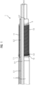
- FIG 1 shows an embodiment of an electrical conductor arrangement 1 according to the invention in a partially sectioned view, wherein the upper part of the FIG 1
- the conductor assembly 1 is shown in section.
- the conductor assembly 1 comprises an electrical conductor 3, an electrically insulating insulating jacket 5, an electrically conductive sheath 7, an electrically conductive yarn 9 for electric field control, a resin layer 11, and a protective layer 13.
- the insulating jacket 5 is arranged around a conductor section 3.1 of the conductor 3.
- the sheath 7 is arranged around a first insulating jacket section 5.1 of the insulating jacket 5.
- the resin layer 11 is applied to an outer surface of a second insulating jacket section 5.2 of the insulating jacket 5, which section is adjacent to the first insulating jacket section 5.1.
- the yarn 9 is wound helically around the second insulating jacket section 5.2 on the resin layer 11.
- the resin layer 11 fixes the yarn 9 to the second insulating jacket section 5.2.
- a yarn end section 9.1 of the yarn 9 is electrically conductively connected to a sheath end section 7.1 of the sheath 7 and is firmly fixed to the sheath end section 7.1 by an adhesive 15.
- the sheath end section 7.1 has an outer diameter that tapers conically towards the second insulating jacket section 5.2.
- the protective layer 13 is arranged around the yarn 9 and the resin layer 11.
- the protective layer 13 is shown transparent, but
- the conductor 3 is made of copper, for example.
- the insulating sheath 5 is made of polyetheretherketone (PEEK), cross-linked polyethylene (VPE), polyvinyl chloride (PVC) or a comparable polymer, oil-paper, ceramic, silicone, resin-impregnated mica tapes, or synthetic resin.
- the sheath 7 is made of stainless steel, for example.
- the yarn 9 is made of a polyamide fiber encased in an electrically conductive carbon-containing material, a fiber mixture comprising at least one polyamide fiber and one electrically conductive carbon fiber, or a thin metallic fiber.
- the resin layer 11 is made of a curing or hardening resin, for example, epoxy resin.
- the protective layer 13 is also made of a curing or hardening resin, for example, in particular of the same resin as the resin layer 11.
- the yarn 9 has a lower specific electrical conductivity than the sheath 7.
- the wound Yarn 9 has an electrical resistance in the range between 1 M ⁇ /m and 100 M ⁇ /m.
- a base body is first produced, comprising the conductor 3, the insulating sheath 5, and the sheath 7.
- Resin for the resin layer 11 is then applied to the second insulating sheath section 5.2.
- the yarn 9 is then wound around the sheath end section 7.1 and the second insulating sheath section 5.2, pressed against the resin, and bonded to the sheath end section 7.1 by the adhesive 15.
- material for the protective layer 13 is applied to the yarn 9 and the resin layer 11.
- FIG 2 shows a partially sectioned illustration of an embodiment of an electrical feedthrough 17 according to the invention through a housing opening 19.1 of an electrically conductive housing 19 of an electrical device.
- the electrical device is, for example, an electrical machine such as a motor, a generator or a transformer, or an electrical switching device such as a circuit breaker or a disconnector.
- the feedthrough 17 comprises a FIG 1 formed conductor arrangement 1 and a seal 21.
- the housing 19 and the seal 21 are shown in section, the conductor arrangement 1 is as in Figure 1 shown partially in section.
- the insulating sheath section 5.2 of the conductor arrangement 1 is arranged within the housing 19.
- the sleeve 7 protrudes from the housing opening 19.1.
- the seal 21 runs annularly around the sleeve 7, connects the sleeve 7 in an electrically conductive manner to the housing 19, and seals the housing opening 19.1.
- the sleeve 7 is made of a material containing graphite.
- the conductor 3 is connected or connectable to a current path of the electrical equipment (in the case that the electrical equipment is an electrical machine, the conductor 3 is connected, for example, to a winding of the machine; in the case that the electrical equipment is an electrical switching device, the conductor 3 for example, connected to a switching contact of the switching device).
- the shell 7 and the housing 19 are connected, for example, to earth potential.
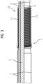
- FIG 3 shows analogous to FIG 1 a partially sectioned view of an embodiment of a cable 23 according to the invention.
- the cable 23 comprises a FIG 1 formed conductor arrangement 1, which forms a first cable end of the cable 23, wherein the insulating sheath 5 extends around the conductor 3 to a (not shown) second cable end of the cable 23.
- the second cable end can be formed like the first cable end.
- the Figures 1 to 3 The exemplary embodiments of conductor arrangements 1 shown can be modified in various ways.
- the helical winding of the yarn 9 can have locally different pitches in order to change the electrical resistance of the winding along its course and to adapt it to the requirements of field control.
- a protective sheath instead of a protective layer 13, a protective sheath can be provided which envelops the yarn 9 and the resin layer 11.
- Further exemplary embodiments of a conductor arrangement 1 according to the invention have no resin layer 11 and/or no protective layer 13 at all.
- the yarn 9 is not electrically connected to the sheath 7, but is only capacitively coupled to the sheath 7.
Landscapes
- Engineering & Computer Science (AREA)
- Manufacturing & Machinery (AREA)
- Microelectronics & Electronic Packaging (AREA)
- Physics & Mathematics (AREA)
- Textile Engineering (AREA)
- Electromagnetism (AREA)
- Chemical & Material Sciences (AREA)
- Dispersion Chemistry (AREA)
- Spectroscopy & Molecular Physics (AREA)
- Insulators (AREA)
- Insulated Conductors (AREA)
- Insulating Bodies (AREA)
- Communication Cables (AREA)
Claims (12)
- Dispositif (1) conducteur électrique, comprenant- un conducteur (3) électrique,- au moins une chemise (5) isolante électriquement disposée autour d'un tronçon (3.1) du conducteur (3),- une gaine (7) conductrice de l'électricité, qui est disposée autour d'un premier tronçon (5.1) de la chemise (5) isolante,caractérisé en ce qu'un fil (9) conducteur de l'électricité est, pour la commande du champ électrique, enroulé autour d'un deuxième tronçon (5.2), contigu au premier tronçon (5.1) de la chemise (5) isolante, dans lequel le fil (9) est en une fibre de polyamide, qui est gainée d'un matériau contenant du carbone conducteur de l'électricité ou dans lequel le fil (9) est en un mélange de fibres, qui comprend au moins une fibre de polyamide et une fibre de carbone conductrice de l'électricité.
- Agencement (1) conducteur suivant la revendication 1, dans lequel un tronçon (9.1) du fil (9) est relié, par exemple par collage, à un tronçon (7.1) d'extrémité de la gaine (7).
- Agencement (1) conducteur suivant la revendication 1 ou 2, dans lequel le fil (9) est enroulé en hélice autour du deuxième tronçon (5.2) de la chemise isolante.
- Agencement (1) conducteur suivant la revendication 2, dans lequel l'enroulement de type en hélice du fil (9) a des pas différents.
- Agencement (1) conducteur suivant l'une des revendications précédentes, dans lequel le fil (9) a une conductivité électrique spécifique plus petite que la gaine (7).
- Agencement (1) conducteur suivant l'une des revendications précédentes, dans lequel le fil (9) enroulé a une résistance électrique dans la plage comprise entre 1 MΩ/m et 100 MΩ/m.
- Agencement (1) conducteur suivant l'une des revendications 1 à 6, dans lequel le fil (9) est fabriqué en au moins une fibre métallique.
- Agencement (1) conducteur suivant l'une des revendications précédentes, dans lequel le fil (9) est entouré d'une couche (13) de protection ou d'une gaine de protection.
- Agencement (1) conducteur suivant l'une des revendications précédentes, dans lequel le fil (9) est fixé sur le deuxième tronçon (5.2) de la chemise isolante par une résine à durcir ou durcissable.
- Procédé de fabrication d'un agencement (1) conducteur suivant l'une des revendications précédentes, dans lequel- pour fixer le fil (9) sur le deuxième tronçon (5.2) de la chemise isolante, on dépose une résine à durcir ou durcissable sur le deuxième tronçon (5.2) de la chemise isolante et- on enroule le fil (9) sur la résine autour du deuxième tronçon (5.2) de la chemise isolante avant le durcissement complet de la résine.
- Traversée (17) électrique dans une ouverture (19.1) d'une enveloppe (19) d'un moyen de fonctionnement électrique, dans laquelle la traversée (17) a un agencement (1) conducteur suivant l'une des revendications 1 à 9, dont la gaine (7) est connectée électriquement à l'enveloppe (19) et ensemble avec le conducteur (3) et le premier tronçon (5.1) de la chemise (5) isolante passe dans l'ouverture (19.1) de l'enveloppe.
- Câble (23) ayant un agencement (1) de conducteur suivant l'une des revendications 1 à 9.
Applications Claiming Priority (2)
| Application Number | Priority Date | Filing Date | Title |
|---|---|---|---|
| EP19200091.7A EP3799239A1 (fr) | 2019-09-27 | 2019-09-27 | Dispositif conducteur électrique |
| PCT/EP2020/069943 WO2021058160A1 (fr) | 2019-09-27 | 2020-07-15 | Ensemble à conducteur électrique |
Publications (2)
| Publication Number | Publication Date |
|---|---|
| EP4000149A1 EP4000149A1 (fr) | 2022-05-25 |
| EP4000149B1 true EP4000149B1 (fr) | 2025-05-21 |
Family
ID=68072261
Family Applications (2)
| Application Number | Title | Priority Date | Filing Date |
|---|---|---|---|
| EP19200091.7A Withdrawn EP3799239A1 (fr) | 2019-09-27 | 2019-09-27 | Dispositif conducteur électrique |
| EP20746896.8A Active EP4000149B1 (fr) | 2019-09-27 | 2020-07-15 | Dispositif conducteur électrique |
Family Applications Before (1)
| Application Number | Title | Priority Date | Filing Date |
|---|---|---|---|
| EP19200091.7A Withdrawn EP3799239A1 (fr) | 2019-09-27 | 2019-09-27 | Dispositif conducteur électrique |
Country Status (4)
| Country | Link |
|---|---|
| US (1) | US12356597B2 (fr) |
| EP (2) | EP3799239A1 (fr) |
| CN (1) | CN114503222A (fr) |
| WO (1) | WO2021058160A1 (fr) |
Family Cites Families (21)
| Publication number | Priority date | Publication date | Assignee | Title |
|---|---|---|---|---|
| DE1777892U (de) * | 1954-06-21 | 1958-11-20 | Siemens Ag | Vorrichtung zur herstellung von endverschluessen fuer hochspannungskabel od. dgl. aus giessbaren massen mit potentialsteuernden einlagen und damit hergestellter endverschluss. |
| DE7722352U1 (de) * | 1977-07-16 | 1977-10-20 | Kabel- Und Lackdrahtfabriken Gmbh, 6800 Mannheim | Kabelendverschluß |
| DE3312025A1 (de) | 1983-04-02 | 1984-10-04 | Felten & Guilleaume Energietechnik GmbH, 5000 Köln | Hoechstspannungskabel mit einem endverschluss mit gewickelter keule |
| DE69019955T2 (de) * | 1990-03-08 | 1995-10-19 | Italco Spa | Band für die Umhüllung von Endverschlüssen von Mittelspannungskabeln und von glatten Isolierungen. |
| CA2096066C (fr) * | 1993-05-12 | 1998-02-24 | John Chung Chan | Cable electrique muni d'elements bloquant le passage de l'eau |
| JPH10243540A (ja) * | 1997-02-26 | 1998-09-11 | Hitachi Cable Ltd | Cvケーブル終端箱の導電層接地処理方法 |
| IT1291526B1 (it) * | 1997-04-10 | 1999-01-11 | Pirelli Cavi S P A Ora Pirelli | Terminale secco per cavo elettrico |
| EP1147445B1 (fr) | 1998-12-14 | 2002-10-23 | CCS Technology, Inc. | Procede et dispositif pour piloter l'intensite de champ dans la zone de fixation d'un pylone pour des cables dielectriques |
| DE19904133B4 (de) * | 1999-02-03 | 2007-02-08 | Degussa Ag | Oberflächenmodifizierter Isolator und Verfahren zur Modifizierung der Oberfläche eines Isolators |
| SE514210C2 (sv) | 1999-05-28 | 2001-01-22 | Abb Ab | Styrning av fält vid högspänning |
| DE10227227A1 (de) | 2002-06-18 | 2004-01-22 | Siemens Ag | Glimmschutz |
| JP4195848B2 (ja) | 2003-10-08 | 2008-12-17 | 昭和電線ケーブルシステム株式会社 | 気中終端用ポリマー套管およびこれを用いたケーブル気中終端接続部 |
| US6810847B1 (en) * | 2004-01-09 | 2004-11-02 | Ernest T. Jefferson | Charge dissipative cover for spark plug, ignition wire and boot |
| US8413723B2 (en) * | 2006-01-12 | 2013-04-09 | Schlumberger Technology Corporation | Methods of using enhanced wellbore electrical cables |
| US7402753B2 (en) * | 2005-01-12 | 2008-07-22 | Schlumberger Technology Corporation | Enhanced electrical cables |
| DE602006015937D1 (de) | 2006-06-21 | 2010-09-16 | Abb Technology Ltd | Vorrichtung zur elektrischen Feldsteuerung |
| ATE472843T1 (de) | 2007-05-25 | 2010-07-15 | Siemens Ag | Endenglimmschutzanordnung |
| FR2991808B1 (fr) | 2012-06-08 | 2015-07-17 | Nexans | Dispositif comprenant une couche piegeuse de charges d'espace |
| DE102015107479A1 (de) | 2015-05-12 | 2016-11-17 | Bundesrepublik Deutschland, Vertreten Durch Den Bundesminister Für Wirtschaft Und Energie, Dieser Vertreten Durch Den Präsidenten Der Bundesanstalt Für Materialforschung Und -Prüfung (Bam) | Hochspannungskabelgarnitur und Verfahren zum Herstellen einer Hochspannungskabelgarnitur |
| US9773585B1 (en) * | 2016-12-20 | 2017-09-26 | American Fire Wire, Inc. | Fire resistant coaxial cable |
| CN109802351B (zh) | 2017-11-17 | 2022-08-12 | 3M中国有限公司 | 全干式电缆终端和电缆组件及其制造、组装或改进方法 |
-
2019
- 2019-09-27 EP EP19200091.7A patent/EP3799239A1/fr not_active Withdrawn
-
2020
- 2020-07-15 CN CN202080067905.4A patent/CN114503222A/zh active Pending
- 2020-07-15 US US17/764,071 patent/US12356597B2/en active Active
- 2020-07-15 EP EP20746896.8A patent/EP4000149B1/fr active Active
- 2020-07-15 WO PCT/EP2020/069943 patent/WO2021058160A1/fr not_active Ceased
Also Published As
| Publication number | Publication date |
|---|---|
| WO2021058160A1 (fr) | 2021-04-01 |
| CN114503222A (zh) | 2022-05-13 |
| EP3799239A1 (fr) | 2021-03-31 |
| EP4000149A1 (fr) | 2022-05-25 |
| US12356597B2 (en) | 2025-07-08 |
| US20220361383A1 (en) | 2022-11-10 |
Similar Documents
| Publication | Publication Date | Title |
|---|---|---|
| EP1476928B1 (fr) | Enveloppe pour cable haute tension, et element de cable muni d'une telle enveloppe | |
| DE2948280C2 (fr) | ||
| DE69738421T2 (de) | Kabelendstück | |
| EP3639282B1 (fr) | Conduite haute tension enfichable et appareil électrique comportant une conduite haute tension enfichable | |
| EP3144944A1 (fr) | Bobine electrique, transformateur sec dote d'une telle bobine electrique et procede de fabrication d'une bobine electrique | |
| EP1964133A1 (fr) | Cable a trois conducteurs | |
| DE69708727T2 (de) | Gleichstromdurchführung | |
| DE69503131T2 (de) | Zylindrische, radial schrumpfbare muffe fuer elektrisches kabel und ihre zusammensetzung | |
| DE4225267C3 (de) | Abdichtungsvorrichtung für ein elektronisches Schaltgerät | |
| EP4000149B1 (fr) | Dispositif conducteur électrique | |
| AT521182A4 (de) | Spannungsteilungsvorrichtung mit Stäbchenstruktur | |
| EP3711071B1 (fr) | Traversée à haute tension | |
| DE2312272A1 (de) | Mit einem monolithischen dielektrikum versehener zubehoerteil, beispielsweise fuer hochspannungskabel | |
| EP0017953B1 (fr) | Garniture pour l'extrémité d'un câble moyenne tension ou haute tension | |
| EP2599089A1 (fr) | Matière de remplissage servant à commander des potentiels électriques dans des transformateurs, générateurs ou similaires | |
| EP3818602A1 (fr) | Manchon de raccordement | |
| DE4009243C2 (fr) | ||
| EP1487074A1 (fr) | Enveloppe pour câble haute tension et procédé de fabrication | |
| DE2263909A1 (de) | Kabelendstueck | |
| EP3358690A1 (fr) | Manchon de raccordement | |
| WO2020008056A1 (fr) | Manchon de raccordement à zones de réception coniques destinées à recevoir des extrémités de câbles dénudées de manière conique | |
| DE3016585A1 (de) | Mehrader-kabelverbindung fuer mittelspannungs-kabel | |
| WO2017031602A1 (fr) | Corps de manchon préfabriqué pour raccorder deux câbles polymères à haute tension pour courant continu | |
| EP3218908B1 (fr) | Matériau de protection anti-effluves à résistance réglable | |
| DE1801077C3 (de) | Hochspannungskabel |
Legal Events
| Date | Code | Title | Description |
|---|---|---|---|
| STAA | Information on the status of an ep patent application or granted ep patent |
Free format text: STATUS: UNKNOWN |
|
| STAA | Information on the status of an ep patent application or granted ep patent |
Free format text: STATUS: THE INTERNATIONAL PUBLICATION HAS BEEN MADE |
|
| PUAI | Public reference made under article 153(3) epc to a published international application that has entered the european phase |
Free format text: ORIGINAL CODE: 0009012 |
|
| STAA | Information on the status of an ep patent application or granted ep patent |
Free format text: STATUS: REQUEST FOR EXAMINATION WAS MADE |
|
| 17P | Request for examination filed |
Effective date: 20220215 |
|
| AK | Designated contracting states |
Kind code of ref document: A1 Designated state(s): AL AT BE BG CH CY CZ DE DK EE ES FI FR GB GR HR HU IE IS IT LI LT LU LV MC MK MT NL NO PL PT RO RS SE SI SK SM TR |
|
| DAV | Request for validation of the european patent (deleted) | ||
| DAX | Request for extension of the european patent (deleted) | ||
| RAP1 | Party data changed (applicant data changed or rights of an application transferred) |
Owner name: INNOMOTICS GMBH |
|
| GRAP | Despatch of communication of intention to grant a patent |
Free format text: ORIGINAL CODE: EPIDOSNIGR1 |
|
| STAA | Information on the status of an ep patent application or granted ep patent |
Free format text: STATUS: GRANT OF PATENT IS INTENDED |
|
| INTG | Intention to grant announced |
Effective date: 20241219 |
|
| GRAS | Grant fee paid |
Free format text: ORIGINAL CODE: EPIDOSNIGR3 |
|
| GRAA | (expected) grant |
Free format text: ORIGINAL CODE: 0009210 |
|
| STAA | Information on the status of an ep patent application or granted ep patent |
Free format text: STATUS: THE PATENT HAS BEEN GRANTED |
|
| AK | Designated contracting states |
Kind code of ref document: B1 Designated state(s): AL AT BE BG CH CY CZ DE DK EE ES FI FR GB GR HR HU IE IS IT LI LT LU LV MC MK MT NL NO PL PT RO RS SE SI SK SM TR |
|
| REG | Reference to a national code |
Ref country code: GB Ref legal event code: FG4D Free format text: NOT ENGLISH |
|
| REG | Reference to a national code |
Ref country code: CH Ref legal event code: EP |
|
| REG | Reference to a national code |
Ref country code: DE Ref legal event code: R096 Ref document number: 502020011103 Country of ref document: DE |
|
| REG | Reference to a national code |
Ref country code: IE Ref legal event code: FG4D Free format text: LANGUAGE OF EP DOCUMENT: GERMAN |
|
| REG | Reference to a national code |
Ref country code: NL Ref legal event code: MP Effective date: 20250521 |
|
| PG25 | Lapsed in a contracting state [announced via postgrant information from national office to epo] |
Ref country code: PT Free format text: LAPSE BECAUSE OF FAILURE TO SUBMIT A TRANSLATION OF THE DESCRIPTION OR TO PAY THE FEE WITHIN THE PRESCRIBED TIME-LIMIT Effective date: 20250922 Ref country code: ES Free format text: LAPSE BECAUSE OF FAILURE TO SUBMIT A TRANSLATION OF THE DESCRIPTION OR TO PAY THE FEE WITHIN THE PRESCRIBED TIME-LIMIT Effective date: 20250521 Ref country code: FI Free format text: LAPSE BECAUSE OF FAILURE TO SUBMIT A TRANSLATION OF THE DESCRIPTION OR TO PAY THE FEE WITHIN THE PRESCRIBED TIME-LIMIT Effective date: 20250521 |
|
| PGFP | Annual fee paid to national office [announced via postgrant information from national office to epo] |
Ref country code: DE Payment date: 20250728 Year of fee payment: 6 |
|
| REG | Reference to a national code |
Ref country code: LT Ref legal event code: MG9D |
|
| PG25 | Lapsed in a contracting state [announced via postgrant information from national office to epo] |
Ref country code: GR Free format text: LAPSE BECAUSE OF FAILURE TO SUBMIT A TRANSLATION OF THE DESCRIPTION OR TO PAY THE FEE WITHIN THE PRESCRIBED TIME-LIMIT Effective date: 20250822 |
|
| PGFP | Annual fee paid to national office [announced via postgrant information from national office to epo] |
Ref country code: NO Payment date: 20250725 Year of fee payment: 6 |
|
| PG25 | Lapsed in a contracting state [announced via postgrant information from national office to epo] |
Ref country code: NL Free format text: LAPSE BECAUSE OF FAILURE TO SUBMIT A TRANSLATION OF THE DESCRIPTION OR TO PAY THE FEE WITHIN THE PRESCRIBED TIME-LIMIT Effective date: 20250521 Ref country code: PL Free format text: LAPSE BECAUSE OF FAILURE TO SUBMIT A TRANSLATION OF THE DESCRIPTION OR TO PAY THE FEE WITHIN THE PRESCRIBED TIME-LIMIT Effective date: 20250521 |
|
| PG25 | Lapsed in a contracting state [announced via postgrant information from national office to epo] |
Ref country code: BG Free format text: LAPSE BECAUSE OF FAILURE TO SUBMIT A TRANSLATION OF THE DESCRIPTION OR TO PAY THE FEE WITHIN THE PRESCRIBED TIME-LIMIT Effective date: 20250521 |
|
| PGFP | Annual fee paid to national office [announced via postgrant information from national office to epo] |
Ref country code: GB Payment date: 20250722 Year of fee payment: 6 |
|
| PG25 | Lapsed in a contracting state [announced via postgrant information from national office to epo] |
Ref country code: HR Free format text: LAPSE BECAUSE OF FAILURE TO SUBMIT A TRANSLATION OF THE DESCRIPTION OR TO PAY THE FEE WITHIN THE PRESCRIBED TIME-LIMIT Effective date: 20250521 |
|
| PG25 | Lapsed in a contracting state [announced via postgrant information from national office to epo] |
Ref country code: RS Free format text: LAPSE BECAUSE OF FAILURE TO SUBMIT A TRANSLATION OF THE DESCRIPTION OR TO PAY THE FEE WITHIN THE PRESCRIBED TIME-LIMIT Effective date: 20250821 |
|
| PG25 | Lapsed in a contracting state [announced via postgrant information from national office to epo] |
Ref country code: IS Free format text: LAPSE BECAUSE OF FAILURE TO SUBMIT A TRANSLATION OF THE DESCRIPTION OR TO PAY THE FEE WITHIN THE PRESCRIBED TIME-LIMIT Effective date: 20250921 |
|
| PG25 | Lapsed in a contracting state [announced via postgrant information from national office to epo] |
Ref country code: LV Free format text: LAPSE BECAUSE OF FAILURE TO SUBMIT A TRANSLATION OF THE DESCRIPTION OR TO PAY THE FEE WITHIN THE PRESCRIBED TIME-LIMIT Effective date: 20250521 |
|
| PG25 | Lapsed in a contracting state [announced via postgrant information from national office to epo] |
Ref country code: DK Free format text: LAPSE BECAUSE OF FAILURE TO SUBMIT A TRANSLATION OF THE DESCRIPTION OR TO PAY THE FEE WITHIN THE PRESCRIBED TIME-LIMIT Effective date: 20250521 Ref country code: SM Free format text: LAPSE BECAUSE OF FAILURE TO SUBMIT A TRANSLATION OF THE DESCRIPTION OR TO PAY THE FEE WITHIN THE PRESCRIBED TIME-LIMIT Effective date: 20250521 |
|
| PG25 | Lapsed in a contracting state [announced via postgrant information from national office to epo] |
Ref country code: CZ Free format text: LAPSE BECAUSE OF FAILURE TO SUBMIT A TRANSLATION OF THE DESCRIPTION OR TO PAY THE FEE WITHIN THE PRESCRIBED TIME-LIMIT Effective date: 20250521 |
|
| PG25 | Lapsed in a contracting state [announced via postgrant information from national office to epo] |
Ref country code: EE Free format text: LAPSE BECAUSE OF FAILURE TO SUBMIT A TRANSLATION OF THE DESCRIPTION OR TO PAY THE FEE WITHIN THE PRESCRIBED TIME-LIMIT Effective date: 20250521 |
|
| PG25 | Lapsed in a contracting state [announced via postgrant information from national office to epo] |
Ref country code: SK Free format text: LAPSE BECAUSE OF FAILURE TO SUBMIT A TRANSLATION OF THE DESCRIPTION OR TO PAY THE FEE WITHIN THE PRESCRIBED TIME-LIMIT Effective date: 20250521 Ref country code: RO Free format text: LAPSE BECAUSE OF FAILURE TO SUBMIT A TRANSLATION OF THE DESCRIPTION OR TO PAY THE FEE WITHIN THE PRESCRIBED TIME-LIMIT Effective date: 20250521 |
|
| PG25 | Lapsed in a contracting state [announced via postgrant information from national office to epo] |
Ref country code: IT Free format text: LAPSE BECAUSE OF FAILURE TO SUBMIT A TRANSLATION OF THE DESCRIPTION OR TO PAY THE FEE WITHIN THE PRESCRIBED TIME-LIMIT Effective date: 20250521 |
|
| REG | Reference to a national code |
Ref country code: CH Ref legal event code: H13 Free format text: ST27 STATUS EVENT CODE: U-0-0-H10-H13 (AS PROVIDED BY THE NATIONAL OFFICE) Effective date: 20260224 Ref country code: DE Ref legal event code: R097 Ref document number: 502020011103 Country of ref document: DE |
|
| PG25 | Lapsed in a contracting state [announced via postgrant information from national office to epo] |
Ref country code: LU Free format text: LAPSE BECAUSE OF NON-PAYMENT OF DUE FEES Effective date: 20250715 |
|
| REG | Reference to a national code |
Ref country code: BE Ref legal event code: MM Effective date: 20250731 |
|
| PLBE | No opposition filed within time limit |
Free format text: ORIGINAL CODE: 0009261 |
|
| STAA | Information on the status of an ep patent application or granted ep patent |
Free format text: STATUS: NO OPPOSITION FILED WITHIN TIME LIMIT |
|
| REG | Reference to a national code |
Ref country code: CH Ref legal event code: L10 Free format text: ST27 STATUS EVENT CODE: U-0-0-L10-L00 (AS PROVIDED BY THE NATIONAL OFFICE) Effective date: 20260402 |
|
| PG25 | Lapsed in a contracting state [announced via postgrant information from national office to epo] |
Ref country code: BE Free format text: LAPSE BECAUSE OF NON-PAYMENT OF DUE FEES Effective date: 20250731 |
|
| PG25 | Lapsed in a contracting state [announced via postgrant information from national office to epo] |
Ref country code: FR Free format text: LAPSE BECAUSE OF NON-PAYMENT OF DUE FEES Effective date: 20250721 |
|
| PG25 | Lapsed in a contracting state [announced via postgrant information from national office to epo] |
Ref country code: CH Free format text: LAPSE BECAUSE OF NON-PAYMENT OF DUE FEES Effective date: 20250731 |
|
| 26N | No opposition filed |
Effective date: 20260224 |