EP4001070A1 - Parksystem zum abstellen einer vielzahl von zweiradfahrzeugen - Google Patents
Parksystem zum abstellen einer vielzahl von zweiradfahrzeugen Download PDFInfo
- Publication number
- EP4001070A1 EP4001070A1 EP20382990.8A EP20382990A EP4001070A1 EP 4001070 A1 EP4001070 A1 EP 4001070A1 EP 20382990 A EP20382990 A EP 20382990A EP 4001070 A1 EP4001070 A1 EP 4001070A1
- Authority
- EP
- European Patent Office
- Prior art keywords
- vehicle
- parking system
- holding devices
- carrousel
- enclosure
- Prior art date
- Legal status (The legal status is an assumption and is not a legal conclusion. Google has not performed a legal analysis and makes no representation as to the accuracy of the status listed.)
- Granted
Links
Images





Classifications
-
- B—PERFORMING OPERATIONS; TRANSPORTING
- B62—LAND VEHICLES FOR TRAVELLING OTHERWISE THAN ON RAILS
- B62H—CYCLE STANDS; SUPPORTS OR HOLDERS FOR PARKING OR STORING CYCLES; APPLIANCES PREVENTING OR INDICATING UNAUTHORIZED USE OR THEFT OF CYCLES; LOCKS INTEGRAL WITH CYCLES; DEVICES FOR LEARNING TO RIDE CYCLES
- B62H3/00—Separate supports or holders for parking or storing cycles
- B62H3/12—Hanging-up devices
-
- B—PERFORMING OPERATIONS; TRANSPORTING
- B62—LAND VEHICLES FOR TRAVELLING OTHERWISE THAN ON RAILS
- B62H—CYCLE STANDS; SUPPORTS OR HOLDERS FOR PARKING OR STORING CYCLES; APPLIANCES PREVENTING OR INDICATING UNAUTHORIZED USE OR THEFT OF CYCLES; LOCKS INTEGRAL WITH CYCLES; DEVICES FOR LEARNING TO RIDE CYCLES
- B62H3/00—Separate supports or holders for parking or storing cycles
- B62H3/02—Separate supports or holders for parking or storing cycles involving means for gripping the cycle by the handlebars or by the upper part of the frame
-
- B—PERFORMING OPERATIONS; TRANSPORTING
- B62—LAND VEHICLES FOR TRAVELLING OTHERWISE THAN ON RAILS
- B62H—CYCLE STANDS; SUPPORTS OR HOLDERS FOR PARKING OR STORING CYCLES; APPLIANCES PREVENTING OR INDICATING UNAUTHORIZED USE OR THEFT OF CYCLES; LOCKS INTEGRAL WITH CYCLES; DEVICES FOR LEARNING TO RIDE CYCLES
- B62H3/00—Separate supports or holders for parking or storing cycles
- B62H3/08—Separate supports or holders for parking or storing cycles involving recesses or channelled rails for embracing the bottom part of a wheel
Definitions
- the invention relates to a parking system for storing a plurality of two wheeled vehicles, comprising a storage enclosure with at least one opening for introducing and extracting said vehicles to be stored in said parking system, a first carrousel type transporting device arranged inside said enclosure comprising a carrousel guiding path defining a guiding direction and a plurality of first single vehicle holding devices, each of said first vehicle holding devices holding a corresponding single vehicle and being movable along said guiding path in said guiding direction.
- the suspension-type bicycle parking device comprises a support frame, a vertical lifting component and a suspended conveying component.
- the vertical lifting component comprises a guide rail and an electric fixture.
- the guide rail is arranged along the height direction of the support frame.
- the electric fixture is movably arranged on the guide rail and slides up and down relative to the guide rail to clamp the bicycle.
- the suspended conveying component can rotate relative to the guide rail and comprises a plurality of automatic hooks. When the suspended conveying component rotates to a set position, one automatic hook corresponding to the electric fixture hooks the bicycle.
- a parking system of the type indicated at the beginning characterized in that said vehicle holding devices are configured to hold the corresponding vehicle such that in operation of said parking system, the handlebar of said corresponding vehicle is oriented crosswise to said guiding direction.
- This vehicle orientation provides for a narrower configuration.
- a narrow configuration is especially interesting when the parking system must occupy pedestrian areas such as sidewalks, parks, or gardens. This allows for installation in the middle of the road, consuming less space than those systems of the state of the art.
- the carrousel configuration allows for growing the system in length as much as desired to provide more storage capacity, without any other limitation than the available linear space.
- Two wheeled vehicles according to the invention refer to vehicles such as bicycles, scooters, both manual or electric, small motorbikes or the like.
- the invention further includes several preferred features that are object of the dependent claims and the utility of which will be highlighted hereinafter in the detailed description of an embodiment of the invention.
- said carrousel type transporting device has a first and a second branches said first and second transporting branches being parallel to each other and mutually connected with connecting curved sections.
- said carrousel guiding path lies on a plane. This allows for a very compact configuration in height.
- said holding devices are configured to hold said vehicle with one first wheel above a second wheel.
- said holding devices hold said vehicle in vertical position, that is the centre of the first and second wheels lie on a line substantially perpendicular to an horizontal plane. This provides for a more compact configuration, increasing the capacity of the parking system.
- said holding devices are configured to hold said vehicle with one first wheel in front of the second wheel, that is a the centre of the first and second wheels lie on a line substantially parallel to an horizontal plane. This configuration makes the storage of the vehicle more comfortable for the user.
- said holding devices hold said vehicle in a vertical position.
- said enclosure is mounted on a bridging frame mounted on a ground level, said bridging frame being raised at least two meters above the ground level and in that it comprises a vehicle elevation device movable between said ground level and said at least one opening level for delivering said vehicles.
- the space below the storage enclosure can be used of other purposes, such as simply free the space for pedestrians, as a charging station for electric vehicles or for a shop or kiosk.
- the system further comprises a plurality second single vehicle holding devices, each of said second vehicle holding devices holding a single vehicle and being movable along said guiding path in said guiding direction, said second single vehicle holding devices being basket shaped and dimensioned to receive a scooter like vehicle.
- Baskets are conceived to receive foldable scooters.
- the system of the invention comprises a second carrousel type transporting device arranged inside said enclosure side by side with said first carrousel type transporting device, comprising a carrousel guiding path defining a guiding direction, a plurality of said second single vehicle holding devices, each of said second vehicle holding devices being movable along said guiding path in said guiding direction.
- said second carrousel type transporting device is arranged parallel to said first carrousel type transporting device to make a compact configuration.
- said enclosure comprises a roof
- said parking system further comprises a plurality of solar panels, arranged at least on the roof of said enclosure and said solar panels are connected to at least a power supply point for supplying electrical vehicle.
- said parking system comprises automated control means, said automated control means controlling autonomously the storage of the vehicles.
- said first holding device comprises an L shaped body with a concave cross section configured to simultaneously receive both wheels of said vehicle, and a biasing stopper movable between a loose position in which said vehicle can be separated from said first holding device and a biased position in which said stopper urges said vehicle against the base of said L shaped body.
- Figure 1 shows a first embodiment of a parking system 1 for storing a plurality of two wheeled vehicles.
- the object of the parking system 1 according to the invention is to spare as much public space as possible in order for it to be installable in the middle of the street without the need of complex construction processes.
- the parking system 1 of Figure 1 is a parallelepipedal steel enclosure 2 supported on a bridging frame 14.
- the bridging frame 14 provides for a free space below the parking system 1. This free space can be used for other public objects, such as a bus station, a vending point, a small supermarket, a kiosk, or a charging spot for electrical vehicles.
- the parking system 1 of the invention due to its narrow configuration can be mounted on sidewalks 112 either on the ground level or raised over the ground level.
- the enclosure 2 comprises a roof 16 and the parking system 1 further comprises a plurality of solar panels 18, arranged on the roof of the enclosure 2.
- further solar panels could be also arranged on the side walls of the parking system.
- the solar panels 18 of Figure 1 are connected to at least a power supply point no shown in detail in Figure 1 . Additionally, these solar panels 18 can provide for power supply for the whole operation of the parking system 1.
- Figure 1 the parking system 1 is mounted on the sidewalk 112, adjacent to the car lane 108.
- Figure 21 shows an alternative configuration in which thanks to the bridging frame 14, the parking system 1 is mounted over a bicycle lane 110, thus liberating the sidewalk 112 and the bicycle lane 110 and allowing riders to pass below the parking system 1.
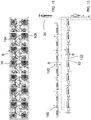
- Figures 2 to 5 show in more detail the inside of a second embodiment of the invention.
- the parking system 1 of Figures 2 to 5 is conceived for storing a plurality of two wheeled vehicles 100 such as bicycles, or the like.
- the system comprises a storage enclosure 2 with at least one opening 12 for introducing and extracting said vehicles 100 to be stored in said parking system 1.
- the enclosure 2 is a substantially closed space, however it cannot be discarded that it is partially open, e.g. at the roof area.
- the parking system 1 further comprises a first carrousel type transporting device 4 arranged inside the enclosure 2.
- This carrousel type transporting device 4 comprises a carrousel guiding path 6 defining a guiding direction 8 and a plurality of first single vehicle holding devices 10.
- Each of the first vehicle holding devices 10 is intended for holding a corresponding single vehicle 100. As it is apparent from the Figures, each first vehicle holding device 10 is movable along the guiding path 6 in the guiding direction 8.
- the guiding path 6 of this embodiment is formed by an upper and lower rail, each defining a closed guide in which the guiding hubs 32 of the first vehicle holding devices 10 is guided.
- the main object of the invention is to provide a two wheeled vehicle parking system which is optimized in terms of public space occupation in the street and which is easy to install and to enlarge.
- the vehicle holding devices 10 are configured to hold the corresponding vehicle 100 such that in operation of said parking system 1, the handlebar 102 of said corresponding vehicle 100 is oriented crosswise to said guiding direction 8.
- the two wheeled vehicles e.g. bicycles
- they are held in the vehicle holding devices 10 such that the longitudinal plane V of the vehicle is substantially parallel to the guiding path 6 (See Figure 4 ).
- This solution is also better in terms of modularity because the enlargement of the parking system capacity requires nothing but growing in the longitudinal direction of the parking system, while maintaining its width.
- the carrousel type transporting device 4 has a first and a second branches 24, 26.
- the first and second branches 24, 26 are linear and parallel to each other. At their ends, the first and second branches 24, 26 are mutually connected with connecting curved sections 28. From the figures it is clear that the vehicle holding device 10, when arriving at the end of each branch, follows the curved sections according to the direction defined by the tangency line of the corresponding curve as in Figure 4 .
- Figure 3 shows that it is especially preferrable that the carrousel guiding path 6 lies on a plane P, to spare as much vertical room as possible.
- the holding devices 10 are configured to hold the vehicles 100 with one first wheel 104 above a second wheel 106. Indeed, the bicycles are held in vertical position, that is the centre of the first and second wheels 104, 106 lies on a line L1 substantially perpendicular to a horizontal plane. This provides for a more compact configuration, increasing the capacity of the parking system 1.
- the parking system 1 of this embodiment comprises also a second carrousel type transporting device 20 arranged inside said enclosure 2 side by side with the first carrousel type transporting device 4.
- the second one also comprises a carrousel guiding path 6 defining a guiding direction 8 and a plurality of second single vehicle holding devices 22.
- Each of the second vehicle holding devices 22 are movable along the guiding path 6 of the second carrousel transporting device 20 in the guiding direction 8.
- the second single vehicle holding devices 22 hold one single vehicle 100 and are movable along the guiding path 6 in the guiding direction 8. Furthermore, this second single vehicle holding devices are conceived to hold small vehicles such as scooter or e-scooter. To this end, the second single vehicle holding devices 22 are basket shaped and dimensioned to receive a scooter like vehicle 100.
- first and second vehicle holding devices 10 and 22 could both be mounted in one same carrousel.
- the enclosure 2 is also mounted on a bridging frame 14 mounted on a ground level G, said bridging frame 14 being raised at least two meters above the ground level G.
- the floor height h that is the free space for walking below the floor of the parking system, ranges between 2,2 and 2,6 m.
- the overall height H of the parking system 1, measured from the ground level to the roof 16, ranges from 4,5 to 6 meters, and especially preferably from 4, 7 to 5 m.
- the overall width W of the parking system 1 ranges from 2 to 5 meters and the overall length L ranges from 10 to 15 m.
- the parking system also comprises two vehicle elevation devices 30 movable between the ground level G and the corresponding opening 12 level for delivering the vehicles 100 to the first or second single vehicle holding devices 10, 22.
- the parking system 1 of the invention can operate 24/7 without problems.
- the parking system 1 comprises automated control means. These control means, not shown in detail, are functionally associated to said first carrousel type transporting device 4 for autonomously controlling the storage of the vehicles 100.
- the carrousel is driven in order for a free space to be available at the opening 12. Then the first holding device 10 is automatically driven upwards to be inserted in the free space of the carrousel.
- the second carrousel type transporting device 20 comprises also automated control means for autonomously controlling the storage of the vehicles 100.
- the first holding device 10 comprises an L shaped body with a concave cross section configured to simultaneously receive both wheels of said vehicle 100, and a biasing stopper movable between a loose position in which said vehicle 100 can be separated from said first holding device and a biased position in which said stopper urges said vehicle against the base of said L shaped body.
- FIG. 6 to 9 is the slim version of the previous embodiment of Figures 2 to 5 .
- this embodiment shows more clearly the first holding device 10 conceived for bicycles.
- This device is an L shaped concave holding frame in which the vehicle wheels are fitted.
- the first holding device 10 could simply be a pair of hooks for hanging the bicycle's handlebar in the corresponding direction crosswise to said guiding direction 8.
- the delivery area 34 is arranged crosswise to the longitudinal direction of the parking system 1. For the rest of the system, reference is made to previous paragraphs.
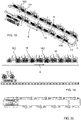
- FIG. 14 to 17 differs from the others in that in this embodiment the holding devices 10 are configured to hold said vehicle 100 with one first wheel 104 in front of the second wheel 106.
- the first wheel 104 is the front wheel and the second wheel 106 is the rear wheel and the vehicle is arranged such that the centre of the first and second wheels 104, 106 lie on a line substantially parallel to an horizontal plane.
- the holding devices 10 hold the corresponding bicycles 100 in a way that the handlebar 102 is oriented crosswise to said guiding direction 8.
- Another relevant difference in this case is that the vehicles 100 are only suspended from the holding devices 10.
- the parking system also includes solar panels 18 on the rooftop.
Landscapes
- Engineering & Computer Science (AREA)
- Mechanical Engineering (AREA)
- Warehouses Or Storage Devices (AREA)
- Handcart (AREA)
Priority Applications (3)
| Application Number | Priority Date | Filing Date | Title |
|---|---|---|---|
| EP20382990.8A EP4001070B1 (de) | 2020-11-16 | 2020-11-16 | Parksystem zum abstellen einer vielzahl von zweiradfahrzeugen |
| ES20382990T ES3035557T3 (en) | 2020-11-16 | 2020-11-16 | Parking system for storing a plurality of two wheeled vehicles |
| PCT/EP2021/081719 WO2022101480A1 (en) | 2020-11-16 | 2021-11-15 | Parking system for storing a plurality of two wheeled vehicles |
Applications Claiming Priority (1)
| Application Number | Priority Date | Filing Date | Title |
|---|---|---|---|
| EP20382990.8A EP4001070B1 (de) | 2020-11-16 | 2020-11-16 | Parksystem zum abstellen einer vielzahl von zweiradfahrzeugen |
Publications (3)
| Publication Number | Publication Date |
|---|---|
| EP4001070A1 true EP4001070A1 (de) | 2022-05-25 |
| EP4001070B1 EP4001070B1 (de) | 2025-05-14 |
| EP4001070C0 EP4001070C0 (de) | 2025-05-14 |
Family
ID=73642820
Family Applications (1)
| Application Number | Title | Priority Date | Filing Date |
|---|---|---|---|
| EP20382990.8A Active EP4001070B1 (de) | 2020-11-16 | 2020-11-16 | Parksystem zum abstellen einer vielzahl von zweiradfahrzeugen |
Country Status (3)
| Country | Link |
|---|---|
| EP (1) | EP4001070B1 (de) |
| ES (1) | ES3035557T3 (de) |
| WO (1) | WO2022101480A1 (de) |
Citations (10)
| Publication number | Priority date | Publication date | Assignee | Title |
|---|---|---|---|---|
| JP2000213194A (ja) * | 1999-01-27 | 2000-08-02 | Nkk Corp | 立体駐輪場 |
| JP2006152537A (ja) * | 2004-11-25 | 2006-06-15 | Jfe Plant & Service Corp | 自転車駐輪設備 |
| WO2010091275A2 (en) * | 2009-02-08 | 2010-08-12 | Perry North | Automated bike parking system |
| JP4983167B2 (ja) * | 2006-09-06 | 2012-07-25 | Jfeエンジニアリング株式会社 | 機械式自転車駐輪設備 |
| WO2013120141A1 (en) * | 2012-02-17 | 2013-08-22 | Lee Adrian Min Yan | Remote storage system |
| AU2015275218A1 (en) * | 2014-12-19 | 2016-07-07 | Bert Kroupa | Method, system and apparatus for vehicle storage |
| CN107605191A (zh) * | 2017-08-25 | 2018-01-19 | 五邑大学 | 一种翻转式自行车车库 |
| CN108560962A (zh) | 2018-05-31 | 2018-09-21 | 广东工业大学 | 悬挂式自动存取自行车停车装置 |
| CN208039936U (zh) * | 2017-07-14 | 2018-11-02 | 厦门魔方互动科技有限公司 | 一种自行车停放系统 |
| US20190366862A1 (en) * | 2018-06-05 | 2019-12-05 | Mark A. Anton | Charging stations for bikes and e-scooters |
-
2020
- 2020-11-16 ES ES20382990T patent/ES3035557T3/es active Active
- 2020-11-16 EP EP20382990.8A patent/EP4001070B1/de active Active
-
2021
- 2021-11-15 WO PCT/EP2021/081719 patent/WO2022101480A1/en not_active Ceased
Patent Citations (10)
| Publication number | Priority date | Publication date | Assignee | Title |
|---|---|---|---|---|
| JP2000213194A (ja) * | 1999-01-27 | 2000-08-02 | Nkk Corp | 立体駐輪場 |
| JP2006152537A (ja) * | 2004-11-25 | 2006-06-15 | Jfe Plant & Service Corp | 自転車駐輪設備 |
| JP4983167B2 (ja) * | 2006-09-06 | 2012-07-25 | Jfeエンジニアリング株式会社 | 機械式自転車駐輪設備 |
| WO2010091275A2 (en) * | 2009-02-08 | 2010-08-12 | Perry North | Automated bike parking system |
| WO2013120141A1 (en) * | 2012-02-17 | 2013-08-22 | Lee Adrian Min Yan | Remote storage system |
| AU2015275218A1 (en) * | 2014-12-19 | 2016-07-07 | Bert Kroupa | Method, system and apparatus for vehicle storage |
| CN208039936U (zh) * | 2017-07-14 | 2018-11-02 | 厦门魔方互动科技有限公司 | 一种自行车停放系统 |
| CN107605191A (zh) * | 2017-08-25 | 2018-01-19 | 五邑大学 | 一种翻转式自行车车库 |
| CN108560962A (zh) | 2018-05-31 | 2018-09-21 | 广东工业大学 | 悬挂式自动存取自行车停车装置 |
| US20190366862A1 (en) * | 2018-06-05 | 2019-12-05 | Mark A. Anton | Charging stations for bikes and e-scooters |
Also Published As
| Publication number | Publication date |
|---|---|
| EP4001070B1 (de) | 2025-05-14 |
| EP4001070C0 (de) | 2025-05-14 |
| WO2022101480A1 (en) | 2022-05-19 |
| ES3035557T3 (en) | 2025-09-04 |
Similar Documents
| Publication | Publication Date | Title |
|---|---|---|
| US20230257044A1 (en) | Collecting electric scooters | |
| JP2016038668A (ja) | 自動車の運行管理システム | |
| CN100413741C (zh) | 运输系统 | |
| AU2016308666A1 (en) | Cycle parking, storage and sharing | |
| US20160333601A1 (en) | Movable and height-extensible automated bicycle storage | |
| CA2672928A1 (en) | People & cargo transit systems & vehicles | |
| ES1226569U (es) | Banco urbano para estacionamiento y carga de vehículos | |
| EP4001070A1 (de) | Parksystem zum abstellen einer vielzahl von zweiradfahrzeugen | |
| CN208393560U (zh) | 共享童车支架 | |
| CN207345985U (zh) | 一种新型自行车停车装置 | |
| DE102024110718A1 (de) | Gemischte E-Fahrzeug-Ladestation | |
| ITMI20100823A1 (it) | Struttura di parcheggio per velocipedi | |
| CN207129045U (zh) | 一种共享自行车用悬挂式停车装置 | |
| CN212637545U (zh) | 一种多功能电动周转车 | |
| TW201938427A (zh) | 上下直排輪運輸車及軌道系統 | |
| CN208039939U (zh) | 一种组合式移动智能停车箱 | |
| CN209581723U (zh) | 便携式车载电动车 | |
| CN208484762U (zh) | 后驱差速转向行李车 | |
| EP3974299B1 (de) | Verfahren und vorrichtung zur aufbewahrung von rollern | |
| CN102390380A (zh) | 城市空中的士系统 | |
| JP2009052264A (ja) | 帰宅支援駐輪システム及び帰宅支援駐輪システムロケーション決定法 | |
| ITGE20090103A1 (it) | Stazione di noleggio e/o ricarica di mezzi di trasporto elettrici, quali biciclette elettriche, tramite fonti di energia rinnovabile e metodo di noleggio di dette biciclette | |
| Aschauer et al. | WP3 Ecotourism planning | |
| JP2003067795A (ja) | 立体駐輪場システム | |
| CN2696968Y (zh) | 自行车锁车架 |
Legal Events
| Date | Code | Title | Description |
|---|---|---|---|
| PUAI | Public reference made under article 153(3) epc to a published international application that has entered the european phase |
Free format text: ORIGINAL CODE: 0009012 |
|
| STAA | Information on the status of an ep patent application or granted ep patent |
Free format text: STATUS: THE APPLICATION HAS BEEN PUBLISHED |
|
| AK | Designated contracting states |
Kind code of ref document: A1 Designated state(s): AL AT BE BG CH CY CZ DE DK EE ES FI FR GB GR HR HU IE IS IT LI LT LU LV MC MK MT NL NO PL PT RO RS SE SI SK SM TR |
|
| STAA | Information on the status of an ep patent application or granted ep patent |
Free format text: STATUS: REQUEST FOR EXAMINATION WAS MADE |
|
| 17P | Request for examination filed |
Effective date: 20221125 |
|
| RBV | Designated contracting states (corrected) |
Designated state(s): AL AT BE BG CH CY CZ DE DK EE ES FI FR GB GR HR HU IE IS IT LI LT LU LV MC MK MT NL NO PL PT RO RS SE SI SK SM TR |
|
| GRAP | Despatch of communication of intention to grant a patent |
Free format text: ORIGINAL CODE: EPIDOSNIGR1 |
|
| STAA | Information on the status of an ep patent application or granted ep patent |
Free format text: STATUS: GRANT OF PATENT IS INTENDED |
|
| INTG | Intention to grant announced |
Effective date: 20241220 |
|
| GRAS | Grant fee paid |
Free format text: ORIGINAL CODE: EPIDOSNIGR3 |
|
| GRAA | (expected) grant |
Free format text: ORIGINAL CODE: 0009210 |
|
| STAA | Information on the status of an ep patent application or granted ep patent |
Free format text: STATUS: THE PATENT HAS BEEN GRANTED |
|
| AK | Designated contracting states |
Kind code of ref document: B1 Designated state(s): AL AT BE BG CH CY CZ DE DK EE ES FI FR GB GR HR HU IE IS IT LI LT LU LV MC MK MT NL NO PL PT RO RS SE SI SK SM TR |
|
| REG | Reference to a national code |
Ref country code: GB Ref legal event code: FG4D |
|
| REG | Reference to a national code |
Ref country code: CH Ref legal event code: EP |
|
| REG | Reference to a national code |
Ref country code: DE Ref legal event code: R096 Ref document number: 602020051204 Country of ref document: DE |
|
| REG | Reference to a national code |
Ref country code: IE Ref legal event code: FG4D |
|
| U01 | Request for unitary effect filed |
Effective date: 20250605 |
|
| U07 | Unitary effect registered |
Designated state(s): AT BE BG DE DK EE FI FR IT LT LU LV MT NL PT RO SE SI Effective date: 20250616 |
|
| REG | Reference to a national code |
Ref country code: ES Ref legal event code: FG2A Ref document number: 3035557 Country of ref document: ES Kind code of ref document: T3 Effective date: 20250904 |
|
| PG25 | Lapsed in a contracting state [announced via postgrant information from national office to epo] |
Ref country code: GR Free format text: LAPSE BECAUSE OF FAILURE TO SUBMIT A TRANSLATION OF THE DESCRIPTION OR TO PAY THE FEE WITHIN THE PRESCRIBED TIME-LIMIT Effective date: 20250815 Ref country code: NO Free format text: LAPSE BECAUSE OF FAILURE TO SUBMIT A TRANSLATION OF THE DESCRIPTION OR TO PAY THE FEE WITHIN THE PRESCRIBED TIME-LIMIT Effective date: 20250814 |
|
| PG25 | Lapsed in a contracting state [announced via postgrant information from national office to epo] |
Ref country code: PL Free format text: LAPSE BECAUSE OF FAILURE TO SUBMIT A TRANSLATION OF THE DESCRIPTION OR TO PAY THE FEE WITHIN THE PRESCRIBED TIME-LIMIT Effective date: 20250514 |
|
| PG25 | Lapsed in a contracting state [announced via postgrant information from national office to epo] |
Ref country code: HR Free format text: LAPSE BECAUSE OF FAILURE TO SUBMIT A TRANSLATION OF THE DESCRIPTION OR TO PAY THE FEE WITHIN THE PRESCRIBED TIME-LIMIT Effective date: 20250514 |
|
| PG25 | Lapsed in a contracting state [announced via postgrant information from national office to epo] |
Ref country code: RS Free format text: LAPSE BECAUSE OF FAILURE TO SUBMIT A TRANSLATION OF THE DESCRIPTION OR TO PAY THE FEE WITHIN THE PRESCRIBED TIME-LIMIT Effective date: 20250814 |
|
| PG25 | Lapsed in a contracting state [announced via postgrant information from national office to epo] |
Ref country code: IS Free format text: LAPSE BECAUSE OF FAILURE TO SUBMIT A TRANSLATION OF THE DESCRIPTION OR TO PAY THE FEE WITHIN THE PRESCRIBED TIME-LIMIT Effective date: 20250914 |
|
| U20 | Renewal fee for the european patent with unitary effect paid |
Year of fee payment: 6 Effective date: 20251126 |
|
| PG25 | Lapsed in a contracting state [announced via postgrant information from national office to epo] |
Ref country code: SM Free format text: LAPSE BECAUSE OF FAILURE TO SUBMIT A TRANSLATION OF THE DESCRIPTION OR TO PAY THE FEE WITHIN THE PRESCRIBED TIME-LIMIT Effective date: 20250514 |
|
| PG25 | Lapsed in a contracting state [announced via postgrant information from national office to epo] |
Ref country code: CZ Free format text: LAPSE BECAUSE OF FAILURE TO SUBMIT A TRANSLATION OF THE DESCRIPTION OR TO PAY THE FEE WITHIN THE PRESCRIBED TIME-LIMIT Effective date: 20250514 |
|
| PG25 | Lapsed in a contracting state [announced via postgrant information from national office to epo] |
Ref country code: SK Free format text: LAPSE BECAUSE OF FAILURE TO SUBMIT A TRANSLATION OF THE DESCRIPTION OR TO PAY THE FEE WITHIN THE PRESCRIBED TIME-LIMIT Effective date: 20250514 |
|
| PGFP | Annual fee paid to national office [announced via postgrant information from national office to epo] |
Ref country code: ES Payment date: 20251201 Year of fee payment: 6 |
|
| PLBE | No opposition filed within time limit |
Free format text: ORIGINAL CODE: 0009261 |
|
| STAA | Information on the status of an ep patent application or granted ep patent |
Free format text: STATUS: NO OPPOSITION FILED WITHIN TIME LIMIT |
|
| REG | Reference to a national code |
Ref country code: CH Ref legal event code: L10 Free format text: ST27 STATUS EVENT CODE: U-0-0-L10-L00 (AS PROVIDED BY THE NATIONAL OFFICE) Effective date: 20260325 |
|
| 26N | No opposition filed |
Effective date: 20260217 |