EP4001075A1 - Boîte pour véhicules à deux roues ou similaire - Google Patents
Boîte pour véhicules à deux roues ou similaire Download PDFInfo
- Publication number
- EP4001075A1 EP4001075A1 EP21209824.8A EP21209824A EP4001075A1 EP 4001075 A1 EP4001075 A1 EP 4001075A1 EP 21209824 A EP21209824 A EP 21209824A EP 4001075 A1 EP4001075 A1 EP 4001075A1
- Authority
- EP
- European Patent Office
- Prior art keywords
- engagement
- shell
- interlocking
- locking
- coupling
- Prior art date
- Legal status (The legal status is an assumption and is not a legal conclusion. Google has not performed a legal analysis and makes no representation as to the accuracy of the status listed.)
- Granted
Links
Images



Classifications
-
- B—PERFORMING OPERATIONS; TRANSPORTING
- B62—LAND VEHICLES FOR TRAVELLING OTHERWISE THAN ON RAILS
- B62J—CYCLE SADDLES OR SEATS; AUXILIARY DEVICES OR ACCESSORIES SPECIALLY ADAPTED TO CYCLES AND NOT OTHERWISE PROVIDED FOR, e.g. ARTICLE CARRIERS OR CYCLE PROTECTORS
- B62J9/00—Containers specially adapted for cycles, e.g. panniers or saddle bags
- B62J9/20—Containers specially adapted for cycles, e.g. panniers or saddle bags attached to the cycle as accessories
- B62J9/23—Containers specially adapted for cycles, e.g. panniers or saddle bags attached to the cycle as accessories above or alongside the rear wheel
-
- B—PERFORMING OPERATIONS; TRANSPORTING
- B62—LAND VEHICLES FOR TRAVELLING OTHERWISE THAN ON RAILS
- B62J—CYCLE SADDLES OR SEATS; AUXILIARY DEVICES OR ACCESSORIES SPECIALLY ADAPTED TO CYCLES AND NOT OTHERWISE PROVIDED FOR, e.g. ARTICLE CARRIERS OR CYCLE PROTECTORS
- B62J9/00—Containers specially adapted for cycles, e.g. panniers or saddle bags
- B62J9/20—Containers specially adapted for cycles, e.g. panniers or saddle bags attached to the cycle as accessories
- B62J9/24—Containers specially adapted for cycles, e.g. panniers or saddle bags attached to the cycle as accessories on specially adapted racks, e.g. for top or side cases
-
- B—PERFORMING OPERATIONS; TRANSPORTING
- B62—LAND VEHICLES FOR TRAVELLING OTHERWISE THAN ON RAILS
- B62H—CYCLE STANDS; SUPPORTS OR HOLDERS FOR PARKING OR STORING CYCLES; APPLIANCES PREVENTING OR INDICATING UNAUTHORIZED USE OR THEFT OF CYCLES; LOCKS INTEGRAL WITH CYCLES; DEVICES FOR LEARNING TO RIDE CYCLES
- B62H5/00—Appliances preventing or indicating unauthorised use or theft of cycles; Locks integral with cycles
- B62H5/001—Preventing theft of parts or accessories used on cycles, e.g. lamp, dynamo
Definitions
- the present invention relates to a device for carrying a load such as a removable trunk for a two-wheeled vehicle or similar.
- 'load' is used here to mean a variety of objects which can be transported either directly or by means of a container.
- a load can be understood as any type of movable item (a bag, a tool, a personal item or other) to be transported or even only to be stored by means of a container which can be detachably attached to the vehicle in such a way that it is integral with it during transport.
- the container can be in turn declined in various forms such as a basket, a generic closed, closable, partially open, or open container.
- the container is at least partially closed to protect unwanted access to the contents.
- the invention relates to devices comprising:
- This particular type of trunk has the advantage that it can be separated from the vehicle and used as a transport bag.
- the trunks on the market have complicated and heavy mechanisms for removable fastening to the vehicle.
- Utility model patent JP3227762U illustrates a trolley body that can be detachably attached to the frame of a bicycle by means of a movable support that engages with a fixed base by means of a movable guiding member that engages with the movable support and guides it along an engagement stroke at the base; when engaged, a hooked member takes care of keeping the trolley body in the engagement position.
- the applicant has improved what is already known according to the invention claimed and described below in order to introduce a device which solves the problem of simplifying the mechanisms for temporarily attaching the trunk to the vehicle, in a solution which is easy to operate (even with a single hand of a single user) and integrates in the same device the requirements of easy engagement and disengagement to the frame, protection of access to the contents, undesired removal of the device, stable fixing to the frame of the vehicle even when the latter is in motion.
- the invention comprises at least one coupling member, preferably two or possibly more than two coupling members distributed in a predetermined pattern along an axis substantially transverse to the direction of the engagement/disengagement stroke, whereby the trunk, by means of an interlocking member, is engaged to the frame of the vehicle housing an interlocking member.
- the invention introduces a particular locking member comprising a swinging lever which can swing about an axis disposed on the stationary part of the frame; the free end of said locking member , intended as the end opposed to the hinge around which the swinging lever oscillates, is conceived in such a way as to overlap and engage with the upper half-shell of the trunk in such a way as to realize the fixing of the container to the vehicle while binding at the same time the upper half-shell, which acts as a lid of the trunk , with the base of the trunk itself.
- the movement to be carried out in order to fix and separate the trunk to the vehicle is simplified by a minimum number of movements that are easy to carry out, both as regards the fixing of the box to the vehicle frame, and as regards the locking of the same in a stable position.
- the execution embodiments may be different, depending on the aesthetic form of the trunk, the type of vehicle, the material with which the trunk is made, without departing from the context of the invention.
- the locking members can be activated or deactivated by means of a key activation/deactivation mechanism.
- a preferred embodiment comprise at least one coupling tooth, arranged in an horizontal or slightly inclined plane and oriented in the direction of the engagement stroke, while the interlocking member accommodates an interlocking seat comprising at least one elongated top plate, disposed transversal to the direction of the engagement/disengagement stroke and having two long peripheral edges and two short peripheral edges, said plate being supported at the short peripheral edges by two vertical supports cooperating with said interlocking teeth to prevent transversal movement of said interlocking member when in engagement position with said interlocking member .
- the configuration and distribution of the hooks and of the corresponding and cooperating interlocking seats may be different and substantially optimised with reference to the contingent boundary conditions defined by the structure of the vehicle and/or by the aesthetic shape of the three-dimensional shell forming the trunk.
- a possible embodiment is implemented in such a way that the interlocking seat is provided with end-stroke means cooperating with said interlocking members in stopping the engagement stroke and at the same time binding the coupling members with the interlocking member in a locked position wherein translations different from the movement of the disengagement stroke are prevented.
- the hooks can be envisaged associated with the vehicle part and the flaps associated with the trunk.
- a further form of implementation which is not limiting and can be freely combined with the other possible forms of implementation, envisages the presence of cooperating guiding and centring means which allow the trunk to be positioned in a relative tooth centring position with respect to the seat and to subsequently bring the trunk into a condition of engagement with a single guided translation.
- a preferred embodiment provides that these are constituted by a lever mounted oscillating around an axis transversal to the direction of the engagement/disengagement stroke of, for example, the interlocking member and by the coupling member.
- Said locking lever is advantageously provided at or near the end of the coupling member, which is rearward, with reference to the direction of the engagement stroke of the interlocking member in said coupling member.
- said lever is movable angularly, alternatively in a position of non-interference with the three-dimensional shell engaged on said coupling member, whereby said coupling member and said shell are movable together along the engagement/disengagement stroke of said coupling member, and in a position tilted upwards against the rear side of said three-dimensional shell, wherein it constitutes a stop to the free movement of the shell and consequently of the interlocking member in the direction of disengagement of the latter from the coupling member .
- the movement of the lever may be controlled by an angular velocity damping mechanism, by means of at least one slow motion device positioned in proximity of said transversal axis about which said oscillating lever oscillates, said oscillatory motion control mechanism optionally comprising a further elastic member for activating said oscillatory motion.
- the lever or, more generally, the locking member comprises further controlled locking members acting in the upwardly tilted position of the lever and activated and deactivated simultaneously therewith, acting in the direction of the engagement stroke and cooperating with corresponding collisions in the engaging member so as to exert a calibrated and predetermined force to hold said engaging member in the engagement position with the interlocking member.
- said mechanism for activating/deactivating the locking members and in particular the locking lever advantageously comprises retention means of said locking lever in the raised locking position against the rear side of the three-dimensional shell, said retention means being controllable in the activation/deactivation position by means of a key mechanism.
- the key mechanism enables or disables said lever retaining means to a part of the shell, said retaining means being held in the engaged position by one or more spring members and controlled by a pressure mechanism for releasing in the engaged position of said retaining means.
- the trunk may be realized comprising a frame adapting device intended to be fixed in an adjustable and removable manner to one or more parts of the frame of said two-wheeled vehicle and comprising a support zone and one or more support and/or anchoring zones for the engagement member.
- said frame adaptor comprises at least one or a plurality of manually adjustable joints for swinging the support zone about one or more swing axes and/or translating along one or more translation axes in accordance with a desired orientation of the trunk when in the engaged position and/or that said frame adaptor comprises one or more clamp bodies for clamping to cylindrical parts of the frame of said two-wheeled vehicle.
- a two-wheeled vehicle 1 has at its rear end a luggage rack bracket 2 to which a trunk 3 can be attached.
- the trunk is provided with means for transporting the trunk in a separate condition from the vehicle; in a preferred embodiment, the trunk is provided with a handle 13 positioned in the upper part of the half shell 103 which, in addition to being used for transport, may serve for opening the trunk and for engagement and/or disengagement from the vehicle.
- a strap or belt attached to one or both half shells to which it is stably connected or removably connected by means of coupling and release terminals.
- the trunk 3 may comprise a three-dimensional shell of material that is rigid, soft, but such that it maintains a predetermined three-dimensional shape, or floppy material in the form of a leaf, sheet or similar.
- the three-dimensional trunk shell is divided according to a horizontal or substantially horizontal dividing line 403, i.e. also slightly inclined into two half-shells 103, 203 of which a lower half-shell 103 and an upper half-shell 203.
- the upper half-shell 203 is articulated to the lower half-shell by means of articulation means, such as a hinge shown or comprising a jumper of piece material with one or both half-shells.
- the articulation is provided along a segment of the separation line 603, shown in figure a, which is provided substantially along the front side of the trunk 3 with reference to the condition fitted to the vehicle 1.
- the remaining segment of the separation line 403 extends from either end of the joint line 603 of the two half shells 103, 203 to each other.
- Hinging along the line of articulation 603 or along part of it is intended to open the trunk which is done by rotation between the two shells and is achieved, for example, by mechanical members such as one or more hinges arranged along the line of articulation 603.
- opening limiting mechanisms can be combined with the hinge members to limit the mutual angular displacement between the base and the lid to a predetermined adjustable or fixed angular width.
- FIG. 1 may depict one or a combination of spring members which are stressed, from an initial angular position of the lid with respect to the base, in the closing and/or closing direction for at least one leg of the angular opening/closing path towards a compression or extension position with respect to the angular rest position of the spring member combination of motion damping members interposed between the base and the lid which act against the force exerted by the spring and the acceleration of gravity in the opening and closing direction.
- Removable means of connection of the two half-shells 103, 203 can be provided along the separation line 403, which can be of any type.
- Said means may comprise, for example, magnetic means extending along the entire separation line 403 and holding the two half-shells against each other with a force that can be overcome by manual action.
- said means may be means for interlocking the two half-shells along said separation line 403, acting along the whole said line or at one or more predetermined points, and which may have actuating members, for controlling in a condition of mutual engagement and disengagement and thus releasing or restraining the two half-shells respectively from each other and against each other.
- An alternative variant of the means of connecting the two half-shells to each other may be two zips.
- the two zips are separated from each other and each of said zips covers one half of the segment of separation line connecting the two ends of the articulation segment 603 and departing respectively from one of said two ends of the articulation segment 603 and terminating at the central area of the rear side of the trunk .
- a further variant embodiment may comprise, for example, a single hinge.
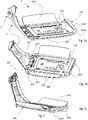
- an interlocking member 4 an embodiment of which is presented in Figures 2a-2c , intended to be fixed by suitable means to the vehicle bracket 2 of the vehicle 1.
- the interlocking member 4 may be anchored to the bracket or carrier 2 of the frame or, when the vehicle does not have such a bracket or in any case the bracket is not suitable for the purpose, the interlocking member 4 may be anchored to the frame by means of an adapter member 6.
- the interlocking member 4 is provided with frame anchoring members (404) such as, for example, a plurality of holes that may be threaded to accommodate joining members to the vehicle frame such as screws and/or bolts.
- the interlocking member 4 cooperates with an attachment member 5 intended to be permanently fixed to the bottom side, i.e. the bottom side of the trunk, i.e. the bottom half shell 103.
- the coupling member 5, as also specified below, is designed to be brought into a position of engagement with the interlocking member (5) by means of a movement also referred to herein as an engagement stroke.
- an engagement stroke At the end of the engagement stroke, the trunk (to which the coupling member is integral) is in a stable position on the frame (to which the interlocking member is integral).
- the release between the trunk and the vehicle comprise a disengagement stroke that releases the trunk from the vehicle allowing the user to remove the trunk, preferably carrying it by the knob 13.
- the interlocking member 4 comprises a plate 204 fixable by screws to the bracket 2 of the vehicle 1 or to the adapter member 6, which plate has an interlocking seat 104 disposed in the front side of the plate itself, with reference to the trunk engagement stroke, and projecting from its upper side.
- the interlocking seat 104 is herein realized in the form of an elongated plate 1104, having two long peripheral edges and two short peripheral edges, arranged in a plane substantially parallel to the plane of the plate and orthogonal to the direction of advancement of the vehicle, supported at the short peripheral edges by two supports 2104.
- the two supports 2104 thus rigidly connect the plate to the plate 4, being able to be made of piece with the plate and/or with the plate.
- the coupling member 5 also comprises a plate intended to be fixed to the bottom of the lower half shell 103.
- a plate intended to be fixed to the bottom of the lower half shell 103.
- the plate forming the interlocking member 5 is fixed to a bottom counterplate (not illustrated) which may be provided internally to the lower half-shell 103 along the bottom side thereof or may also constitute a partial cup or partial coating of said bottom side.
- the combination of plate and counterplate cooperate for stable anchorage to the bottom of the trunk , stiffening the entire structure and at the same time providing a flat or suitably shaped surface inside the container compartment that facilitates the support and maintenance in position of the objects stored therein.
- said counterplate may be made of two materials having different characteristics, to combine the necessary rigidity required for fixing and compatibility with the contents of the trunk.
- the counterplate may be made of a rigid material exposed in the direction of the plate and one or more rubbery or otherwise soft materials that will not damage a helmet or other objects placed in the trunk.
- the coupling member 5 carries its coupling teeth 105 in positions coinciding with those of the interlocking seat 104 located in the coupling member 4.
- the positions of the teeth 105 and the interlocking seat 104 are such as to allow mutual engagement and disengagement with a single relative translational movement of the two members 4 and 5 in the direction of the longitudinal axis of the vehicle.
- the presence of the teeth exclusively in the front part allows an extremely fast and more precise positioning, since it can be done only in one part and according to a movement not necessarily parallel to the support plane since the rear part of the trunk can be approached also with a short rotation of the shells after the hooks have been inserted in the seat.
- the interlocking seat 104 is also provided with end-stroke means cooperating with said coupling members in stopping the engagement stroke and simultaneously binding the coupling member to the interlocking member in a locked position wherein movements other than the movement of the disengagement stroke are prevented.
- two vertical stop plates 304 ( figures 2b and 2c ) are arranged in front of the interlocking member 4, which collide with as many vertical stop surfaces 405 provided in proximity to the teeth 105, slightly set back and perpendicular to them as shown in figure 3 .
- the engagement configuration can be seen in figure 4a .
- the reciprocal arrangement of the teeth 105 and the stop surfaces 405 provides that the latter are set back with respect to the front of the teeth along the engagement stroke.
- the end-stop surfaces 405 cooperate with the end-stop plates 304 by stopping the engagement stroke in a reciprocal position wherein the teeth 105 protrude slightly outside the engagement seat in favour of the retention of the trunk and of the visual and aesthetic impact, which is pleasing and provides an indication of the correct engagement of the members involved.
- the coupling member 4 and the interlocking member 5 have cooperating guiding and centring means that allow them to be positioned in a relative position of centring of the teeth with respect to the seat and to subsequently bring the trunk into a committed condition with a single guided translation.
- centring and guiding means can be realized in various ways, and according to an executive variant they are constituted by rectilinear prominence 504 arranged longitudinally on the interlocking member 4.
- the rectilinear prominences 504 function as guiding walls of the coupling member 5, which coupling member has a convex central band 505, of elongated shape and longitudinal arrangement, which is confined by two substantially vertical and mutually parallel perimeter walls 1505. Said perimeter walls are spaced to engage smoothly with the two rectilinear projections 504 in the guide of the engagement member 5 when superimposed on the interlocking member 4.
- the invention comprises accompanying, centring and stabilising devices in the engaged position that also act on part of the shell in addition to or as an alternative to the centring and guiding means set out above.
- the invention comprises two side fins 604 disposed in a longitudinal direction and departing from the sides of the plate 204.
- the side fins 604 have an upwardly convex cross-section, with convexity substantially equal to that present in the surface of the lower half-shell 103 with which the fins 604 cooperate in driving in the engaged position and to which lower half-shell said fins provide support to bear the weight of the load of the trunk by limiting deformation of the half-shell 103 and thus of the trunk in general.
- a locking lever 7 is oscillatingly articulated around it. Said lever oscillates about an axis of oscillation perpendicular to the engagement/disengagement and consequently perpendicular to the longitudinal axis of the vehicle.
- This lever carries at its free end a lock mechanism 8 which will be described in more detail below.
- the lever 7 is provided in such a position and with such a shape and such dimensions, so that in the downwardly tilted condition it does not interfere with the three-dimensional shell and the coupling plate 5 which is therefore free to move up and back in the direction of the disengagement stroke from the coupling member 4, making it possible to detach the trunk from the vehicle.
- the locking lever 7 constitutes a retaining stop at least of the lower half shell 103 in the condition of engagement of the coupling member 5 in the coupling member 4, thus preventing the execution of the mutual disengagement stroke of said two members from each other and therefore the detachment of the trunk from the vehicle 1.
- the locking lever is preferably, but not necessarily, associated with an oscillatory motion control mechanism which, advantageously, acts to give uniformity to the movement of the lever itself. This control is more evident in the opening phase where, in most cases, the user does not accompany the lever but leaves it free to open under the action of gravity. In this situation, the control mechanism acts by making the opening movement of the lever more uniform and, in particular, the angular speed, avoiding damage and/or rebounds at the end of the lever stroke and, at the same time, making the opening smoother and more pleasant.
- the damping effect is obtained by the combination of a damping member 407 and an elastic member 507.
- the damping member 407 is arranged coaxially to the axis of oscillation of the lever, it acts according to known techniques such as, for example, dynamic friction between mechanical parts or by fluid-dynamic or magnetic action opposing a force that increases with increasing speed.
- the spring member 507 consists of a helical spring pre-calibrated to act in the opening direction of the lever and only for the first part of the stroke. In this way, with a simple and inexpensive device, it is possible to obtain the effect of greater acceleration limited to the first part of the stroke and consequently to reach more rapidly the phase at constant speed wherein the action of the spring is cancelled and the damping member is fully operative.
- the spring 507's opening thrust action also favours the stationing of the lever in the closed position, by virtue of the force that is transferred to the retaining hook 408 increasing its traction on the retaining cylinder 509.
- this prevents unwanted opening of the mechanism when subjected to shocks and/or vibrations received by the frame when the vehicle is moving on rough roads or in abnormal situations such as a fall.
- An activation/deactivation mechanism 8 is associated with the locking lever 7, which allows the said lever to be retained in the raised condition of locking the trunk in the condition of engagement of the coupling member 5 in the interlocking member 4.
- Such activation and deactivation mechanisms of the locking lever can advantageously be controlled by a key lock such as indicated by 18 and can be multiple and simultaneously activated with each other.
- the locking lever 7 may contextually have the function of holding the two half-shells 103, 203 in the closed condition of the trunk , or also provide protection against unwanted opening of the trunk by protecting the devices that allow separation between the two half-shells 103 and 203.
- the locking lever 7 in the raised locking condition can operate in a locked position against sliding in the opening direction of the two zip sliders.
- a first part of the members 8 which are part of the activation/deactivation mechanism, which, as anticipated, may comprise a key lock to allow or prevent opening by the user.
- a second and remaining part of the members 9 constituting the activation/deactivation mechanism is located on the surface of the trunk in a position to face and interact with said first part of members 8 when the lever 7 is in the retaining position.
- Figures 5a and 5b show, respectively, the components located at the end of the lever 7 and of the trunk according to the embodiment presented herein, which is preferred but not limiting to the invention.
- the tang 508 is further provided with an appendage 2508, which guides and controls the retaining hook 408 and prevents it from moving or not.
- the retaining hook 408 is oscillatingly mounted on a cylindrical support 608, which support 608 also acts as a pivot-guide for a helical spring 108 ( figure 6 ) whose elastic force acts on the hook 408 forcing it into a raised position.
- the tang 508 is shown in the unlocked condition and the appendage 2508 does not interfere with the retaining hook 408.
- pressing the button 208 by a user results in a force opposing the elastic force of the spring 108 and, depending on its intensity, in rotation of the hook 408 around the pin 608 resulting in downward displacement of the unrestrained end of the hook itself.
- Rotation of the hook 408 leads to release from the pin 509 and consequently to release of the locking member 7 from the three-dimensional shell of the trunk, with the lever free to swing and move into the open position.
- the tang 508 is rotated such that the appendage 1508 is in contact with the hook 408 and exerts an upward force on it such that the above-described movement of release as a result of pressing the button 508 is prevented.
- the hook end is then engaged with the pin 509 and the trunk is engaged to the interlocking member, i.e., the vehicle.
- the mutual engagement means between the lever and the trunk comprise a retractable member , also activated by the key mechanism by means of the appendage 1508 of the tang 508, articulated to make an excursion in the direction of the half shell and engage a corresponding locking seat 39.
- the engagement of said retractable member in the seat increases the locking power between the lever and the trunk, in addition to what is already offered by the hook 408.
- the retractable member comprises a rod 308, cylindrical in shape, disposed on the locking member 7 and oriented in a direction substantially tangential to the oscillatory path of said locking member around said axis of oscillation, said rod 308 being intended to be received by a slotted body 309 positioned on the half-shell 203 of the trunk in a plane orthogonal to said rod when the condition of engagement of the mutual engagement means occurs.
- the slotted body 309 has a coupling opening 409 having a shape and size substantially equal to the cylindrical sectional shape of the rod 308.
- the combined action of the pin and the slot has the advantageous effect of centring the engagement body and, when engaged, limiting the reciprocal movement of the lever end by preventing misalignment or undesirable movement.
- the lever 7 When not engaged to the trunk , the lever 7 can be retracted to the closed position by placing the free end interlocked with the plate 204, which plate 204 comprise s an opening and a resting engagement member 704 arranged to be engaged with the hook 408 of the lever retention mechanism 7. This makes it safer to drive the vehicle without a trunk and prevents damage due to free swinging of the lever subject to the vibrations and shocks of vehicle movement.
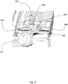
- the engagement position is shown in figure 6 , where some components have been omitted to facilitate the representation of the engagement state.
- the hook 408 cooperating with the pin 509 is shown, where the hook is supported by a helical spring 108 to hold the hook in a raised position and facilitate the engagement operation.
- the force of the spring is counteracted by any pressure exerted on the button when it is intended to disengage the trunk , and downward movement of the hook 408 is permitted or not permitted depending on the position of the lock and tang 508.
- Figures 5a and 5b further show a further hooked body 708 provided for engagement in a corresponding engagement seat disposed on the upper half shell 203 of the trunk.
- the hooked body 708 is made of piece with the rod 308, translates integral with it under the action of the tang 508 and introduces a further locking action for maintaining the lever in a committed state.
- the body protrudes at the bottom of the hook and is arranged to interact directly with the appendage 1508 so as to translate towards the trunk when actuated by the rotational motion of the appendage itself.
- the locking lever 7 may have corresponding engagement members of the slider(s) of the zip(s) connecting the two half-shells 103, 203 to each other and in particular of the gripping tabs of the zip sliders.
- a further characterising aspect of the present invention is related to the presence, in an executive and non-limiting form, of further controlled locking members which act when the lever is in the upward tilted position and are activated and deactivated simultaneously with the movement of the lever 7 during displacement towards the locking position (upward tilted position) and during displacement towards the position of non-interference with the shell, respectively.
- two projections 307 ( figure 2 ) are provided at the base of the lever 7 according to an arrangement in two planes orthogonal to the oscillating axis of the lever and are inserted in corresponding grooves 305 obtained in the rear part of the base of the lower half shell 103, preferably in the coupling member 5.
- the two projections are substantially flat in shape, parallel to each other and spaced apart by a predetermined distance which may vary according to the embodiments, just as the number of said projections 307 integrated in the lever 7 may freely vary without prejudice to the scope of the invention.
- the dimensioning of the projections 307 and the grooves 305 is such that, during insertion, a force is generated in the direction of the engagement stroke between the plates, which contributes to reaching the stop position of the hooking teeth 105 in the seat 104.
- the hooks exert a second calibrated and predetermined force to hold said coupling member (5) in the engagement position with the interlocking member (4).
- the flat conformation of the projections 307 has two faces that cooperate with similar surfaces present in the grooves 305 and prevent the trunk from translating horizontally along an axis transverse to the engagement/disengagement stroke.
- the projections 307 may have an appendage 1307 which, when engaged with the trunk, engages corresponding indentations created in the grooves 305 so as to constitute an impediment to movement of the engagement member , i.e., the trunk, along a direction orthogonal to the engagement member 4 i.e., along an upward or downward direction.
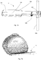
- FIG. 7a shows a possible implementation form of an adaptation device as an object of the invention, comprising a support zone 106 and one or more support and/or anchoring zones 206 mirroring the anchoring members 404 present in the interlocking member 4.
Landscapes
- Engineering & Computer Science (AREA)
- Mechanical Engineering (AREA)
- Vehicle Step Arrangements And Article Storage (AREA)
- Lock And Its Accessories (AREA)
- Purses, Travelling Bags, Baskets, Or Suitcases (AREA)
Applications Claiming Priority (1)
| Application Number | Priority Date | Filing Date | Title |
|---|---|---|---|
| IT102020000028067A IT202000028067A1 (it) | 2020-11-23 | 2020-11-23 | Bauletto amovibile per veicoli a due ruote o simili |
Publications (3)
| Publication Number | Publication Date |
|---|---|
| EP4001075A1 true EP4001075A1 (fr) | 2022-05-25 |
| EP4001075B1 EP4001075B1 (fr) | 2024-07-24 |
| EP4001075C0 EP4001075C0 (fr) | 2024-07-24 |
Family
ID=74557122
Family Applications (1)
| Application Number | Title | Priority Date | Filing Date |
|---|---|---|---|
| EP21209824.8A Active EP4001075B1 (fr) | 2020-11-23 | 2021-11-23 | Boîte pour véhicules à deux roues ou similaire |
Country Status (2)
| Country | Link |
|---|---|
| EP (1) | EP4001075B1 (fr) |
| IT (1) | IT202000028067A1 (fr) |
Citations (4)
| Publication number | Priority date | Publication date | Assignee | Title |
|---|---|---|---|---|
| JPS5758568A (en) * | 1980-09-22 | 1982-04-08 | Honda Motor Co Ltd | Locking device for upper section of car body, such as seat or rear box or the like of autobicycle |
| DE9007222U1 (de) * | 1990-06-29 | 1990-09-06 | Schroll, Stefan, Dipl.-Ing. (FH), 8221 Nußdorf | Halteelement als Diebstahleinrichtung an Fahrrädern |
| JP2001354178A (ja) * | 2000-06-14 | 2001-12-25 | Ogk Co Ltd | 車用バスケットの装着構造 |
| JP3227762U (ja) | 2020-06-11 | 2020-09-17 | 株式会社東京錠前製作所 | 自転車用キャリーカート |
-
2020
- 2020-11-23 IT IT102020000028067A patent/IT202000028067A1/it unknown
-
2021
- 2021-11-23 EP EP21209824.8A patent/EP4001075B1/fr active Active
Patent Citations (4)
| Publication number | Priority date | Publication date | Assignee | Title |
|---|---|---|---|---|
| JPS5758568A (en) * | 1980-09-22 | 1982-04-08 | Honda Motor Co Ltd | Locking device for upper section of car body, such as seat or rear box or the like of autobicycle |
| DE9007222U1 (de) * | 1990-06-29 | 1990-09-06 | Schroll, Stefan, Dipl.-Ing. (FH), 8221 Nußdorf | Halteelement als Diebstahleinrichtung an Fahrrädern |
| JP2001354178A (ja) * | 2000-06-14 | 2001-12-25 | Ogk Co Ltd | 車用バスケットの装着構造 |
| JP3227762U (ja) | 2020-06-11 | 2020-09-17 | 株式会社東京錠前製作所 | 自転車用キャリーカート |
Also Published As
| Publication number | Publication date |
|---|---|
| EP4001075B1 (fr) | 2024-07-24 |
| EP4001075C0 (fr) | 2024-07-24 |
| IT202000028067A1 (it) | 2022-05-23 |
Similar Documents
| Publication | Publication Date | Title |
|---|---|---|
| US7997591B2 (en) | Chassis with retractable wheels | |
| TWI812956B (zh) | 具輔助籃的可轉換兒童推車系統 | |
| US5002304A (en) | Collapsible cart | |
| US5024359A (en) | Bicycle cooler | |
| US20060119057A1 (en) | Backpack with removable handle and wheel assembly | |
| JP7323431B2 (ja) | ポータブルライト | |
| US20120274106A1 (en) | Device for Suspending Objects | |
| EP2907494A1 (fr) | Table pour fauteuil roulant et fauteuil roulant comprenant celle-ci | |
| US6811198B2 (en) | System for storing a load in a vehicle | |
| EP4001075B1 (fr) | Boîte pour véhicules à deux roues ou similaire | |
| EP1963136B1 (fr) | Dispositif de chargement pour vehicules | |
| US7401715B2 (en) | Rotatable strap assembly for a load carrier | |
| EP3277564B1 (fr) | Système de mise en prise | |
| CN117177907A (zh) | 将手提包附接到挂篮架的固定设备 | |
| US20070090140A1 (en) | Packing apparatus | |
| NL2007674C2 (nl) | Aangrijporgaan voor bevestiging van een houder aan een fietsbagagedrager. | |
| CN116922340A (zh) | 工具箱系统 | |
| JP6225006B2 (ja) | ペット用キャリー付きカート | |
| EP4480756B1 (fr) | Agencements pour fixer un porte-charges à un porte-charges | |
| KR100772161B1 (ko) | 카트형 가방 | |
| KR101756872B1 (ko) | 자전거에 설치되는 안전기능을 갖는 수납장치 | |
| KR20210131681A (ko) | 서랍 고정장치 | |
| CA3118372A1 (fr) | Mallette de transport avec boitier pivotant | |
| JP4108261B2 (ja) | 歩行補助具 | |
| GB2075436A (en) | Wheeled carrier, e.g. a shopping trolley |
Legal Events
| Date | Code | Title | Description |
|---|---|---|---|
| PUAI | Public reference made under article 153(3) epc to a published international application that has entered the european phase |
Free format text: ORIGINAL CODE: 0009012 |
|
| STAA | Information on the status of an ep patent application or granted ep patent |
Free format text: STATUS: THE APPLICATION HAS BEEN PUBLISHED |
|
| AK | Designated contracting states |
Kind code of ref document: A1 Designated state(s): AL AT BE BG CH CY CZ DE DK EE ES FI FR GB GR HR HU IE IS IT LI LT LU LV MC MK MT NL NO PL PT RO RS SE SI SK SM TR |
|
| STAA | Information on the status of an ep patent application or granted ep patent |
Free format text: STATUS: REQUEST FOR EXAMINATION WAS MADE |
|
| 17P | Request for examination filed |
Effective date: 20221117 |
|
| RBV | Designated contracting states (corrected) |
Designated state(s): AL AT BE BG CH CY CZ DE DK EE ES FI FR GB GR HR HU IE IS IT LI LT LU LV MC MK MT NL NO PL PT RO RS SE SI SK SM TR |
|
| GRAP | Despatch of communication of intention to grant a patent |
Free format text: ORIGINAL CODE: EPIDOSNIGR1 |
|
| STAA | Information on the status of an ep patent application or granted ep patent |
Free format text: STATUS: GRANT OF PATENT IS INTENDED |
|
| RIC1 | Information provided on ipc code assigned before grant |
Ipc: B62H 5/00 20060101ALN20240126BHEP Ipc: B62J 9/24 20200101ALI20240126BHEP Ipc: B62J 9/23 20200101AFI20240126BHEP |
|
| INTG | Intention to grant announced |
Effective date: 20240301 |
|
| GRAS | Grant fee paid |
Free format text: ORIGINAL CODE: EPIDOSNIGR3 |
|
| GRAA | (expected) grant |
Free format text: ORIGINAL CODE: 0009210 |
|
| STAA | Information on the status of an ep patent application or granted ep patent |
Free format text: STATUS: THE PATENT HAS BEEN GRANTED |
|
| AK | Designated contracting states |
Kind code of ref document: B1 Designated state(s): AL AT BE BG CH CY CZ DE DK EE ES FI FR GB GR HR HU IE IS IT LI LT LU LV MC MK MT NL NO PL PT RO RS SE SI SK SM TR |
|
| REG | Reference to a national code |
Ref country code: GB Ref legal event code: FG4D |
|
| REG | Reference to a national code |
Ref country code: CH Ref legal event code: EP |
|
| REG | Reference to a national code |
Ref country code: IE Ref legal event code: FG4D Ref country code: DE Ref legal event code: R096 Ref document number: 602021016076 Country of ref document: DE |
|
| U01 | Request for unitary effect filed |
Effective date: 20240809 |
|
| U07 | Unitary effect registered |
Designated state(s): AT BE BG DE DK EE FI FR IT LT LU LV MT NL PT SE SI Effective date: 20240827 |
|
| U20 | Renewal fee for the european patent with unitary effect paid |
Year of fee payment: 4 Effective date: 20241024 |
|
| PG25 | Lapsed in a contracting state [announced via postgrant information from national office to epo] |
Ref country code: NO Free format text: LAPSE BECAUSE OF FAILURE TO SUBMIT A TRANSLATION OF THE DESCRIPTION OR TO PAY THE FEE WITHIN THE PRESCRIBED TIME-LIMIT Effective date: 20241024 |
|
| PG25 | Lapsed in a contracting state [announced via postgrant information from national office to epo] |
Ref country code: PL Free format text: LAPSE BECAUSE OF FAILURE TO SUBMIT A TRANSLATION OF THE DESCRIPTION OR TO PAY THE FEE WITHIN THE PRESCRIBED TIME-LIMIT Effective date: 20240724 Ref country code: GR Free format text: LAPSE BECAUSE OF FAILURE TO SUBMIT A TRANSLATION OF THE DESCRIPTION OR TO PAY THE FEE WITHIN THE PRESCRIBED TIME-LIMIT Effective date: 20241025 |
|
| PG25 | Lapsed in a contracting state [announced via postgrant information from national office to epo] |
Ref country code: IS Free format text: LAPSE BECAUSE OF FAILURE TO SUBMIT A TRANSLATION OF THE DESCRIPTION OR TO PAY THE FEE WITHIN THE PRESCRIBED TIME-LIMIT Effective date: 20241124 |
|
| PG25 | Lapsed in a contracting state [announced via postgrant information from national office to epo] |
Ref country code: HR Free format text: LAPSE BECAUSE OF FAILURE TO SUBMIT A TRANSLATION OF THE DESCRIPTION OR TO PAY THE FEE WITHIN THE PRESCRIBED TIME-LIMIT Effective date: 20240724 |
|
| PG25 | Lapsed in a contracting state [announced via postgrant information from national office to epo] |
Ref country code: RS Free format text: LAPSE BECAUSE OF FAILURE TO SUBMIT A TRANSLATION OF THE DESCRIPTION OR TO PAY THE FEE WITHIN THE PRESCRIBED TIME-LIMIT Effective date: 20241024 Ref country code: ES Free format text: LAPSE BECAUSE OF FAILURE TO SUBMIT A TRANSLATION OF THE DESCRIPTION OR TO PAY THE FEE WITHIN THE PRESCRIBED TIME-LIMIT Effective date: 20240724 |
|
| PG25 | Lapsed in a contracting state [announced via postgrant information from national office to epo] |
Ref country code: RS Free format text: LAPSE BECAUSE OF FAILURE TO SUBMIT A TRANSLATION OF THE DESCRIPTION OR TO PAY THE FEE WITHIN THE PRESCRIBED TIME-LIMIT Effective date: 20241024 Ref country code: PL Free format text: LAPSE BECAUSE OF FAILURE TO SUBMIT A TRANSLATION OF THE DESCRIPTION OR TO PAY THE FEE WITHIN THE PRESCRIBED TIME-LIMIT Effective date: 20240724 Ref country code: NO Free format text: LAPSE BECAUSE OF FAILURE TO SUBMIT A TRANSLATION OF THE DESCRIPTION OR TO PAY THE FEE WITHIN THE PRESCRIBED TIME-LIMIT Effective date: 20241024 Ref country code: IS Free format text: LAPSE BECAUSE OF FAILURE TO SUBMIT A TRANSLATION OF THE DESCRIPTION OR TO PAY THE FEE WITHIN THE PRESCRIBED TIME-LIMIT Effective date: 20241124 Ref country code: HR Free format text: LAPSE BECAUSE OF FAILURE TO SUBMIT A TRANSLATION OF THE DESCRIPTION OR TO PAY THE FEE WITHIN THE PRESCRIBED TIME-LIMIT Effective date: 20240724 Ref country code: GR Free format text: LAPSE BECAUSE OF FAILURE TO SUBMIT A TRANSLATION OF THE DESCRIPTION OR TO PAY THE FEE WITHIN THE PRESCRIBED TIME-LIMIT Effective date: 20241025 Ref country code: ES Free format text: LAPSE BECAUSE OF FAILURE TO SUBMIT A TRANSLATION OF THE DESCRIPTION OR TO PAY THE FEE WITHIN THE PRESCRIBED TIME-LIMIT Effective date: 20240724 |
|
| PG25 | Lapsed in a contracting state [announced via postgrant information from national office to epo] |
Ref country code: RO Free format text: LAPSE BECAUSE OF FAILURE TO SUBMIT A TRANSLATION OF THE DESCRIPTION OR TO PAY THE FEE WITHIN THE PRESCRIBED TIME-LIMIT Effective date: 20240724 Ref country code: SM Free format text: LAPSE BECAUSE OF FAILURE TO SUBMIT A TRANSLATION OF THE DESCRIPTION OR TO PAY THE FEE WITHIN THE PRESCRIBED TIME-LIMIT Effective date: 20240724 |
|
| PG25 | Lapsed in a contracting state [announced via postgrant information from national office to epo] |
Ref country code: CZ Free format text: LAPSE BECAUSE OF FAILURE TO SUBMIT A TRANSLATION OF THE DESCRIPTION OR TO PAY THE FEE WITHIN THE PRESCRIBED TIME-LIMIT Effective date: 20240724 |
|
| PG25 | Lapsed in a contracting state [announced via postgrant information from national office to epo] |
Ref country code: SK Free format text: LAPSE BECAUSE OF FAILURE TO SUBMIT A TRANSLATION OF THE DESCRIPTION OR TO PAY THE FEE WITHIN THE PRESCRIBED TIME-LIMIT Effective date: 20240724 |
|
| PLBE | No opposition filed within time limit |
Free format text: ORIGINAL CODE: 0009261 |
|
| STAA | Information on the status of an ep patent application or granted ep patent |
Free format text: STATUS: NO OPPOSITION FILED WITHIN TIME LIMIT |
|
| 26N | No opposition filed |
Effective date: 20250425 |
|
| PG25 | Lapsed in a contracting state [announced via postgrant information from national office to epo] |
Ref country code: MC Free format text: LAPSE BECAUSE OF FAILURE TO SUBMIT A TRANSLATION OF THE DESCRIPTION OR TO PAY THE FEE WITHIN THE PRESCRIBED TIME-LIMIT Effective date: 20240724 |
|
| PG25 | Lapsed in a contracting state [announced via postgrant information from national office to epo] |
Ref country code: IE Free format text: LAPSE BECAUSE OF NON-PAYMENT OF DUE FEES Effective date: 20241123 |
|
| REG | Reference to a national code |
Ref country code: CH Ref legal event code: U11 Free format text: ST27 STATUS EVENT CODE: U-0-0-U10-U11 (AS PROVIDED BY THE NATIONAL OFFICE) Effective date: 20251215 |
|
| U20 | Renewal fee for the european patent with unitary effect paid |
Year of fee payment: 5 Effective date: 20251128 |
|
| PGFP | Annual fee paid to national office [announced via postgrant information from national office to epo] |
Ref country code: GB Payment date: 20251128 Year of fee payment: 5 |
|
| PGFP | Annual fee paid to national office [announced via postgrant information from national office to epo] |
Ref country code: CH Payment date: 20251215 Year of fee payment: 5 |
|
| PG25 | Lapsed in a contracting state [announced via postgrant information from national office to epo] |
Ref country code: HU Free format text: LAPSE BECAUSE OF FAILURE TO SUBMIT A TRANSLATION OF THE DESCRIPTION OR TO PAY THE FEE WITHIN THE PRESCRIBED TIME-LIMIT; INVALID AB INITIO Effective date: 20211123 |
|
| PG25 | Lapsed in a contracting state [announced via postgrant information from national office to epo] |
Ref country code: CY Free format text: LAPSE BECAUSE OF FAILURE TO SUBMIT A TRANSLATION OF THE DESCRIPTION OR TO PAY THE FEE WITHIN THE PRESCRIBED TIME-LIMIT; INVALID AB INITIO Effective date: 20211123 |
|
| PG25 | Lapsed in a contracting state [announced via postgrant information from national office to epo] |
Ref country code: TR Free format text: LAPSE BECAUSE OF FAILURE TO SUBMIT A TRANSLATION OF THE DESCRIPTION OR TO PAY THE FEE WITHIN THE PRESCRIBED TIME-LIMIT Effective date: 20240724 |