EP4001075B1 - Box für zweirädrige fahrzeuge oder dergleichen - Google Patents
Box für zweirädrige fahrzeuge oder dergleichen Download PDFInfo
- Publication number
- EP4001075B1 EP4001075B1 EP21209824.8A EP21209824A EP4001075B1 EP 4001075 B1 EP4001075 B1 EP 4001075B1 EP 21209824 A EP21209824 A EP 21209824A EP 4001075 B1 EP4001075 B1 EP 4001075B1
- Authority
- EP
- European Patent Office
- Prior art keywords
- engagement
- shell
- interlocking
- coupling
- swinging lever
- Prior art date
- Legal status (The legal status is an assumption and is not a legal conclusion. Google has not performed a legal analysis and makes no representation as to the accuracy of the status listed.)
- Active
Links
Images


Classifications
-
- B—PERFORMING OPERATIONS; TRANSPORTING
- B62—LAND VEHICLES FOR TRAVELLING OTHERWISE THAN ON RAILS
- B62J—CYCLE SADDLES OR SEATS; AUXILIARY DEVICES OR ACCESSORIES SPECIALLY ADAPTED TO CYCLES AND NOT OTHERWISE PROVIDED FOR, e.g. ARTICLE CARRIERS OR CYCLE PROTECTORS
- B62J9/00—Containers specially adapted for cycles, e.g. panniers or saddle bags
- B62J9/20—Containers specially adapted for cycles, e.g. panniers or saddle bags attached to the cycle as accessories
- B62J9/23—Containers specially adapted for cycles, e.g. panniers or saddle bags attached to the cycle as accessories above or alongside the rear wheel
-
- B—PERFORMING OPERATIONS; TRANSPORTING
- B62—LAND VEHICLES FOR TRAVELLING OTHERWISE THAN ON RAILS
- B62J—CYCLE SADDLES OR SEATS; AUXILIARY DEVICES OR ACCESSORIES SPECIALLY ADAPTED TO CYCLES AND NOT OTHERWISE PROVIDED FOR, e.g. ARTICLE CARRIERS OR CYCLE PROTECTORS
- B62J9/00—Containers specially adapted for cycles, e.g. panniers or saddle bags
- B62J9/20—Containers specially adapted for cycles, e.g. panniers or saddle bags attached to the cycle as accessories
- B62J9/24—Containers specially adapted for cycles, e.g. panniers or saddle bags attached to the cycle as accessories on specially adapted racks, e.g. for top or side cases
-
- B—PERFORMING OPERATIONS; TRANSPORTING
- B62—LAND VEHICLES FOR TRAVELLING OTHERWISE THAN ON RAILS
- B62H—CYCLE STANDS; SUPPORTS OR HOLDERS FOR PARKING OR STORING CYCLES; APPLIANCES PREVENTING OR INDICATING UNAUTHORIZED USE OR THEFT OF CYCLES; LOCKS INTEGRAL WITH CYCLES; DEVICES FOR LEARNING TO RIDE CYCLES
- B62H5/00—Appliances preventing or indicating unauthorised use or theft of cycles; Locks integral with cycles
- B62H5/001—Preventing theft of parts or accessories used on cycles, e.g. lamp, dynamo
Definitions
- the present invention relates to a device for carrying a load such as a removable trunk for straddled two-wheeled vehicles.
- a load can be understood as any type of movable item (a bag, a tool, a personal item or other) to be transported or even only to be stored by means of a container which can be detachably attached to the vehicle in such a way that it is integral with it during transport.
- the container can be in turn declined in various forms such as a basket, a generic closed, closable, or partially open container.
- the container is at least partially closed to protect unwanted access to the contents.
- the invention relates to devices comprising:
- This particular type of trunk has the advantage that it can be separated from the vehicle and used as a transport bag.
- the trunks on the market have complicated and heavy mechanisms for removable fastening to the vehicle.
- Utility model patent JP3227762U discloses the features of the preamble of claim 1, and illustrates a trolley body that can be detachably attached to the frame of a bicycle by means of a movable support that engages with a fixed base by means of a movable guiding member that engages with the movable support and guides it along an engagement stroke at the base; when engaged, a hooked member takes care of keeping the trolley body in the engagement position.
- the invention comprises at least one coupling member, preferably two or possibly more than two coupling members distributed in a predetermined pattern along an axis substantially transverse to the direction of the engagement/disengagement stroke, whereby the trunk, by means of an interlocking member, is engaged to the frame of the vehicle housing an interlocking member.
- the invention introduces a particular locking member comprising a swinging lever which can swing about a swing axis disposed on the stationary part of the frame; the free end of said locking member , intended as the end opposed to the hinge around which the swinging lever oscillates, is conceived in such a way as to overlap and engage with the upper half-shell of the trunk in such a way as to realize the fixing of the container to the vehicle while binding at the same time the upper half-shell, which acts as a lid of the trunk , with the base of the trunk itself.
- the movement to be carried out in order to fix and separate the trunk to the vehicle is simplified by a minimum number of movements that are easy to carry out, both as regards the fixing of the box to the vehicle frame, and as regards the locking of the same in a stable position.
- execution embodiments may be different, depending on the aesthetic form of the trunk, the type of vehicle, the material with which the trunk is made, without departing from the scope of the appended claims.
- the locking members can be activated or deactivated by means of a key activation/deactivation mechanism.
- a preferred embodiment comprise at least one coupling tooth, arranged in an horizontal or slightly inclined plane and oriented in the direction of the engagement stroke, while the interlocking member accommodates an interlocking seat comprising at least one elongated top plate, disposed transversal to the direction of the engagement/disengagement stroke and having two long peripheral edges and two short peripheral edges, said plate being supported at the short peripheral edges by two vertical supports cooperating with said interlocking teeth to prevent transversal movement of said interlocking member when in engagement position with said interlocking member .
- the configuration and distribution of the hooks and of the corresponding and cooperating interlocking seats may be different and substantially optimised with reference to the contingent boundary conditions defined by the structure of the vehicle and/or by the aesthetic shape of the three-dimensional shell forming the trunk.
- a possible embodiment is implemented in such a way that the interlocking seat is provided with end-stroke means cooperating with said interlocking members in stopping the engagement stroke and at the same time binding the coupling members with the interlocking member in a locked position wherein translations different from the movement of the disengagement stroke are prevented.
- a further form of implementation which is not limiting and can be freely combined with the other possible forms of implementation, envisages the presence of cooperating guiding and centring means which allow the trunk to be positioned in a relative tooth centring position with respect to the seat and to subsequently bring the trunk into a condition of engagement with a single guided translation.
- a preferred embodiment provides that these are constituted by a swinging lever mounted oscillating around a swing axis transversal to the direction of the engagement/disengagement stroke of, for example, the interlocking member and by the coupling member.
- Said swinging lever is advantageously provided at or near the end of the coupling member, which is rearward, with reference to the direction of the engagement stroke of the interlocking member in said coupling member.
- said swinging lever is movable angularly, alternatively in a position of non-interference with the three-dimensional shell engaged on said coupling member, whereby said coupling member and said shell are movable together along the engagement/disengagement stroke of said coupling member, and in a position tilted upwards against the rear side of said three-dimensional shell, wherein it constitutes a stop to the free movement of the shell and consequently of the interlocking member in the direction of disengagement of the latter from the coupling member .
- the movement of the swinging lever may be controlled by an angular velocity damping mechanism, by means of at least one slow motion device positioned in proximity of said swing axis about which said swinging lever oscillates, said control mechanism optionally comprising a further elastic member for activating said motion.
- the swinging lever or, more generally, the locking member comprises further controlled locking members acting in the upwardly tilted position of the swinging lever and activated and deactivated simultaneously therewith, acting in the direction of the engagement stroke and cooperating with corresponding collisions in the engaging member so as to exert a calibrated and predetermined force to hold said engaging member in the engagement position with the interlocking member.
- said mechanism for activating/deactivating the locking members and in particular the swinging lever advantageously comprises retention means of said swinging lever in the raised locking position against the rear side of the three-dimensional shell, said retention means being controllable in the activation/deactivation position by means of a key mechanism.
- the key mechanism enables or disables said swinging lever retaining means to a part of the shell, said retaining means being held in the engaged position by one or more spring members and controlled by a pressure mechanism for releasing in the engaged position of said retaining means.
- the trunk may be realized comprising a frame adapting device intended to be fixed in an adjustable and removable manner to one or more parts of the frame of said two-wheeled vehicle and comprising a support zone and one or more support and/or anchoring zones for the engagement member.
- said frame adaptor comprises at least one or a plurality of manually adjustable joints for swinging the support zone about one or more swing axes and/or translating along one or more translation axes in accordance with a desired orientation of the trunk when in the engaged position and/or that said frame adaptor comprises one or more clamp bodies for clamping to cylindrical parts of the frame of said two-wheeled vehicle.
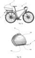
- a two-wheeled vehicle 1 has at its rear end a luggage rack bracket 2 to which a trunk 3 can be attached.
- the trunk is provided with means for transporting the trunk in a separate condition from the vehicle; in a preferred embodiment, the trunk is provided with a handle 13 positioned in the upper part of the half shell 103 which, in addition to being used for transport, may serve for opening the trunk and for engagement and/or disengagement from the vehicle.
- the trunk 3 may comprise a three-dimensional shell of material that is rigid, soft, but such that it maintains a predetermined three-dimensional shape, or floppy material in the form of a leaf, sheet or similar.
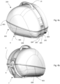
- the three-dimensional trunk shell is divided according to a horizontal or substantially horizontal dividing line 403, i.e. also slightly inclined into two half-shells 103, 203 of which a lower half-shell 103 and an upper half-shell 203.
- the upper half-shell 203 is articulated to the lower half-shell by means of articulation means, such as a hinge shown or comprising a jumper of piece material with one or both half-shells.
- the articulation is provided along a segment of the separation line 603, shown in figure a, which is provided substantially along the front side of the trunk 3 with reference to the condition fitted to the vehicle 1.
- the remaining segment of the separation line 403 extends from either end of the joint line 603 of the two half shells 103, 203 to each other.
- Hinging along the line of articulation 603 or along part of it is intended to open the trunk which is done by rotation between the two shells and is achieved, for example, by mechanical members such as one or more hinges arranged along the line of articulation 603.
- Removable means of connection of the two half-shells 103, 203 can be provided along the separation line 403, which can be of any type.
- Said means may comprise, for example, magnetic means extending along the entire separation line 403 and holding the two half-shells against each other with a force that can be overcome by manual action.
- said means may be means for interlocking the two half-shells along said separation line 403, acting along the whole said line or at one or more predetermined points, and which may have actuating members, for controlling in a condition of mutual engagement and disengagement and thus releasing or restraining the two half-shells respectively from each other and against each other.
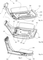
- an interlocking member 4 an embodiment of which is presented in Figures 2a-2c , intended to be fixed by suitable means to the vehicle bracket 2 of the vehicle 1.
- the interlocking member 4 may be anchored to the bracket or carrier 2 of the frame or, when the vehicle does not have such a bracket or in any case the bracket is not suitable for the purpose, the interlocking member 4 may be anchored to the frame by means of an adapter member 6.
- the interlocking member 4 is provided with frame anchoring members (404) such as, for example, a plurality of holes that may be threaded to accommodate joining members to the vehicle frame such as screws and/or bolts.
- the interlocking member 4 cooperates with an attachment member 5 intended to be permanently fixed to the bottom side, i.e. the bottom side of the trunk, i.e. the bottom half shell 103.
- the coupling member 5 is designed to be brought into a position of engagement with the interlocking member (4) by means of a movement also referred to herein as an engagement stroke.
- an engagement stroke At the end of the engagement stroke, the trunk (to which the coupling member is integral) is in a stable position on the frame (to which the interlocking member is integral).
- the release between the trunk and the vehicle comprises a disengagement stroke that releases the trunk from the vehicle allowing the user to remove the trunk, preferably carrying it by the knob 13.
- the interlocking member 4 comprises a plate 204 fixable by screws to the bracket 2 of the vehicle 1 or to the adapter member 6, which plate has an interlocking seat 104 disposed in the front side of the plate itself, with reference to the trunk engagement stroke, and projecting from its upper side.
- the interlocking seat 104 is herein realized in the form of an elongated plate 1104, having two long peripheral edges and two short peripheral edges, arranged in a plane substantially parallel to the plane of the plate and orthogonal to the direction of advancement of the vehicle, supported at the short peripheral edges by two supports 2104.
- the two supports 2104 thus rigidly connect the plate to the plate 4, being able to be made of piece with the plate and/or with the plate.
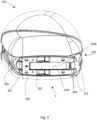
- the coupling member 5 also comprises a plate intended to be fixed to the bottom of the lower half shell 103.
- a plate intended to be fixed to the bottom of the lower half shell 103.
- the plate forming the interlocking member 5 is fixed to a bottom counterplate (not illustrated) which may be provided internally to the lower half-shell 103 along the bottom side thereof or may also constitute a partial cup or partial coating of said bottom side.
- the coupling member 5 carries its coupling teeth 105 in positions coinciding with those of the interlocking seat 104 located in the coupling member 4.
- the positions of the teeth 105 and the interlocking seat 104 are such as to allow mutual engagement and disengagement with a single relative translational movement of the two members 4 and 5 in the direction of the longitudinal axis of the vehicle.
- This swinging lever carries at its free end a lock mechanism 8 which will be described in more detail below.
- the swinging lever 7 is preferably, but not necessarily, associated with an oscillatory motion control mechanism which, advantageously, acts to give uniformity to the movement of the swinging lever itself. This control is more evident in the opening phase where, in most cases, the user does not drive the swinging lever but leaves it free to open under the action of gravity. In this situation, the control mechanism acts by making the opening movement of the swinging lever more uniform and, in particular, the angular speed, avoiding damage and/or rebounds at the end of the swinging lever stroke and, at the same time, making the opening smoother and more pleasant.
- the damping effect is obtained by the combination of a damping member 407 and an elastic member 507.
- An activation/deactivation mechanism 8 is associated with the swinging lever 7, which allows the said lever to be retained in the raised condition of locking the trunk in the condition of engagement of the coupling member 5 in the interlocking member 4.
- Such activation and deactivation mechanisms of the swinging lever can advantageously be controlled by a key lock such as indicated by 18 and can be multiple and simultaneously activated with each other.
- the swinging lever 7 may contextually have the function of holding the two half-shells 103, 203 in the closed condition of the trunk, or also provide protection against unwanted opening of the trunk by protecting the devices that allow separation between the two half-shells 103 and 203.
- the swinging lever 7 in the raised locking condition can operate in a locked position against sliding in the opening direction of the two zip sliders.
- Figures 5a and 5b show, respectively, the components located at the end of the swinging lever 7 and of the trunk according to the embodiment presented herein, which is preferred but not limiting to the invention.
- the tang 508 is further provided with an appendage 2508, which guides and controls the retaining hook 408 and prevents it from moving or not.
- the retaining hook 408 is oscillatingly mounted on a cylindrical support 608, which support 608 also acts as a pivot-guide for a helical spring 108 ( figure 6 ) whose elastic force acts on the hook 408 forcing it into a raised position.
- the tang 508 is shown in the unlocked condition and the appendage 2508 does not interfere with the retaining hook 408.
- pressing the button 208 by a user results in a force opposing the elastic force of the spring 108 and, depending on its intensity, in rotation of the hook 408 around the pin 608 resulting in downward displacement of the unrestrained end of the hook itself.
- Rotation of the hook 408 leads to release from the pin 509 and consequently to release of the swinging lever 7 from the three-dimensional shell of the trunk, with the swinging lever free to swing and move into the open position.
- the mutual engagement means between the swinging lever 7 and the trunk comprise a retractable member, also activated by the key mechanism by means of the appendage 1508 of the tang 508, articulated to make an excursion in the direction of the half shell and engage a corresponding locking seat 39.
- the engagement of said retractable member in the seat increases the locking power between the swinging lever and the trunk, in addition to what is already offered by the hook 408.
- the retractable member comprises a rod 308, cylindrical in shape, disposed on the swinging lever 7 and oriented in a direction substantially tangential to the oscillatory path of said locking member around said swing axis, said rod 308 being intended to be received by a slotted body 309 positioned on the half-shell 203 of the trunk in a plane orthogonal to said rod when the condition of engagement of the mutual engagement means occurs.
- the slotted body 309 has a coupling opening 409 having a shape and size substantially equal to the cylindrical sectional shape of the rod 308.
- the combined action of the pin and the slot has the advantageous effect of centring the engagement body and, when engaged, limiting the reciprocal movement of the swinging lever end by preventing misalignment or undesirable movement.
- the swinging lever 7 When not engaged to the trunk, the swinging lever 7 can be retracted to the closed position by placing the free end interlocked with the plate 204, which plate 204 comprises an opening and a resting engagement member 704 arranged to be engaged with the hook 408 of the swinging lever 7. This makes it safer to drive the vehicle without a trunk and prevents damage due to free swinging of the lever subject to the vibrations and shocks of vehicle movement.
- the engagement position is shown in figure 6 , where some components have been omitted to facilitate the representation of the engagement state.
- the hook 408 cooperating with the pin 509 is shown, where the hook is supported by a helical spring 108 to hold the hook in a raised position and facilitate the engagement operation.
- the force of the spring is counteracted by any pressure exerted on the button when it is intended to disengage the trunk, and downward movement of the hook 408 is permitted or not permitted depending on the position of the lock and tang 508.
- Figures 5a and 5b further show a further hooked body 708 provided for engagement in a corresponding engagement seat disposed on the upper half shell 203 of the trunk.
- the hooked body 708 is made of piece with the rod 308, translates integral with it under the action of the tang 508 and introduces a further locking action for maintaining the swinging lever in a engaged state.
- the body protrudes at the bottom of the hook and is arranged to interact directly with the appendage 1508 so as to translate towards the trunk when actuated by the rotational motion of the appendage itself.
- the swinging lever 7 may have corresponding engagement members of the slider(s) of the zip(s) connecting the two half-shells 103, 203 to each other and in particular of the gripping tabs of the zip sliders.
- a further characterising aspect of the present invention is related to the presence, in an executive and non-limiting form, of further controlled locking members which act when the swinging lever 7 is in the upward tilted position and are activated and deactivated simultaneously with the movement of the swinging lever during displacement towards the locking position (upward tilted position) and during displacement towards the position of non-interference with the shell, respectively.
- two projections 307 ( figure 2 ) are provided at the base of the swinging lever 7 according to an arrangement in two planes orthogonal to the swing axis of the swinging lever and are inserted in corresponding grooves 305 obtained in the rear part of the base of the lower half shell 103, preferably in the coupling member 5.
- the two projections are substantially flat in shape, parallel to each other and spaced apart by a predetermined distance which may vary according to the embodiments, just as the number of said projections 307 integrated in the swinging lever 7 may freely vary without prejudice to the scope of the invention.
- the dimensioning of the projections 307 and the grooves 305 is such that, during insertion, a force is generated in the direction of the engagement stroke between the plates, which contributes to reaching the stop position of the hooking teeth 105 in the seat 104.
- the hooks exert a second calibrated and predetermined force to hold said coupling member 5 in the engagement position with the interlocking member 4.
- the flat conformation of the projections 307 has two faces that cooperate with similar surfaces present in the grooves 305 and prevent the trunk from translating horizontally along an axis transverse to the engagement/disengagement stroke.
- the projections 307 may have an appendage 1307 which, when engaged with the trunk, engages corresponding indentations created in the grooves 305 so as to constitute an impediment to movement of the engagement member, i.e., the trunk, along a direction orthogonal to the engagement member 4 i.e., along an upward or downward direction.
- FIG. 7a shows a possible implementation form of an adaptation device as an object of the invention, comprising a support zone 106 and one or more support and/or anchoring zones 206 mirroring the anchoring members 404 present in the interlocking member 4.
Landscapes
- Engineering & Computer Science (AREA)
- Mechanical Engineering (AREA)
- Vehicle Step Arrangements And Article Storage (AREA)
- Lock And Its Accessories (AREA)
- Purses, Travelling Bags, Baskets, Or Suitcases (AREA)
Claims (19)
- Vorrichtung zum Aufbewahren von Gegenständen (3) für Grätschsitz-Zweiradfahrzeuge, wie ein Fahrrad, ein Motorrad, umfassend:- einen Koffer, der eine in sich geschlossene und vorzugsweise zumindest teilweise aus mindestens einem weichen und flexiblen Material hergestellte dreidimensionale Schale umfasst, die einen Aufnahmeraum begrenzt und durch zwei sich unter Bildung der dreidimensionalen Schale gegenseitig ergänzende Schalenteile (103, 203) gebildet wird, wobei die mindestens zwei Schalenteile durch eine Trennlinie (403) voneinander getrennt sind, die sich von einem Ende zum anderen Ende eines die beiden Schalenteile gelenkig miteinander verbindenden Scharnierabschnitts (603) derart erstreckt, dass die beiden Schalenteile (103, 203) in einer offenen Stellung der dreidimensionalen Schale oder in einer geschlossenen Stellung der dreidimensionalen Schale jeweils voneinander wegbewegt und einander angenähert werden können, und wobei Mittel zum lösbaren Festhalten der beiden Schalenteile aneinander in der geschlossenen Stellung der dreidimensionalen Schale vorgesehen sind,- lösbare Befestigungsmittel der dreidimensionalen Schale an einem Strukturteil (2) eines Grätschsitz-Zweiradfahrzeugs, wobei die Mittel mindestens ein zur dauerhaften Befestigung an dem Strukturteil (2) eines Grätschsitz-Zweiradfahrzeugs bestimmtes Verriegelungselement (4) und ein Kopplungselement (5) umfassen, das mit einem der beiden Schalenteile (103, 203) gebunden ist und das durch eine Relativbewegung entlang eines Eingriffs- /Freigabehubes gemäß einem vorbestimmten Weg mit dem Verriegelungselement (4) in Eingriff und außer Eingriff gebracht werden kann, wobei ein zweites Verriegelungselement zum Verriegeln des Kupplungselements (5) mit dem Verriegelungselement (4) in einer Eingriffsposition vorgesehen ist, wobei das zweite Verriegelungselement einen Schwenkhebel (7) umfasst, der schwenkbar an dem Verriegelungselement (4) angebracht ist und um eine quer zur Richtung des Eingriffs-/Freigabehubs ausgerichtete Schwenkachse schwenkt, wobei der Schwenkhebel (7) am oder in der Nähe des hinteren Endes des Verriegelungselements (4) in Bezug auf die Richtung des Eingriffshubs des Kupplungselements (5) in dem Verriegelungselement (4) angeordnet ist, wobei der Schwenkhebel (7) wechselweise winkelbeweglich ist:- in einer Nicht-Interferenzposition mit der dreidimensionalen Schale (103, 203), wenn er mit dem Verriegelungselement (4) in Eingriff steht, wobei das Kupplungselement (5) und daher die Schale (103, 203) zusammen auf dem Verriegelungselement (4) entlang des Eingriffs-/Freigabehubs beweglich sind oder- in einer Interferenzposition mit der dreidimensionalen Schale (103, 203), wobei der Schwenkhebel (7) nach oben gegen die Rückseite der dreidimensionalen Schale gekippt ist, wobei die Interferenzposition des Schwenkhebels (7) einen Anschlag für die freie Verschiebung der dreidimensionalen Schale und folglich des Kupplungselements (5) in der Richtung des Lösens von dem Verriegelungselement (4) darstellt,wobei das mit einem der beiden Schalenteile (103, 203) einstückige Kupplungselement (5) mindestens ein weiteres zweites Kupplungselement (105), vorzugsweise zwei oder möglicherweise mehr als zwei weitere zweite Kupplungselemente (105), umfasst, die gemäß einem vorbestimmten Design entlang einer Achse im Wesentlichen quer zur Richtung des Eingriffs-/Freigabehubs verteilt und im vorderen Teil des Kupplungselements (5) positioniert sind, während das Verriegelungselement (4) mit einem Verriegelungssitz (104) versehen ist, der zum Zusammenwirken mit den weiteren zweiten Kopplungselementen (105) geeignet und im vorderen Teil des Verriegelungselements (4) angeordnet ist, wobei der Verriegelungssitz (104) durch die weiteren zweiten Kopplungselemente (105) mittels einer Verschiebung in einer im Wesentlichen horizontalen oder leicht geneigten Ebene in Eingriff und außer Eingriff gebracht wird,dadurch gekennzeichnet, dasswenn sich der Schwenkhebel (7) in der Interferenzposition mit der auf dem Verriegelungselement (4) installierten dreidimensionalen Schale (103, 203) befindet, der Schwenkhebel (7) sich so erstreckt, dass er zumindest teilweise den nicht direkt mit dem Kupplungselement (5) verbundenen Teil der Schale (103, 203) überlappt und mit diesem in Eingriff kommt und verriegelt.
- Vorrichtung nach Anspruch 1, wobei der Verriegelungssitz (104) mit Endanschlagmitteln (304) versehen ist, die mit den Kupplungselementen (105) zusammenwirken, um den Eingriffshub zu stoppen und das Eingriffselement mit dem Verriegelungselement in einer verriegelten Position zu verbinden, wobei andere Bewegungen als die Bewegung des Freigabehubs verhindert werden.
- Vorrichtung nach Anspruch 1 oder 2, wobei das Verriegelungselement (4) und das Kupplungselement (5) mit zusammenwirkenden Führungsmitteln (604) in einer Position der gegenseitigen Zentrierung und des relativen Gleitens in der Eingriffs- /Freigaberichtung zwischen dem Verriegelungselement (4) und dem Kupplungselement (5) versehen sind.
- Vorrichtung nach einem oder mehreren der vorhergehenden Ansprüche, wobei die weiteren zweiten Kupplungselemente mindestens einen Eingriffszahn umfassen, der in einer horizontalen oder leicht geneigten Ebene angeordnet und in Richtung des Eingriffshubs ausgerichtet ist, während der Eingriffssitz (104) mindestens eine längliche Oberplatte (1104) umfasst, die quer zur Richtung des Eingriffs-/Freigabehubs angeordnet ist und zwei lange Umfangsränder und zwei kurze Umfangsränder aufweist, wobei die Platte (1104) an ihren kurzen Umfangsrändern von zwei vertikalen Halterungen (2104) getragen wird, die mit dem Eingriffszahn oder den Eingriffszähnen zusammenwirken, um eine Querbewegung des Kupplungselements (5) zu verhindern, wenn es sich in Eingriffsposition mit dem Verriegelungselement (4) befindet.
- Vorrichtung nach einem oder mehreren der vorhergehenden Ansprüche, wobei die weiteren zweiten Kupplungselemente zum Verriegeln des Kupplungselements (5) mit dem Verriegelungselement (4) weitere angetriebene Verriegelungselemente (307) umfassen, die in der nach oben gekippten Position des Verriegelungselements wirken und sich mit diesem gleichzeitig aktivieren und deaktivieren, wobei sie in Richtung des Eingriffshubs wirken und mit entsprechenden in das Kupplungselement (5) geschnittenen Nuten (305) derart zusammenwirken, dass eine kalibrierte und vorbestimmte Haltekraft auf das Kupplungselement (5) in der Eingriffsposition mit dem Verriegelungselement (4) ausgeübt wird, die zumindest die Längs- und Querverschiebung des Kupplungselements (5) in Bezug auf das Verriegelungselement (4) verhindert.
- Vorrichtung nach einem oder mehreren der vorhergehenden Ansprüche, wobei der Schwenkhebel (7) einen Schwingungsbewegungssteuerungsmechanismus umfasst, vorzugsweise in Form eines Winkelgeschwindigkeitsdämpfungsmechanismus mittels mindestens eines Bewegungsverzögerers (407), der in der Nähe der Schwenkachse angeordnet ist, um die der Schwenkhebel (7) schwingt, wobei der Schwingungsbewegungssteuerungsmechanismus optional ein weiteres elastisches Aktivierungselement (507) der Schwingungsbewegung umfasst.
- Vorrichtung nach einem oder mehreren der vorhergehenden Ansprüche, dadurch gekennzeichnet, dass die Verriegelungsmittel durch einen Aktivierungs-/Deaktivierungsmechanismus (8, 9) aktiviert oder deaktiviert werden, der ein Schlüsselschloss (18) umfasst, das dazu bestimmt ist, mit einem Verriegelungssitz (39) zusammenzuwirken.
- Vorrichtung nach Anspruch 7, wobei der Aktivierungs-/Deaktivierungsmechanismus (8, 9) Rückhaltemittel (408, 509) des Verriegelungselements in der Interferenzposition gegen die Rückseite der dreidimensionalen Schale umfasst, wobei die Rückhaltemittel (408, 409) in der Aktivierungs- und/oder Deaktivierungsposition mittels eines Druckmechanismus (208) betätigt werden können, dessen Funktionsfähigkeit an das Schlüsselschloss (18) gebunden ist.
- Vorrichtung nach einem oder mehreren der vorhergehenden Ansprüche, dadurch gekennzeichnet, dass zumindest der Teil der Schale (203), der nicht das Kupplungselement (5) und den Schwenkhebel trägt, den Aktivierungs/Deaktivierungsmechanismus (8, 9) aufnimmt.
- Vorrichtung nach einem oder mehreren der Ansprüche 7 bis 9, wobei der (Aktivierungs-/Deaktivierungs-)Mechanismus (8, 9) in der Eingriffsstellung durch ein oder mehrere elastische Elemente (108) gehalten wird, die durch einen Druckmechanismus (208) zum Entriegeln des Aktivierungs-/Deaktivierungsmechanismus (8, 9) in der Eingriffsstellung gesteuert werden.
- Vorrichtung nach einem oder mehreren der vorhergehenden Ansprüche 7 bis 10, wobei der Aktivierungs-/Deaktivierungsmechanismus (8, 9) eine vorzugsweise zylinderförmige Stange (308) umfasst, die auf dem Schwenkhebel (7) angeordnet und entlang einer Richtung ausgerichtet ist, die im Wesentlichen tangential zum Schwingungsweg des Schwenkhebels (7) um die Schwenkachse verläuft, wobei die Stange (308) dazu bestimmt ist, von einem geschlitzten Körper (309) aufgenommen zu werden, der auf einer Halbschale (203) des Koffers in einer Ebene orthogonal zu der Stange positioniert ist, wenn der Eingriffszustand des Aktivierungs-/Deaktivierungsmechanismus (8, 9) vorliegt, wobei der geschlitzte Körper (309) eine Kupplungsöffnung (409) umfasst, die eine Form und Größe aufweist, die im Wesentlichen gleich der zylindrischen Querschnittsform der Stange (308) ist, um die Stange (308) aufzunehmen.
- Vorrichtung nach einem oder mehreren der vorhergehenden Ansprüche 7 bis 11, wobei der Aktivierungs-/Deaktivierungsmechanismus (8, 9) ein hakenförmiges Element (708) umfasst, das an dem Schwenkhebel (7) angeordnet und zum Eingriff in einen an der oberen Halbschale (203) des Koffers angeordneten entsprechenden Eingriffssitz vorgesehen ist, wobei das hakenförmige Element (708) mit einem Ansatz (1508) des Aktivierungs- /Deaktivierungselements zur Verschiebung in Position von mindestens einem der Halteelemente (308) zusammenwirkt.
- Vorrichtung nach einem oder mehreren der vorhergehenden Ansprüche, wobei die beiden Schalenteile (103, 203) entlang der Trennlinie (403) mittels eines Reißverschlusses miteinander verbindbar sind, der mindestens einen Griff und mindestens einen Schieber umfasst, wobei der Reißverschluss so vorgesehen ist, dass im geschlossenen Zustand der Griff und der Schieber so vorgesehen sind, dass sie in der Nähe des freien Endes (8) der Verriegelungsvorrichtung angeordnet sind, die in der Eingriffsstellung zusammen mit einem Teil der Schale einen geschlossenen Bereich definiert, um den Zugang und die Betätigung des Griffs und des Schiebers durch eine Bedienungsperson zu schützen.
- Vorrichtung nach einem oder mehreren der vorhergehenden Ansprüche, dadurch gekennzeichnet, dass das Kupplungselement (5) eine Kupplungsplatte (205) umfasst, die einen oder mehrere Kupplungszähne (105) aufweist, die von ihrem vorderen Profil in Bezug auf den Eingriffshub in dem Verriegelungselement (4) vorstehen, wobei die Eingriffsplatte (205) ferner eine, vorzugsweise zwei oder alternativ mehr als zwei Nuten (305) in der Nähe ihres hinteren Profils in Bezug auf den Eingriffshub in dem Verriegelungselement (4) aufweist, und wobei die Eingriffsplatte (205) an der Wand eines der beiden Schalenteile (103) befestigbar ist.
- Vorrichtung nach einem oder mehreren der vorhergehenden Ansprüche, dadurch gekennzeichnet, dass das Verriegelungselement (4) eine Verriegelungsplatte (204) umfasst, die die obere Platte (1104) und die vertikalen Halterungen im vorderen Bereich in Bezug auf den Eingriffshub durch das Kopplungselement (5) aufnimmt, wobei die Platte (204) ferner an ihrem hinteren Ende mit dem Schwenkhebel (7) verbunden ist, der schwenkbar um eine quer zum Eingriffshub verlaufende Schwenkachse angebracht ist, wobei die Verriegelungsplatte mit Verankerungselementen am Rahmen (404) des Zweiradfahrzeugs versehen ist.
- Vorrichtung nach einem oder mehreren der vorhergehenden Ansprüche, dadurch gekennzeichnet, dass sie eine Rahmenanpassungsvorrichtung (6) umfasst, die dazu bestimmt ist, auf einstellbare und abnehmbare Weise an einem oder mehreren Teilen des Rahmens des Zweiradfahrzeugs befestigt zu werden, und die einen Stützbereich (106) und einen oder mehrere Stütz- und/oder Verankerungsbereiche (206) für die in dem Verriegelungselement (4) ausgebildeten Verankerungselemente (404) umfasst.
- Vorrichtung nach Anspruch 16, wobei die Rahmenanpassungsvorrichtung mindestens ein oder mehrere manuell einstellbare Gelenke (306) umfasst, um den Stützbereich um eine oder mehrere Schwenkachsen zu schwenken und/oder entlang einer oder mehrerer Verschiebeachsen in Übereinstimmung mit der gewünschten Ausrichtung des Koffers in der Eingriffsposition zu verschieben.
- Vorrichtung nach Anspruch 16 oder 17, wobei die Rahmenanpassungsvorrichtung (6) mit einem oder mehreren der Verriegelungselemente (4), vorzugsweise aber nicht einschränkend mit der Verriegelungsplatte (204), einstückig ausgebildet ist.
- Vorrichtung nach einem oder mehreren der vorhergehenden Ansprüche 16 bis 18, wobei die Anpassungsvorrichtung (6) einen oder mehrere Klemmkörper (406) zum Festklemmen an zylindrischen Teilen des Rahmens (2) des Zweiradfahrzeugs (1) umfasst.
Applications Claiming Priority (1)
| Application Number | Priority Date | Filing Date | Title |
|---|---|---|---|
| IT102020000028067A IT202000028067A1 (it) | 2020-11-23 | 2020-11-23 | Bauletto amovibile per veicoli a due ruote o simili |
Publications (3)
| Publication Number | Publication Date |
|---|---|
| EP4001075A1 EP4001075A1 (de) | 2022-05-25 |
| EP4001075C0 EP4001075C0 (de) | 2024-07-24 |
| EP4001075B1 true EP4001075B1 (de) | 2024-07-24 |
Family
ID=74557122
Family Applications (1)
| Application Number | Title | Priority Date | Filing Date |
|---|---|---|---|
| EP21209824.8A Active EP4001075B1 (de) | 2020-11-23 | 2021-11-23 | Box für zweirädrige fahrzeuge oder dergleichen |
Country Status (2)
| Country | Link |
|---|---|
| EP (1) | EP4001075B1 (de) |
| IT (1) | IT202000028067A1 (de) |
Family Cites Families (4)
| Publication number | Priority date | Publication date | Assignee | Title |
|---|---|---|---|---|
| JPS5758568A (en) * | 1980-09-22 | 1982-04-08 | Honda Motor Co Ltd | Locking device for upper section of car body, such as seat or rear box or the like of autobicycle |
| DE9007222U1 (de) * | 1990-06-29 | 1990-09-06 | Schroll, Stefan, Dipl.-Ing. (FH), 8221 Nußdorf | Halteelement als Diebstahleinrichtung an Fahrrädern |
| JP2001354178A (ja) * | 2000-06-14 | 2001-12-25 | Ogk Co Ltd | 車用バスケットの装着構造 |
| JP3227762U (ja) * | 2020-06-11 | 2020-09-17 | 株式会社東京錠前製作所 | 自転車用キャリーカート |
-
2020
- 2020-11-23 IT IT102020000028067A patent/IT202000028067A1/it unknown
-
2021
- 2021-11-23 EP EP21209824.8A patent/EP4001075B1/de active Active
Also Published As
| Publication number | Publication date |
|---|---|
| EP4001075C0 (de) | 2024-07-24 |
| IT202000028067A1 (it) | 2022-05-23 |
| EP4001075A1 (de) | 2022-05-25 |
Similar Documents
| Publication | Publication Date | Title |
|---|---|---|
| US7997591B2 (en) | Chassis with retractable wheels | |
| EP2133180B1 (de) | Werkzeugbehälteranordnung | |
| CA2465806C (en) | Vehicle hitch rack | |
| US7547054B2 (en) | Vehicle cargo bed extender | |
| US5024359A (en) | Bicycle cooler | |
| TWI812956B (zh) | 具輔助籃的可轉換兒童推車系統 | |
| US6811198B2 (en) | System for storing a load in a vehicle | |
| EP2907494A1 (de) | Tisch für rollstuhl und rollstuhl damit | |
| CN112078449B (zh) | 儿童安全座椅以及其系带 | |
| DK2168854T3 (en) | A fastening system for bags or containers | |
| CN114025994B (zh) | 负载承载架 | |
| EP4001075B1 (de) | Box für zweirädrige fahrzeuge oder dergleichen | |
| EP1963136B1 (de) | Lastvorrichtung für fahrzeuge | |
| US20220089068A1 (en) | Child safety seat with energy absorber | |
| JP6594709B2 (ja) | 車両用フック装置 | |
| EP3683127A1 (de) | Box für motorrad | |
| EP3277564B1 (de) | Einrücksystem | |
| KR102018041B1 (ko) | 보조 체인 바퀴부를 포함하는 여행용 가방 | |
| NL2007674C2 (nl) | Aangrijporgaan voor bevestiging van een houder aan een fietsbagagedrager. | |
| EP4480756B1 (de) | Anordnungen zur befestigung eines ladungsträgers an einem ladungsträger | |
| KR20210131681A (ko) | 서랍 고정장치 | |
| JP2005262980A (ja) | 補助具取付装置 | |
| KR101756872B1 (ko) | 자전거에 설치되는 안전기능을 갖는 수납장치 | |
| JP6225006B2 (ja) | ペット用キャリー付きカート | |
| AU2026202780A1 (en) | Convertible Child Stroller System with Auxiliary Basket |
Legal Events
| Date | Code | Title | Description |
|---|---|---|---|
| PUAI | Public reference made under article 153(3) epc to a published international application that has entered the european phase |
Free format text: ORIGINAL CODE: 0009012 |
|
| STAA | Information on the status of an ep patent application or granted ep patent |
Free format text: STATUS: THE APPLICATION HAS BEEN PUBLISHED |
|
| AK | Designated contracting states |
Kind code of ref document: A1 Designated state(s): AL AT BE BG CH CY CZ DE DK EE ES FI FR GB GR HR HU IE IS IT LI LT LU LV MC MK MT NL NO PL PT RO RS SE SI SK SM TR |
|
| STAA | Information on the status of an ep patent application or granted ep patent |
Free format text: STATUS: REQUEST FOR EXAMINATION WAS MADE |
|
| 17P | Request for examination filed |
Effective date: 20221117 |
|
| RBV | Designated contracting states (corrected) |
Designated state(s): AL AT BE BG CH CY CZ DE DK EE ES FI FR GB GR HR HU IE IS IT LI LT LU LV MC MK MT NL NO PL PT RO RS SE SI SK SM TR |
|
| GRAP | Despatch of communication of intention to grant a patent |
Free format text: ORIGINAL CODE: EPIDOSNIGR1 |
|
| STAA | Information on the status of an ep patent application or granted ep patent |
Free format text: STATUS: GRANT OF PATENT IS INTENDED |
|
| RIC1 | Information provided on ipc code assigned before grant |
Ipc: B62H 5/00 20060101ALN20240126BHEP Ipc: B62J 9/24 20200101ALI20240126BHEP Ipc: B62J 9/23 20200101AFI20240126BHEP |
|
| INTG | Intention to grant announced |
Effective date: 20240301 |
|
| GRAS | Grant fee paid |
Free format text: ORIGINAL CODE: EPIDOSNIGR3 |
|
| GRAA | (expected) grant |
Free format text: ORIGINAL CODE: 0009210 |
|
| STAA | Information on the status of an ep patent application or granted ep patent |
Free format text: STATUS: THE PATENT HAS BEEN GRANTED |
|
| AK | Designated contracting states |
Kind code of ref document: B1 Designated state(s): AL AT BE BG CH CY CZ DE DK EE ES FI FR GB GR HR HU IE IS IT LI LT LU LV MC MK MT NL NO PL PT RO RS SE SI SK SM TR |
|
| REG | Reference to a national code |
Ref country code: GB Ref legal event code: FG4D |
|
| REG | Reference to a national code |
Ref country code: CH Ref legal event code: EP |
|
| REG | Reference to a national code |
Ref country code: IE Ref legal event code: FG4D Ref country code: DE Ref legal event code: R096 Ref document number: 602021016076 Country of ref document: DE |
|
| U01 | Request for unitary effect filed |
Effective date: 20240809 |
|
| U07 | Unitary effect registered |
Designated state(s): AT BE BG DE DK EE FI FR IT LT LU LV MT NL PT SE SI Effective date: 20240827 |
|
| U20 | Renewal fee for the european patent with unitary effect paid |
Year of fee payment: 4 Effective date: 20241024 |
|
| PG25 | Lapsed in a contracting state [announced via postgrant information from national office to epo] |
Ref country code: NO Free format text: LAPSE BECAUSE OF FAILURE TO SUBMIT A TRANSLATION OF THE DESCRIPTION OR TO PAY THE FEE WITHIN THE PRESCRIBED TIME-LIMIT Effective date: 20241024 |
|
| PG25 | Lapsed in a contracting state [announced via postgrant information from national office to epo] |
Ref country code: PL Free format text: LAPSE BECAUSE OF FAILURE TO SUBMIT A TRANSLATION OF THE DESCRIPTION OR TO PAY THE FEE WITHIN THE PRESCRIBED TIME-LIMIT Effective date: 20240724 Ref country code: GR Free format text: LAPSE BECAUSE OF FAILURE TO SUBMIT A TRANSLATION OF THE DESCRIPTION OR TO PAY THE FEE WITHIN THE PRESCRIBED TIME-LIMIT Effective date: 20241025 |
|
| PG25 | Lapsed in a contracting state [announced via postgrant information from national office to epo] |
Ref country code: IS Free format text: LAPSE BECAUSE OF FAILURE TO SUBMIT A TRANSLATION OF THE DESCRIPTION OR TO PAY THE FEE WITHIN THE PRESCRIBED TIME-LIMIT Effective date: 20241124 |
|
| PG25 | Lapsed in a contracting state [announced via postgrant information from national office to epo] |
Ref country code: HR Free format text: LAPSE BECAUSE OF FAILURE TO SUBMIT A TRANSLATION OF THE DESCRIPTION OR TO PAY THE FEE WITHIN THE PRESCRIBED TIME-LIMIT Effective date: 20240724 |
|
| PG25 | Lapsed in a contracting state [announced via postgrant information from national office to epo] |
Ref country code: RS Free format text: LAPSE BECAUSE OF FAILURE TO SUBMIT A TRANSLATION OF THE DESCRIPTION OR TO PAY THE FEE WITHIN THE PRESCRIBED TIME-LIMIT Effective date: 20241024 Ref country code: ES Free format text: LAPSE BECAUSE OF FAILURE TO SUBMIT A TRANSLATION OF THE DESCRIPTION OR TO PAY THE FEE WITHIN THE PRESCRIBED TIME-LIMIT Effective date: 20240724 |
|
| PG25 | Lapsed in a contracting state [announced via postgrant information from national office to epo] |
Ref country code: RS Free format text: LAPSE BECAUSE OF FAILURE TO SUBMIT A TRANSLATION OF THE DESCRIPTION OR TO PAY THE FEE WITHIN THE PRESCRIBED TIME-LIMIT Effective date: 20241024 Ref country code: PL Free format text: LAPSE BECAUSE OF FAILURE TO SUBMIT A TRANSLATION OF THE DESCRIPTION OR TO PAY THE FEE WITHIN THE PRESCRIBED TIME-LIMIT Effective date: 20240724 Ref country code: NO Free format text: LAPSE BECAUSE OF FAILURE TO SUBMIT A TRANSLATION OF THE DESCRIPTION OR TO PAY THE FEE WITHIN THE PRESCRIBED TIME-LIMIT Effective date: 20241024 Ref country code: IS Free format text: LAPSE BECAUSE OF FAILURE TO SUBMIT A TRANSLATION OF THE DESCRIPTION OR TO PAY THE FEE WITHIN THE PRESCRIBED TIME-LIMIT Effective date: 20241124 Ref country code: HR Free format text: LAPSE BECAUSE OF FAILURE TO SUBMIT A TRANSLATION OF THE DESCRIPTION OR TO PAY THE FEE WITHIN THE PRESCRIBED TIME-LIMIT Effective date: 20240724 Ref country code: GR Free format text: LAPSE BECAUSE OF FAILURE TO SUBMIT A TRANSLATION OF THE DESCRIPTION OR TO PAY THE FEE WITHIN THE PRESCRIBED TIME-LIMIT Effective date: 20241025 Ref country code: ES Free format text: LAPSE BECAUSE OF FAILURE TO SUBMIT A TRANSLATION OF THE DESCRIPTION OR TO PAY THE FEE WITHIN THE PRESCRIBED TIME-LIMIT Effective date: 20240724 |
|
| PG25 | Lapsed in a contracting state [announced via postgrant information from national office to epo] |
Ref country code: RO Free format text: LAPSE BECAUSE OF FAILURE TO SUBMIT A TRANSLATION OF THE DESCRIPTION OR TO PAY THE FEE WITHIN THE PRESCRIBED TIME-LIMIT Effective date: 20240724 Ref country code: SM Free format text: LAPSE BECAUSE OF FAILURE TO SUBMIT A TRANSLATION OF THE DESCRIPTION OR TO PAY THE FEE WITHIN THE PRESCRIBED TIME-LIMIT Effective date: 20240724 |
|
| PG25 | Lapsed in a contracting state [announced via postgrant information from national office to epo] |
Ref country code: CZ Free format text: LAPSE BECAUSE OF FAILURE TO SUBMIT A TRANSLATION OF THE DESCRIPTION OR TO PAY THE FEE WITHIN THE PRESCRIBED TIME-LIMIT Effective date: 20240724 |
|
| PG25 | Lapsed in a contracting state [announced via postgrant information from national office to epo] |
Ref country code: SK Free format text: LAPSE BECAUSE OF FAILURE TO SUBMIT A TRANSLATION OF THE DESCRIPTION OR TO PAY THE FEE WITHIN THE PRESCRIBED TIME-LIMIT Effective date: 20240724 |
|
| PLBE | No opposition filed within time limit |
Free format text: ORIGINAL CODE: 0009261 |
|
| STAA | Information on the status of an ep patent application or granted ep patent |
Free format text: STATUS: NO OPPOSITION FILED WITHIN TIME LIMIT |
|
| 26N | No opposition filed |
Effective date: 20250425 |
|
| PG25 | Lapsed in a contracting state [announced via postgrant information from national office to epo] |
Ref country code: MC Free format text: LAPSE BECAUSE OF FAILURE TO SUBMIT A TRANSLATION OF THE DESCRIPTION OR TO PAY THE FEE WITHIN THE PRESCRIBED TIME-LIMIT Effective date: 20240724 |
|
| PG25 | Lapsed in a contracting state [announced via postgrant information from national office to epo] |
Ref country code: IE Free format text: LAPSE BECAUSE OF NON-PAYMENT OF DUE FEES Effective date: 20241123 |
|
| REG | Reference to a national code |
Ref country code: CH Ref legal event code: U11 Free format text: ST27 STATUS EVENT CODE: U-0-0-U10-U11 (AS PROVIDED BY THE NATIONAL OFFICE) Effective date: 20251215 |
|
| U20 | Renewal fee for the european patent with unitary effect paid |
Year of fee payment: 5 Effective date: 20251128 |
|
| PGFP | Annual fee paid to national office [announced via postgrant information from national office to epo] |
Ref country code: GB Payment date: 20251128 Year of fee payment: 5 |
|
| PGFP | Annual fee paid to national office [announced via postgrant information from national office to epo] |
Ref country code: CH Payment date: 20251215 Year of fee payment: 5 |
|
| PG25 | Lapsed in a contracting state [announced via postgrant information from national office to epo] |
Ref country code: HU Free format text: LAPSE BECAUSE OF FAILURE TO SUBMIT A TRANSLATION OF THE DESCRIPTION OR TO PAY THE FEE WITHIN THE PRESCRIBED TIME-LIMIT; INVALID AB INITIO Effective date: 20211123 |
|
| PG25 | Lapsed in a contracting state [announced via postgrant information from national office to epo] |
Ref country code: CY Free format text: LAPSE BECAUSE OF FAILURE TO SUBMIT A TRANSLATION OF THE DESCRIPTION OR TO PAY THE FEE WITHIN THE PRESCRIBED TIME-LIMIT; INVALID AB INITIO Effective date: 20211123 |