EP4001137A1 - Dispositif de manipulation et procédé de manipulation de matière d'emballage en forme de bande - Google Patents
Dispositif de manipulation et procédé de manipulation de matière d'emballage en forme de bande Download PDFInfo
- Publication number
- EP4001137A1 EP4001137A1 EP20207738.4A EP20207738A EP4001137A1 EP 4001137 A1 EP4001137 A1 EP 4001137A1 EP 20207738 A EP20207738 A EP 20207738A EP 4001137 A1 EP4001137 A1 EP 4001137A1
- Authority
- EP
- European Patent Office
- Prior art keywords
- packaging material
- web
- holding device
- processing station
- handling device
- Prior art date
- Legal status (The legal status is an assumption and is not a legal conclusion. Google has not performed a legal analysis and makes no representation as to the accuracy of the status listed.)
- Granted
Links
Images


Classifications
-
- B—PERFORMING OPERATIONS; TRANSPORTING
- B65—CONVEYING; PACKING; STORING; HANDLING THIN OR FILAMENTARY MATERIAL
- B65B—MACHINES, APPARATUS OR DEVICES FOR, OR METHODS OF, PACKAGING ARTICLES OR MATERIALS; UNPACKING
- B65B41/00—Supplying or feeding container-forming sheets or wrapping material
- B65B41/12—Feeding webs from rolls
- B65B41/14—Feeding webs from rolls by grippers
-
- B—PERFORMING OPERATIONS; TRANSPORTING
- B65—CONVEYING; PACKING; STORING; HANDLING THIN OR FILAMENTARY MATERIAL
- B65B—MACHINES, APPARATUS OR DEVICES FOR, OR METHODS OF, PACKAGING ARTICLES OR MATERIALS; UNPACKING
- B65B41/00—Supplying or feeding container-forming sheets or wrapping material
- B65B41/02—Feeding sheets or wrapper blanks
- B65B41/10—Feeding sheets or wrapper blanks by rollers
-
- B—PERFORMING OPERATIONS; TRANSPORTING
- B65—CONVEYING; PACKING; STORING; HANDLING THIN OR FILAMENTARY MATERIAL
- B65B—MACHINES, APPARATUS OR DEVICES FOR, OR METHODS OF, PACKAGING ARTICLES OR MATERIALS; UNPACKING
- B65B41/00—Supplying or feeding container-forming sheets or wrapping material
- B65B41/02—Feeding sheets or wrapper blanks
- B65B41/04—Feeding sheets or wrapper blanks by grippers
- B65B41/06—Feeding sheets or wrapper blanks by grippers by suction-operated grippers
-
- B—PERFORMING OPERATIONS; TRANSPORTING
- B25—HAND TOOLS; PORTABLE POWER-DRIVEN TOOLS; MANIPULATORS
- B25J—MANIPULATORS; CHAMBERS PROVIDED WITH MANIPULATION DEVICES
- B25J15/00—Gripping heads and other end effectors
- B25J15/06—Gripping heads and other end effectors with vacuum or magnetic holding means
- B25J15/0616—Gripping heads and other end effectors with vacuum or magnetic holding means with vacuum
-
- B—PERFORMING OPERATIONS; TRANSPORTING
- B65—CONVEYING; PACKING; STORING; HANDLING THIN OR FILAMENTARY MATERIAL
- B65B—MACHINES, APPARATUS OR DEVICES FOR, OR METHODS OF, PACKAGING ARTICLES OR MATERIALS; UNPACKING
- B65B11/00—Wrapping, e.g. partially or wholly enclosing, articles or quantities of material, in strips, sheets or blanks, of flexible material
-
- B—PERFORMING OPERATIONS; TRANSPORTING
- B65—CONVEYING; PACKING; STORING; HANDLING THIN OR FILAMENTARY MATERIAL
- B65B—MACHINES, APPARATUS OR DEVICES FOR, OR METHODS OF, PACKAGING ARTICLES OR MATERIALS; UNPACKING
- B65B41/00—Supplying or feeding container-forming sheets or wrapping material
- B65B41/12—Feeding webs from rolls
- B65B41/16—Feeding webs from rolls by rollers
-
- B—PERFORMING OPERATIONS; TRANSPORTING
- B65—CONVEYING; PACKING; STORING; HANDLING THIN OR FILAMENTARY MATERIAL
- B65B—MACHINES, APPARATUS OR DEVICES FOR, OR METHODS OF, PACKAGING ARTICLES OR MATERIALS; UNPACKING
- B65B41/00—Supplying or feeding container-forming sheets or wrapping material
- B65B41/18—Registering sheets, blanks, or webs
-
- B—PERFORMING OPERATIONS; TRANSPORTING
- B65—CONVEYING; PACKING; STORING; HANDLING THIN OR FILAMENTARY MATERIAL
- B65B—MACHINES, APPARATUS OR DEVICES FOR, OR METHODS OF, PACKAGING ARTICLES OR MATERIALS; UNPACKING
- B65B65/00—Details peculiar to packaging machines and not otherwise provided for; Arrangements of such details
- B65B65/003—Packaging lines, e.g. general layout
-
- B—PERFORMING OPERATIONS; TRANSPORTING
- B65—CONVEYING; PACKING; STORING; HANDLING THIN OR FILAMENTARY MATERIAL
- B65H—HANDLING THIN OR FILAMENTARY MATERIAL, e.g. SHEETS, WEBS, CABLES
- B65H20/00—Advancing webs
- B65H20/16—Advancing webs by web-gripping means, e.g. grippers, clips
-
- B—PERFORMING OPERATIONS; TRANSPORTING
- B65—CONVEYING; PACKING; STORING; HANDLING THIN OR FILAMENTARY MATERIAL
- B65H—HANDLING THIN OR FILAMENTARY MATERIAL, e.g. SHEETS, WEBS, CABLES
- B65H23/00—Registering, tensioning, smoothing or guiding webs
- B65H23/02—Registering, tensioning, smoothing or guiding webs transversely
- B65H23/022—Registering, tensioning, smoothing or guiding webs transversely by tentering devices
-
- B—PERFORMING OPERATIONS; TRANSPORTING
- B65—CONVEYING; PACKING; STORING; HANDLING THIN OR FILAMENTARY MATERIAL
- B65H—HANDLING THIN OR FILAMENTARY MATERIAL, e.g. SHEETS, WEBS, CABLES
- B65H5/00—Feeding articles separated from piles; Feeding articles to machines
- B65H5/08—Feeding articles separated from piles; Feeding articles to machines by grippers, e.g. suction grippers
- B65H5/14—Details of grippers; Actuating-mechanisms therefor
-
- B—PERFORMING OPERATIONS; TRANSPORTING
- B65—CONVEYING; PACKING; STORING; HANDLING THIN OR FILAMENTARY MATERIAL
- B65H—HANDLING THIN OR FILAMENTARY MATERIAL, e.g. SHEETS, WEBS, CABLES
- B65H2301/00—Handling processes for sheets or webs
- B65H2301/50—Auxiliary process performed during handling process
- B65H2301/52—Auxiliary process performed during handling process for starting
- B65H2301/522—Threading web into machine
-
- B—PERFORMING OPERATIONS; TRANSPORTING
- B65—CONVEYING; PACKING; STORING; HANDLING THIN OR FILAMENTARY MATERIAL
- B65H—HANDLING THIN OR FILAMENTARY MATERIAL, e.g. SHEETS, WEBS, CABLES
- B65H2404/00—Parts for transporting or guiding the handled material
- B65H2404/50—Surface of the elements in contact with the forwarded or guided material
- B65H2404/51—Cross section, i.e. section perpendicular to the direction of displacement
- B65H2404/511—Cross section, i.e. section perpendicular to the direction of displacement convex
-
- B—PERFORMING OPERATIONS; TRANSPORTING
- B65—CONVEYING; PACKING; STORING; HANDLING THIN OR FILAMENTARY MATERIAL
- B65H—HANDLING THIN OR FILAMENTARY MATERIAL, e.g. SHEETS, WEBS, CABLES
- B65H2406/00—Means using fluid
- B65H2406/30—Suction means
- B65H2406/34—Suction grippers
- B65H2406/342—Suction grippers being reciprocated in a rectilinear path
-
- B—PERFORMING OPERATIONS; TRANSPORTING
- B65—CONVEYING; PACKING; STORING; HANDLING THIN OR FILAMENTARY MATERIAL
- B65H—HANDLING THIN OR FILAMENTARY MATERIAL, e.g. SHEETS, WEBS, CABLES
- B65H2406/00—Means using fluid
- B65H2406/30—Suction means
- B65H2406/34—Suction grippers
- B65H2406/343—Details of sucking member
-
- B—PERFORMING OPERATIONS; TRANSPORTING
- B65—CONVEYING; PACKING; STORING; HANDLING THIN OR FILAMENTARY MATERIAL
- B65H—HANDLING THIN OR FILAMENTARY MATERIAL, e.g. SHEETS, WEBS, CABLES
- B65H2406/00—Means using fluid
- B65H2406/30—Suction means
- B65H2406/34—Suction grippers
- B65H2406/343—Details of sucking member
- B65H2406/3432—Elongated sucking member; Sucking bar
-
- B—PERFORMING OPERATIONS; TRANSPORTING
- B65—CONVEYING; PACKING; STORING; HANDLING THIN OR FILAMENTARY MATERIAL
- B65H—HANDLING THIN OR FILAMENTARY MATERIAL, e.g. SHEETS, WEBS, CABLES
- B65H2406/00—Means using fluid
- B65H2406/30—Suction means
- B65H2406/35—Other elements with suction surface, e.g. plate or wall
- B65H2406/351—Other elements with suction surface, e.g. plate or wall facing the surface of the handled material
-
- B—PERFORMING OPERATIONS; TRANSPORTING
- B65—CONVEYING; PACKING; STORING; HANDLING THIN OR FILAMENTARY MATERIAL
- B65H—HANDLING THIN OR FILAMENTARY MATERIAL, e.g. SHEETS, WEBS, CABLES
- B65H2555/00—Actuating means
- B65H2555/30—Multi-axis
-
- B—PERFORMING OPERATIONS; TRANSPORTING
- B65—CONVEYING; PACKING; STORING; HANDLING THIN OR FILAMENTARY MATERIAL
- B65H—HANDLING THIN OR FILAMENTARY MATERIAL, e.g. SHEETS, WEBS, CABLES
- B65H2701/00—Handled material; Storage means
- B65H2701/10—Handled articles or webs
- B65H2701/19—Specific article or web
- B65H2701/1944—Wrapping or packing material
Definitions
- the present invention relates to a handling device and a method for handling web-shaped packaging material, in particular for inserting the web-shaped packaging material into a packaging machine.
- the invention also relates to a packaging machine with such a handling device.
- a web of flexible packaging material such as a film web, often runs in packaging machines through a plurality of processing stations in which the packaging material is processed and products are filled into the packaging material or packaged with the packaging material.
- the packaging machine is a blister machine, for example, a form film web is guided in it through a forming station for forming blister wells, a filling station for filling the blister wells with medical or pharmaceutical products, and a sealing station for sealing a cover film web onto the form film web.
- the limp, web-shaped packaging material has to be inserted into the packaging machine.
- the packaging material must be guided along a specified path through the processing stations and around various guide and deflection elements before processing can begin. Due to the difficult handling of the sensitive, limp packaging material and the limited space in a packaging machine, this process is very complex and is carried out manually.
- the holding device extends further in a longitudinal direction than in transverse directions, which are aligned perpendicularly to the longitudinal direction of the holding device, and has a contact area which is defined by at least one contact point for contacting the web-shaped packaging material.
- the contact area has a curvature in the longitudinal direction of the holding device.
- packaging material gripped by the holding device is arched in a transverse direction of the web-shaped packaging material, with a tensile force and resulting tension being generated in the packaging material.
- This curvature of the packaging material and the tensile force and tension in the packaging material give the packaging material a certain stability and rigidity. If a free end section of the packaging material is now grasped by the holding device, it protrudes from the holding device in the longitudinal direction of the packaging material due to this effect. The protruding end section of the packaging material can then be introduced into any processing station of a packaging machine in a simple manner by means of the handling device.
- the fact that the free end section of the web-shaped packaging material protrudes from the holding device means that the web-shaped packaging material runs parallel or tangentially to the at least one contact point in a (cross-sectional) view perpendicular to the longitudinal direction of the holding device from the contact area to a leading, free edge of the end section.
- the web-shaped packaging material has neither a kink nor a curvature in the longitudinal direction of the web-shaped packaging material between the contact area and the leading edge, but runs straight.
- the free end portion of the web-shaped packaging material does not hang down from the holding device in the direction of gravity.
- the free end section always has a defined alignment relative to the holding device, regardless of the orientation of the holding device, and can be guided through the packaging machine in a targeted manner and introduced into a processing station.
- the handling device enables the web-shaped packaging material to be introduced into a processing station of the packaging machine, (partial) automation of the insertion of the limp, web-shaped packaging material into the packaging machine can be implemented.
- a robot is provided for this purpose, which carries the handling device and moves it along the packaging machine and its processing stations.
- the holding device is therefore preferably set up to generate a tensile force in the packaging material in a transverse direction of the packaging material, which is aligned perpendicular to the longitudinal direction of the packaging material, due to the curvature of the contact area along the curvature.
- the contact area of the holding device is set up to contact the web-shaped packaging material gripped by the holding device.
- the contact area preferably includes all contact points between the holding device and the packaging material.
- the at least one contact point can be in the form of a flat, linear or point contact, depending on the design of the holding device. It goes without saying that in the case of point contact, a plurality of contact points is required to define the curvature.
- the holding device has exactly one contact point, this defines the contact area and the curvature. This can be the case if the contact point has a planar or linear contact with the packaging material running at least partially in the longitudinal direction of the holding device.
- the contact area is defined by the plurality of contact points and their connection at least in the longitudinal direction of the holding device. Consequently, the plurality of contact points forms the contact area and thus defines the curvature.
- the contact points of the plurality of contact points preferably lie on a line of curvature of the curvature of the contact area.
- the contact area preferably extends in the longitudinal direction from a first contact of the holding device with the packaging material to a last contact of the holding device with the packaging material.
- the curvature preferably extends in the longitudinal direction of the holding device over the entire contact area. This means that the entire contact area, which preferably includes all contact points, is curved in the longitudinal direction. This ensures that no further contact points deflect the packaging material and counteract the desired effect by reducing the stability of the end section of the packaging material.
- the curvature of the contact area is shown or projected as a curved line.
- the curved line is thus indicative of the curvature of the contact area.
- the curvature of the contact area is defined by a quadratic function.
- the curve of the curvature or the curved line in the cross-sectional view has a quadratic function equation and thus a quadratic progression.
- the curve of curvature or the curved line can also be a segment of a circle with a constant radius of curvature.
- the curvature preferably has a radius of curvature which is between 1 mm and 10000 mm, preferably between 1000 mm and 3000 mm, more preferably between 2200 mm and 2400 mm.
- a length of the holder is defined in the longitudinal direction of the holder.
- the retainer further has a height defined in a first transverse direction perpendicular to the longitudinal direction of the retainer and has a width defined in a second transverse direction perpendicular to the longitudinal direction of the retainer and perpendicular to the first transverse direction. If the holding device grasps a web-shaped packaging material, the length of the holding device is preferably aligned parallel to the transverse direction of the packaging material, the width of the holding device is preferably aligned parallel to the longitudinal direction of the packaging material and the height is aligned perpendicular to an upper side of the packaging material.
- the width of the holding device is preferably between 1 mm and 100 mm, preferably between 1 mm and 50 mm, more preferably between 1 mm and 30 mm.
- the height of the holding device is preferably between 1 mm and 100 mm, preferably between 1 mm and 50 mm, more preferably between 1 mm and 25 mm.
- the length of the holding device is preferably between 1 mm and 3000 mm, preferably between 100 mm and 1000 mm, more preferably between 200 mm and 400 mm.
- the holding device is designed as a suction device. This is particularly suitable for handling sensitive packaging materials, such as foils, can be easily activated and deactivated for detecting or releasing the packaging material and can be designed to save space.
- the suction device comprises a suction pipe, in the lateral surface of which a plurality of bores is provided, the bores preferably being arranged one behind the other in the longitudinal direction of the holding device.
- a line is formed which is in fluid communication with the plurality of bores in the lateral surface on the one hand and in fluid communication with a negative pressure source such as a vacuum pump on the other hand.
- the line preferably runs parallel to the longitudinal direction of the holding device.
- the suction device can comprise a plurality of suction cups, the suction cups preferably being arranged one behind the other in the longitudinal direction of the holding device.
- the suction cups can be controlled independently of one another individually or in groups, for example by being in fluid communication with a vacuum source, such as a vacuum pump, by means of a separate line.
- the suction cups can be attached to a body of the suction device.
- the suction cups can also be provided on a suction pipe, as described above, and can be in fluid communication with the vacuum source via one of the plurality of bores.
- the holding device can also be in the form of a clamping device which, for example, comprises a clamping strip that defines the curvature of the contact area and at least one counterpart for clamping the packaging material to the clamping strip.
- the counterpart can be designed, for example, as a complementary curved, additional terminal strip.
- the holding device is set up to grip the packaging material electrostatically in the contact area, or is designed to be adhesive in the contact area in order to grip the packaging material.
- the holding device can be movably mounted.
- the holding device is preferably mounted such that it can rotate about its longitudinal axis or an axis parallel to its longitudinal axis and is mounted so that it can be displaced horizontally and vertically.
- the handling device preferably comprises a coupling for connecting the handling device to a manipulator, such as a (multi-axis) robot.
- a packaging machine comprises the limp, web-shaped packaging material, in particular a formed film web or a cover film web, which has a longitudinal direction, a first processing station for processing the web-shaped packaging material in the packaging machine, and a handling device according to the invention for introducing the free end section of the web-shaped packaging material into the first processing station .
- the packaging material in web form can be inserted into the packaging machine as simply and (at least partially) automatically as possible.
- the packaging machine is preferably designed as a blister machine.
- the blister machine is in turn set up to produce blister packs and to fill the blister packs with medical or pharmaceutical products.
- the limp, web-like packaging material is preferably a formed film web or a cover film web.
- the features described here with regard to the web-shaped packaging material can therefore be transferred analogously to any other web-shaped packaging materials.
- the packaging machine comprises a further limp, web-shaped packaging material, wherein one web-shaped packaging material can be a forming film web and the other web-shaped packaging material can be a cover film web. It is then possible to insert both the form film web and the cover film web into the packaging machine by means of the handling device.
- the limp, web-like packaging material is preferably provided on a supply roll in the packaging machine.
- the supply roll is provided on the inlet side or in an inlet area of the packaging machine. This is from the supply roll to guide web-like packaging material along a predefined path through the packaging machine, in particular at least through the first processing station and around guiding and deflecting elements. During insertion, the sheet-like packaging material is unrolled from the supply roll.
- the packaging machine preferably includes a plurality of processing stations, which includes the first processing station and at least one second processing station. Regardless of whether the packaging machine comprises only the first processing station or the plurality of processing stations, each processing station of the packaging machine is preferably selected from a cutting device, a gluing device, a feed device, a heating device, a shaping device, a sealing device, a punching device, an embossing device and a creasing device.
- first processing station was only chosen to distinguish it from other possible processing stations and does not refer to a sequence of several processing stations, nor does it imply that further processing stations must be present.
- the first processing station can be any processing station of the packaging machine into which the web-shaped packaging material is to be introduced by means of the handling device.
- the handling device is preferably set up to introduce the free end section of the web-shaped packaging material into each processing station of the plurality of processing stations. All of the features described herein with respect to the first processing station and the introduction of the web-shaped packaging material into the first processing station apply analogously to each processing station of the plurality of processing stations. As a result, the process of inserting the web-shaped packaging material into the packaging machine can be fully automated.
- the web-shaped packaging material can also be introduced by means of the handling device into just one processing station or any subset of the plurality of processing stations.
- the holding device is at least temporarily in engagement with the end section of the web-shaped packaging material, the longitudinal direction of the holding device being oriented perpendicularly to the longitudinal direction of the web-shaped packaging material or parallel to the transverse direction of the web-shaped packaging material.
- the curvature of the contact area of the holding device causes the web-shaped packaging material to arch in the transverse direction of the web-shaped packaging material.
- the free end portion of the web-shaped packaging material can then protrude from the holding device in the longitudinal direction of the web-shaped packaging material in order to be able to be easily introduced into the first processing station.
- the handling device may be necessary for the handling device to guide the free end section of the web-shaped packaging material to the first processing station and introduce it there, but then has to release the free end section and the holding device only grasps the free end section again after the first processing station.
- the holding device is then not permanently in engagement with the end section of the web-shaped packaging material, but only intermittently.
- embodiments are also conceivable in which the holding device is guided through the processing station together with the free end section of the packaging material, so that it is then not necessary to release the end section.
- the contact area of the holding device extends in its longitudinal direction over at least 30%, more preferably over at least 60%, even more preferably over 100% of a width of the web-shaped packaging material in the transverse direction of the web-shaped packaging material.
- the contact area can extend over at most 100% of the width of the web-shaped packaging material. This is particularly advantageous in order to curve the web-shaped packaging material over the entire width in accordance with the curvature of the contact area.
- the holding device can also extend in the longitudinal direction over more than the width of the web-shaped packaging material.
- the length of the holding device in the longitudinal direction preferably smaller than the width of the web-shaped packaging material.
- the contact area and the holding device extend in the longitudinal direction of the holding device over less than the width of the web-shaped packaging material, so that the packaging material protrudes laterally beyond the contact area or the holding device in Transverse direction of the packaging material is achieved.
- a distance between a leading edge of the web-shaped packaging material and the holding device or the contact area of the holding device is preferably between 0 mm and 200 mm, preferably between 5 mm and 100 mm, more preferably between 40mm and 60mm. The distance is defined parallel to the longitudinal direction of the packaging sheet and perpendicular to the leading edge of the packaging sheet.
- the dead weight of the protruding, free end section of the web-shaped packaging material also increases and a greater tensile force is required in the transverse direction of the packaging material and thus a greater curvature of the contact area in order to achieve the required stability of the free end section and thus the protrusion of the end section from to effect the holding device.
- the packaging machine also includes a robot, as already mentioned, on which the handling device is mounted and which is set up to introduce the end section of the web-shaped packaging material into the first processing station by means of the handling device.
- a robot as already mentioned, on which the handling device is mounted and which is set up to introduce the end section of the web-shaped packaging material into the first processing station by means of the handling device.
- the handling device is preferably detachably connected to the robot in order to be easily exchangeable. As a result, the handling device can be exchanged for a handling device adapted to another web-shaped packaging material or another tool.
- the robot is preferably set up to introduce the end section of the web-shaped packaging material into each processing station of the plurality of processing stations.
- the robot is preferably set up to move the handling device at least horizontally and vertically through the packaging machine.
- the robot can preferably also rotate the handling device about a longitudinal axis of the holding device. However, this movement can also be made possible, for example, by a separate drive and a rotatable mounting of the holding device on another component of the handling device.
- the robot can be designed, for example, as a multi-axis robot or portal robot.
- the training and range of the robot essentially depends on the dimensions of the packaging machine and the tasks that the robot takes on. If the robot, for example, introduces the free end section of the packaging material in web form, starting from a supply roll of the packaging material, only into one or more immediately adjacent processing stations, it may be sufficient if the robot is arranged in a stationary manner. This is also the case if the packaging machine is relatively small or if all processing stations are within the usual range of the robot.
- the robot can be moved along the packaging machine.
- the robot can also be used with larger packaging machines or can take on larger loads, since lever forces can be reduced if the robot does not have to be extended as far.
- the robot can be moved along the packaging machine in a direction that is defined from the input area of the packaging machine to the output area of the packaging machine and preferably extends horizontally.
- the fact that the robot is movable means that the entire robot, including its base, can be moved along the packaging machine as one unit. In order to implement this as simply as possible, the robot can preferably be moved linearly.
- the method enables the web-shaped packaging material to be introduced into a processing station of the packaging machine, (partial) automation of the insertion of the limp, web-shaped packaging material into the packaging machine can be implemented.
- the "first" processing station can be any processing station of a plurality of processing stations or can also be provided as a single processing station.
- the handling device is preferably designed in accordance with the handling device according to the invention or the packaging machine is provided with a handling device according to the invention, as described above. All features, functions and activities described in connection with the handling device according to the invention and the packaging machine can consequently be transferred analogously to the method according to the invention or can be formulated as method steps.
- the packaging material in web form is preferably provided in an input area of the packaging machine and includes, for example, the packaging material being provided on a supply roll or the introduction of a web of packaging material into the packaging machine.
- the method can also include the provision of a further web-shaped packaging material in addition to the web-shaped packaging material in a corresponding manner, as has already been described in particular in connection with the packaging machine.
- the method according to the invention and its steps can then be carried out analogously for each web-shaped packaging material.
- the web-like packaging material and the further web-like packaging material are formed by a shaped film web and a cover film web.
- the method comprises guiding the web-shaped packaging material along a predetermined path through the packaging machine by means of the handling device.
- Feeding the web-shaped packaging material through the packaging machine preferably comprises guiding the web-shaped packaging material around guiding and deflecting elements arranged along the predetermined path and introducing the web-shaped packaging material into at least one processing station arranged along the predetermined path.
- the web-like packaging material is particularly preferably guided around all the guide and deflection elements and introduced into all the processing stations of the packaging machine.
- the web-shaped packaging material is brought up to and fed into the processing station, which then grips the end portion of the packaging material.
- the handling device can then release the packaging material and be moved around the processing station to re-engage the free end portion of the web-shaped packaging material downstream of the processing station. This is particularly advantageous when the processing station is closed to the handling device or cannot be opened (far enough) to allow the handling device or the holding device to be passed through the processing station.
- the gripping of the end portion of the web-shaped packaging material by the first processing station can comprise clamping the packaging material in the first processing station, for example by means of a roller feed.
- the web-shaped packaging material is then secured in the first processing station, so that it is not pulled out of the first processing station again after it has been released by the handling device.
- the first processing station and optionally each of the plurality of processing stations has a throughput direction in which the web-shaped packaging material is guided through the respective processing station.
- the information "before” and “after” the processing station then refers to the respective throughput direction.
- the first processing station can comprise at least one guide and at least one feed means, such as a roller feed.
- the web-shaped packaging material can be guided through the first processing station by the at least one guide and the at least one feed means.
- the web-shaped packaging material is then pulled through the processing station and guided through it until the free end section emerges from the processing station again.
- the passage through the processing station can also be carried out in steps, e.g. by the handling device, after releasing the free end portion of the web-shaped packaging material, grasping the web-shaped packaging material again one or more times at a more remote location in front of the processing station, pushing the web-shaped packaging material further into the processing station and then releases again. While the handling device grasps and pushes the packaging material, the processing station releases the packaging material, e.g. by releasing the clamp or moving the feed accordingly.
- the handling device can be moved around the first processing station in order to grasp the free end section again.
- the renewed gripping of the free end portion of the web-shaped packaging material after the first processing station is preferably carried out according to the original gripping of the free end portion, wherein in particular the free end portion of the web-shaped packaging material is curved in the transverse direction of the web-shaped packaging material and protrudes from the handling device.
- the method comprises guiding the free end portion of the web-shaped packaging material and the handling device through the first processing station together. In this case it is not necessary for the handling device to release the end portion of the web-shaped packaging material in order to be moved around the processing station.
- the joint passage comprises the introduction of the free end section of the web-shaped packaging material into the first processing station by the handling device and the joint movement of the free end section of the web-shaped packaging material and the handling device, in particular the holding device, through the first processing station.
- This variant can be used advantageously if the first processing station is opened or can be opened towards the handling device and the tools, feed, guide and/or deflection means of the first processing station can be opened so far that the handling device or holding device can be moved through .
- the method further comprises opening the first processing station before the free end portion of the web-shaped packaging material and the handling device are guided through together, and closing the first processing station after the common guiding through.
- the packaging machine preferably includes a plurality of processing stations, which includes the first processing station and at least one second processing station.
- the method in this case preferably comprises introducing the free end portion of the web-shaped packaging material into each processing station of the plurality of processing stations.
- the web-like packaging material can be guided through a respective processing station of the plurality of processing stations according to one of the previously described variants.
- the inserted end section of the web-shaped packaging material can be grasped by the respective processing station, released by the handling device in front of the respective processing station, guided through the respective processing station and again grasped by the handling device behind the respective processing station or the introduced end section of the web-shaped packaging material can be guided through the respective processing station together with the handling device.
- the rolling of the holding device on the surface of the packaging material ensures that the holding device grasps the packaging material as cleanly and wrinkle-free as possible and in particular generates a tensile force in the packaging material in the transverse direction of the packaging material.
- the fact that the holding device rolls on the surface of the web-shaped packaging material means that the contact area of the holding device initially grips the packaging material in a first end area of the contact area of the holding device and then increasingly grips the packaging material along the curvature of the contact area up to a second end area of the contact area of the holding device, wherein the second end portion is opposite to the first end portion in the longitudinal direction of the holding device.
- the first end portion of the contact portion is at a first end the holding device is arranged and the second end area of the contact area is arranged at a second end of the holding device.
- the holding device is designed as a suction device, this means that in the longitudinal direction of the holding device one suction cup after the other or one hole after the other grasps the packaging material.
- the method therefore preferably includes the successive grasping of the free end section of the web-shaped packaging material by a plurality of suction cups or bores.
- the step of grasping the web-shaped packaging material by means of the handling device preferably includes generating a tensile force in the web-shaped packaging material in the transverse direction of the web-shaped packaging material and thus preferably parallel to the longitudinal direction of the holding device.
- the tensile force is preferably at least 15 N, more preferably at least 45 N and even more preferably at least 65 N in order to bring about sufficient stability of the end section of the web-shaped packaging material protruding from the holding device and to overcome resistance, such as e.g. Frictional resistance and the inertia of the supply roll and the deflection elements.
- the tensile force is at most 150 N, more preferably at most 100 N, even more preferably at most 80 N, in order not to damage the web-shaped packaging material.
- the web-like packaging material is preferably made very thin. That is, a thickness of the packaging material perpendicular to the longitudinal direction and perpendicular to the transverse direction of the packaging material is negligibly small compared to a length of the packaging material in the longitudinal direction and a width of the packaging material in the transverse direction.
- the thickness of the packaging material is less than 3 mm, preferably less than 2 mm, preferably less than 1 mm.
- the width of the packaging material is, for example, between 0.01 m and 1 m, preferably between 0.02 m and 0.5 m. more preferably between 0.02 m and 0.2 m.
- meter and the length of the packaging material is preferably between 1 m and 10000 m, preferably between 2 m and 5000 m, more preferably between 5 m and 2000 m.
- the tensile force in the web-shaped packaging material thus acts in the transverse direction of the web-shaped packaging material parallel to the curved upper side of the web-shaped packaging material.
- the tensile force is preferably generated by the rolling of the holding device on the upper side of the web-shaped packaging material when the packaging material is grasped by the handling device.
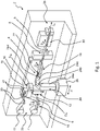
- a packaging machine 2 with a handling device 4 according to the invention is shown in a perspective view.
- the packaging machine 2 is particularly preferably designed as a blister machine, even if the following statements are not limited to this.
- the packaging machine 2 is equipped with a limp, web-shaped packaging material 6, which can be formed here by a form film web, and comprises at least a first processing station 8 for processing the web-shaped packaging material 6 in the packaging machine 2.
- the web-shaped packaging material 6 can be transported in an input area 2a of the Packaging machine 2 may be provided on a supply roll 7, for example.
- the web-shaped packaging material 6 has a longitudinal direction Lv.
- the packaging machine 2 can be equipped with a further web-shaped packaging material 10, which can be formed here by a cover film web.
- the additional packaging material 10 in web form is also provided on a supply roll 11 in the area of the input area 2a of the packaging machine 2 .
- the packaging machine 2 preferably includes a plurality of processing stations, which includes the first processing station 8 and at least one second processing station 12 and which is set up for processing the web-shaped packaging material 6 and in the present case also the additional web-shaped packaging material 10 .
- the plurality of processing stations includes, for example, a cutting and gluing device 14 for connecting successive material webs of the packaging material 6, a heating device 16 for heating the web-shaped packaging material 6, the second processing station 12, which is used here, e.g. as a shaping device for forming wells in the web-shaped packaging material 6, a filling device 18 for filling the wells with medical or pharmaceutical products, the first processing station 8, which is embodied here, for example, as a sealing device for sealing the cover film web to the shaped film web, and a punching device 20 for punching out individual blister packs.
- a cutting and gluing device 14 for connecting successive material webs of the packaging material 6, a heating device 16 for heating the web-shaped packaging material 6, the second processing station 12, which is used here, e.g. as a shaping device for forming wells in the web-shaped packaging material 6, a filling device 18 for filling the wells with medical or pharmaceutical products, the first processing station 8, which is embodied here, for example, as a sealing device for sealing the
- the packaging machine 2 can also comprise a plurality of processing stations, which for example comprise the first processing station 8 and the punching device 20 .
- Each processing station of the plurality of processing stations 8, 12, 14, 16, 18, 20 has a Flow direction, in which the respective packaging material 6, 10 passes through the processing station and each supplemented by the arrow D is characterized by the reference number of the respective processing station. It is understood that the packaging machine can in principle have any number of processing stations and the first and the second processing station 8, 12 are not related to the 1 examples given are limited.
- the packaging material 6 in web form has already been completely inserted into the packaging machine 2 .
- This means that the web-shaped packaging material 6 is guided through all the necessary processing stations 8, 12, 14, 16, 18, 20 and around all the necessary guiding and deflecting elements 21.
- the other web-like packaging material 10 has also already been completely inserted into the packaging machine 2 and guided through the necessary processing stations 8 , 20 and around the necessary guide and deflection elements 23 .
- the handling device 4 for inserting a free end section (see 3 ) of the web-shaped packaging material 6, 10 into the first processing station 8 and, if desired, into further processing stations of the plurality of processing stations 12, 14, 16, 18, 20.
- the handling device 4 comprises a holding device 22 which is set up for detecting the web-shaped packaging material 6, 10 and with reference to FIG Figures 2-4 is described in more detail.
- the packaging machine 2 includes a robot 24 that carries the handling device 4 that is mounted on the robot 24 .
- the robot 24 is suitable for guiding the handling device 4 with the holding device 22 through the packaging machine 2 along a path specified for the web-shaped packaging material 6, 10 and for moving the holding device 22 as required. If the robot 24 is only to cover areas of the packaging machine 2 that are within the reach of its arms 24a-d, the robot 24 can be arranged in a stationary manner. However, the robot 24 can preferably be moved along the packaging machine 2, in particular linearly moved, as indicated by the arrow X in 1 marked. For example, a base 26 that carries the entire robot 24 can be movably mounted for this purpose.
- the range of movement of the robot 24 preferably extends so far along the packaging machine 2 that its range covers the packaging machine 2 between its input area 2a and its output area 2b. It is particularly advantageous if at least the majority of processing stations 8 , 12 , 14 , 16 , 18 , 20 are within reach of the robot 24 .
- the handling device 4 with the holding device 22 is in 2 in a side view and in 3 shown in a perspective view, wherein in 3 a part of the web-shaped packaging material 6 can also be seen. It goes without saying that the statements also apply analogously to a further web-shaped packaging material 10 gripped by the holding device.
- the holding device 22 extends further in a longitudinal direction L H of the holding device 22 than in transverse directions Q 1 , Q 2 of the holding device 22.
- the transverse directions Q 1 , Q 2 of the holding device 22 are aligned perpendicular to the longitudinal direction L H of the holding device 22 and perpendicular to one another.
- the holding device 22 preferably has an essentially rod-shaped or tubular body 28 which correspondingly extends further in the longitudinal direction L H of the holding device 22 than in the transverse directions Q 1 , Q 2 of the holding device 22 .
- a length L HE of the holding device 22 is defined in the longitudinal direction L H of the holding device 22 from the first end 22a to the second end 22b.
- a width B HE of the holding device 22 is defined parallel to the transverse direction Q1 and a height H HE is defined parallel to the transverse direction Q2.
- the maximum dimension of the holding device 22 directed in the corresponding direction is decisive for the width B HE and the height H HE in each case.
- the body 28 of the holding device 22 can extend in the longitudinal direction L H from a housing 30 of the handling device 4, which can accommodate a controller and a media supply, for example.
- the holding device 22 has a first end 22a and a second end 22b opposite the first end 22a in the longitudinal direction LH.
- the first end 22a is preferably firmly connected to the housing 30, while the second end 22b forms a free end of the holding device 22.
- the handling device 4 comprises a coupling 32 for connecting the handling device 4 to a complementary coupling on the robot 24, in particular at a free end of a robot arm 24d.
- the coupling 32 of the handling device 4 and the complementary coupling on the robot 24 preferably form a quick-change system.
- the holding device 22 also has a contact area 34 which is defined by at least one contact point 36 for contacting the web-shaped packaging material 6 .
- the contact area 34 in turn has a curvature in the longitudinal direction L H , which preferably extends over the entire contact area 34 in the longitudinal direction L H of the holding device 22 . That is, the contact area 34 is completely curved.
- the holding device 22 can have a plurality of selective contact points (contact points) for the web-shaped packaging material 6, which define the contact region 34 and, in a cross-sectional view parallel to the longitudinal direction L H of the holding device 22 and perpendicular to the longitudinal direction L V of the packaging material 6, on a plane corresponding to the curvature of the Contact area 34 are curved line. This is in 2 indicated by contact points, one of which is representatively identified by the reference numeral 36a, and the dashed, curved line 34a.
- the holding device 22 can also have a linear contact (contact line) with the web-shaped packaging material 6, which then itself has a corresponding curvature in the previously defined cross-sectional view.
- a linear contact contact line
- planar contact contact surface
- a linear or planar contact can extend continuously along the contact area 34 or, as illustrated, be formed from a plurality of contact points 36 .
- the holding device 22 has a plurality of contact points 36 which can each be linear or flat, here are ring-shaped and are spaced apart from one another in the longitudinal direction L H of the holding device 22 .
- the plurality of contact points 36 lie on the line 34a which is curved in accordance with the curvature of the contact area 34 .
- the curvature of the contact area 34 which is 2 illustrated by dashed line 34a may be defined by a quadratic function or by a segment of a circle be educated.
- a radius of curvature R is corresponding for the curved line 34a in FIG 2 marked.
- the holding device 22 is designed as a suction device. This is particularly suitable for handling sensitive packaging materials, such as foils, can be easily activated and deactivated for detecting or releasing the packaging material and is designed to save space.
- the suction device can comprise a plurality of suction cups 38 which are preferably arranged one behind the other in the longitudinal direction L H of the holding device 22 .
- the suction cups 38 can be independently actuatable individually or in groups, for example by being in fluid communication with a vacuum source, such as a vacuum pump, by means of a separate line.
- the suction cups 38 can also all be connected to a line 40 inside the holding device 22, as in 2 shown schematically.
- a plurality of bores 42 can be provided in the holding device 22, which connect the suction cups 38 via the line 40 to a vacuum source.
- the holding device 22 grasps a free end section 44 of the web-shaped packaging material 6 .
- a width of the web-shaped packaging material is in 3 denoted by the reference B VM .
- the longitudinal direction L H of the holding device 22 is aligned perpendicularly to the longitudinal direction L V of the web-shaped packaging material 6 or parallel to the transverse direction Qv of the web-shaped packaging material 6.
- the curvature of the contact area 34 of the holding device 22 causes the web-shaped packaging material 6 grasped by the holding device 22 to be arched in the transverse direction Qv of the packaging material 6 in accordance with the curvature of the contact area 34 .
- a tensile force generated that in 3 characterized by the arrow F Z and is directed transversely to the longitudinal direction L V along the curvature.
- the tensile force F Z in turn results in a certain stability of the free end section 44 of the web-shaped packaging material 6, which means that the free end section 44 protrudes from the holding device 22 in the longitudinal direction L V and does not hang down in the direction of the weight force.
- the part of the free end section 44 of the web-shaped packaging material 6 that protrudes from the holding device 22 is also referred to as the overhang 48 .
- This excess length 48 can now be introduced into at least one processing station of the plurality of processing stations 8 , 12 , 14 , 16 , 18 , 20 by means of the handling device 4 .
- a distance A is defined between the leading edge 46 of the web-shaped packaging material 6 and the holding device 22 parallel to the longitudinal direction L V of the web-shaped packaging material 6 .
- the distance A indicates the size of the overhang 48 .
- the greater the curvature of the contact area 34 and thus the curvature of the web-shaped packaging material 6 in the free end section 44 or the greater the tensile force F Z the greater the distance A can be selected, since this means greater stability of the free end section 44 and thus of the overhang 48.
- the method according to the invention for inserting the limp, web-like packaging material 6 into the packaging machine 2 is described below with reference to FIG Figures 1 to 6 described.
- the method initially comprises the provision of the web-shaped packaging material 6, preferably on the supply roll 7 in the input area 2a of the packaging machine 2 (see Fig. 1 ).
- the web-shaped packaging material 6 is then gripped by the handling device 4, preferably first on the supply roll 7, with the free end section 44 of the web-shaped packaging material 6 being arched in the transverse direction Qv of the web-shaped packaging material 6 and protruding from the handling device 4, as shown in FIG 3 shown.
- This is achieved in particular in that the free end portion 44 of the web-shaped packaging material 6 is gripped by the holding device 22, the contact area 34 of which has a curvature, as with reference to FIG 2 and 3 described.
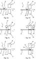
- the gripped free end section 44 of the web-shaped packaging material 6 is then brought to at least the first processing station 8 of the packaging machine 2 by means of the handling device 4, as shown in FIG Figures 4a and 5a shown, and then introduced into the first processing station 8 (see Figures 4b, 5b ).
- the free end portion 44 is inserted into a gap between upper and lower tools 8a, 8b of the first work station 8. It is particularly advantageous that the overhang 48 of the free end section 44 protrudes stably from the holding device 22 and can therefore be easily introduced into the first processing station 8 .
- the handling device 4, especially its holding device 22, and the free end section 44 of the web-shaped packaging material 6 can be guided together through the first processing station 8 and, if necessary, further processing stations of the plurality of processing stations (see Fig. Figure 5b ) after the free end section 44 has been introduced into the respective processing station (see Figure 5a ).
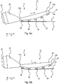
- the gripping of the web-shaped packaging material 6 by means of the handling device 4 includes the rolling of the holding device 22 on a surface 6a of the web-shaped packaging material 6 in the transverse direction Q V of the web-shaped packaging material 6 along the curvature of the contact area 34. This ensures that the web-shaped packaging material 6 is grasped cleanly and without creases and a well-defined tensile force F Z is generated in the web-shaped packaging material 6.
- the contact area 34 of the holding device 22 initially grasps the packaging material 6 in the area of the first end 22a of the holding device 22 (see Fig. Figure 6a ) and increasing during rolling along the curvature of the contact area 34 (see Fig. Figure 6b ), up to the area of the second end 22b of the holding device 22 (see Figure 6c ).
- the holding device 22 is designed as a suction device, as illustrated, this means that one suction cup 38 after the other grips the web-shaped packaging material 6 in the longitudinal direction L H of the holding device 22 .
- a suction cup 38 of the plurality of suction cups 38 grips the web-shaped packaging material 6 that is closest to the first end 22a of the holding device 22.
- a suction cup 38 following in the longitudinal direction LH of the holding device 22 can thus already be arranged in the immediate vicinity of the surface 6a of the web-shaped packaging material.
- the holding device 22 is further unrolled on the surface 6A so that the two next suction cups 38 are in engagement with the web-shaped packaging material 6 in the illustrated state. It can already be seen that the web-shaped packaging material 6 is curved between the suction cups 38 which have already gripped the packaging material 6 .
- the holding device 22 has completely grasped the web-shaped packaging material 6 and this is arched along the curvature of the contact area 34 .
- the Figures 3 and 6c show the same state of the web-shaped packaging material 6 gripped by the holding device 22 in different views.
- the steps described in connection with the holding device 22 can also be transferred analogously to other holding devices which have a curved contact area for grasping the web-shaped packaging material.
- the method steps described herein also apply analogously to the handling of the further packaging material 10 in web form. Since the method is preferably carried out by a handling device 4 according to the invention or a packaging machine 2 that includes such a device, all features described with regard to the handling device 4 and the packaging machine 2 can be transferred analogously to the method and vice versa.
Landscapes
- Engineering & Computer Science (AREA)
- Mechanical Engineering (AREA)
- Robotics (AREA)
- Replacement Of Web Rolls (AREA)
- Containers And Plastic Fillers For Packaging (AREA)
Priority Applications (4)
| Application Number | Priority Date | Filing Date | Title |
|---|---|---|---|
| EP20207738.4A EP4001137B1 (fr) | 2020-11-16 | 2020-11-16 | Procédé de manipulation de matière d'emballage en forme de bande |
| US17/512,274 US11866211B2 (en) | 2020-11-16 | 2021-10-27 | Handling device and method for handling web-shaped packaging material |
| KR1020210149408A KR102643023B1 (ko) | 2020-11-16 | 2021-11-03 | 웹-형상 포장 재료의 포장 방법 및 핸들링 장치 |
| CN202111350421.3A CN114572466B (zh) | 2020-11-16 | 2021-11-15 | 用于处理网状包装材料的处理装置和方法 |
Applications Claiming Priority (1)
| Application Number | Priority Date | Filing Date | Title |
|---|---|---|---|
| EP20207738.4A EP4001137B1 (fr) | 2020-11-16 | 2020-11-16 | Procédé de manipulation de matière d'emballage en forme de bande |
Publications (2)
| Publication Number | Publication Date |
|---|---|
| EP4001137A1 true EP4001137A1 (fr) | 2022-05-25 |
| EP4001137B1 EP4001137B1 (fr) | 2025-03-19 |
Family
ID=73452041
Family Applications (1)
| Application Number | Title | Priority Date | Filing Date |
|---|---|---|---|
| EP20207738.4A Active EP4001137B1 (fr) | 2020-11-16 | 2020-11-16 | Procédé de manipulation de matière d'emballage en forme de bande |
Country Status (4)
| Country | Link |
|---|---|
| US (1) | US11866211B2 (fr) |
| EP (1) | EP4001137B1 (fr) |
| KR (1) | KR102643023B1 (fr) |
| CN (1) | CN114572466B (fr) |
Citations (7)
| Publication number | Priority date | Publication date | Assignee | Title |
|---|---|---|---|---|
| EP0270109A2 (fr) * | 1986-12-04 | 1988-06-08 | Finnah GmbH | Procédé et dispositif pour étirer des bandes de matériau, spécialement des bandes à couvercles pour récipients d'emballage |
| US5156387A (en) * | 1989-10-16 | 1992-10-20 | Fuji Photo Film Co., Ltd. | Suction cup for sheet feed mechanism |
| DE19817174A1 (de) * | 1997-05-07 | 1998-11-12 | Heidelberger Druckmasch Ag | Vorrichtung zum Trennen eines Bogens |
| WO2001074696A2 (fr) * | 2000-04-04 | 2001-10-11 | The Procter & Gamble Company | Dispositif et procede d'alignement d'une bande |
| DE10017347A1 (de) * | 2000-04-07 | 2001-10-18 | Brueckner Maschbau | Kluppe mit progressiver Öffnungs- und Schließcharakteristik |
| EP2735407A2 (fr) * | 2012-11-27 | 2014-05-28 | Kabushiki Kaisha Yaskawa Denki | Système de robot, main d'aspiration et procédé de production de produit comprenant une pièce |
| US10526157B2 (en) * | 2016-11-04 | 2020-01-07 | Cp Packaging, Inc. | Web material advancement arrangement with an entry drive system in a packaging machine |
Family Cites Families (7)
| Publication number | Priority date | Publication date | Assignee | Title |
|---|---|---|---|---|
| JPH06308246A (ja) | 1993-04-23 | 1994-11-04 | Mitsubishi Heavy Ind Ltd | シート供給装置 |
| JP5170548B2 (ja) | 2008-07-25 | 2013-03-27 | 株式会社Ihi | シート材分離機能付き把持ハンドとこれを用いたシート材分離把持方法 |
| US20100323868A1 (en) * | 2009-06-18 | 2010-12-23 | Ishida Co., Ltd. | Bag-making and packaging apparatus |
| JP2015034071A (ja) | 2013-08-08 | 2015-02-19 | 日本電気硝子株式会社 | シート部材搬送装置、シート部材支持装置、シート部材検査装置、およびシート部材搬送方法 |
| JP2015139835A (ja) * | 2014-01-27 | 2015-08-03 | 株式会社安川電機 | ロボットシステム、吸着ハンドおよびワークを含む製品の製造方法 |
| EP3081497B1 (fr) * | 2015-04-14 | 2018-03-14 | Tetra Laval Holdings & Finance SA | Machine d'emballage et procédé de production d'emballages à partir d'un matériau d'emballage |
| DE102016110008A1 (de) * | 2016-04-04 | 2017-10-05 | Sig Technology Ag | Vorrichtung zum einseitigen Verschließen von Packungsmänteln für die Herstellung von Verbundpackungen |
-
2020
- 2020-11-16 EP EP20207738.4A patent/EP4001137B1/fr active Active
-
2021
- 2021-10-27 US US17/512,274 patent/US11866211B2/en active Active
- 2021-11-03 KR KR1020210149408A patent/KR102643023B1/ko active Active
- 2021-11-15 CN CN202111350421.3A patent/CN114572466B/zh active Active
Patent Citations (7)
| Publication number | Priority date | Publication date | Assignee | Title |
|---|---|---|---|---|
| EP0270109A2 (fr) * | 1986-12-04 | 1988-06-08 | Finnah GmbH | Procédé et dispositif pour étirer des bandes de matériau, spécialement des bandes à couvercles pour récipients d'emballage |
| US5156387A (en) * | 1989-10-16 | 1992-10-20 | Fuji Photo Film Co., Ltd. | Suction cup for sheet feed mechanism |
| DE19817174A1 (de) * | 1997-05-07 | 1998-11-12 | Heidelberger Druckmasch Ag | Vorrichtung zum Trennen eines Bogens |
| WO2001074696A2 (fr) * | 2000-04-04 | 2001-10-11 | The Procter & Gamble Company | Dispositif et procede d'alignement d'une bande |
| DE10017347A1 (de) * | 2000-04-07 | 2001-10-18 | Brueckner Maschbau | Kluppe mit progressiver Öffnungs- und Schließcharakteristik |
| EP2735407A2 (fr) * | 2012-11-27 | 2014-05-28 | Kabushiki Kaisha Yaskawa Denki | Système de robot, main d'aspiration et procédé de production de produit comprenant une pièce |
| US10526157B2 (en) * | 2016-11-04 | 2020-01-07 | Cp Packaging, Inc. | Web material advancement arrangement with an entry drive system in a packaging machine |
Also Published As
| Publication number | Publication date |
|---|---|
| CN114572466B (zh) | 2024-04-26 |
| US11866211B2 (en) | 2024-01-09 |
| KR20220066836A (ko) | 2022-05-24 |
| US20220153461A1 (en) | 2022-05-19 |
| EP4001137B1 (fr) | 2025-03-19 |
| CN114572466A (zh) | 2022-06-03 |
| KR102643023B1 (ko) | 2024-03-05 |
Similar Documents
| Publication | Publication Date | Title |
|---|---|---|
| AT406668B (de) | Vorrichtung zur übernahme und beförderung von gegenständen | |
| EP3017940B2 (fr) | Procédé et dispositif de fabrication de sacs à partir de corps de sac tubulaires | |
| EP3414105B1 (fr) | Dispositif et procédé d'usinage d'un substrat | |
| EP2858798B1 (fr) | Dispositif et procédé de décorticage et de séparation de découpes | |
| EP1947045A2 (fr) | Procédé et dispositif destinés à la séparation de couches de film et installation de soudage d'une pièce d'insertion | |
| AT511305A1 (de) | Blechentnahmestation | |
| EP1370463A1 (fr) | Dispositifs et procede pour mettre en paquet une pile d'objets de type feuille | |
| EP4001137B1 (fr) | Procédé de manipulation de matière d'emballage en forme de bande | |
| DE69510600T2 (de) | Vorrichtung zur Einführung von wesentlich rechteckigen Wäschestücken in eine Zuführvorrichtung | |
| EP2253569A2 (fr) | Transfert de piles de papier | |
| DE102008017443B4 (de) | Vorrichtung und Verfahren zur Herstellung von Säcken aus Schlauchstücken | |
| DE102013014732B4 (de) | Verfahren und Vorrichtung zur Herstellung von Kreuzboden-Säcken | |
| EP1914165A1 (fr) | Procédé et dispositif destinés à former une rangée d'objets plats | |
| WO2009121542A1 (fr) | Équipement et procédé de fabrication de sacs à partir de tronçons de tube souple | |
| EP1213245A1 (fr) | Procédé et dispositif de pliage de feuilles | |
| EP3461606B1 (fr) | Machine à poinçonner ou à faire des empreintes et procédé de traitement de feuilles | |
| DE102009048921A1 (de) | Bündelungsvorrichtung | |
| CH675223A5 (en) | Alignment aid for cutting machine for sheets | |
| DE10156664B4 (de) | Vorrichtung zum rotierenden Stanzen von Nutzen aus Einzelbögen | |
| DE102022119207A1 (de) | Verfahren und Vorrichtung zum Verbinden von zwei jeweils von einer Bobine ablaufenden Materialbahnen | |
| EP3967637A1 (fr) | Dispositif et procédé d'épissurage et de fourniture continue d'une bande continue de feuille | |
| EP4263200B1 (fr) | Dispositif de séparation et procédé pour séparer localement une bande de film | |
| DE3151568C2 (de) | Vorrichtung zum Z-förmigen Falten von Schlauch- oder Bahnabschnitten | |
| DE102012007598B4 (de) | Schiebereinheit und Verfahren zum Positionieren von Produkten auf einem Verpackungsträger | |
| AT524968B1 (de) | Vorrichtung und Verfahren zur Herstellung von Säcken aus Schlauchstücken |
Legal Events
| Date | Code | Title | Description |
|---|---|---|---|
| PUAI | Public reference made under article 153(3) epc to a published international application that has entered the european phase |
Free format text: ORIGINAL CODE: 0009012 |
|
| STAA | Information on the status of an ep patent application or granted ep patent |
Free format text: STATUS: THE APPLICATION HAS BEEN PUBLISHED |
|
| AK | Designated contracting states |
Kind code of ref document: A1 Designated state(s): AL AT BE BG CH CY CZ DE DK EE ES FI FR GB GR HR HU IE IS IT LI LT LU LV MC MK MT NL NO PL PT RO RS SE SI SK SM TR |
|
| STAA | Information on the status of an ep patent application or granted ep patent |
Free format text: STATUS: REQUEST FOR EXAMINATION WAS MADE |
|
| 17P | Request for examination filed |
Effective date: 20221114 |
|
| RBV | Designated contracting states (corrected) |
Designated state(s): AL AT BE BG CH CY CZ DE DK EE ES FI FR GB GR HR HU IE IS IT LI LT LU LV MC MK MT NL NO PL PT RO RS SE SI SK SM TR |
|
| STAA | Information on the status of an ep patent application or granted ep patent |
Free format text: STATUS: EXAMINATION IS IN PROGRESS |
|
| 17Q | First examination report despatched |
Effective date: 20240325 |
|
| GRAP | Despatch of communication of intention to grant a patent |
Free format text: ORIGINAL CODE: EPIDOSNIGR1 |
|
| STAA | Information on the status of an ep patent application or granted ep patent |
Free format text: STATUS: GRANT OF PATENT IS INTENDED |
|
| INTG | Intention to grant announced |
Effective date: 20241115 |
|
| GRAS | Grant fee paid |
Free format text: ORIGINAL CODE: EPIDOSNIGR3 |
|
| GRAA | (expected) grant |
Free format text: ORIGINAL CODE: 0009210 |
|
| STAA | Information on the status of an ep patent application or granted ep patent |
Free format text: STATUS: THE PATENT HAS BEEN GRANTED |
|
| P01 | Opt-out of the competence of the unified patent court (upc) registered |
Free format text: CASE NUMBER: APP_5887/2025 Effective date: 20250204 |
|
| AK | Designated contracting states |
Kind code of ref document: B1 Designated state(s): AL AT BE BG CH CY CZ DE DK EE ES FI FR GB GR HR HU IE IS IT LI LT LU LV MC MK MT NL NO PL PT RO RS SE SI SK SM TR |
|
| REG | Reference to a national code |
Ref country code: GB Ref legal event code: FG4D Free format text: NOT ENGLISH |
|
| REG | Reference to a national code |
Ref country code: CH Ref legal event code: EP |
|
| REG | Reference to a national code |
Ref country code: DE Ref legal event code: R096 Ref document number: 502020010629 Country of ref document: DE |
|
| REG | Reference to a national code |
Ref country code: IE Ref legal event code: FG4D Free format text: LANGUAGE OF EP DOCUMENT: GERMAN |
|
| PG25 | Lapsed in a contracting state [announced via postgrant information from national office to epo] |
Ref country code: RS Free format text: LAPSE BECAUSE OF FAILURE TO SUBMIT A TRANSLATION OF THE DESCRIPTION OR TO PAY THE FEE WITHIN THE PRESCRIBED TIME-LIMIT Effective date: 20250619 |
|
| PG25 | Lapsed in a contracting state [announced via postgrant information from national office to epo] |
Ref country code: FI Free format text: LAPSE BECAUSE OF FAILURE TO SUBMIT A TRANSLATION OF THE DESCRIPTION OR TO PAY THE FEE WITHIN THE PRESCRIBED TIME-LIMIT Effective date: 20250319 |
|
| REG | Reference to a national code |
Ref country code: LT Ref legal event code: MG9D |
|
| PG25 | Lapsed in a contracting state [announced via postgrant information from national office to epo] |
Ref country code: NO Free format text: LAPSE BECAUSE OF FAILURE TO SUBMIT A TRANSLATION OF THE DESCRIPTION OR TO PAY THE FEE WITHIN THE PRESCRIBED TIME-LIMIT Effective date: 20250619 |
|
| PG25 | Lapsed in a contracting state [announced via postgrant information from national office to epo] |
Ref country code: HR Free format text: LAPSE BECAUSE OF FAILURE TO SUBMIT A TRANSLATION OF THE DESCRIPTION OR TO PAY THE FEE WITHIN THE PRESCRIBED TIME-LIMIT Effective date: 20250319 |
|
| PG25 | Lapsed in a contracting state [announced via postgrant information from national office to epo] |
Ref country code: LV Free format text: LAPSE BECAUSE OF FAILURE TO SUBMIT A TRANSLATION OF THE DESCRIPTION OR TO PAY THE FEE WITHIN THE PRESCRIBED TIME-LIMIT Effective date: 20250319 |
|
| PG25 | Lapsed in a contracting state [announced via postgrant information from national office to epo] |
Ref country code: BG Free format text: LAPSE BECAUSE OF FAILURE TO SUBMIT A TRANSLATION OF THE DESCRIPTION OR TO PAY THE FEE WITHIN THE PRESCRIBED TIME-LIMIT Effective date: 20250319 Ref country code: GR Free format text: LAPSE BECAUSE OF FAILURE TO SUBMIT A TRANSLATION OF THE DESCRIPTION OR TO PAY THE FEE WITHIN THE PRESCRIBED TIME-LIMIT Effective date: 20250620 |
|
| REG | Reference to a national code |
Ref country code: NL Ref legal event code: MP Effective date: 20250319 |
|
| PG25 | Lapsed in a contracting state [announced via postgrant information from national office to epo] |
Ref country code: NL Free format text: LAPSE BECAUSE OF FAILURE TO SUBMIT A TRANSLATION OF THE DESCRIPTION OR TO PAY THE FEE WITHIN THE PRESCRIBED TIME-LIMIT Effective date: 20250319 |
|
| PG25 | Lapsed in a contracting state [announced via postgrant information from national office to epo] |
Ref country code: SE Free format text: LAPSE BECAUSE OF FAILURE TO SUBMIT A TRANSLATION OF THE DESCRIPTION OR TO PAY THE FEE WITHIN THE PRESCRIBED TIME-LIMIT Effective date: 20250319 |
|
| PG25 | Lapsed in a contracting state [announced via postgrant information from national office to epo] |
Ref country code: SM Free format text: LAPSE BECAUSE OF FAILURE TO SUBMIT A TRANSLATION OF THE DESCRIPTION OR TO PAY THE FEE WITHIN THE PRESCRIBED TIME-LIMIT Effective date: 20250319 |
|
| PG25 | Lapsed in a contracting state [announced via postgrant information from national office to epo] |
Ref country code: ES Free format text: LAPSE BECAUSE OF FAILURE TO SUBMIT A TRANSLATION OF THE DESCRIPTION OR TO PAY THE FEE WITHIN THE PRESCRIBED TIME-LIMIT Effective date: 20250319 Ref country code: PT Free format text: LAPSE BECAUSE OF FAILURE TO SUBMIT A TRANSLATION OF THE DESCRIPTION OR TO PAY THE FEE WITHIN THE PRESCRIBED TIME-LIMIT Effective date: 20250721 |
|
| PG25 | Lapsed in a contracting state [announced via postgrant information from national office to epo] |
Ref country code: PL Free format text: LAPSE BECAUSE OF FAILURE TO SUBMIT A TRANSLATION OF THE DESCRIPTION OR TO PAY THE FEE WITHIN THE PRESCRIBED TIME-LIMIT Effective date: 20250319 |
|
| PG25 | Lapsed in a contracting state [announced via postgrant information from national office to epo] |
Ref country code: EE Free format text: LAPSE BECAUSE OF FAILURE TO SUBMIT A TRANSLATION OF THE DESCRIPTION OR TO PAY THE FEE WITHIN THE PRESCRIBED TIME-LIMIT Effective date: 20250319 Ref country code: CZ Free format text: LAPSE BECAUSE OF FAILURE TO SUBMIT A TRANSLATION OF THE DESCRIPTION OR TO PAY THE FEE WITHIN THE PRESCRIBED TIME-LIMIT Effective date: 20250319 |
|
| PG25 | Lapsed in a contracting state [announced via postgrant information from national office to epo] |
Ref country code: RO Free format text: LAPSE BECAUSE OF FAILURE TO SUBMIT A TRANSLATION OF THE DESCRIPTION OR TO PAY THE FEE WITHIN THE PRESCRIBED TIME-LIMIT Effective date: 20250319 |
|
| PG25 | Lapsed in a contracting state [announced via postgrant information from national office to epo] |
Ref country code: SK Free format text: LAPSE BECAUSE OF FAILURE TO SUBMIT A TRANSLATION OF THE DESCRIPTION OR TO PAY THE FEE WITHIN THE PRESCRIBED TIME-LIMIT Effective date: 20250319 |
|
| PG25 | Lapsed in a contracting state [announced via postgrant information from national office to epo] |
Ref country code: IS Free format text: LAPSE BECAUSE OF FAILURE TO SUBMIT A TRANSLATION OF THE DESCRIPTION OR TO PAY THE FEE WITHIN THE PRESCRIBED TIME-LIMIT Effective date: 20250719 |
|
| REG | Reference to a national code |
Ref country code: DE Ref legal event code: R097 Ref document number: 502020010629 Country of ref document: DE |
|
| PGFP | Annual fee paid to national office [announced via postgrant information from national office to epo] |
Ref country code: DE Payment date: 20251127 Year of fee payment: 6 |
|
| PG25 | Lapsed in a contracting state [announced via postgrant information from national office to epo] |
Ref country code: DK Free format text: LAPSE BECAUSE OF FAILURE TO SUBMIT A TRANSLATION OF THE DESCRIPTION OR TO PAY THE FEE WITHIN THE PRESCRIBED TIME-LIMIT Effective date: 20250319 |
|
| PGFP | Annual fee paid to national office [announced via postgrant information from national office to epo] |
Ref country code: IT Payment date: 20251127 Year of fee payment: 6 |
|
| PLBE | No opposition filed within time limit |
Free format text: ORIGINAL CODE: 0009261 |
|
| STAA | Information on the status of an ep patent application or granted ep patent |
Free format text: STATUS: NO OPPOSITION FILED WITHIN TIME LIMIT |
|
| REG | Reference to a national code |
Ref country code: CH Ref legal event code: L10 Free format text: ST27 STATUS EVENT CODE: U-0-0-L10-L00 (AS PROVIDED BY THE NATIONAL OFFICE) Effective date: 20260128 |
|
| 26N | No opposition filed |
Effective date: 20251222 |