EP4001141A1 - Stopfen für einen behälter - Google Patents
Stopfen für einen behälter Download PDFInfo
- Publication number
- EP4001141A1 EP4001141A1 EP21201975.6A EP21201975A EP4001141A1 EP 4001141 A1 EP4001141 A1 EP 4001141A1 EP 21201975 A EP21201975 A EP 21201975A EP 4001141 A1 EP4001141 A1 EP 4001141A1
- Authority
- EP
- European Patent Office
- Prior art keywords
- olive
- container
- wall
- stopper
- plug according
- Prior art date
- Legal status (The legal status is an assumption and is not a legal conclusion. Google has not performed a legal analysis and makes no representation as to the accuracy of the status listed.)
- Granted
Links
Images



Classifications
-
- B—PERFORMING OPERATIONS; TRANSPORTING
- B65—CONVEYING; PACKING; STORING; HANDLING THIN OR FILAMENTARY MATERIAL
- B65D—CONTAINERS FOR STORAGE OR TRANSPORT OF ARTICLES OR MATERIALS, e.g. BAGS, BARRELS, BOTTLES, BOXES, CANS, CARTONS, CRATES, DRUMS, JARS, TANKS, HOPPERS, FORWARDING CONTAINERS; ACCESSORIES, CLOSURES, OR FITTINGS THEREFOR; PACKAGING ELEMENTS; PACKAGES
- B65D41/00—Caps, e.g. crown caps or crown seals, i.e. members having parts arranged for engagement with the external periphery of a neck or wall defining a pouring opening or discharge aperture; Protective cap-like covers for closure members, e.g. decorative covers of metal foil or paper
- B65D41/32—Caps or cap-like covers with lines of weakness, tearing-strips, tags, or like opening or removal devices, e.g. to facilitate formation of pouring openings
- B65D41/58—Caps or cap-like covers combined with stoppers
-
- B—PERFORMING OPERATIONS; TRANSPORTING
- B65—CONVEYING; PACKING; STORING; HANDLING THIN OR FILAMENTARY MATERIAL
- B65D—CONTAINERS FOR STORAGE OR TRANSPORT OF ARTICLES OR MATERIALS, e.g. BAGS, BARRELS, BOTTLES, BOXES, CANS, CARTONS, CRATES, DRUMS, JARS, TANKS, HOPPERS, FORWARDING CONTAINERS; ACCESSORIES, CLOSURES, OR FITTINGS THEREFOR; PACKAGING ELEMENTS; PACKAGES
- B65D51/00—Closures not otherwise provided for
- B65D51/24—Closures not otherwise provided for combined or co-operating with auxiliary devices for non-closing purposes
- B65D51/28—Closures not otherwise provided for combined or co-operating with auxiliary devices for non-closing purposes with auxiliary containers for additional articles or materials
- B65D51/30—Closures not otherwise provided for combined or co-operating with auxiliary devices for non-closing purposes with auxiliary containers for additional articles or materials for desiccators
-
- B—PERFORMING OPERATIONS; TRANSPORTING
- B65—CONVEYING; PACKING; STORING; HANDLING THIN OR FILAMENTARY MATERIAL
- B65D—CONTAINERS FOR STORAGE OR TRANSPORT OF ARTICLES OR MATERIALS, e.g. BAGS, BARRELS, BOTTLES, BOXES, CANS, CARTONS, CRATES, DRUMS, JARS, TANKS, HOPPERS, FORWARDING CONTAINERS; ACCESSORIES, CLOSURES, OR FITTINGS THEREFOR; PACKAGING ELEMENTS; PACKAGES
- B65D39/00—Closures arranged within necks or pouring openings or in discharge apertures, e.g. stoppers
- B65D39/0005—Closures arranged within necks or pouring openings or in discharge apertures, e.g. stoppers made in one piece
- B65D39/0023—Plastic cap-shaped hollow plugs
-
- B—PERFORMING OPERATIONS; TRANSPORTING
- B65—CONVEYING; PACKING; STORING; HANDLING THIN OR FILAMENTARY MATERIAL
- B65D—CONTAINERS FOR STORAGE OR TRANSPORT OF ARTICLES OR MATERIALS, e.g. BAGS, BARRELS, BOTTLES, BOXES, CANS, CARTONS, CRATES, DRUMS, JARS, TANKS, HOPPERS, FORWARDING CONTAINERS; ACCESSORIES, CLOSURES, OR FITTINGS THEREFOR; PACKAGING ELEMENTS; PACKAGES
- B65D41/00—Caps, e.g. crown caps or crown seals, i.e. members having parts arranged for engagement with the external periphery of a neck or wall defining a pouring opening or discharge aperture; Protective cap-like covers for closure members, e.g. decorative covers of metal foil or paper
- B65D41/32—Caps or cap-like covers with lines of weakness, tearing-strips, tags, or like opening or removal devices, e.g. to facilitate formation of pouring openings
- B65D41/46—Snap-on caps or cap-like covers
- B65D41/48—Snap-on caps or cap-like covers non-metallic, e.g. made of paper or plastics
- B65D41/485—Snap-on caps or cap-like covers non-metallic, e.g. made of paper or plastics with integral internal sealing means
-
- B—PERFORMING OPERATIONS; TRANSPORTING
- B65—CONVEYING; PACKING; STORING; HANDLING THIN OR FILAMENTARY MATERIAL
- B65D—CONTAINERS FOR STORAGE OR TRANSPORT OF ARTICLES OR MATERIALS, e.g. BAGS, BARRELS, BOTTLES, BOXES, CANS, CARTONS, CRATES, DRUMS, JARS, TANKS, HOPPERS, FORWARDING CONTAINERS; ACCESSORIES, CLOSURES, OR FITTINGS THEREFOR; PACKAGING ELEMENTS; PACKAGES
- B65D45/00—Clamping or other pressure-applying devices for securing or retaining closure members
-
- B—PERFORMING OPERATIONS; TRANSPORTING
- B65—CONVEYING; PACKING; STORING; HANDLING THIN OR FILAMENTARY MATERIAL
- B65D—CONTAINERS FOR STORAGE OR TRANSPORT OF ARTICLES OR MATERIALS, e.g. BAGS, BARRELS, BOTTLES, BOXES, CANS, CARTONS, CRATES, DRUMS, JARS, TANKS, HOPPERS, FORWARDING CONTAINERS; ACCESSORIES, CLOSURES, OR FITTINGS THEREFOR; PACKAGING ELEMENTS; PACKAGES
- B65D50/00—Closures with means for discouraging unauthorised opening or removal thereof, with or without indicating means, e.g. child-proof closures
-
- B—PERFORMING OPERATIONS; TRANSPORTING
- B65—CONVEYING; PACKING; STORING; HANDLING THIN OR FILAMENTARY MATERIAL
- B65D—CONTAINERS FOR STORAGE OR TRANSPORT OF ARTICLES OR MATERIALS, e.g. BAGS, BARRELS, BOTTLES, BOXES, CANS, CARTONS, CRATES, DRUMS, JARS, TANKS, HOPPERS, FORWARDING CONTAINERS; ACCESSORIES, CLOSURES, OR FITTINGS THEREFOR; PACKAGING ELEMENTS; PACKAGES
- B65D51/00—Closures not otherwise provided for
- B65D51/24—Closures not otherwise provided for combined or co-operating with auxiliary devices for non-closing purposes
- B65D51/26—Closures not otherwise provided for combined or co-operating with auxiliary devices for non-closing purposes with means for keeping contents in position, e.g. resilient means
-
- B—PERFORMING OPERATIONS; TRANSPORTING
- B65—CONVEYING; PACKING; STORING; HANDLING THIN OR FILAMENTARY MATERIAL
- B65D—CONTAINERS FOR STORAGE OR TRANSPORT OF ARTICLES OR MATERIALS, e.g. BAGS, BARRELS, BOTTLES, BOXES, CANS, CARTONS, CRATES, DRUMS, JARS, TANKS, HOPPERS, FORWARDING CONTAINERS; ACCESSORIES, CLOSURES, OR FITTINGS THEREFOR; PACKAGING ELEMENTS; PACKAGES
- B65D55/00—Accessories for container closures not otherwise provided for
-
- B—PERFORMING OPERATIONS; TRANSPORTING
- B65—CONVEYING; PACKING; STORING; HANDLING THIN OR FILAMENTARY MATERIAL
- B65D—CONTAINERS FOR STORAGE OR TRANSPORT OF ARTICLES OR MATERIALS, e.g. BAGS, BARRELS, BOTTLES, BOXES, CANS, CARTONS, CRATES, DRUMS, JARS, TANKS, HOPPERS, FORWARDING CONTAINERS; ACCESSORIES, CLOSURES, OR FITTINGS THEREFOR; PACKAGING ELEMENTS; PACKAGES
- B65D55/00—Accessories for container closures not otherwise provided for
- B65D55/02—Locking devices; Means for discouraging or indicating unauthorised opening or removal of closure
Definitions
- the invention relates to a stopper for a container, with a lid with a peripheral wall surrounding the neck of the container, on the lower edge of which a circumferential tear-off safety ring is formed to protect the container contents from tampering with inward-pointing blocking lugs, which in the fastening position of the stopper have an outward-pointing Reach under the annular projection of the container, and with an olive provided with an external annular bead for clamping engagement in the container opening.
- stoppers are known and have proved their worth many times over in order to seal the contents of the container tightly with the help of the olive, with the tamper-evident ring ensuring that the contents of the container cannot be tampered with without authorization.
- a user wants to remove the stopper from the container for the first time, he or she first tears the tamper-evident ring off the lower edge of the peripheral wall surrounding the container, after which he can pry the stopper off the container neck.
- the stopper Since the stopper is a mass-produced item, its production costs should be as low as possible, with the amount of plastic material used being an important cost factor.
- the present invention is based on the object of specifying a stopper for a container which reliably seals the contents of the container and which can be removed more easily than is the case with the conventional stoppers, even when the olive is firmly seated in the container.
- the stopper should be manufacturable with less plastic material.
- the invention provides that in the circular cover of the stopper a circular, concentric indentation channel is formed, which has a radially outer annular wall and a radially inner annular wall which are connected to each other by a bottom wall.
- the outer annular wall and the radially inner annular wall are preferably parallel to each other and perpendicular to the central circular cap portion and the outer annular cap portion to which they are molded.
- the deepening channel thus preferably has a U-shape in cross section.
- the invention further provides that the radially outer annular wall forms the olive, which has the peripheral annular bead on its outside, which causes the clamping engagement in the neck of the container.
- the ring-shaped olive is connected at its lower end to the bottom wall of the indentation channel, which supports the olive against the action of the lateral forces when it is clamped into the container neck, the olive can be made shorter compared to conventional plugs, thereby reducing the amount of for The plastic material used in the stopper can be reduced. In addition, the wall thickness of the olive supported in this way can also be reduced.
- the indented channel also makes it easier to pry the stopper off the container neck, in that the indented channel can be compressed a little when the stopper is pushed back from the container neck, which makes it easier to remove the stopper from the container neck.
- the invention also provides that recesses which reach through the locking ring and extend beyond the blocking lugs on both sides are formed directly above the blocking lugs. These recesses are created by lateral slides of the injection molding tool, which together with an inner contour sleeve form the blocking lugs, as is the case with a conventional plug with a closed lid in FIG DE 42 36 741 C1 is described. These lateral cutouts ensure that no foreign matter can get close to the container opening from the outside, as would be the case if the blocking attachments were formed by plungers that would be guided through cutouts in the cover part. These recesses in the outer ring-shaped cover area would otherwise make it more difficult to pry off the plug, since the outer ring-shaped cover area would not have the required rigidity.
- the plug expediently contains a spiral hold-down device, the elastic spiral webs of which, which end in a closing ring, can be formed on the deepening channel.
- the indentation groove is formed on the central circular cap portion and the outer annular cap portion, and the lower end portion of the radially outer annular wall forming the olive may be tapered in a straight line to facilitate demoulding of the stopper during manufacture.
- this slope also serves as an attachment aid when the closure on the tube is automatically plugged. This also makes it easier to pry off the plug.
- the upper side of the ring-shaped cover area be provided with at least one circumferential rib projecting upwards.
- the olive ring has a corrugated wall surface on its inside, which is formed by a large number of grooves in the wall of the olive running in the axial direction of the stopper.
- the grooves can have a constant depth of about 10% to about 50% of the minimum wall thickness of the olive ring, with the appropriate value depending on the plastic material used and the geometry of the corrugation.
- the webs of the corrugation preferably have a curved cross-sectional shape.
- peripheral wall of the plug and the retaining ring are connected to each other at points lying between the blocking lugs with short webs which can be easily torn off.
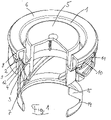
- FIG. 1 shows an embodiment of the stopper according to the invention, in the circular cover of which is formed a concentric deepening channel 1 containing a radially outer annular wall 2, a bottom wall 3 and an inner annular wall 4.
- the depression channel 1 has a U-shape in cross section and is formed on a central circular cover portion 5 and an outer annular cover portion 6 .
- the radially inner annular wall 4 is extended beyond the bottom wall 3 and together with the annular wall 4 forms the peripheral wall 7 of a desiccant chamber.
- a circumferential wall 8 angled at right angles is connected to the annular lid area 6 , on the lower edge of which a tear-off securing ring 9 is formed to protect the contents of the container from being tampered with.
- the radially outer annular wall 2 of the deepening channel 1 is designed as an olive in that it is provided with an annular bead 12 running around the outside for clamping engagement in the opening of a container (not shown).
- the lower end portion 13 of the olive runs in a straight line obliquely inwards.
- a spiral hold-down device 14 is formed with its elastic spiral webs 15 on the bottom wall 3 of the deepening channel 1 .
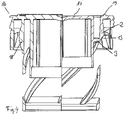
- FIG. 12 shows an identical stopper with the exception that radially extending ribs 7, 8 are formed on the top of the central cap portion 5 and on the top of the annular cap portion 6, which increase the rigidity of the two cap portions.
- the protruding webs 7 and 8 are each uniformly spaced apart over the entire circumference of the cover area 5, 6 is formed.
- figure 3 shows a compilation of a conventional plug 16 in the left half of the figure and the plug 17 according to the invention in the right half of the figure. From this comparison it can be seen that in the stopper 17 according to the invention the olive 2 is considerably shorter than the olive 18 of the conventional stopper 16, which is possible because the olive 2 is held and supported by the bottom wall 3. As a result of this support, the olive 2 develops the same pressing force as the longer olive 18, which also makes it considerably easier to lever off a container because of the shorter dimensions.
- the inclined surface 13 at the lower end of the olive 2 also contributes to this.
- a corrugation can be formed on the radially inner surface of the olive 2 .
- This corrugation which consists of closely spaced grooves and in between projections with a rounded cross-section, makes it easier to lever off the stopper according to the invention, while at the same time the contact pressure of the olive required for the tightness of the container contents is maintained.
Landscapes
- Engineering & Computer Science (AREA)
- Mechanical Engineering (AREA)
- Closures For Containers (AREA)
Abstract
Description
- Die Erfindung betrifft einen Stopfen für einen Behälter, mit einem Deckel mit einer den Hals des Behälters umgreifenden Umfangswand, an deren Unterkante ein umlaufender abreißbarer Sicherungsring zur Originalitätssicherung des Behälterinhalts mit nach innen weisenden Blockieransätzen angeformt ist, die in der Befestigungslage des Stopfens einen nach außen weisenden Ringvorsprung des Behälters untergreifen, und mit einer mit einer außen umlaufenden Ringwulst versehenen Olive zum klemmenden Eingriff in die Behälteröffnung.
- Derartige Stopfen sind bekannt und haben sich vielfach bewährt, um mit Hilfe der Olive den Behälterinhalt dicht zu verschließen, wobei der Originalitätssicherungsring gewährleistet, dass der Behälterinhalt nicht unbefugt manipuliert werden kann. Wenn ein Benutzer erstmalig den Stopfen von dem Behälter abnehmen will, reißt er zuvor den Originalitätssicherungsring von der Unterkante der dem Behälter umgreifenden Umfangswand ab, woraufhin er den Stopfen von dem Behälterhals abhebeln kann.
- Bei den unvermeidlichen Herstellungstoleranzen kann es passieren, dass die ringförmige Olive in einem so festen Klemmsitz in dem Behälterhals steckt, dass eine beträchtliche Kraft erforderlich ist, um die an dem Deckel angeformte Umfangswand und die Olive von dem Behälterhals zu trennen, was z.B. für betagte Benutzer problematisch sein kann. Dabei ist das schräge "Abhebeln" des Stopfens auch durch den unnachgiebigen Deckel des Stopfens erschwert.
- Da es sich bei dem Stopfen um einen Massenartikel handelt, sollen dessen Herstellungskosten möglichst niedrig sein, wobei die Menge des eingesetzten Kunststoffmaterials ein wichtiger Kostenfaktor ist.
- Der vorliegenden Erfindung liegt die Aufgabe zugrunde, einen Stopfen für einen Behälter anzugeben, der den Behälterinhalt sicher abdichtet und auch bei einem festen Klemmsitz der Olive in dem Behälter leichter abgenommen werden kann, als dies bei den bisher üblichen Stopfen der Fall ist. Außerdem soll der Stopfen mit weniger Kunststoffmaterial herstellbar sein.
- Diese Aufgabe wird erfindungsgemäß durch die Merkmale des Patentanspruchs 1 gelöst.
- Vorteilhafte Ausgestaltungen der Erfindung sind in den Unteransprüchen gekennzeichnet.
- Die Erfindung sieht vor, dass in dem kreisrunden Deckel des Stopfens eine kreisförmige, konzentrische Vertiefungsrinne ausgebildet ist, die eine radial äußere Ringwand und eine radial innere Ringwand hat, die durch eine Bodenwand miteinander verbunden sind. Die äußere Ringwand und die radial innere Ringwand verlaufen bevorzugt parallel zueinander und im rechten Winkel zu dem mittigen kreisförmigen Deckelbereich und dem äußeren ringförmigen Deckelbereich, an denen sie angeformt sind. Die Vertiefungsrinne hat damit bevorzugt querschnittlich eine U-Form.
- Weiter sieht die Erfindung vor, dass die radial äußere Ringwand die Olive bildet, die an ihrer Außenseite die umlaufende Ringwulst hat, die den klemmenden Eingriff in den Hals des Behälters hervorruft.
- Da die ringförmige Olive an ihrem unteren Ende mit der Bodenwand der Vertiefungsrinne verbunden ist, die die Olive gegen die Einwirkung der seitlichen Kräfte beim klemmenden Eingriff in den Behälterhals abstützt, kann die Olive im Vergleich zu herkömmlichen Stopfen kürzer ausgeführt werden, wodurch die Menge des für den Stopfen verwendeten Kunststoffmaterials verringert werden kann. Außerdem kann auch die Wandstärke der so abgestützten Olive verringert werden.
- Die Vertiefungsrinne erleichtert zudem das Abhebeln des Stopfens von dem Behälterhals, indem die Vertiefungsrinne beim Zurückschieben des Stopfens vom Behälterhals ein wenig zusammengedrückt werden kann, wodurch das Abnehmen des Stopfens vom Behälterhals erleichtert ist.
- Die Erfindung sieht zudem vor, dass direkt über den Blockieransätzen den Sicherungsring durchgreifende Aussparungen ausgebildet sind, die sich beidseitig über die Blockieransätze hinaus erstrecken. Diese Aussparungen entstehen durch seitliche Schieber des Spritzgussformwerkzeugs, die zusammen mit einer inneren Konturhülse die Blockieransätze ausbilden, wie dies bei einem herkömmlichen Stopfen mit geschlossenem Deckel in der
DE 42 36 741 C1 beschrieben ist. Durch diese seitlichen Aussparungen ist sichergestellt, dass keine Fremdstoffe von außen in die Nähe der Behälteröffnung gelangen können, wie dies bei der Ausbildung der Blockieransätze durch Tauchkerne der Fall wäre, die durch Aussparungen des Deckelteils geführt würden. Durch diese Aussparungen in dem äußeren ringförmigen Deckelbereich würde anderenfalls das Abhebeln des Stopfens erschwert, da der äußere ringförmige Deckelbereich nicht die erforderliche Steifigkeit besitzen würde. - Mit großem Vorteil wird außerdem vorgeschlagen, dass die radial innere Ringwand über die Bodenwand hinaus verlängert ist und die Umfangswand einer Trockenmittelkammer bildet. Außerdem enthält der Stopfen zweckmäßigerweise einen Spiralniederhalter, dessen elastische Spiralstege, die in einem Abschlussring enden, an der Vertiefungsrinne angeformt sein können.
- Die Vertiefungsrinne ist an dem mittigen kreisförmigen Deckelbereich und dem äußeren ringförmigen Deckelbereich angeformt, wobei der untere Endbereich der die Olive bildenden radial äußeren Ringwand geradlinig abgeschrägt sein kann, um bei der Herstellung des Stopfens dessen Entformung zu erleichtern. Gleichzeitig dient diese Schräge auch als Anschlupfhilfe beim automatischen Verstopfen des Verschlusses auf der Röhre. Außerdem wird hierdurch das Abhebeln des Stopfens erleichtert.
- Um die Steifigkeit des Stopfens zu erhöhen, wird mit Vorteil vorgeschlagen, dass die Oberseite des ringförmigen Deckelbereichs mit wenigstens einer nach oben abstehenden umlaufenden Rippen versehen ist.
- Mit großem Vorteil wird außerdem vorgeschlagen, dass der Olivring an seiner Innenseite eine geriffelte Wandfläche hat, die durch eine Vielzahl von in axialer Richtung des Stopfens verlaufenden Nuten in der Wand der Olive gebildet ist. Die Nuten können dabei eine gleichbleibende Tiefe von etwa 10% bis etwa 50% der minimalen Wandstärke des Olivrings haben, wobei der geeignete Wert von dem verwendeten Kunststoffmaterial und der Geometrie der Riffelung abhängt. Die Stege der Riffelung haben vorzugsweise eine gewölbte Querschnittsform.
- Versuche mit einer derart geriffelten Olive haben gezeigt, dass der von der Olive erzeugte Anpressdruck und damit die erreichte Dichtigkeit des Behälterinhalts nur unwesentlich verringert ist, während die Riffelung das Abhebeln des Stopfens vom Behälterhals signifikant erleichtert. Hierdurch können auch Benutzer mit geringer Kraft in den Händen den Stopfen besser handhaben.
- Die Umfangswand des Stopfens und der Sicherungsring sind an zwischen den Blockieransätzen liegenden Stellen mit kurzen Stegen miteinander verbunden, die leicht abgerissen werden können.
- Weitere Einzelheiten der Erfindung ergeben sich aus der nachfolgenden Beschreibung sowie anhand der Zeichnungen. Dabei zeigen:
- Figur 1
- eine perspektivische Darstellung einer teilweise geschnittenen Ausführungsform der Erfindung;
- Figur 2
- eine durch Stege verstärkte Ausführungsform;
- Figur 3
- eine Gegenüberstellung eines herkömmlichen und eines erfindungsgemäßen Stopfens;
- Figur 4
- dieselbe Gegenüberstellung ohne Maße;
- Figur 5
- eine perspektivische Darstellung des erfindungsgemäßen Stopfens der
Figuren 3 und4 . -
Figur 1 zeigt eine Ausführungsform des erfindungsgemäßen Stopfens, in dessen kreisförmigem Deckel eine konzentrische Vertiefungsrinne 1 ausgebildet ist, die eine radial äußere Ringwand 2, eine Bodenwand 3 und eine innere Ringwand 4 enthält. Die Vertiefungsrinne 1 hat querschnittlich eine U-Form und ist an einem mittigen kreisförmigen Deckelbereich 5 und einem äußeren ringförmigen Deckelbereich 6 angeformt. Die radial innere Ringwand 4 ist über die Bodenwand 3 hinaus verlängert und bildet zusammenmit der Ringwand 4 die Umfangswand 7 einer Trockenmittelkammer. - Mit dem ringförmigen Deckelbereich 6 ist eine rechtwinklig abgewinkelte Umfangswand 8 verbunden, an deren Unterkante ein abreißbarer Sicherungsring 9 zur Originalitätssicherung des Behälterinhalts angeformt ist, der mit nach innen weisenden Blockieransätzen 10 verbunden ist. Über den Blockieransätzen 10 befinden sich den Sicherungsring 9 durchgreifende Aussparungen 11.
- Die radial äußere Ringwand 2 der Vertiefungsrinne 1 ist als Olive ausgebildet, indem sie mit einer außen umlaufenden Ringwulst 12 zum klemmenden Eingriff in die Öffnung eines nicht dargestellten Behälters versehen ist. Der untere Endbereich 13 der Olive verläuft geradlinig schräg nach innen.
- Ein Spiralniederhalter 14 ist mit seinen elastischen spiralförmigen Stegen 15 an der Bodenwand 3 der Vertiefungsrinne 1 angeformt.
-
Figur 2 zeigt einen identischen Stopfen mit der Ausnahme, dass auf der Oberseite des mittigen Deckelbereichs 5 und auf der Oberseite des ringförmigen Deckelbereichs 6 in radialer Richtung verlaufende Stege 7, 8 ausgebildet sind, die die Steifigkeit der beiden Deckelbereich erhöhen. Die vorstehenden Stege 7 und 8 sind jeweils gleichmäßig voneinander beabstandet über den gesamten Umfang der Deckelbereich 5, 6 verteilt ausgebildet. -
Figur 3 zeigt eine Zusammenstellung eines herkömmlichen Stopfens 16 in der linken Hälfte der Figur und des erfindungsgemäßen Stopfens 17 in der rechten Figurenhälfte. Aus dieser Gegenüberstellung ist zu sehen, dass bei dem erfindungsgemäßen Stopfen 17 die Olive 2 erheblich kürzer ist als die Olive 18 des herkömmlichen Stopfens 16, was dadurch möglich ist, dass die Olive 2 durch die Bodenwand 3 gehalten und abgestützt ist. Durch diese Abstützung entwickelt die Olive 2 dieselbe Anpresskraft wie die längere Olive 18, wodurch zudem das Abhebeln von einem Behälter wegen der kürzeren Abmessung erheblich erleichtert ist. Hierzu trägt auch die schräge Fläche 13 am unteren Ende der Olive 2 bei. Auf der Oberseite des ringförmigen Deckelbereichs 6 ist eine ringförmig umlaufende Rippe 19 ausgebildet. - Eine Riffelung kann an der radial inneren Fläche der Olive 2 ausgebildet sein. Diese Riffelung, die aus dicht beieinander liegenden Nuten und dazwischen querschnittlich gerundeten Vorsprüngen besteht, erleichtert das Abhebeln des erfindungsgemäßen Stopfens, wobei gleichzeitig der zur Dichtigkeit des Behälterinhalts erforderliche Anpressdruck der Olive erhalten bleibt.
Claims (7)
- Stopfen für einen Behälter, mit einem Deckel mit einer den Hals des Behälters umgreifenden Umfangswand (8), an deren Unterkante ein umlaufender abreißbarer Sicherungsring (9) zur Originalitätssicherung des Behälterinhalts mit nach innen weisenden Blockieransätzen (10) angeformt ist, die in der Befestigungsanlage des Stopfens einen nach außen weisenden Ringvorsprung des Behälters untergreifen, undmit einer mit einer außen umlaufenden Ringwulst (12) versehenen Olive (2) zum klemmenden Eingriff in die Behälteröffnung,dadurch gekennzeichnet,dass in dem Deckel eine kreisförmige konzentrische Vertiefungsrinne (1) ausgebildet ist, die eine radial äußere Ringwand (3) und eine radial innere Ringwand (4) hat, die durch eine Bodenwand (4) miteinander verbunden sind,dass die Vertiefungsrinne (1) an dem mittigen kreisförmigen Deckelbereich (5) und dem äußeren ringförmigen Deckelbereich (6) angeformt ist,dass die radial äußere Ringwand die Olive (2) bildet, undund dass die Oberseite des ringförmigen Deckelbereichs (6) mit wenigstens einer nach oben abstehenden Rippe (19) versehen ist.
- Stopfen nach Anspruch 1,dadurch gekennzeichnet,dass die radial innere Ringwand (4) über die Bodenwand (3) hinaus verlängert ist und die Umfangswand einer Trockenmittelkammer (7) bildet.
- Stopfen nach Anspruch 1 oder 2,dadurch gekennzeichnet,dass der untere Endbereich (13) der Olive (2) geradlinig abgeschrägt ist.
- Stopfen nach einem der Ansprüche 1 bis 3,dadurch gekennzeichnet,dass die Olive an ihrer Innenseite eine geriffelte Wandfläche aufweist, die durch eine Vielzahl von in Längsrichtung der Olive verlaufenden Nuten in der Wand der Olive gebildet ist.
- Stopfen nach Anspruch 4,dadurch gekennzeichnet,dass die Nuten eine vorzugsweise gleichbleibende Tiefe von 10% bis 50% der minimalen Wandstärke der Olive haben.
- Stopfen nach einem der Ansprüche 4 oder 5,dadurch gekennzeichnet,dass die Stege zwischen den Nuten eine gewölbte Querschnittsform haben.
- Stopfen nach einem der Ansprüche 1 bis 6,dadurch gekennzeichnet,dass ein Spiralniederhalter (14) an der Bodenwand (3) der Vertiefungsrinne (1) angeformt ist.
Applications Claiming Priority (1)
| Application Number | Priority Date | Filing Date | Title |
|---|---|---|---|
| DE102020129998.2A DE102020129998B3 (de) | 2020-11-13 | 2020-11-13 | Stopfen für einen Behälter |
Publications (2)
| Publication Number | Publication Date |
|---|---|
| EP4001141A1 true EP4001141A1 (de) | 2022-05-25 |
| EP4001141B1 EP4001141B1 (de) | 2024-02-07 |
Family
ID=78087203
Family Applications (1)
| Application Number | Title | Priority Date | Filing Date |
|---|---|---|---|
| EP21201975.6A Active EP4001141B1 (de) | 2020-11-13 | 2021-10-11 | Stopfen für einen behälter |
Country Status (9)
| Country | Link |
|---|---|
| US (1) | US20220153484A1 (de) |
| EP (1) | EP4001141B1 (de) |
| CN (1) | CN114476354A (de) |
| BR (1) | BR102021022630A2 (de) |
| CA (1) | CA3138279C (de) |
| DE (1) | DE102020129998B3 (de) |
| ES (1) | ES2975162T3 (de) |
| MA (1) | MA58540B1 (de) |
| MX (1) | MX2021013952A (de) |
Citations (9)
| Publication number | Priority date | Publication date | Assignee | Title |
|---|---|---|---|---|
| FR1373668A (fr) * | 1963-03-06 | 1964-10-02 | Rical Soc | Bouchon inviolable |
| CH409667A (de) * | 1961-10-25 | 1966-03-15 | Pasinvest Ets | Flaschenverschluss |
| GB1498447A (en) * | 1976-08-04 | 1978-01-18 | Johnsen Jorgensen Plastics Ltd | Container and closure assemblies |
| US4723675A (en) * | 1985-08-22 | 1988-02-09 | Tuwa-Plastik Dr. Herbert Warnecke Kunststoffverarbeitung | Container and cap with guarantee ring |
| DE4236741C1 (de) | 1992-10-30 | 1994-01-13 | Gaplast Gmbh | Stopfen für einen Behälter und Verfahren zur Herstellung des Stopfens |
| EP0798228A1 (de) * | 1996-03-28 | 1997-10-01 | Sarnatech Ammann S.A. | Stopfen für einen Behälter |
| WO2005014415A1 (de) * | 2003-08-07 | 2005-02-17 | Pez International Ag | Verschluss für einen behälter |
| EP2444334A1 (de) * | 2010-09-28 | 2012-04-25 | CEDC International sp. z.o.o. | Sicherheitsflaschendeckel |
| WO2015166994A1 (ja) * | 2014-04-30 | 2015-11-05 | 株式会社吉野工業所 | キャップ |
Family Cites Families (57)
| Publication number | Priority date | Publication date | Assignee | Title |
|---|---|---|---|---|
| US1357831A (en) * | 1920-06-11 | 1920-11-02 | Ewald G Baum | Bottle-cap |
| US1615157A (en) * | 1923-02-05 | 1927-01-18 | Seal Kap Company | Milk-bottle cap |
| US2279263A (en) * | 1939-08-04 | 1942-04-07 | American Seal Kap Corp | Bottle cap |
| US2286865A (en) * | 1939-08-05 | 1942-06-16 | American Scal Kap Corp Of Dela | Die for forming bottle caps |
| US2286070A (en) * | 1940-08-01 | 1942-06-09 | American Seal Kap Corp | Bottle cap |
| US3116846A (en) * | 1959-12-10 | 1964-01-07 | Pasinvest Ets | Bottle closure |
| US3216148A (en) * | 1963-09-17 | 1965-11-09 | Lily Tulip Cup Corp | Receptacle and closure lid therefor |
| US3441161A (en) * | 1967-03-09 | 1969-04-29 | Paul S Van Baarn | Bottle cap |
| US3422978A (en) * | 1967-07-07 | 1969-01-21 | Whitney Blake Co | Self-locking bottle cap |
| BE753828A (fr) * | 1969-10-21 | 1971-01-25 | Segmuller A G | Couvercle de bouteille lavable |
| US3878961A (en) * | 1973-12-28 | 1975-04-22 | Illinois Tool Works | Child resistant closures |
| US4034886A (en) * | 1975-03-28 | 1977-07-12 | United States Steel Corporation | Plastic lids and pails |
| US4098422A (en) * | 1976-04-20 | 1978-07-04 | Slomski Lawrence J | Plastic bottle stopper |
| US4298132A (en) * | 1980-03-24 | 1981-11-03 | United States Steel Corporation | Child-proof lid and pail arrangement |
| US4453647A (en) * | 1983-01-26 | 1984-06-12 | Neat Benjamin C | Plastic container having threaded closure |
| DE3346928A1 (de) * | 1983-12-24 | 1985-07-04 | Friedrich Sanner GmbH & Co KG Spritzgußwerk, 6140 Bensheim | Originalitaetsgesicherte verschlussanordnung |
| EP0202506B1 (de) * | 1985-05-24 | 1992-04-29 | Friedrich Sanner GmbH & Co. KG Spritzgusswerk | Behälterverschluss |
| DE8531702U1 (de) * | 1985-11-09 | 1986-01-09 | Friedrich Sanner GmbH & Co KG Spritzgußwerk, 6140 Bensheim | Trockenstoff-Verschluß |
| DE3622773A1 (de) * | 1986-07-07 | 1988-01-21 | Sanner Friedr Gmbh Co Kg | Kunststoff-verschlussstopfen mit trocknungseinlage |
| US4731512A (en) * | 1987-03-09 | 1988-03-15 | Owens-Illinois Closure Inc. | Child resistant closure with easy open feature for the manually handicapped |
| DE3715938A1 (de) * | 1987-05-13 | 1988-11-24 | Boehringer Mannheim Gmbh | Behaelter fuer teststreifen |
| DE4013799A1 (de) * | 1990-04-28 | 1991-10-31 | Gaplast Gmbh | Behaelter und behaelterverschluss aus kunststoff, insbesondere fuer arznei- und genussmittel |
| US5147052A (en) * | 1991-09-30 | 1992-09-15 | Sunbeam Plastics Corporation | Child resistant closure |
| US5207345A (en) * | 1992-07-10 | 1993-05-04 | Stewart Gene L | Lid adapter for bucket |
| USD364808S (en) * | 1994-04-14 | 1995-12-05 | Beeson And Sons Limited | Closure for a container |
| USD362623S (en) * | 1994-07-13 | 1995-09-26 | Inter-Continental Nail Products | Fingernail glue bottle cap |
| EP0763477B1 (de) * | 1995-08-31 | 1998-12-09 | Friedrich Sanner GmbH & Co. KG Spritzgusswerk | Behälter-Verschluss mit Trockenstoffkammer |
| DE19633495A1 (de) | 1996-08-20 | 1998-02-26 | Sanner Friedr Gmbh Co Kg | Trockenstoff-Verschluß für Behälter |
| US5944214A (en) * | 1997-06-24 | 1999-08-31 | Plastican, Inc. | Reusable lid and container |
| JP4005208B2 (ja) * | 1998-03-10 | 2007-11-07 | 日本クラウンコルク株式会社 | 合成樹脂製キャップ |
| US6398051B1 (en) * | 2000-07-19 | 2002-06-04 | Owens-Illinois Closure Inc. | Tablet package including a tablet hold-down device |
| BR0210605A (pt) * | 2001-07-09 | 2004-09-28 | Crown Cork & Seal Tech Corp | Recipiente e uma tampa de fechamento para o mesmo |
| USD525523S1 (en) * | 2001-11-26 | 2006-07-25 | Beeson And Sons Limited | Cap |
| US7028858B2 (en) * | 2002-02-19 | 2006-04-18 | Stull Technologies, | Quick-twist pop-off closure |
| US7413083B2 (en) * | 2002-04-11 | 2008-08-19 | Csp Technologies, Inc. | Desiccant vial assembly for effervescent tablets |
| CN2618873Y (zh) * | 2003-05-14 | 2004-06-02 | 刘杨 | 复合瓶盖 |
| FR2858301B1 (fr) * | 2003-07-29 | 2006-05-26 | Airsec | Conteneur dessicatif etanche pour le conditionnement de produits sensibles a l'humidite ambiante |
| CN100361877C (zh) * | 2004-12-04 | 2008-01-16 | Sar控股国际有限公司 | 一种用于容器的盖子 |
| EP1787917B1 (de) * | 2005-11-18 | 2009-04-08 | Airsec S.A.S. | Behälter und Kapsel mit Transponder |
| ZA200805222B (en) * | 2005-12-06 | 2009-10-28 | Brasilata Embalagens Metalicas | Can closure arrangement |
| FR2909977B1 (fr) * | 2006-12-13 | 2009-02-27 | Airsec Soc Par Actions Simplif | Bouchon-couvercle deshydratant, refermable, a charniere, a temoin d'effraction et a dispositif de compensation |
| FR2913005B1 (fr) * | 2007-02-23 | 2009-05-15 | Airsec Soc Par Actions Simplif | Ensemble de stockage et de distribution d'objets unitaire muni d'un temoin de premiere ouverture |
| EP2067718A1 (de) * | 2007-12-07 | 2009-06-10 | Vifor (International) Ag | Tablettendispenser |
| US7988004B1 (en) * | 2008-03-19 | 2011-08-02 | Rexam Closures And Containers Inc. | Dispensing closure with tamper evident device |
| UA41091U (uk) * | 2008-04-17 | 2009-05-12 | Гуала Клоужес Патентс Б.В | Закупорювальний засіб |
| WO2009138128A1 (en) * | 2008-05-15 | 2009-11-19 | Airsec S.A.S. | Closure cap for a container |
| US20110147334A1 (en) * | 2009-02-16 | 2011-06-23 | Sumanth Kumar Reddy Mettu | Child resistant closure with improved assembly |
| FR2950865B1 (fr) * | 2009-10-01 | 2011-10-28 | Raymond A & Cie | Coiffe de verrouillage pour recipient a col avec une capsule a pattes de fixation |
| US8534476B2 (en) * | 2009-12-11 | 2013-09-17 | Rexam Healthcare Packaging Inc. | Child-resistant closure shell, closure, and package |
| US8474634B1 (en) * | 2010-04-30 | 2013-07-02 | Rexam Healthcare Packaging Inc. | Child resistant closure with vents |
| US8231020B2 (en) * | 2010-05-27 | 2012-07-31 | Silgan White Cap LLC | Impact resistant closure |
| US9573734B2 (en) * | 2010-06-08 | 2017-02-21 | Clariant Production (France) S.A.S. | Stopper for closing a dispensing opening of a container |
| USD675526S1 (en) * | 2010-12-22 | 2013-02-05 | Sulzer Mixpac Ag | Screw cap |
| CN202687015U (zh) * | 2012-07-21 | 2013-01-23 | 桓台县圣隆桶制品有限公司 | 金属桶盖及带金属桶盖的包装桶 |
| USD704052S1 (en) * | 2013-02-12 | 2014-05-06 | Kao Corporation | Packaging container cap |
| US9957092B2 (en) * | 2014-05-02 | 2018-05-01 | Preddis, Llc | Combination cap and work support system |
| US10137447B1 (en) * | 2017-05-17 | 2018-11-27 | Biotix, Inc. | Ergonomic fluid handling tubes |
-
2020
- 2020-11-13 DE DE102020129998.2A patent/DE102020129998B3/de active Active
-
2021
- 2021-10-11 EP EP21201975.6A patent/EP4001141B1/de active Active
- 2021-10-11 MA MA58540A patent/MA58540B1/fr unknown
- 2021-10-11 ES ES21201975T patent/ES2975162T3/es active Active
- 2021-11-09 US US17/522,032 patent/US20220153484A1/en not_active Abandoned
- 2021-11-09 CA CA3138279A patent/CA3138279C/en active Active
- 2021-11-10 CN CN202111327786.4A patent/CN114476354A/zh active Pending
- 2021-11-10 BR BR102021022630-7A patent/BR102021022630A2/pt unknown
- 2021-11-12 MX MX2021013952A patent/MX2021013952A/es unknown
Patent Citations (9)
| Publication number | Priority date | Publication date | Assignee | Title |
|---|---|---|---|---|
| CH409667A (de) * | 1961-10-25 | 1966-03-15 | Pasinvest Ets | Flaschenverschluss |
| FR1373668A (fr) * | 1963-03-06 | 1964-10-02 | Rical Soc | Bouchon inviolable |
| GB1498447A (en) * | 1976-08-04 | 1978-01-18 | Johnsen Jorgensen Plastics Ltd | Container and closure assemblies |
| US4723675A (en) * | 1985-08-22 | 1988-02-09 | Tuwa-Plastik Dr. Herbert Warnecke Kunststoffverarbeitung | Container and cap with guarantee ring |
| DE4236741C1 (de) | 1992-10-30 | 1994-01-13 | Gaplast Gmbh | Stopfen für einen Behälter und Verfahren zur Herstellung des Stopfens |
| EP0798228A1 (de) * | 1996-03-28 | 1997-10-01 | Sarnatech Ammann S.A. | Stopfen für einen Behälter |
| WO2005014415A1 (de) * | 2003-08-07 | 2005-02-17 | Pez International Ag | Verschluss für einen behälter |
| EP2444334A1 (de) * | 2010-09-28 | 2012-04-25 | CEDC International sp. z.o.o. | Sicherheitsflaschendeckel |
| WO2015166994A1 (ja) * | 2014-04-30 | 2015-11-05 | 株式会社吉野工業所 | キャップ |
Also Published As
| Publication number | Publication date |
|---|---|
| CA3138279C (en) | 2025-10-14 |
| MA58540B1 (fr) | 2024-04-30 |
| CN114476354A (zh) | 2022-05-13 |
| DE102020129998B3 (de) | 2021-10-28 |
| CA3138279A1 (en) | 2022-05-13 |
| ES2975162T3 (es) | 2024-07-03 |
| EP4001141B1 (de) | 2024-02-07 |
| MX2021013952A (es) | 2022-05-16 |
| US20220153484A1 (en) | 2022-05-19 |
| BR102021022630A2 (pt) | 2022-05-24 |
Similar Documents
| Publication | Publication Date | Title |
|---|---|---|
| EP0696994B1 (de) | Verschlusskappe zum verschliessen einer flasche | |
| DE3100629C2 (de) | Gegen unbefugtes Öffnen gesicherter Kunststoffverschluß | |
| DE69917973T2 (de) | Kunstoffverschluss | |
| CH657589A5 (de) | Schraubdeckel mit innen- und aussendeckel. | |
| DE2736833A1 (de) | Sicherheitsverschluss und behaelter- anordnung, insbesondere kindersicherer behaelterverschluss | |
| DE2251563B2 (de) | Verschlußeinrichtung für ein Behälterende mit einem Verschlußdeckel | |
| DE1804549A1 (de) | Sicherheitsverschluss fuer Behaelter | |
| DE10297200T5 (de) | Einlagenloser Abdichtungs-Verschluss für Öffnungen | |
| DE10007367A1 (de) | Verschlusskappe für Infusions- und Transfusionsflaschen | |
| DE19580996B4 (de) | Deckelfaß | |
| DE68917938T2 (de) | Deckel ohne innenbekleidung für kohlensäurehaltige getränkebehälter. | |
| WO2008095478A2 (de) | Behälter mit deckel und verfahren zu seiner herstellung | |
| CH430479A (de) | Aus elastischem Werkstoff bestehender Verschluss für Gefässe mit einer Hinterschneidung an der Mündung | |
| EP3279115B1 (de) | Verfahren zur herstellung eines behälterverschluss-systems | |
| DE202011003216U1 (de) | Tubenverpackung | |
| EP3976496B1 (de) | Verschlussvorrichtung für einen behälter | |
| DE2042951A1 (de) | Kindersichere Sicherheitspackung | |
| EP0026284B1 (de) | Sicherheitsschraubverschluss | |
| EP4001141B1 (de) | Stopfen für einen behälter | |
| DE1924874A1 (de) | Behaelterverschluss | |
| DE202015008143U1 (de) | Spundstopfenverschluss | |
| EP0595212B1 (de) | Stopfen für einen Behälter und Verfahren zur Herstellung des Stopfens | |
| DE2334730A1 (de) | Verschluss fuer behaelter | |
| EP4688594A1 (de) | Ressourcenschonende verschlusseinrichtung | |
| DE1432127A1 (de) | Innenkappenverschluss aus Kunststoff fuer Behaelter |
Legal Events
| Date | Code | Title | Description |
|---|---|---|---|
| PUAI | Public reference made under article 153(3) epc to a published international application that has entered the european phase |
Free format text: ORIGINAL CODE: 0009012 |
|
| STAA | Information on the status of an ep patent application or granted ep patent |
Free format text: STATUS: THE APPLICATION HAS BEEN PUBLISHED |
|
| AK | Designated contracting states |
Kind code of ref document: A1 Designated state(s): AL AT BE BG CH CY CZ DE DK EE ES FI FR GB GR HR HU IE IS IT LI LT LU LV MC MK MT NL NO PL PT RO RS SE SI SK SM TR |
|
| STAA | Information on the status of an ep patent application or granted ep patent |
Free format text: STATUS: REQUEST FOR EXAMINATION WAS MADE |
|
| 17P | Request for examination filed |
Effective date: 20221109 |
|
| RAV | Requested validation state of the european patent: fee paid |
Extension state: TN Effective date: 20221109 Extension state: MA Effective date: 20221109 |
|
| RBV | Designated contracting states (corrected) |
Designated state(s): AL AT BE BG CH CY CZ DE DK EE ES FI FR GB GR HR HU IE IS IT LI LT LU LV MC MK MT NL NO PL PT RO RS SE SI SK SM TR |
|
| RIC1 | Information provided on ipc code assigned before grant |
Ipc: B65D 51/30 20060101ALI20230831BHEP Ipc: B65D 51/26 20060101ALI20230831BHEP Ipc: B65D 41/48 20060101ALI20230831BHEP Ipc: B65D 1/30 20060101AFI20230831BHEP |
|
| GRAP | Despatch of communication of intention to grant a patent |
Free format text: ORIGINAL CODE: EPIDOSNIGR1 |
|
| STAA | Information on the status of an ep patent application or granted ep patent |
Free format text: STATUS: GRANT OF PATENT IS INTENDED |
|
| INTG | Intention to grant announced |
Effective date: 20231020 |
|
| P01 | Opt-out of the competence of the unified patent court (upc) registered |
Effective date: 20231030 |
|
| GRAS | Grant fee paid |
Free format text: ORIGINAL CODE: EPIDOSNIGR3 |
|
| GRAA | (expected) grant |
Free format text: ORIGINAL CODE: 0009210 |
|
| STAA | Information on the status of an ep patent application or granted ep patent |
Free format text: STATUS: THE PATENT HAS BEEN GRANTED |
|
| AK | Designated contracting states |
Kind code of ref document: B1 Designated state(s): AL AT BE BG CH CY CZ DE DK EE ES FI FR GB GR HR HU IE IS IT LI LT LU LV MC MK MT NL NO PL PT RO RS SE SI SK SM TR |
|
| REG | Reference to a national code |
Ref country code: GB Ref legal event code: FG4D Free format text: NOT ENGLISH Ref country code: TN Ref legal event code: VAGR Ref document number: TN/P/2024/000125 Country of ref document: TN |
|
| REG | Reference to a national code |
Ref country code: CH Ref legal event code: EP |
|
| REG | Reference to a national code |
Ref country code: DE Ref legal event code: R096 Ref document number: 502021002631 Country of ref document: DE |
|
| REG | Reference to a national code |
Ref country code: IE Ref legal event code: FG4D Free format text: LANGUAGE OF EP DOCUMENT: GERMAN |
|
| REG | Reference to a national code |
Ref country code: MA Ref legal event code: VAGR Ref document number: 58540 Country of ref document: MA Kind code of ref document: B1 |
|
| REG | Reference to a national code |
Ref country code: LT Ref legal event code: MG9D |
|
| REG | Reference to a national code |
Ref country code: NL Ref legal event code: MP Effective date: 20240207 |
|
| PG25 | Lapsed in a contracting state [announced via postgrant information from national office to epo] |
Ref country code: IS Free format text: LAPSE BECAUSE OF FAILURE TO SUBMIT A TRANSLATION OF THE DESCRIPTION OR TO PAY THE FEE WITHIN THE PRESCRIBED TIME-LIMIT Effective date: 20240607 |
|
| REG | Reference to a national code |
Ref country code: ES Ref legal event code: FG2A Ref document number: 2975162 Country of ref document: ES Kind code of ref document: T3 Effective date: 20240703 |
|
| PG25 | Lapsed in a contracting state [announced via postgrant information from national office to epo] |
Ref country code: LT Free format text: LAPSE BECAUSE OF FAILURE TO SUBMIT A TRANSLATION OF THE DESCRIPTION OR TO PAY THE FEE WITHIN THE PRESCRIBED TIME-LIMIT Effective date: 20240207 |
|
| PG25 | Lapsed in a contracting state [announced via postgrant information from national office to epo] |
Ref country code: GR Free format text: LAPSE BECAUSE OF FAILURE TO SUBMIT A TRANSLATION OF THE DESCRIPTION OR TO PAY THE FEE WITHIN THE PRESCRIBED TIME-LIMIT Effective date: 20240508 |
|
| PG25 | Lapsed in a contracting state [announced via postgrant information from national office to epo] |
Ref country code: NL Free format text: LAPSE BECAUSE OF FAILURE TO SUBMIT A TRANSLATION OF THE DESCRIPTION OR TO PAY THE FEE WITHIN THE PRESCRIBED TIME-LIMIT Effective date: 20240207 Ref country code: HR Free format text: LAPSE BECAUSE OF FAILURE TO SUBMIT A TRANSLATION OF THE DESCRIPTION OR TO PAY THE FEE WITHIN THE PRESCRIBED TIME-LIMIT Effective date: 20240207 Ref country code: RS Free format text: LAPSE BECAUSE OF FAILURE TO SUBMIT A TRANSLATION OF THE DESCRIPTION OR TO PAY THE FEE WITHIN THE PRESCRIBED TIME-LIMIT Effective date: 20240507 |
|
| PG25 | Lapsed in a contracting state [announced via postgrant information from national office to epo] |
Ref country code: RS Free format text: LAPSE BECAUSE OF FAILURE TO SUBMIT A TRANSLATION OF THE DESCRIPTION OR TO PAY THE FEE WITHIN THE PRESCRIBED TIME-LIMIT Effective date: 20240507 Ref country code: NO Free format text: LAPSE BECAUSE OF FAILURE TO SUBMIT A TRANSLATION OF THE DESCRIPTION OR TO PAY THE FEE WITHIN THE PRESCRIBED TIME-LIMIT Effective date: 20240507 Ref country code: NL Free format text: LAPSE BECAUSE OF FAILURE TO SUBMIT A TRANSLATION OF THE DESCRIPTION OR TO PAY THE FEE WITHIN THE PRESCRIBED TIME-LIMIT Effective date: 20240207 Ref country code: LT Free format text: LAPSE BECAUSE OF FAILURE TO SUBMIT A TRANSLATION OF THE DESCRIPTION OR TO PAY THE FEE WITHIN THE PRESCRIBED TIME-LIMIT Effective date: 20240207 Ref country code: IS Free format text: LAPSE BECAUSE OF FAILURE TO SUBMIT A TRANSLATION OF THE DESCRIPTION OR TO PAY THE FEE WITHIN THE PRESCRIBED TIME-LIMIT Effective date: 20240607 Ref country code: HR Free format text: LAPSE BECAUSE OF FAILURE TO SUBMIT A TRANSLATION OF THE DESCRIPTION OR TO PAY THE FEE WITHIN THE PRESCRIBED TIME-LIMIT Effective date: 20240207 Ref country code: GR Free format text: LAPSE BECAUSE OF FAILURE TO SUBMIT A TRANSLATION OF THE DESCRIPTION OR TO PAY THE FEE WITHIN THE PRESCRIBED TIME-LIMIT Effective date: 20240508 Ref country code: FI Free format text: LAPSE BECAUSE OF FAILURE TO SUBMIT A TRANSLATION OF THE DESCRIPTION OR TO PAY THE FEE WITHIN THE PRESCRIBED TIME-LIMIT Effective date: 20240207 Ref country code: BG Free format text: LAPSE BECAUSE OF FAILURE TO SUBMIT A TRANSLATION OF THE DESCRIPTION OR TO PAY THE FEE WITHIN THE PRESCRIBED TIME-LIMIT Effective date: 20240207 |
|
| PG25 | Lapsed in a contracting state [announced via postgrant information from national office to epo] |
Ref country code: PT Free format text: LAPSE BECAUSE OF FAILURE TO SUBMIT A TRANSLATION OF THE DESCRIPTION OR TO PAY THE FEE WITHIN THE PRESCRIBED TIME-LIMIT Effective date: 20240607 Ref country code: PL Free format text: LAPSE BECAUSE OF FAILURE TO SUBMIT A TRANSLATION OF THE DESCRIPTION OR TO PAY THE FEE WITHIN THE PRESCRIBED TIME-LIMIT Effective date: 20240207 |
|
| PG25 | Lapsed in a contracting state [announced via postgrant information from national office to epo] |
Ref country code: SE Free format text: LAPSE BECAUSE OF FAILURE TO SUBMIT A TRANSLATION OF THE DESCRIPTION OR TO PAY THE FEE WITHIN THE PRESCRIBED TIME-LIMIT Effective date: 20240207 Ref country code: PT Free format text: LAPSE BECAUSE OF FAILURE TO SUBMIT A TRANSLATION OF THE DESCRIPTION OR TO PAY THE FEE WITHIN THE PRESCRIBED TIME-LIMIT Effective date: 20240607 Ref country code: PL Free format text: LAPSE BECAUSE OF FAILURE TO SUBMIT A TRANSLATION OF THE DESCRIPTION OR TO PAY THE FEE WITHIN THE PRESCRIBED TIME-LIMIT Effective date: 20240207 Ref country code: LV Free format text: LAPSE BECAUSE OF FAILURE TO SUBMIT A TRANSLATION OF THE DESCRIPTION OR TO PAY THE FEE WITHIN THE PRESCRIBED TIME-LIMIT Effective date: 20240207 |
|
| PG25 | Lapsed in a contracting state [announced via postgrant information from national office to epo] |
Ref country code: DK Free format text: LAPSE BECAUSE OF FAILURE TO SUBMIT A TRANSLATION OF THE DESCRIPTION OR TO PAY THE FEE WITHIN THE PRESCRIBED TIME-LIMIT Effective date: 20240207 |
|
| PG25 | Lapsed in a contracting state [announced via postgrant information from national office to epo] |
Ref country code: SM Free format text: LAPSE BECAUSE OF FAILURE TO SUBMIT A TRANSLATION OF THE DESCRIPTION OR TO PAY THE FEE WITHIN THE PRESCRIBED TIME-LIMIT Effective date: 20240207 |
|
| PG25 | Lapsed in a contracting state [announced via postgrant information from national office to epo] |
Ref country code: CZ Free format text: LAPSE BECAUSE OF FAILURE TO SUBMIT A TRANSLATION OF THE DESCRIPTION OR TO PAY THE FEE WITHIN THE PRESCRIBED TIME-LIMIT Effective date: 20240207 Ref country code: EE Free format text: LAPSE BECAUSE OF FAILURE TO SUBMIT A TRANSLATION OF THE DESCRIPTION OR TO PAY THE FEE WITHIN THE PRESCRIBED TIME-LIMIT Effective date: 20240207 |
|
| PG25 | Lapsed in a contracting state [announced via postgrant information from national office to epo] |
Ref country code: SK Free format text: LAPSE BECAUSE OF FAILURE TO SUBMIT A TRANSLATION OF THE DESCRIPTION OR TO PAY THE FEE WITHIN THE PRESCRIBED TIME-LIMIT Effective date: 20240207 |
|
| PG25 | Lapsed in a contracting state [announced via postgrant information from national office to epo] |
Ref country code: SM Free format text: LAPSE BECAUSE OF FAILURE TO SUBMIT A TRANSLATION OF THE DESCRIPTION OR TO PAY THE FEE WITHIN THE PRESCRIBED TIME-LIMIT Effective date: 20240207 Ref country code: SK Free format text: LAPSE BECAUSE OF FAILURE TO SUBMIT A TRANSLATION OF THE DESCRIPTION OR TO PAY THE FEE WITHIN THE PRESCRIBED TIME-LIMIT Effective date: 20240207 Ref country code: RO Free format text: LAPSE BECAUSE OF FAILURE TO SUBMIT A TRANSLATION OF THE DESCRIPTION OR TO PAY THE FEE WITHIN THE PRESCRIBED TIME-LIMIT Effective date: 20240207 Ref country code: EE Free format text: LAPSE BECAUSE OF FAILURE TO SUBMIT A TRANSLATION OF THE DESCRIPTION OR TO PAY THE FEE WITHIN THE PRESCRIBED TIME-LIMIT Effective date: 20240207 Ref country code: DK Free format text: LAPSE BECAUSE OF FAILURE TO SUBMIT A TRANSLATION OF THE DESCRIPTION OR TO PAY THE FEE WITHIN THE PRESCRIBED TIME-LIMIT Effective date: 20240207 Ref country code: CZ Free format text: LAPSE BECAUSE OF FAILURE TO SUBMIT A TRANSLATION OF THE DESCRIPTION OR TO PAY THE FEE WITHIN THE PRESCRIBED TIME-LIMIT Effective date: 20240207 |
|
| REG | Reference to a national code |
Ref country code: DE Ref legal event code: R097 Ref document number: 502021002631 Country of ref document: DE |
|
| PLBE | No opposition filed within time limit |
Free format text: ORIGINAL CODE: 0009261 |
|
| STAA | Information on the status of an ep patent application or granted ep patent |
Free format text: STATUS: NO OPPOSITION FILED WITHIN TIME LIMIT |
|
| 26N | No opposition filed |
Effective date: 20241108 |
|
| PG25 | Lapsed in a contracting state [announced via postgrant information from national office to epo] |
Ref country code: SI Free format text: LAPSE BECAUSE OF FAILURE TO SUBMIT A TRANSLATION OF THE DESCRIPTION OR TO PAY THE FEE WITHIN THE PRESCRIBED TIME-LIMIT Effective date: 20240207 |
|
| PG25 | Lapsed in a contracting state [announced via postgrant information from national office to epo] |
Ref country code: MC Free format text: LAPSE BECAUSE OF FAILURE TO SUBMIT A TRANSLATION OF THE DESCRIPTION OR TO PAY THE FEE WITHIN THE PRESCRIBED TIME-LIMIT Effective date: 20240207 |
|
| PG25 | Lapsed in a contracting state [announced via postgrant information from national office to epo] |
Ref country code: LU Free format text: LAPSE BECAUSE OF NON-PAYMENT OF DUE FEES Effective date: 20241011 Ref country code: BE Free format text: LAPSE BECAUSE OF NON-PAYMENT OF DUE FEES Effective date: 20241031 |
|
| REG | Reference to a national code |
Ref country code: BE Ref legal event code: MM Effective date: 20241031 |
|
| PG25 | Lapsed in a contracting state [announced via postgrant information from national office to epo] |
Ref country code: IE Free format text: LAPSE BECAUSE OF NON-PAYMENT OF DUE FEES Effective date: 20241011 |
|
| REG | Reference to a national code |
Ref country code: CH Ref legal event code: U11 Free format text: ST27 STATUS EVENT CODE: U-0-0-U10-U11 (AS PROVIDED BY THE NATIONAL OFFICE) Effective date: 20251101 |
|
| VSFP | Annual fee paid to validation state [announced via postgrant information from national office to epo] |
Ref country code: MA Payment date: 20241108 Year of fee payment: 4 Ref country code: MA Payment date: 20251008 Year of fee payment: 5 |
|
| PGFP | Annual fee paid to national office [announced via postgrant information from national office to epo] |
Ref country code: DE Payment date: 20251212 Year of fee payment: 5 |
|
| PGFP | Annual fee paid to national office [announced via postgrant information from national office to epo] |
Ref country code: GB Payment date: 20251022 Year of fee payment: 5 |
|
| PGFP | Annual fee paid to national office [announced via postgrant information from national office to epo] |
Ref country code: AT Payment date: 20260113 Year of fee payment: 5 |
|
| PGFP | Annual fee paid to national office [announced via postgrant information from national office to epo] |
Ref country code: IT Payment date: 20251024 Year of fee payment: 5 |
|
| PGFP | Annual fee paid to national office [announced via postgrant information from national office to epo] |
Ref country code: FR Payment date: 20251030 Year of fee payment: 5 |
|
| PGFP | Annual fee paid to national office [announced via postgrant information from national office to epo] |
Ref country code: TR Payment date: 20251006 Year of fee payment: 5 |
|
| PGFP | Annual fee paid to national office [announced via postgrant information from national office to epo] |
Ref country code: CH Payment date: 20251101 Year of fee payment: 5 |
|
| PG25 | Lapsed in a contracting state [announced via postgrant information from national office to epo] |
Ref country code: CY Free format text: LAPSE BECAUSE OF FAILURE TO SUBMIT A TRANSLATION OF THE DESCRIPTION OR TO PAY THE FEE WITHIN THE PRESCRIBED TIME-LIMIT; INVALID AB INITIO Effective date: 20211011 |
|
| PGFP | Annual fee paid to national office [announced via postgrant information from national office to epo] |
Ref country code: ES Payment date: 20251216 Year of fee payment: 5 |
|
| PG25 | Lapsed in a contracting state [announced via postgrant information from national office to epo] |
Ref country code: HU Free format text: LAPSE BECAUSE OF FAILURE TO SUBMIT A TRANSLATION OF THE DESCRIPTION OR TO PAY THE FEE WITHIN THE PRESCRIBED TIME-LIMIT; INVALID AB INITIO Effective date: 20211011 |