EP4001187A1 - Procédé de positionnement transversal d'un article à transporter - Google Patents
Procédé de positionnement transversal d'un article à transporter Download PDFInfo
- Publication number
- EP4001187A1 EP4001187A1 EP21206389.5A EP21206389A EP4001187A1 EP 4001187 A1 EP4001187 A1 EP 4001187A1 EP 21206389 A EP21206389 A EP 21206389A EP 4001187 A1 EP4001187 A1 EP 4001187A1
- Authority
- EP
- European Patent Office
- Prior art keywords
- conveyor
- unit
- another
- units
- article
- Prior art date
- Legal status (The legal status is an assumption and is not a legal conclusion. Google has not performed a legal analysis and makes no representation as to the accuracy of the status listed.)
- Pending
Links
Images


Classifications
-
- B—PERFORMING OPERATIONS; TRANSPORTING
- B65—CONVEYING; PACKING; STORING; HANDLING THIN OR FILAMENTARY MATERIAL
- B65G—TRANSPORT OR STORAGE DEVICES, e.g. CONVEYORS FOR LOADING OR TIPPING, SHOP CONVEYOR SYSTEMS OR PNEUMATIC TUBE CONVEYORS
- B65G47/00—Article or material-handling devices associated with conveyors; Methods employing such devices
- B65G47/02—Devices for feeding articles or materials to conveyors
- B65G47/04—Devices for feeding articles or materials to conveyors for feeding articles
- B65G47/06—Devices for feeding articles or materials to conveyors for feeding articles from a single group of articles arranged in orderly pattern, e.g. workpieces in magazines
- B65G47/08—Devices for feeding articles or materials to conveyors for feeding articles from a single group of articles arranged in orderly pattern, e.g. workpieces in magazines spacing or grouping the articles during feeding
- B65G47/084—Devices for feeding articles or materials to conveyors for feeding articles from a single group of articles arranged in orderly pattern, e.g. workpieces in magazines spacing or grouping the articles during feeding grouping articles in a predetermined 2-dimensional pattern
-
- B—PERFORMING OPERATIONS; TRANSPORTING
- B65—CONVEYING; PACKING; STORING; HANDLING THIN OR FILAMENTARY MATERIAL
- B65G—TRANSPORT OR STORAGE DEVICES, e.g. CONVEYORS FOR LOADING OR TIPPING, SHOP CONVEYOR SYSTEMS OR PNEUMATIC TUBE CONVEYORS
- B65G57/00—Stacking of articles
- B65G57/32—Stacking of articles characterised by stacking during transit
-
- B—PERFORMING OPERATIONS; TRANSPORTING
- B26—HAND CUTTING TOOLS; CUTTING; SEVERING
- B26D—CUTTING; DETAILS COMMON TO MACHINES FOR PERFORATING, PUNCHING, CUTTING-OUT, STAMPING-OUT OR SEVERING
- B26D3/00—Cutting work characterised by the nature of the cut made; Apparatus therefor
- B26D3/24—Cutting work characterised by the nature of the cut made; Apparatus therefor to obtain segments other than slices, e.g. cutting pies
-
- B—PERFORMING OPERATIONS; TRANSPORTING
- B26—HAND CUTTING TOOLS; CUTTING; SEVERING
- B26D—CUTTING; DETAILS COMMON TO MACHINES FOR PERFORATING, PUNCHING, CUTTING-OUT, STAMPING-OUT OR SEVERING
- B26D7/00—Details of apparatus for cutting, cutting-out, stamping-out, punching, perforating, or severing by means other than cutting
- B26D7/27—Means for performing other operations combined with cutting
- B26D7/32—Means for performing other operations combined with cutting for conveying or stacking cut product
-
- B—PERFORMING OPERATIONS; TRANSPORTING
- B65—CONVEYING; PACKING; STORING; HANDLING THIN OR FILAMENTARY MATERIAL
- B65G—TRANSPORT OR STORAGE DEVICES, e.g. CONVEYORS FOR LOADING OR TIPPING, SHOP CONVEYOR SYSTEMS OR PNEUMATIC TUBE CONVEYORS
- B65G15/00—Conveyors having endless load-conveying surfaces, i.e. belts and like continuous members, to which tractive effort is transmitted by means other than endless driving elements of similar configuration
- B65G15/30—Belts or like endless load-carriers
- B65G15/50—Endless load-carriers consisting of a series of parallel ropes or belt strips
-
- B—PERFORMING OPERATIONS; TRANSPORTING
- B65—CONVEYING; PACKING; STORING; HANDLING THIN OR FILAMENTARY MATERIAL
- B65G—TRANSPORT OR STORAGE DEVICES, e.g. CONVEYORS FOR LOADING OR TIPPING, SHOP CONVEYOR SYSTEMS OR PNEUMATIC TUBE CONVEYORS
- B65G41/00—Supporting frames or bases for conveyors as a whole, e.g. transportable conveyor frames
- B65G41/001—Supporting frames or bases for conveyors as a whole, e.g. transportable conveyor frames with the conveyor adjustably mounted on the supporting frame or base
-
- B—PERFORMING OPERATIONS; TRANSPORTING
- B65—CONVEYING; PACKING; STORING; HANDLING THIN OR FILAMENTARY MATERIAL
- B65G—TRANSPORT OR STORAGE DEVICES, e.g. CONVEYORS FOR LOADING OR TIPPING, SHOP CONVEYOR SYSTEMS OR PNEUMATIC TUBE CONVEYORS
- B65G47/00—Article or material-handling devices associated with conveyors; Methods employing such devices
- B65G47/22—Devices influencing the relative position or the attitude of articles during transit by conveyors
- B65G47/26—Devices influencing the relative position or the attitude of articles during transit by conveyors arranging the articles, e.g. varying spacing between individual articles
-
- B—PERFORMING OPERATIONS; TRANSPORTING
- B65—CONVEYING; PACKING; STORING; HANDLING THIN OR FILAMENTARY MATERIAL
- B65G—TRANSPORT OR STORAGE DEVICES, e.g. CONVEYORS FOR LOADING OR TIPPING, SHOP CONVEYOR SYSTEMS OR PNEUMATIC TUBE CONVEYORS
- B65G47/00—Article or material-handling devices associated with conveyors; Methods employing such devices
- B65G47/52—Devices for transferring articles or materials between conveyors i.e. discharging or feeding devices
- B65G47/56—Devices for transferring articles or materials between conveyors i.e. discharging or feeding devices to or from inclined or vertical conveyor sections
- B65G47/57—Devices for transferring articles or materials between conveyors i.e. discharging or feeding devices to or from inclined or vertical conveyor sections for articles
-
- B—PERFORMING OPERATIONS; TRANSPORTING
- B65—CONVEYING; PACKING; STORING; HANDLING THIN OR FILAMENTARY MATERIAL
- B65G—TRANSPORT OR STORAGE DEVICES, e.g. CONVEYORS FOR LOADING OR TIPPING, SHOP CONVEYOR SYSTEMS OR PNEUMATIC TUBE CONVEYORS
- B65G47/00—Article or material-handling devices associated with conveyors; Methods employing such devices
- B65G47/52—Devices for transferring articles or materials between conveyors i.e. discharging or feeding devices
- B65G47/68—Devices for transferring articles or materials between conveyors i.e. discharging or feeding devices adapted to receive articles arriving in one layer from one conveyor lane and to transfer them in individual layers to more than one conveyor lane or to one broader conveyor lane, or vice versa, e.g. combining the flows of articles conveyed by more than one conveyor
- B65G47/681—Devices for transferring articles or materials between conveyors i.e. discharging or feeding devices adapted to receive articles arriving in one layer from one conveyor lane and to transfer them in individual layers to more than one conveyor lane or to one broader conveyor lane, or vice versa, e.g. combining the flows of articles conveyed by more than one conveyor from distinct, separate conveyor lanes
-
- B—PERFORMING OPERATIONS; TRANSPORTING
- B26—HAND CUTTING TOOLS; CUTTING; SEVERING
- B26D—CUTTING; DETAILS COMMON TO MACHINES FOR PERFORATING, PUNCHING, CUTTING-OUT, STAMPING-OUT OR SEVERING
- B26D2210/00—Machines or methods used for cutting special materials
- B26D2210/02—Machines or methods used for cutting special materials for cutting food products, e.g. food slicers
-
- B—PERFORMING OPERATIONS; TRANSPORTING
- B65—CONVEYING; PACKING; STORING; HANDLING THIN OR FILAMENTARY MATERIAL
- B65G—TRANSPORT OR STORAGE DEVICES, e.g. CONVEYORS FOR LOADING OR TIPPING, SHOP CONVEYOR SYSTEMS OR PNEUMATIC TUBE CONVEYORS
- B65G2201/00—Indexing codes relating to handling devices, e.g. conveyors, characterised by the type of product or load being conveyed or handled
- B65G2201/02—Articles
- B65G2201/0202—Agricultural and processed food products
-
- B—PERFORMING OPERATIONS; TRANSPORTING
- B65—CONVEYING; PACKING; STORING; HANDLING THIN OR FILAMENTARY MATERIAL
- B65G—TRANSPORT OR STORAGE DEVICES, e.g. CONVEYORS FOR LOADING OR TIPPING, SHOP CONVEYOR SYSTEMS OR PNEUMATIC TUBE CONVEYORS
- B65G2201/00—Indexing codes relating to handling devices, e.g. conveyors, characterised by the type of product or load being conveyed or handled
- B65G2201/02—Articles
- B65G2201/0214—Articles of special size, shape or weigh
- B65G2201/022—Flat
Definitions
- the invention relates to slicing machines, in particular so-called slicers, with which strands of a product such as sausage or cheese that is only slightly compressible are cut into slices in the food industry.
- these strands can be produced with a cross-section that retains its shape and dimensions well, i.e. is essentially constant, over its length, they are called product calibers.
- the product calibers are pushed forward by a feed conveyor in the direction of the knife, usually on a feed conveyor pointing diagonally downwards, and are each guided through the product openings of what are known as cutting glasses, at the front end of which the protruding part of the product caliber from is cut off as a slice with the knife immediately in front of the cutting glasses.
- the slices fall onto a discharge unit, which is used to transport them away for further processing.
- the so-called portioning belt either individual slices are transported away by this portioning belt, or the portioning belt is controlled intermittently in such a way that slices cut off by one caliber are successively stored there as shingled portion in the longitudinal direction, i.e. with slices partially overlapping in the longitudinal direction.
- packs of sliced sausage or cheese are known in which such strips shingled in the longitudinal direction additionally overlap in the transverse direction as partial portions and are shingled transversely to form an entire portion.
- the two conveyor units with the article on them which are located next to one another transversely to the conveying direction, are arranged so close together according to the invention, at least at the end of their transport path in the transverse direction when viewed from above that the article projecting laterally beyond its conveyor unit projects beyond the other article on the other conveyor unit in the transverse direction, ie has an overlap in relation thereto.
- a difference in height of the support surfaces of the two conveyor units is only necessary by at least the height of the underlying article.
- the structure Since, in contrast to the prior art, the entire conveyor units do not overlap, the structure has a lower overall height and is also easier to implement.
- the two conveying units can deliver their articles in the conveying direction to a subsequent conveying unit, such as a - preferably wider - conveyor belt, preferably simultaneously, on which the two longitudinally shingled partial portions lie crosswise as a complete portion and are transported away.
- a subsequent conveying unit such as a - preferably wider - conveyor belt
- the two conveyor units with the articles ie the partial portions, are driven synchronously at the latest from the point in time at which the two articles come into contact.
- a first possibility is that the two conveyor units do not run parallel to one another when viewed from above, but rather at least in a partial area, but preferably over their entire length, with an acute intermediate angle of in particular a maximum of 30°, preferably a maximum of 20°, better a maximum of 15° to each other, especially when it comes to belt conveyors whose running directions approach each other in the transport direction.
- the overlap can be created with little structural effort.
- a second possibility is to move such a conveyor unit together with the article lying on it in the transverse direction in the direction of the other conveyor unit until the desired overlap is achieved.
- the extent of the overlap can be continuously changed and adjusted, but the structural complexity for a conveyor belt, for example, which can also be moved in a controlled manner in the transverse direction, is higher than for a conveyor belt that cannot be moved in the transverse direction.
- the two conveyor units on which the two articles were brought can not only be synchronous but also parallel after the overlap and mutual contact to each other, for which a change in the running direction is necessary for at least one of the two transport units.
- link conveyor belts or belt conveyor belts such as round belt conveyor belts
- a deflection is relatively easy, e.g. by means of a support roller with circumferential grooves in the area of the change of direction, in which the belts are received so deeply in the circumferential grooves that they can be moved despite the change in direction can't jump out.
- individual deflection rollers can also be used for each belt, the roller axis of which is at an angle to the contact surface of this belt conveyor belt, which additionally reduces friction and wear compared to the individual belts.
- the required lateral projection of an article beyond the edge of its support surface is generally achieved by placing this article in a corresponding transverse position on the conveyor unit.
- the article can make sense for the article to initially lie completely on the support surface of a conveyor unit without any lateral overhang and only then to have its lateral overhang.
- the contact surface of this conveyor unit can become narrower downstream of the point at which the article is fed, from the side where the overhang is desired, i.e. the outer edge of the contact surface can approach the transport direction .
- the preferred solution is therefore that the two conveyor units are positioned in the upstream end area with their contact surfaces at the same height and are spaced apart from one another in the transverse direction, and are only brought to the necessary height difference relative to one another along their transport route, particularly in the middle area of the transport route.
- the difference in height can be reduced again to a level where the two articles lie one on top of the other in the overlapping area.
- the two conveyor units for example belt conveyors
- the two conveyor units can also run parallel to one another from the start, which is particularly the case is possible if the two articles to be overlapped in the transverse direction are applied to the two synchronously drivable conveyor units running next to one another with a time offset, i.e. initially placed on them offset in the longitudinal direction.
- the two conveyor units are then driven at a different speed - one of the two can also stand still - until the two articles have reached the same longitudinal position, i.e. are arranged overlapping one another at different heights, then from this point in time the both conveying units are arranged synchronously again and after the height difference has been reduced or after transfer to a downstream transport unit, the two articles are shingled one on top of the other in the transverse direction as desired.
- transverse shingling is not limited to two transversely shingled articles, but also three transversely shingled articles or partial portions can form a portion, in particular by the middle article in the finished state lying at the bottom and on its two edge areas from the respective lateral edge of an article that is offset to the left and to the right of it overlaps.
- the necessary difference in height between the support surfaces depends not only on the thickness of the lower article when overlapping, but above all on how much the protruding edge area of the article only partially lying on a transport unit hangs down.
- the parameters determined can be used by the controller, for example, to automatically control the required height difference between the two support surfaces, because the less rigid the upper of the two articles is and the further it hangs down in its lateral overhang, the greater the height difference must be selected will.
- the desired extent of the overlap is usually entered manually or automatically into the controller, and is also taken into account by the controller, preferably automatically, for controlling the necessary extent of height difference.
- this initially comprises, as is known, two conveyor units lying next to one another in the transverse direction when viewed from above, whose contact surfaces at least over a certain limited area in the longitudinal direction, i.e. one of the running directions of the two conveyor units, by one Difference in height that is at least equal to the height of the article on which the other article is to rest partially.
- Such an overlapping unit comprises a controller for controlling the moving parts of this overlapping unit.
- the existing object is achieved by the overlapping unit in that, viewed from above, the conveyor units themselves are not arranged so that they overlap in the transverse direction, but rather are or can be arranged so closely next to one another over a longitudinal area of their conveying path that the only partial article lying on one of the two conveyor units can overlap the article lying on the other conveyor unit, usually lying close to its edge, to the desired extent in the transverse direction.
- the difference in height between the bearing surfaces of the two conveyor units no longer has to correspond to at least the overall height of the entire conveyor unit, as in the known solution in which the two conveyor units themselves overlap, but only by at least Height of item below after overlap or slightly more.
- the controls of such an overlapping unit shall be designed and configured to perform the prescribed transverse shingling process using that overlapping unit.
- the structural outlay for such an overlapping unit is significantly lower than in the case of the known designs.
- such an overlap unit is designed differently:
- the running directions of the two conveyor units, seen from above can be directed towards one another at an acute intermediate angle, which is preferably at most 30%, better at most 20%, better at most 15%.
- the running directions of the two conveyor units can again be aligned parallel to one another, in particular by a corresponding conveyor belt as a conveyor unit changing its running direction - which, as described above, is primarily the case with link conveyor belts or belt conveyor belts, in particular round-belt conveyor belts, is possible in a simple manner - and even more so with a conveyor unit that consists of individual conveyor carriages that can preferably be controlled independently of one another, regardless of whether they are track-guided or can be moved freely on a runway.
- the overlapping unit at least in one of the two conveyor units designed in particular as a conveyor belt, has a transverse movement device with which this conveyor unit, in particular this conveyor belt, can be moved overall in the transverse direction onto the other conveyor belt can be, on which the other article is lying over its entire surface, of course only after a corresponding difference in height between the mutual support surfaces is present.
- the overlapping unit is also designed in such a way that the two conveyor units can be driven independently of one another with regard to their conveying speed and also with regard to their stopping and restarting, for example two conveyor belts or two conveyor carriages traveling in parallel with their contact surfaces be placed at the upstream end of the transport line lying at the same level when the overlapping unit is designed in such a way that the two articles can be placed on the conveyor units at different times, from the start with the necessary lateral overlap, but spaced apart from one another in the longitudinal direction.
- the two articles can be positioned one above the other and, after reducing the height difference, immediately thereafter placed crosswise on top of each other, if necessary.
- the upper runs of the two conveyor belts can be guided differently in terms of height, i.e. they can be arranged at the same height at the beginning at the upstream end and diverged downstream therefrom in terms of height, or the The upstream ends of the two bearing surfaces are initially spaced apart in height by the required height difference.
- Such a slicing unit may be an independent machine placed in a processing line downstream of, for example, a slicing machine for slicing product calibers into slices, or it may be part of such a slicing machine.
- the existing task for a slicing machine is achieved in that it already contains an overlapping unit, in particular by having at least two of the discharge conveyors of the discharge units of such a slicing machine, which are located next to one another when viewed from above, with which the cut slices are conveyed away , which are conveyor units of the overlapping unit and are designed, arranged and controllable accordingly.
- the Figures 1a , 1b show different perspective views of a slicer 1 for the simultaneous cutting of several - only in the figures 2a , b shown - product calibers K next to each other and deposit in shingled partial portions P1, P2 each consisting of several slices S, or only individual slices S, as in Figure 2b shown with a general flow direction 10* through the slicer 1 from left to right and Figure 1c a side view of this slicer 1.
- Figure 2a shows a vertical section through such a slicer 1 with the same viewing direction as that which can be better understood by omitting side covers Figure 1c .
- the basic structure of the slicer 1 consists in that a cutting unit 7 with a rotating sickle blade 3, in this case four product calibers K lying next to one another transversely to the feed direction 10, are fed from a feed unit 20, from the front ends of which the rotating sickle blade 3 each rotates i.e. almost simultaneously, a disc S separates.
- the feed unit 20 comprises a feed conveyor 4 in the form of an endless, circulating feed belt 4, the upper strand of which can be driven at least in the feed direction 10, preferably also in the opposite direction.
- the calibers K rest on the supply belt 4 and are positioned in the transverse direction 11 by spacers 37 which protrude radially outwards from the supply belt 4 .
- the feed conveyor 4 is in the Figures 1a - c as well Figure 2a illustrated inclined position with a low-lying, cutting-side, front end and a high-lying, rear end, from which it can be folded down about a pivot axis 20' running in its width direction, the 1st transverse direction 11, which is located in the vicinity of the cutting unit 7, into an approximately horizontal loading position according to Figure 2b .
- the rear end of a caliber K lying in the feed unit 20 is held by a gripper 14a - d in a form-fitting manner with the aid of gripper claws 16 .
- grippers 14a - 14d are attached to a common gripper unit 13 which can be moved along a rod-shaped gripper guide 18 in the feed direction 10 .
- Both the feed of the gripper unit 13 and the feed conveyor 4 can be driven in a controlled manner, although the specific feed speed of the K calibers is effected by a so-called upper and lower, driven product guide 8, 9, which is located on the top and bottom of the attack the caliber K to be cut in the front end areas near the cutting unit 7:
- the front ends of the calibers K are each guided through a spectacle opening 6a-d, which is provided for each caliber and is formed in plate-shaped cutting spectacles 5.
- a spectacle opening 6a-d which is provided for each caliber and is formed in plate-shaped cutting spectacles 5.
- the cutting plane 3" is spanned by the two transverse directions 11, 12.
- the inner circumference of the spectacle openings 6a-d of the cutting edge 3a of the knife 3 serves as a shearbar.
- the two product guides 8, 9 in the first transverse direction 11 are often present separately for each caliber K and can be controlled separately.
- the upper product guide 8 can be displaceable in the second transverse direction 12—which runs perpendicular to the surface of the upper run of the feed conveyor 4 folded up into the slicing position—to adapt to the height of the caliber K in this direction. Furthermore, at least one of the product guides 8, 9 can be designed to be pivotable about one of its deflection rollers 8a, 8b, 9a, 9b in order to be able to change the direction of the strand of its conveyor belt resting on the caliber K to a limited extent.
- the obliquely spaced, just cut slices S fall onto a discharge unit 17 beginning below the cutting glasses 5, which in this case consists of several discharge conveyors 17a, b, c arranged one behind the other in the throughput direction 10* with their upper strands approximately aligned.
- an approximately horizontal residue conveyor 21 also in the form of an endlessly circulating conveyor belt, which begins with its front end below the cutting frame 5 and immediately below or behind the discharge unit 17 and with its upper run residues from transported away from there to the rear, counter to the flow direction 10*.
- At least the first conveyor 17a in the throughput direction 10* can be driven with its upper run counter to the throughput direction 10*, so that a remnant falling on it, for example, can be transported to the rear and fall onto the remnant conveyor 21 located below.
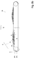
- the figures 3a , b, 4a, b show a first design of the overlapping unit 30 in plan view and in side view.
- the overlapping unit 30 has two conveyor units 27a, 27b running next to one another - which can be part of the removal unit 17 - each shown here as a belt conveyor, each with one endlessly circulating over two deflection rollers 31 Conveyor belt or conveyor belt, the upper run of which is driven from left to right in a general transport direction 10 in this case.
- the two conveyor units 27a, b do not run parallel to one another when viewed from above, but rather their conveying directions 10a, b viewed from above differ by a small intermediate angle ⁇ of generally less than 20°, so that the two conveyors 27a, b at the Beginning of their transport route, in Figure 3a left, have a distance to each other when viewed from above, but at the end of their transport route, in Figure 3a right, have a smaller distance from one another, in particular are brought together as closely as possible.
- the two conveyors 27a, b are preferably each driven by a motor 32 and are therefore driven independently of one another, with the motors 32 being controlled by a controller 30* of the overlapping unit.
- a partial portion P1 or P2 of slices S shingled in the transport direction 10 is produced or placed on the respective support surface 27a1, 27b1 of each of the two conveyor units 27a, b, which, for example, is directly from one arranged upstream of it Slicing machine can fall off, as shown in the side view of the Figure 3b shown.
- FIG. 3b also shows that the upper strands of the two conveyors, i.e. their contact surfaces 27a1, 27b1, have a height difference H to one another at the beginning of the conveyor section, i.e. at the longitudinal position of the axes of rotation of their upstream deflection rollers 31 in the transport direction.
- the downstream deflection rollers 31 and/or the upper strands of the two conveyor units 27a, b are preferably located at the same level.
- the article A in this case the partial portion P1
- the article A is placed on the lower support surface 27a1 at the start of the transport path in such a way that the article, i.e. the slices S of the partial portion P1 , as close as possible to the corresponding edge of the bearing surface 27a1 of the conveyor 27a.
- the partial portion P2 is produced or placed, preferably in the same longitudinal position, in such a way that it even protrudes in the direction of the other conveyor 27a beyond the corresponding edge of the support surface 27b1 by an overhang Ü1, for which the slices S should of course have a certain rigidity so that they do not hang down too much.
- the two articles A such as partial portions P1, P2 are moved in the transport direction 10, preferably from the start, at the same speed, i.e. synchronously, by means of the respective conveyor unit 27a, b, then they reduce their initial height difference H more and more, until they come into contact with one another close to the downstream deflection rollers 31, i.e. the end of the transport path--as in FIG Figure 4a , b shown - in that the lateral overhang Ü1 of the partial portion P2 rests on the edge region of the adjacent partial portion P1 facing it.
- downstream deflection rollers 31 or upper strands must have no or only a small enough difference in height from one another that the two partial portions are in contact with one another, ie rest on one another.
- a subsequent conveyor 26 shown here again as a belt conveyor, which is at least across the width of the entire transversely shingled Portion, here over the width of the two belt conveyors 27a, b lying next to one another in the plan view, and picks up the overlapping entire portion and transports it away.
- FIG Figure 1c in the side view an alternative solution in which both the upstream deflection rollers 31 and the two downstream deflection rollers 31 of the two conveyors 27a, b are at the same level.
- the height difference H is generated in that the upper strand of the conveyor 27b on which the laterally protruding partial portion P2 or article A is placed is guided over a further, central deflection roller 31 in the middle area of the transport section, the upper side of which moves by the height difference H positioned above the top of the downstream and/or upstream turning roller 31 of this conveyor.
- Deflection rollers 31 for a belt conveyor belt have axially spaced circumferential grooves in their outer surface, in which one of the belts 25 runs and are thus guided in a form-fitting manner against offset in the transverse direction 11 .
- the transport directions 10a, 10b of the two belt conveyor belts in the first part of their transport route again differ from one another by an intermediate angle ⁇ and towards one another in the transport direction 10, so that at the end of these differently aligned partial transport routes preferably those facing the other belt conveyor belt first belts have the same distance from each other as the belts within one of the two belt conveyor belts.
- a further deflection roller 31 with circumferential grooves for the belts 25 is arranged as a deflection device for parallel running of all belts 25 of the two belt conveyor belts 27a, b in one of the two belt conveyor units, here 27b, the grooves therein are dimensioned relative to the cross-sectional shape of the belts 25 and the belts 25 dip so deeply into it that they do not jump out of their groove despite the deflection of each belt 25 by one of the circumferential grooves in this deflection roller 31.
- the downstream deflection roller 31 at the end of the conveying path is preferably over the entire width of the two previously separate conveying units 27a, b are designed to be continuous and this is preferably also the driven deflection roller, with all circumferential grooves therein having the same spacing in the transverse direction 11 from one another.
- Such a deflection of the conveying direction of the belts of a belt conveyor belt viewed from above is all the easier possible the smaller the extent of the cross section of the individual belt 25 in the transverse direction 11 to the height of the cross section.
- a deflection with round belts is particularly easy, i.e. belts 25 with a round cross section, as in Figure 5c shown:
- the circumferential grooves for the individual belts of the conveyor 27b are not accommodated in a common deflection roller 31, but each belt 25 is deflected by its own deflection roller 34 with a circumferential groove in its circumference.
- the deflection rollers 34 are therefore generally no longer in their axial direction than the diameter of the round belt 25, and the individual deflection rollers 24 are arranged with their axes of rotation 34' parallel to one another at a distance corresponding to the distance between the round belts 25 in the transverse direction 11.
- the respective main planes of the individual deflection rollers 34 which are perpendicular to the respective axis of rotation 34' - which are also parallel to one another - are at an angle to the bearing surface 27a1 or 27b1 of the belt conveyor at this point, so that the belt 25 does not come out of the circumferential groove of the deflection roller 34 Can slip out if it is sufficiently adapted to the peripheral contour of the round belt 25 as usual.
- the Figures 6a , b, 7a, b show a fourth design of an overlapping unit 30:
- the articles A to be overlapped, here again the partial portions P1, P2, are not arranged on the bearing surface of the upper run of an endlessly circulating belt or belt conveyor, but each of the articles A, i.e.
- each of the partial portions P1, P2 on the upper side of a carriage 24a or 24b which can in particular be driven independently of one another, which in this case are track-guided, for example by having at least two guide elements each, such as a guide roller 36, protruding downwards from the underside and offset in the transport direction 10 , which are guided in a form-fitting manner in the transverse direction 11 in a track guide 23a, b that defines the respective transport direction 10a, 10b.
- a raised component such as a bar can also be used as a track guide, and conversely, counter-guide elements can be present on the carriage 24, which act on both sides of this raised track guide 23 from the outside.
- the carriages 24 can also be moved in a controlled manner on a flat surface without grooves and elevations or other form-fitting track guidance without form-fitting guidance, either with the aid of their own driven and controlled wheels or by means of another drive system.
- the two carriages 24a, b have such a distance in the transverse direction 11 that the partial portion P2, which is also placed on one of the two carriages (here 24b) with a lateral overhang Ü1, does not come into contact with the adjacent carriage 24a and the partial portion P1 placed thereon.
- the carriages 24a, b again have a height difference H with respect to their upper side, which is preferably greater than the height h of the article A, in this case the partial portion P1, which after overlapping is the lower partial portion or article .
- the carriages 24a and 24b are moved from left to right in these figures - preferably at the same speed in the transport direction 10 - they approach one another in a region of the transport directions 10a, b, which are at an angle to one another, in the transverse direction to such an extent that in the final state according to Figure 7b viewed from above, the two partial portions P1, P2 do not overlap, and viewed from the side, the two partial portions P1, P2 rest on one another at least in the overlapping area. Since the parallel guidance of the two carriages 24, 24b is possible without any problems once this overlapping state has been reached, there is no need to transfer the overlapped total portion to a subsequent conveyor.
- Another advantage of this solution is that in the initial area of the transfer unit 30, in front of the area with an angled course of the two transport directions in 10a, 10b, these two transport directions can also run parallel, and thus when creating a shingled partial portion P1, P2 each of these carriages, the longitudinal direction of the shingled portion corresponds to the transport direction 10a, 10b and the longitudinal direction of the carriage, eg 24b, in contrast to the design Figure 3a .
- the Figures 8a , b show a top view and side view of a fifth design , with the figures showing the non-overlapped initial state and the overlapped end state next to each other in the same representation:
- the conveyor units 27a, b are again shown as belt conveyors, although these two belt conveyors have transport directions 10a, b that are parallel to one another from the start.
- the overlap is achieved in that one of the belt conveyors, here 27b, including its deflection rollers 31, can be displaced in the transverse direction 11, even when the conveyor belt is running, and one of the two belt conveyors can be displaced vertically, with preferably both movement options are realized on one and the same conveyor unit, here 27b.
Landscapes
- Engineering & Computer Science (AREA)
- Mechanical Engineering (AREA)
- Life Sciences & Earth Sciences (AREA)
- Forests & Forestry (AREA)
- Structure Of Belt Conveyors (AREA)
Applications Claiming Priority (1)
| Application Number | Priority Date | Filing Date | Title |
|---|---|---|---|
| DE102020129750.5A DE102020129750A1 (de) | 2020-11-11 | 2020-11-11 | Verfahren zum Quer-Positionieren eines zu transportierenden Artikels |
Publications (1)
| Publication Number | Publication Date |
|---|---|
| EP4001187A1 true EP4001187A1 (fr) | 2022-05-25 |
Family
ID=78528670
Family Applications (1)
| Application Number | Title | Priority Date | Filing Date |
|---|---|---|---|
| EP21206389.5A Pending EP4001187A1 (fr) | 2020-11-11 | 2021-11-04 | Procédé de positionnement transversal d'un article à transporter |
Country Status (3)
| Country | Link |
|---|---|
| US (1) | US11718484B2 (fr) |
| EP (1) | EP4001187A1 (fr) |
| DE (1) | DE102020129750A1 (fr) |
Families Citing this family (3)
| Publication number | Priority date | Publication date | Assignee | Title |
|---|---|---|---|---|
| EP4347454A1 (fr) * | 2021-05-31 | 2024-04-10 | Körber Supply Chain Logistics GmbH | Rétrécissement d'un flux transporté de marchandises de détail |
| DE102022113919A1 (de) | 2022-06-02 | 2023-12-07 | Multivac Sepp Haggenmüller Se & Co. Kg | Nadelgelagerte Umlenkwalze sowie damit ausgestattete Aufschneide-Maschine |
| DE102023112461A1 (de) * | 2023-05-11 | 2024-11-14 | Multivac Sepp Haggenmüller Se & Co. Kg | Verfahren zum Erstellen von verlängerten Produkt-Kalibern sowie Aufschneide-Maschine zum Aufschneiden dieser Produkt-Kaliber |
Citations (3)
| Publication number | Priority date | Publication date | Assignee | Title |
|---|---|---|---|---|
| US20040016331A1 (en) * | 2002-07-26 | 2004-01-29 | Formax, Inc. | Automatic draft length compensation for slicing machine system |
| DE102014106400A1 (de) * | 2014-04-25 | 2015-11-12 | Weber Maschinenbau Gmbh Breidenbach | Individueller transport von lebensmittelportionen |
| DE102015104055A1 (de) | 2015-03-18 | 2016-09-22 | Textor Maschinenbau GmbH | Überlappungsvorrichtung |
Family Cites Families (11)
| Publication number | Priority date | Publication date | Assignee | Title |
|---|---|---|---|---|
| US4645061A (en) * | 1985-02-26 | 1987-02-24 | Welch Hubert E | Machine for stacking nestable extruded cans |
| EP0274229B1 (fr) * | 1986-12-10 | 1991-10-02 | Thurne Engineering Co Ltd | Système de transport |
| DE3726254A1 (de) | 1987-08-07 | 1989-02-16 | Hans Schiessl | Uebergangsfoerderstrecke zum zusammenfuehren, auseinanderfuehren, sortieren oder kanalisieren von transportgegenstaenden in einer foerderanlage |
| DE4220602C2 (de) | 1992-04-29 | 2001-02-22 | Maschb Heinrich Hajek Gmbh & C | Schneidemaschine zum Schneiden von Lebensmittelprodukten mit längenverstellbarem Transportband |
| US6935215B2 (en) * | 2002-08-14 | 2005-08-30 | Formax, Inc. | Slicing machine and conveyor system with automatic product width compensation |
| US7104388B2 (en) * | 2004-08-26 | 2006-09-12 | Arr Tech, Inc. | Conveyor system for stacked product |
| DE102013206138A1 (de) * | 2013-04-08 | 2014-10-09 | Weber Maschinenbau Gmbh Breidenbach | Vorrichtung zum Komplettieren eines Formatsatzes von Produkten |
| DE102013223494A1 (de) * | 2013-11-18 | 2015-05-21 | Robert Bosch Gmbh | Produktstromüberführungsvorrichtung |
| DE102014113738A1 (de) | 2014-09-23 | 2016-03-24 | Weber Maschinenbau Gmbh Breidenbach | Vorrichtung zum zusammenführen von portionen |
| DE102017100620A1 (de) | 2017-01-13 | 2018-07-19 | Weber Maschinenbau Gmbh Breidenbach | Produktgreifer |
| US11198565B2 (en) * | 2019-02-19 | 2021-12-14 | Provisur Technologies, Inc. | Multi-presentation slicing conveyor apparatus |
-
2020
- 2020-11-11 DE DE102020129750.5A patent/DE102020129750A1/de active Pending
-
2021
- 2021-11-04 EP EP21206389.5A patent/EP4001187A1/fr active Pending
- 2021-11-10 US US17/523,159 patent/US11718484B2/en active Active
Patent Citations (3)
| Publication number | Priority date | Publication date | Assignee | Title |
|---|---|---|---|---|
| US20040016331A1 (en) * | 2002-07-26 | 2004-01-29 | Formax, Inc. | Automatic draft length compensation for slicing machine system |
| DE102014106400A1 (de) * | 2014-04-25 | 2015-11-12 | Weber Maschinenbau Gmbh Breidenbach | Individueller transport von lebensmittelportionen |
| DE102015104055A1 (de) | 2015-03-18 | 2016-09-22 | Textor Maschinenbau GmbH | Überlappungsvorrichtung |
Also Published As
| Publication number | Publication date |
|---|---|
| US20220144559A1 (en) | 2022-05-12 |
| DE102020129750A1 (de) | 2022-05-12 |
| US11718484B2 (en) | 2023-08-08 |
Similar Documents
| Publication | Publication Date | Title |
|---|---|---|
| EP3170632B1 (fr) | Dispositif et procédé destinés au découpage de produits alimentaires | |
| EP4001187A1 (fr) | Procédé de positionnement transversal d'un article à transporter | |
| DE3008842C2 (fr) | ||
| EP3246260B1 (fr) | Dispositif de guidage de chariots à produits et dispositif destiné à faire pivoter une section de recouvrement d'un chariot à produits | |
| EP3277605B1 (fr) | Convoyeur à bande à auges pour transporter des poissons de manière transversale par rapport à leur extension longitudinale dans une direction de transport, ensemble et procédé | |
| DE102022106471A1 (de) | Einlege-Zufuhreinheit sowie Verfahren für ihren Betrieb | |
| DE102021102247A1 (de) | Verfahren zum Falten einer abgetrennten Scheibe sowie hierfür ausgebildete Aufschneide-Maschine | |
| EP4286117A1 (fr) | Couteau, unité de coupe et machine à découper | |
| EP4032669A1 (fr) | Machine à trancher à plusieurs pistes pourvue de pinces à commande indépendante | |
| DE102019100631B3 (de) | Sortierer | |
| EP4000829A1 (fr) | Procédé de positionnement d'un article à transporter, ainsi que dispositif de mise en uvre du procédé | |
| EP0867263A2 (fr) | Système d'alimentation de produits dans une machine à débiter en tranches | |
| EP0739834A2 (fr) | Dispositif pour tourner des produits pendant le processus de transport | |
| EP3380419B1 (fr) | Procédé et dispositif de mise en portions de tranches d'un produit alimentaire avec modification de forme, notamment pliage, de la portion | |
| EP1351783A1 (fr) | Dispositif de coupe transversale de bandes metalliques | |
| DE4413008A1 (de) | Faltvorrichtung für Blattlagen | |
| DE69723654T2 (de) | Vorrichtung und Verfahren zum Formen eines kontinuierlichen Teigstreifens | |
| DE102020133580A1 (de) | Aufschneide-Maschine | |
| WO2012025093A1 (fr) | Procédé de transfert contrôlé d'un colis de détail d'un transporteur d'arrivage de marchandises à un transporteur | |
| EP2298514B1 (fr) | Procédé et dispositif de coupe d'un tronçon d'aliments en tranches | |
| DE102023103039A1 (de) | Aufschneide-Maschine | |
| EP3377282B1 (fr) | Procédé de formation de portion de manière indépendante à partir de tranches de produits alimentaires dans plusieurs voies | |
| EP2984009B1 (fr) | Dispositif de conservation limitée dans le temps d'objets | |
| DE102021100897A1 (de) | Aufschneide-Maschine | |
| DE102020133162A1 (de) | Aufschneide-Maschine |
Legal Events
| Date | Code | Title | Description |
|---|---|---|---|
| PUAI | Public reference made under article 153(3) epc to a published international application that has entered the european phase |
Free format text: ORIGINAL CODE: 0009012 |
|
| STAA | Information on the status of an ep patent application or granted ep patent |
Free format text: STATUS: THE APPLICATION HAS BEEN PUBLISHED |
|
| STAA | Information on the status of an ep patent application or granted ep patent |
Free format text: STATUS: REQUEST FOR EXAMINATION WAS MADE |
|
| AK | Designated contracting states |
Kind code of ref document: A1 Designated state(s): AL AT BE BG CH CY CZ DE DK EE ES FI FR GB GR HR HU IE IS IT LI LT LU LV MC MK MT NL NO PL PT RO RS SE SI SK SM TR |
|
| 17P | Request for examination filed |
Effective date: 20220517 |
|
| RBV | Designated contracting states (corrected) |
Designated state(s): AL AT BE BG CH CY CZ DE DK EE ES FI FR GB GR HR HU IE IS IT LI LT LU LV MC MK MT NL NO PL PT RO RS SE SI SK SM TR |
|
| STAA | Information on the status of an ep patent application or granted ep patent |
Free format text: STATUS: EXAMINATION IS IN PROGRESS |
|
| 17Q | First examination report despatched |
Effective date: 20230525 |
|
| P01 | Opt-out of the competence of the unified patent court (upc) registered |
Effective date: 20230519 |