EP4001192A1 - Fadenschneide- und ansaugvorrichtung - Google Patents
Fadenschneide- und ansaugvorrichtung Download PDFInfo
- Publication number
- EP4001192A1 EP4001192A1 EP21207723.4A EP21207723A EP4001192A1 EP 4001192 A1 EP4001192 A1 EP 4001192A1 EP 21207723 A EP21207723 A EP 21207723A EP 4001192 A1 EP4001192 A1 EP 4001192A1
- Authority
- EP
- European Patent Office
- Prior art keywords
- yarn
- blade part
- yarns
- guide
- cutter
- Prior art date
- Legal status (The legal status is an assumption and is not a legal conclusion. Google has not performed a legal analysis and makes no representation as to the accuracy of the status listed.)
- Granted
Links
Images


Classifications
-
- B—PERFORMING OPERATIONS; TRANSPORTING
- B65—CONVEYING; PACKING; STORING; HANDLING THIN OR FILAMENTARY MATERIAL
- B65H—HANDLING THIN OR FILAMENTARY MATERIAL, e.g. SHEETS, WEBS, CABLES
- B65H54/00—Winding, coiling, or depositing filamentary material
- B65H54/70—Other constructional features of yarn-winding machines
- B65H54/71—Arrangements for severing filamentary materials
-
- D—TEXTILES; PAPER
- D01—NATURAL OR MAN-MADE THREADS OR FIBRES; SPINNING
- D01D—MECHANICAL METHODS OR APPARATUS IN THE MANUFACTURE OF ARTIFICIAL FILAMENTS, THREADS, FIBRES, BRISTLES OR RIBBONS
- D01D13/00—Complete machines for producing artificial threads
- D01D13/02—Elements of machines in combination
-
- B—PERFORMING OPERATIONS; TRANSPORTING
- B65—CONVEYING; PACKING; STORING; HANDLING THIN OR FILAMENTARY MATERIAL
- B65H—HANDLING THIN OR FILAMENTARY MATERIAL, e.g. SHEETS, WEBS, CABLES
- B65H54/00—Winding, coiling, or depositing filamentary material
- B65H54/86—Arrangements for taking-up waste material before or after winding or depositing
- B65H54/88—Arrangements for taking-up waste material before or after winding or depositing by means of pneumatic arrangements, e.g. suction guns
-
- B—PERFORMING OPERATIONS; TRANSPORTING
- B65—CONVEYING; PACKING; STORING; HANDLING THIN OR FILAMENTARY MATERIAL
- B65H—HANDLING THIN OR FILAMENTARY MATERIAL, e.g. SHEETS, WEBS, CABLES
- B65H57/00—Guides for filamentary materials; Supports therefor
- B65H57/16—Guides for filamentary materials; Supports therefor formed to maintain a plurality of filaments in spaced relation
-
- D—TEXTILES; PAPER
- D06—TREATMENT OF TEXTILES OR THE LIKE; LAUNDERING; FLEXIBLE MATERIALS NOT OTHERWISE PROVIDED FOR
- D06H—MARKING, INSPECTING, SEAMING OR SEVERING TEXTILE MATERIALS
- D06H7/00—Apparatus or processes for cutting, or otherwise severing, specially adapted for the cutting, or otherwise severing, of textile materials
- D06H7/02—Apparatus or processes for cutting, or otherwise severing, specially adapted for the cutting, or otherwise severing, of textile materials transversely
-
- B—PERFORMING OPERATIONS; TRANSPORTING
- B65—CONVEYING; PACKING; STORING; HANDLING THIN OR FILAMENTARY MATERIAL
- B65H—HANDLING THIN OR FILAMENTARY MATERIAL, e.g. SHEETS, WEBS, CABLES
- B65H2701/00—Handled material; Storage means
- B65H2701/30—Handled filamentary material
- B65H2701/31—Textiles threads or artificial strands of filaments
- B65H2701/313—Synthetic polymer threads
- B65H2701/3132—Synthetic polymer threads extruded from spinnerets
-
- B—PERFORMING OPERATIONS; TRANSPORTING
- B65—CONVEYING; PACKING; STORING; HANDLING THIN OR FILAMENTARY MATERIAL
- B65H—HANDLING THIN OR FILAMENTARY MATERIAL, e.g. SHEETS, WEBS, CABLES
- B65H2701/00—Handled material; Storage means
- B65H2701/30—Handled filamentary material
- B65H2701/38—Thread sheet, e.g. sheet of parallel yarns or wires
Definitions
- the present invention relates to a yarn cutting-sucking device.
- Patent Literature 1 Japanese Unexamined Patent Publication No. 2012-180610 discloses a yarn cutting-sucking device including a cutter movable in an arrangement direction in which yarns are aligned and a sucking unit which is provided to be close to the cutter, is movable in the arrangement direction in the same manner as the cutter, and is configured to suck the yarns cut by the cutter.
- the running yarns are cut one by one in such a way that the cutter is caused to move in the arrangement direction of the yarns. Because of this, all yarns are cut regardless of the number of the yarns.
- An object of the present invention is to provide a yarn cutting-sucking device capable of further reliably cutting and sucking yarns which run while being aligned in an arrangement direction.
- a yarn cutting-sucking device is configured to cut and suck yarns which run in a yarn running direction while being aligned in an arrangement direction
- the yarn cutting-sucking device including: a cutter which includes a blade part for cutting each of the yarns; a sucking section which is movable together with the cutter and which is configured to suck the yarns cut by the cutter; a first guide which is provided upstream of the cutter in the yarn running direction, which moves together with the cutter, and which is configured to guide each of the yarns to the blade part; and a second guide which is provided downstream of the cutter in the yarn running direction, which moves together with the cutter, and which is configured to guide each of the yarns to the blade part, when the cutter cuts the yarns, a relative position of the cutter to the yarns moving from one side toward the other side in the arrangement direction
- the first guide including a first regulatory portion which regulates movement of each of the yarns in a direction in which each of the yarns is pushed as a result
- the yarn cutting-sucking device of the first aspect is arranged such that the first guide has a first guide groove for directing each of the yarns to the blade part, the second guide has a second guide groove for directing each of the yarns to the blade part, and a part of an inner side surface of the first guide groove forms the first regulatory portion while a part of an inner side surface of the second guide groove forms the second regulatory portion.
- the yarns are further reliably directed to the blade part by the first guide groove and the second guide groove, and hence the yarns which run while being aligned in the arrangement direction are further reliably cut and sucked.
- the yarn cutting-sucking device of the first or second aspect is arranged such that, when the blade part is viewed in the yarn running direction, an angle between an extending direction of the blade part at a contact point with each of the yarns and a direction in which each of the yarns is guided by the first guide and the second guide is 45 degrees or more and 90 degrees or less.
- the force which is transmitted from the blade part to each yarn at the time of cutting the yarns is increased as compared to cases where the angle between the extending direction of the blade part at the contact point with each yarn in the yarn running direction and the direction in which each yarn is guided by the first guide and the second guide is less than 45 degrees. Because of this, the running yarns are further reliably cut.
- the yarn cutting-sucking device of the first or second aspect is arranged such that the blade part linearly extends so that a first end of the blade part on the other side in the arrangement direction is on one side in an orthogonal direction as compared to a second end of the blade part on one side in the arrangement direction, the orthogonal direction being orthogonal to the yarn running direction and the arrangement direction, and when the blade part is viewed in the yarn running direction, an angle between the extending direction of the blade part at the contact point with each of the yarns and the direction in which each of the yarns is guided by the first guide and the second guide is 10 degrees or more and 90 degrees or less on one side in the orthogonal direction.
- the yarns are further properly guided to the blade part, which extends to be inclined from the orthogonal direction when viewed in the yarn running direction, as compared to cases where the angle between (i) the extending direction of the blade part at the contact point with each yarn when viewed in the yarn running direction and (ii) the direction in which each yarn is guided is more than 90 degrees or less than 10 degrees on one side in the orthogonal direction. Because of this, the running yarns are further reliably cut.
- the yarn cutting-sucking device of the third or fourth aspect is arranged such that the blade part linearly extends so that the first end of the blade part on the other side in the arrangement direction is on an upstream side or a downstream side in the yarn running direction of the second end of the blade part on one side in the arrangement direction.
- the blade part is pressed on each of the running yarns while the extending direction of the blade part is inclined from the yarn running direction. Therefore, the blade part further smoothly enters and cuts each of the running yarns as compared to cases where the blade part is pressed on each of the running yarns so that an angle between the extending direction of the blade part and the yarn running direction is 90 degrees.
- the yarn cutting-sucking device of any one of the first to fifth aspects is arranged such that the blade part is formed so that a contact part with each of the yarns varies during a period until each of the yarns is cut after making contact with the blade part.
- the yarn cutting-sucking device of the sixth aspect is arranged such, when the blade part is viewed in the arrangement direction, an inclination angle between the extending direction of the blade part and the yarn running direction is 25 degrees or more and 45 degrees or less.
- the yarn moves along the blade part in which the inclination angle between the extending direction and the yarn running direction is 25 degrees or more and 45 degrees or less when viewed in the arrangement direction. Because of this, the running yarns are cut while the burden on the blade part is reduced.
- the yarn cutting-sucking device of any one of the first to seventh aspects is arranged such that the cutter is formed of one blade having the blade part.
- a yarn cutting-sucking device is able to further reliably cut and suck yarns which run while being aligned in an arrangement direction.
- FIG. 1 schematically shows a spun yarn take-up machine 1.
- the spun yarn take-up machine 1 includes a spinning apparatus 2, an oil supply guide 3, two godet rollers 4a and 4b, and a yarn winding apparatus 5.
- an up-down direction and a left-right direction shown in FIG. 1 will be referred to as an up-down direction and a front-rear direction.
- a direction perpendicular to the sheet of FIG. 1 will be referred to a left-right direction
- a direction toward the viewer of FIG. 1 will be referred to as a rightward direction.
- the spun yarn take-up machine 1 causes the oil supply guide 3 to apply oil to yarns Y which are continuously spun out from a spinneret 2a of the spinning apparatus 2, and then causes the two godet rollers 4a and 4b to draw the yarns Y. Subsequently, the yarns Y are sent to the yarn winding apparatus 5, which is provided below the godet rollers 4a and 4b, and wound by the yarn winding apparatus 5.
- a molten fibrous material such as polyester is continuously spun out downward form the spinneret 2a of the spinning apparatus 2, as the yarns Y formed of filaments F.
- the oil supply guide 3 is provided below the spinning apparatus 2, and configured to apply oil to the yarns Y spun out from the spinning apparatus 2.
- the oil supply guide 3 also regulates intervals between the yarns Y to be identical with one another in the left-right direction (i.e., arrangement direction of the present invention).
- a yarn regulating guide 30 is provided below the oil supply guide 3 and above the godet roller 4a.
- the yarn regulating guide 30 is a comb-teeth-shaped guide including guide pieces 30a which are aligned in the arrangement direction of the yarns Y.
- the guide pieces 30a extend from the front side toward the rear side in the front-rear direction.
- the yarns Y supplied from the spinning apparatus 2 pass through the respective intervals between the guide pieces 30a. Because of this, the intervals between the yarns Y are regulated to be identical with one another in the left-right direction, i.e., the arrangement direction of the yarns Y.
- the yarns Y to which oil has been applied are taken up by the two godet rollers 4a and 4b, and are sent to the yarn winding apparatus 5 provided below the two godet rollers 4a and 4b.
- the godet roller 4b is provided above, behind, and on the downstream of the godet roller 4a in a yarn running direction in which the yarns Y run.
- the two godet rollers 4a and 4b are driven by unillustrated drive motors.
- the yarn winding apparatus 5 is configured to wind the yarns Y and includes members such as: fulcrum guides 11 to which the yarns Y sent from the godet roller 4b are respectively distributed; traverse guides 12 by which the yarns Y distributed to the fulcrum guides 11 are respectively traversed; two bobbin holders 13 to each of which bobbins B are attached to be aligned along the axis; a turret 14 which is disc-shaped and which supports one end of each bobbin holder 13; a main body frame 15 which rotatably supports the turret 14; and a contact roller 16 which is movable in the up-down direction with respect to the main body frame 15 and which is separated from the bobbins B attached to the bobbin holders 13.
- members such as: fulcrum guides 11 to which the yarns Y sent from the godet roller 4b are respectively distributed; traverse guides 12 by which the yarns Y distributed to the fulcrum guides 11 are respectively traversed; two bobbin holders 13
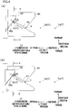
- the yarn cutting-sucking device 40 As shown in FIG. 1 and FIG. 2 , the yarn cutting-sucking device 40 is provided below the oil supply guide 3, immediately upstream of the yarn regulating guide 30 in the yarn running direction, and to the left of yarn paths of the yarns Y running from the upstream side toward the downstream side in the yarn running direction while being aligned in the left-right direction. As shown in FIG. 3 , the yarn cutting-sucking device 40 includes a holder 41, a cutter 42, a sucking unit 43, a first guide 44, and a second guide 45. The holder 41 is the base of the yarn cutting-sucking device 40.
- the sucking unit 43 is configured to suck the yarns Y which are cut by the cutter 42.
- the sucking unit 43 includes a cylindrical member 51 (equivalent to a sucking section of the present invention), an air cylinder (not illustrated), etc.
- a right end portion of the cylindrical member 51 protrudes from an opening portion 41a of the holder 41.
- the cylindrical member 51 is connected to a sucking power source 71 shown in FIG. 1 , and sucking force for sucking the cut yarns Y is generated at a right tip end of the cylindrical member 51.
- the cut yarns Y are sucked through a suction port 51a at the right tip end of the cylindrical member 51.
- the cylindrical member 51 is connected to the sucking power source 71 via an electromagnetic valve (not illustrated).
- the air cylinder (not illustrated) is provided in the holder 41.
- a cylinder rod (not illustrated) is attached to the air cylinder.
- the cylinder rod is connected to the cylindrical member 51.
- the air cylinder is driven by a driving unit 70 shown in FIG. 1 so that the cylinder rod moves, with the result that the cylindrical member 51 moves in the arrangement direction (i.e., left-right direction) of the yarns Y.
- the left side in the left-right direction corresponds to one end side in the arrangement direction of the present invention while the right side in the left-right direction corresponds to the other side in the arrangement direction of the present invention.
- the cutter 42 is configured to cut the yarns Y, which are provided above the yarn regulating guide 30, one by one or at once as shown in, e.g., FIG. 7 at the time of rightward movement of the cylindrical member 51. As shown in FIG. 2 and FIG. 3 , the cutter 42 is attached to a lower portion of the right tip end of the cylindrical member 51 via a cutter holding portion 48. Because of this, as the cylindrical member 51 moves rightward, the cutter 42 also moves rightward toward the yarns Y.
- the cutter 42 is a plate member including one blade part 42a for cutting the yarns Y.
- the cutter 42 is formed of one blade.
- the blade part 42a linearly extends along an edge line of the cutter 42. As shown in FIG. 3 , the blade part 42a linearly extends so that, in the up-down direction, one end of the blade part 42a on the left side in the left-right direction (i.e., left end of the blade part 42a) is lower than the other end of the blade part 42a on the right side in the left-right direction (i.e., right end of the blade part 42a).
- an inclination angle ⁇ 1 between the extending direction of the blade part 42a and the up-down direction is, e.g., 25 degrees or more and 45 degrees or less.
- the up-down direction substantially corresponds to the yarn running direction in the vicinity of the yarn cutting-sucking device 40.
- the blade part 42a linearly extends so that, in the up-down direction, one end of the blade part 42a on the rear side is higher than the other end of the blade part 42a on the front side in the front-rear direction.
- an inclination angle ⁇ 3 between the extending direction of the blade part 42a and the up-down direction is 25degrees or more and 45 degrees or less (see FIG. 5 ) . Furthermore, because the blade part 42a has these inclination angles ⁇ 1 and ⁇ 3, the blade part 42a linearly extends so that the right end is on the rear side in the front-rear direction as compared to the left end when viewed in the up-down direction (see FIGs. 4(a) and (b) ).
- the first guide 44 and the second guide 45 are configured to guide the yarns Y to the blade part 42a of the cutter 42.
- the first guide 44 is provided upstream of the cutter 42 in the yarn running direction, and attached to the lower portion of the right tip end of the cylindrical member 51 via the cutter holding portion 48.
- the second guide 45 is provided downstream of the cutter 42 in the yarn running direction, and attached to the lower portion of the right tip end of the cylindrical member 51 via the cutter holding portion 48. Because of this, as the cylindrical member 51 moves rightward, the first guide 44 and the second guide 45 also move rightward toward the yarns Y. In other words, the cutter 42, the sucking unit 43, the first guide 44, and the second guide 45 are movable together with the cylindrical member 51 in the left-right direction.
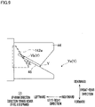
- the first guide 44 when viewed in the up-down direction, has a first guide groove 46 which is open to the right side in the left-right direction and which linearly extends leftward and rearward from this opening.
- the second guide 45 When viewed in the up-down direction, has a second guide groove 47 which is open to the right side in the left-right direction and which linearly extends leftward and rearward from this opening.
- the yarns Y aligned in the left-right direction are directed one by one toward the blade part 42a by the first guide groove 46 and the second guide groove 47.
- the extending direction of the first guide groove 46 and the second guide groove 47 is the direction in which each yarn Y is directed by the first guide groove 46 and the second guide groove 47.
- the blade part 42a linearly extends from the left side (i.e., one side) toward the right side (i.e., the other side) in the left-right direction (i.e., arrangement direction) so that the right end is on the rear side (equivalent to one side in an orthogonal direction of the present invention) in the front-rear direction (equivalent to the orthogonal direction of the present invention) as compared to the left end. As shown in FIGs.
- an angle ⁇ 2 between the extending direction of the linear blade part 42a and the extending direction of the first guide groove 46 and the second guide groove 47 is 45 degrees or more and to 90 degrees or less on the rear side (equivalent to one side in the orthogonal direction of the present invention) in the front-rear direction. Because of this, the force which is transmitted from the blade part 42a to each yarn Y at the time of cutting the yarns Y is increased. As a result, the running yarns Y are further reliably cut. In addition to that, the yarns Y are further properly guided to the blade part 42a which extends to be inclined from the front-rear direction when viewed in the up-down direction.
- the blade part 42a When viewed in the up-down direction, the blade part 42a linearly extends so that the right end is on the rear side in the front-rear direction as compared to the left end.
- the contact with this blade part 42a results in pushing of each yarn Y, which is guided to this blade part 42a, toward the right side and the front side in the left-right direction and the front-rear direction as compared to the blade part 42a.
- a part i.e., painted part in FIG.
- each yarn Y which is not guided by the first guide groove 46 and the second guide groove 47 is defined as a yarn Ya
- each yarn Y which has been guided by the first guide groove 46 and the second guide groove 47 is defined as a yarn Yb.
- the cylindrical member 51 is provided at a position on the holder 41 side as compared to the yarns Y, and the right tip end of the cylindrical member 51, the cutter 42, the first guide 44, and the second guide 45 are also provided on the holder 41 side as compared to the yarns Y.
- the yarn cutting-sucking device 40 is driven automatically or is manually by an operator.
- the electromagnetic valve (not illustrated) is open and the cylindrical member 51 is connected to the sucking power source 71, the yarn cutting-sucking device 40 starts to suck the yarns Y.
- an arrow in the cylindrical member 51 indicates the direction in which the sucking force acts.
- the cylinder rod of the air cylinder elongates. Because of this, the cylindrical member 51 connected to this air cylinder moves rightward. As the cylindrical member 51 moves rightward, the cutter 42, the first guide 44, and the second guide 45 which are attached to the cylindrical member 51 also move rightward, i.e., toward the side where yarns Ya are aligned. Because of this, as shown in FIGs. 4(a) and 4(b) , the leftmost yarn Ya among the yarns Ya aligned in the left-right direction is guided to the first guide groove 46 and the second guide groove 47 through the openings formed in the first guide groove 46 and the second guide groove 47.
- each yarn Yb having been guided by the first guide groove 46 and the second guide groove 47 moves rearward and leftward (see solid arrows in FIGs. 4(a) and 4(b) ) along the first guide groove 46 and the second guide groove 47.
- a yarn path of each yarn Ya which is not guided by the first guide groove 46 and the second guide groove 47 is defined by the oil supply guide 3 and the yarn regulating guide 30. Meanwhile, as shown in FIGs. 4(a) and 4(b) , because the first guide groove 46 and the second guide groove 47 extend leftward and rearward when viewed in the up-down direction, a yarn path of each yarn Yb having been guided by the first guide groove 46 and the second guide groove 47 is positioned on the rear side in the front-rear direction as compared to the yarn path of each yarn Ya.
- the yarn path of each yarn Yb is defined by the oil supply guide 3 and a front inner-side surface (i.e., inner side surface on the front side in the front-rear direction) of the first guide groove 46 on the upstream of the first guide 44 in the yarn running direction, is defined by the front inner-side surface of the first guide groove 46 and a front inner-side surface of the second guide groove 47 between the first guide 44 and the second guide 45, and is defined by the front inner-side surface of the second guide groove 47 and the yarn regulating guide 30 on the downstream of the second guide 45 in the yarn running direction.
- a front inner-side surface i.e., inner side surface on the front side in the front-rear direction
- the cylindrical member 51 moves rightward while each yarn Yb is at the first guide groove 46 and the second guide groove 47, the yarn Yb makes contact with the blade part 42a. Subsequently, in order to cut the yarn Yb by the blade part 42a, the cylindrical member 51 moves further rightward while the yarn Yb is in contact with the blade part 42a. At this time, the yarn Yb tends to be pushed forward and rightward from the blade part 42a as a result of the contact with the blade part 42a.
- the part (i.e., painted part in FIG. 4(a) ) of the inner side surface of the first guide groove 46 and the part (i.e., painted part in FIG. 4(b) ) of the inner side surface of the second guide groove 47 regulate the forward and rightward movement of the yarn Yb from the blade part 42a.
- the yarn Yb which is provided downstream of the contact part between the yarn Yb and the blade part 42a in the yarn running direction, makes contact with a rear inner-side surface (i.e., inner side surface on the rear side in the front-rear direction) of the second guide groove 47.
- the yarn Yb running on the upstream of the blade part 42a in the yarn running direction is hooked by the part (i.e., painted part in FIG. 4(a) ) of the front inner-side surface of the first guide groove 46, which is in the vicinity of the blade part 42a and which is on the right side in the left-right direction as compared to the blade part 42a. Because of this, among a yarn path of the yarn Yb provided upstream of the blade part 42a in the yarn running direction, only a yarn path of the yarn Yb between the blade part 42a and the first guide groove 46 moves forward and rightward. As a result, the movement of a yarn path of the yarn Yb provided between the first guide groove 46 and the oil supply guide 3 is regulated.
- the yarn Yb running on the downstream of the blade part 42a in the yarn running direction is hooked by the part (i.e., painted part in FIG. 4(b) ) of the rear inner-side surface of the second guide groove 47, which is in the vicinity of the blade part 42a and which is on the right side in the left-right direction as compared to the blade part 42a. Because of this, among a yarn path of the yarn Yb provided downstream of the blade part 42a in the yarn running direction, only a yarn path of the yarn Yb between the blade part 42a and the second guide groove 47 moves forward and rightward. As a result, the movement of a yarn path of the yarn Yb between the second guide groove 47 and the yarn regulating guide 30 is regulated.
- the forward and rightward movement of each yarn Yb making contact with the blade part 42a is regulated as described above.
- the forward and rightward direction is the direction in which each yarn Y is pushed by the blade part 42a.
- the blade part 42a is formed to linearly extend so that one end on the front side is lower than the other end on the rear side in the front-rear direction and the up-down direction.
- the inclination angle ⁇ 3 of the blade part 42a with respect to the up-down direction is 25 degrees or more and 45 degrees or less (see FIG. 5 ). Because of this, during a period until each yarn Yb is cut after making contact with the blade part 42a, the contact part between the blade part 42a and each yarn Yb is moved downward and forward along an inclination of the blade part 42a when viewed in the left-right direction.
- the yarn cutting-sucking device 40 of the present embodiment is configured to cut and suck the yarns Y which run in the yarn running direction while being aligned in the left-right direction (i.e., the arrangement direction), and includes the following members: the cutter 42 which includes the blade part 42a for cutting the yarns Y and which is movable from the left side toward the right side in the left-right direction; the cylindrical member 51 (i.e., sucking section) which is movable together with the cutter 42 and which is configured to suck the yarns Y cut by the cutter 42; the first guide 44 which is provided upstream of the cutter 42 in the yarn running direction, which moves together with the cutter 42, and which guides the yarns Y to the blade part 42a; and the second guide 45 which is provided downstream of the cutter 42 in the yarn running direction, which moves together with the cutter 42, and which guides the yarns Y to the blade part 42a.
- the cutter 42 which includes the blade part 42a for cutting the yarns Y and which is movable from the left side
- the first guide 44 has the first regulatory portion which regulates the movement of the yarns Y in the direction in which the yarns Y are pushed as a result of the contact with the blade part 42a
- the second guide 45 has the second regulatory portion which regulates the movement of the yarns Y in the direction in which the yarns Y are pushed as a result of the contact with the blade part 42a.
- the first guide 44 has the first guide groove 46 for directing the yarns Y toward the blade part 42a while the second guide 45 has the second guide groove 47 for directing the yarns Y toward the blade part 42a.
- the part of the inner side surface of the first guide groove 46 forms the first regulatory portion
- the part of the inner side surface of the second guide groove 47 forms the second regulatory portion.
- the yarns Y are further reliably directed to the blade part 42a by the first guide groove 46 and the second guide groove 47, and hence the yarns Y which run while being aligned in the left-right direction are further reliably cut and sucked.
- the angle ⁇ 2 between (i) the extending direction of the blade part 42a at a contact point with each yarn Y and (ii) the direction in which each yarn Y is directed by the first guide groove 46 of the first guide 44 and the second guide groove 47 of the second guide 45 is 45 degrees or more and 90 degrees or less.
- each yarn Y when viewed in the yarn running direction, is pressed on the blade part 42a so that an angle between the extending direction of the blade part 42a and the direction in which each yarn Y is directed by the first guide 44 and the second guide 45 is 45 degrees or more and 90 degrees or less. Therefore, the force transmitted from the blade part 42a to each yarn Y at the time of cutting the yarn Y is increased. Because of this, the running yarns Y are further reliably cut.
- the blade part 42a linearly extends so that the right end is on the rear side (i.e., one side of the orthogonal direction) in the front-rear direction as compared to the left end in the left-right direction.
- the angle ⁇ 2 between the extending direction of the blade part 42a at the contact point with each yarn Y and the direction in which the yarn Y is directed by the first guide groove 46 and the second guide groove 47 is 10 degrees or more and 90 degrees or less on the rear side in the front-rear direction.
- the yarns Y are further properly guided to the blade part 42a, which extends to be inclined from the front-rear direction when viewed in the up-down direction, as compared to cases where an angle between (i) the extending direction of the blade part 42a at the contact point with each yarn Y when viewed in the up-down direction and (ii) the direction in which the yarn Y is guided is more than 90 degrees or less than 10 degrees on the rear side in the front-rear direction. Because of this, the running yarns Y are further reliably cut.
- the blade part 42a linearly extends so that the right end is provided upstream of the left end in the left-right direction and the yarn running direction. Because of this, the blade part 42a is pressed on each of the running yarns Y while the extending direction of the blade part 42a is inclined from the yarn running direction. Therefore, the blade part 42a further smoothly enters and cuts each of the running yarns Y as compared to cases where the blade part 42a is pressed on each of the running yarns so that an angle between the extending direction of the blade part 42a and the yarn running direction is 90 degrees.
- the blade part 42a is formed so that the contact part with each yarn Y varies during the period until the yarn Y is cut after making contact with the blade part 42a.
- the degree of pushing the blade part 42a on each yarn Y regulated by the part of the inner side surface of the first guide groove 46 (i.e., the first regulatory portion) and the part of the inner side surface of the second guide groove 47 (i.e., second regulatory portion) exceeds a threshold, the yarn Y is cut.
- the amount of pushing the blade part 42a on the yarns Y required for cutting the yarns Y depends on strength of the yarns Y, etc.
- the yarn Y moves along the blade part 42a until the amount of pushing the blade part 42a on the yarn Y becomes sufficient for cutting the yarn Y. Because of this, the burden of the blade part 42a is distributed to the entire blade part 42a as compared to cases where each yarn Y is cut by using only one part of the blade part 42a. Therefore, the running yarns Y are cut while the burden on the blade part 42a is reduced.
- the inclination angle ⁇ 3 between the extending direction of the blade part 42a and the yarn running direction is 25 degrees or more and 45 degrees or less.
- the yarn Y moves along the blade part 42a in which the inclination angle ⁇ 3 between the extending direction and the yarn running direction is 25 degrees or more and 45 degrees or less when viewed in the left-right direction. Because of this, the running yarns Y are cut while the burden on the blade part 42a is reduced.
- the cutter 42 is formed of one blade having the blade part 42a. With this arrangement, cost reduction is achieved as compared to cases where the cutter 42 is formed of two or more blade parts.
- the yarn cutting-sucking device 40 is provided immediately upstream of the yarn regulating guide 30 in the yarn running direction and to the left of the yarn paths of the yarns Y which run from the upstream side toward the downstream side in the yarn running direction while being aligned in the left-right direction.
- the yarn cutting-sucking device 40 may be provided to the right of the yarn paths of the yarns Y. In this case, as the cutter 42 and sucking unit 43 of the yarn cutting-sucking device 40 move from the right side toward the left side in the left-right direction, the yarns Y are cut and sucked.
- the cutter 42, the sucking unit 43, the first guide 44, and the second guide 45 are movable together with the cylindrical member 51 in the left-right direction.
- the cutter 42, the sucking unit 43, the first guide 44, the second guide 45, and the cylindrical member 51 may not be configured to move in the left-right direction but be fixed.
- the yarn regulating guide 30 which regulates the intervals between the yarns Y to be identical with one another in the left-right direction is configured to be movable in the left-right direction.
- the yarns Y are guided to the blade part 42a by the first guide 44 and the second guide 45 in such a way that yarn regulating guide 30 moves together with the yarns Y toward the cutter 42, etc., in the left-right direction.
- a yarn gathering guide may be additionally provided for gathering the yarns Y on the side where the apparatuses such as the cutter 42 are provided in the left-right direction.
- the intervals of the yarns Y are regulated to be identical with one another in the left-right direction by the yarn regulating guide 30.
- the yarn regulating guide 30 or the yarn gathering guide may be movable in the left-right direction so that the yarns Y are moved to be close to the cutter, etc., on condition that the cutter 42, the sucking unit 43, the first guide 44, and the second guide 45 move in the left-right direction of the cylindrical member 51 to be close to the yarns Y.
- positions of the cutter 42, the sucking unit 43, the first guide 44, and the second guide 45 which are movable together with the cutter 42 relatively move from the left side toward the right side in the left-right direction, i.e., the arrangement direction.
- the blade part 42a linearly extends so that right end is on the rear side in the front-rear direction as compared to the left side.
- a blade part 142a may linearly extend so that one end of the blade part 142a on the left side (i.e., left end) is on the rear side in the front-rear direction as compared to the other end of the blade part 142a on the right side (i.e., right end) in the left-right direction.
- the front side in the front-rear direction corresponds to one side of the orthogonal direction of the present invention.
- an angle ⁇ 4 between the extending direction of the blade part 142a at a contact point with each yarn Y and the direction in which each yarn Y is directed is 10 degrees or more and 90 degrees or less on the front side in the front-rear direction.
- the yarns Y are further properly guided to the blade part 42a, which extends to be inclined from the front-rear direction when viewed in the up-down direction, as compared to cases where an angle between (i) the extending direction of the blade part 42a at the contact point with each yarn Y when viewed in the up-down direction and (ii) the direction in which each yarn Y is guided is more than 90 degrees or less than 10 degrees on the rear side in the front-rear direction. Because of this, the running yarns Y are further reliably cut. In the present modification, when viewed in the up-down direction (i.e., yarn running direction) as shown in FIG.
- the angle ⁇ 4 between the extending direction of the linear blade part 142a and the extending direction of the first guide groove 46 and the second guide groove 47 is less than 45 degrees.
- a blade part may linearly extend in the same manner as in the embodiment above so that a right end is on the rear side in the front-rear direction as compared to a left end in the left-right direction.
- an angle between the extending direction of the blade part at a contact point with each yarn Y and the direction in which each yarn Y is directed is preferably 10 degrees or more and 90 degrees or less on the rear side in the front-rear direction.
- the angle between the extending direction of the blade part at the contact point with each yarn Y and the direction in which each yarn Y is directed is preferably 45 degrees or more and 90 degrees or less in the same manner as in the embodiment above. However, this angle may be less than 45 degrees.
- the first guide 44 has the first guide groove 46 for directing the yarns Y toward the blade part 42a while the second guide 45 has the second guide groove 47 for directing the yarns Y toward the blade part 42a.
- the part of the inner side surface of the first guide groove 46 forms the first regulatory portion
- the part of the inner side surface of the second guide groove 47 forms the second regulatory portion.
- the first guide 44 may not have the first guide groove 46
- the second guide 45 may not have the second guide groove 47.
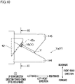
- each yarn Y may be guided to the blade part 42a along a side surface of a first guide 144 on the rear side and a side surface of a second guide 145 on the front side in the front-rear direction as shown in FIG. 10.
- FIG. 10 is a top plan view showing a right tip end of a yarn cutting-sucking device of this modification in the up-down direction, and the first guide 144 is provided to be close to the viewer of FIG. 10 as compared to the second guide 145.
- the cutter 42 is provided between these guides in the up-down direction.
- the first guide 144 and the second guide 145 are provided not to overlap each other when viewed in the up-down direction and in plan view.
- each yarn Y is guided to the blade part 42a through the gap between the rear side-surface of the first guide 144 and the front side-surface of the second guide 145. In this case, when each yarn Yb makes contact with the blade part 42a as shown in FIG. 10 and FIG.
- the yarn Yb makes contact also with a part (i.e., painted part of the first guide 144 in FIG. 10 ) of the rear side-surface of the first guide 144 and a part (i.e., painted part of the second guide 145 in FIG. 10 ) of the front side-surface of the second guide 145 in the front-rear direction. Because of this, the movement of the yarns Y is regulated in the direction in which the yarns Y are pushed as a result of the contact with the blade part 42a.
- the part of the rear side-surface of the first guide 144 in the front-rear direction corresponds to the first regulatory portion
- the part of the front side-surface of the second guide 145 in the front-rear direction corresponds to the second regulatory portion.
- only one of the first guide 44 and the second guide 45 may have a guide groove.
- the movement of the yarns Y in the direction in which the yarns Y are pushed as a result of the contact with the blade part 42a is regulated by (i) a part of an inner side surface of the guide groove provided in one of the first guide 44 and the second guide 45 and (ii) a part of a side surface of the other of the first guide groove 44 and the second guide groove 45.
- this regulation includes fixation of the movement of the yarns Y in the direction in which the yarns Y are pushed, and suppression of the movement of the yarns Y.
- the angle ⁇ 2 between the extending direction of the linear blade part 42a and the direction in which the yarns Y are directed by the first guide groove 46 and the second guide groove 47 is 45 degrees or more and 90 degrees or less.
- the angle ⁇ 2 may be less than 45 degrees.
- first guide groove 46 and the second guide groove 47 linearly extend.
- each of the first guide groove 46 and the second guide groove 47 may be curved or may be bent at an intermediate part.
- an angle between the extending direction of a straight line at a contact point between the blade part 42a and each yarn Y and the direction in which each yarn Y is directed by the first guide groove 46 and the second guide groove 47 in the vicinity of the blade part 42a is preferably 45 degrees or more and 90 degrees or less.
- the first guide 44 and the second guide 45 may not have the first guide groove 46 and the second guide groove 47.
- an angle between the extending direction of the linear blade part 42a and the direction in which each yarn Y is guided by the side surface of the first guide 44 and the side surface of the second guide 45 is preferably 45 degrees or more and 90 degrees or less.
- the blade part 42a may not linearly extend but be curved.
- an angle between the extending direction of a tangent at a contact point between the blade part 42a and each yarn Y and the direction in which each yarn Y is directed by the first guide groove 46 and the second guide groove 47 is preferably 45 degrees or more and 90 degrees or less.
- the angle between the extending direction of the blade part 42a at the contact point with each yarn Y and the direction in which each yarn Y is guided by the first guide 44 and the second guide 45 is preferably 45 degrees or more and 90 degrees or less.
- the cutter 42 is formed of one blade, i.e., the blade part 42a.
- the cutter 42 may be formed of two or more blade parts.
- the first guide groove 46 and the second guide groove 47 linearly extend leftward and rearward from the opening which is open to the right side in the left-right direction.
- the first guide groove 46 and the second guide groove 47 may linearly extend leftward and forward from this opening, may extend leftward from this opening along a curved line, or may be differently arranged.
- the angle between the extending direction of the blade part 42a at the contact point with each yarn Y and the direction in which each yarn Y is directed by the first guide groove 46 and the second guide groove 47 is preferably 45 degrees or more and 90 degrees or less.
- the blade part 42a linearly extends along the edge line of the cutter 42.
- the blade part 42a may be curved along a curved line.
- an inclination angle of a tangent i.e., front-rear tangent
- an inclination angle of a tangent at the contact point between the blade part 42a and each yarn Y in the yarn running direction, with respect to the yarn running direction is preferably 25 degrees or more and 45 degrees or less.
- an inclination angle of a tangent i.e., left-right tangent
- an angle of a tangent i.e., yarn-running tangent
- an angle of a tangent at the contact point between the blade part 42a and each yarn Y with respect to the direction in which each yarn Y is guided by the first guide 44 and the second guide 45 is preferably 45 degrees or more and 90 degrees or less.
- the direction of the tangent at the contact point between the blade part 42a and the yarn running direction corresponds to the extending direction of the blade part 42a of the present invention when viewed in the front-rear direction.
- the direction of the left-right tangent at the contact point between the blade part 42a and each yarn Y in the yarn running direction corresponds to the extending direction of the blade part 42a of the present invention.
- the direction of the yarn-running tangent at the contact point between the blade part 42a and each yarn Y corresponds to the extending direction of the blade part 42a of the present invention at the contact point with each yarn Y.
- the inclination angle ⁇ 3 of the blade part 42a with respect to the up-down direction is 25 degrees or more and 45 degrees or less.
- the inclination angle ⁇ 3 may be less than 25 degrees or more than 45 degrees.
- the blade part 42a is preferably formed so that the contact part with each yarn Y varies during the period until each yarn Y is cut after making contact with the blade part 42a.
- the blade part 42a is formed to linearly extend so that right end is higher than the left end in the left-right direction (i.e., the arrangement direction) and the up-down direction.
- the blade part 42a may be formed to linearly extend so that the right end is lower than the left end in the left-right direction and the up-down direction.
- a spun yarn drawing apparatus may be provided for heating and drawing the yarns Y.
- the spun yarn drawing apparatus is provided between the yarn cutting-sucking device 40 and the godet roller 4a in the yarn running direction.
- the guide pieces 30a of the yarn regulating guide 30 extend from the front side toward the rear side in the front-rear direction.
- the guide pieces 30a may extend from the rear side toward the front side in the front-rear direction.
Landscapes
- Engineering & Computer Science (AREA)
- Textile Engineering (AREA)
- Mechanical Engineering (AREA)
- Coiling Of Filamentary Materials In General (AREA)
- Spinning Methods And Devices For Manufacturing Artificial Fibers (AREA)
Applications Claiming Priority (1)
| Application Number | Priority Date | Filing Date | Title |
|---|---|---|---|
| JP2020191239 | 2020-11-17 |
Publications (2)
| Publication Number | Publication Date |
|---|---|
| EP4001192A1 true EP4001192A1 (de) | 2022-05-25 |
| EP4001192B1 EP4001192B1 (de) | 2024-02-28 |
Family
ID=78725241
Family Applications (1)
| Application Number | Title | Priority Date | Filing Date |
|---|---|---|---|
| EP21207723.4A Active EP4001192B1 (de) | 2020-11-17 | 2021-11-11 | Fadenschneide- und ansaugvorrichtung |
Country Status (3)
| Country | Link |
|---|---|
| EP (1) | EP4001192B1 (de) |
| JP (1) | JP7762540B2 (de) |
| CN (1) | CN114507909B (de) |
Citations (5)
| Publication number | Priority date | Publication date | Assignee | Title |
|---|---|---|---|---|
| JPS53106816A (en) * | 1977-02-25 | 1978-09-18 | Teijin Ltd | Method of cutting and sucking yarn and device therefor |
| JPS62156307A (ja) * | 1985-12-27 | 1987-07-11 | Toray Ind Inc | 糸切れ処理装置 |
| EP2463221A2 (de) * | 2010-12-13 | 2012-06-13 | TMT Machinery, Inc. | Garnschneidvorrichtung |
| JP2012180610A (ja) | 2011-03-01 | 2012-09-20 | Tmt Machinery Inc | 糸切断吸引装置及び紡糸巻取機 |
| JP2016006244A (ja) * | 2014-05-29 | 2016-01-14 | Tmtマシナリー株式会社 | 糸切断装置 |
Family Cites Families (4)
| Publication number | Priority date | Publication date | Assignee | Title |
|---|---|---|---|---|
| JPH0726247B2 (ja) * | 1987-08-17 | 1995-03-22 | 東レ株式会社 | 高速製糸における糸条の切断吸引処理方法およびその装置 |
| JPH05156508A (ja) * | 1991-12-06 | 1993-06-22 | Toray Ind Inc | 糸条切断処理装置及びそれを用いた走行糸切断処理方法 |
| JP5854720B2 (ja) * | 2011-09-09 | 2016-02-09 | Tmtマシナリー株式会社 | 糸切断吸引装置及び紡糸巻取装置 |
| JP2015044685A (ja) * | 2013-08-29 | 2015-03-12 | 村田機械株式会社 | 糸端捕捉装置及び糸巻取装置 |
-
2021
- 2021-11-01 JP JP2021178535A patent/JP7762540B2/ja active Active
- 2021-11-05 CN CN202111303482.4A patent/CN114507909B/zh active Active
- 2021-11-11 EP EP21207723.4A patent/EP4001192B1/de active Active
Patent Citations (5)
| Publication number | Priority date | Publication date | Assignee | Title |
|---|---|---|---|---|
| JPS53106816A (en) * | 1977-02-25 | 1978-09-18 | Teijin Ltd | Method of cutting and sucking yarn and device therefor |
| JPS62156307A (ja) * | 1985-12-27 | 1987-07-11 | Toray Ind Inc | 糸切れ処理装置 |
| EP2463221A2 (de) * | 2010-12-13 | 2012-06-13 | TMT Machinery, Inc. | Garnschneidvorrichtung |
| JP2012180610A (ja) | 2011-03-01 | 2012-09-20 | Tmt Machinery Inc | 糸切断吸引装置及び紡糸巻取機 |
| JP2016006244A (ja) * | 2014-05-29 | 2016-01-14 | Tmtマシナリー株式会社 | 糸切断装置 |
Also Published As
| Publication number | Publication date |
|---|---|
| CN114507909B (zh) | 2026-03-31 |
| JP2022080279A (ja) | 2022-05-27 |
| EP4001192B1 (de) | 2024-02-28 |
| CN114507909A (zh) | 2022-05-17 |
| JP7762540B2 (ja) | 2025-10-30 |
Similar Documents
| Publication | Publication Date | Title |
|---|---|---|
| EP2495203B1 (de) | Kombination aus einer Garnschneide-/Garnsaugvorrichtung und einem Fadenführer und Spinnaufwickler | |
| CN106917149B (zh) | 自动挂丝装置 | |
| JP4709391B2 (ja) | ボビン交換の際に、供給される糸を案内しかつ切断する装置及び方法 | |
| EP2639191A1 (de) | Ansaugpistole zur Verwendung beim Einfädeln einer Wickelvorrichtung | |
| EP4001192B1 (de) | Fadenschneide- und ansaugvorrichtung | |
| JP2017100879A (ja) | 巻取り機の作業ユニットの糸継ぎ装置のための糸ガイド金属薄板エレメント、糸継ぎ装置および作業ユニットを運転するための方法 | |
| CN111039074B (zh) | 接纱装置及纱线卷绕装置 | |
| JP6461705B2 (ja) | 糸切断装置 | |
| CN108069289B (zh) | 用于机械纱线蓄能器的纱线偏转辊 | |
| EP4190734B1 (de) | Vorrichtung zum aufwickeln von gesponnenem garn | |
| EP1616829A1 (de) | Fadenführungsvorrichtung und automatische drehwickelvorrichtung | |
| JP2020063156A (ja) | 巻取り装置を作動させるための方法 | |
| CN107130308B (zh) | 纺丝牵引机 | |
| EP1726694B1 (de) | Vorrichtung zum Herstellen von Kerngarnen | |
| CN115142146B (zh) | 纺丝牵引装置 | |
| EP4635886A1 (de) | Garnwickler | |
| CN115465731B (zh) | 纱线卷取机 | |
| EP4624403A1 (de) | Garnwickelvorrichtung | |
| EP3168340B1 (de) | Luftspinnvorrichtung und spinnmaschine | |
| EP4378869A1 (de) | Garneinfädelungswerkzeug und aufspulvorrichtung | |
| CN114590649B (zh) | 一种用于辅助更换卷绕装置的筒子的辅助装置 | |
| CN116971045A (zh) | 纺丝牵引机 | |
| WO2025095025A1 (ja) | 紡糸巻取装置 | |
| CN118343549A (zh) | 一种与卷绕装置配合的长丝气流输送装置 | |
| JP2023163786A (ja) | 溶融紡糸設備 |
Legal Events
| Date | Code | Title | Description |
|---|---|---|---|
| PUAI | Public reference made under article 153(3) epc to a published international application that has entered the european phase |
Free format text: ORIGINAL CODE: 0009012 |
|
| STAA | Information on the status of an ep patent application or granted ep patent |
Free format text: STATUS: THE APPLICATION HAS BEEN PUBLISHED |
|
| AK | Designated contracting states |
Kind code of ref document: A1 Designated state(s): AL AT BE BG CH CY CZ DE DK EE ES FI FR GB GR HR HU IE IS IT LI LT LU LV MC MK MT NL NO PL PT RO RS SE SI SK SM TR |
|
| STAA | Information on the status of an ep patent application or granted ep patent |
Free format text: STATUS: REQUEST FOR EXAMINATION WAS MADE |
|
| 17P | Request for examination filed |
Effective date: 20220627 |
|
| RBV | Designated contracting states (corrected) |
Designated state(s): AL AT BE BG CH CY CZ DE DK EE ES FI FR GB GR HR HU IE IS IT LI LT LU LV MC MK MT NL NO PL PT RO RS SE SI SK SM TR |
|
| P01 | Opt-out of the competence of the unified patent court (upc) registered |
Effective date: 20230426 |
|
| GRAP | Despatch of communication of intention to grant a patent |
Free format text: ORIGINAL CODE: EPIDOSNIGR1 |
|
| STAA | Information on the status of an ep patent application or granted ep patent |
Free format text: STATUS: GRANT OF PATENT IS INTENDED |
|
| INTG | Intention to grant announced |
Effective date: 20231011 |
|
| GRAS | Grant fee paid |
Free format text: ORIGINAL CODE: EPIDOSNIGR3 |
|
| GRAA | (expected) grant |
Free format text: ORIGINAL CODE: 0009210 |
|
| STAA | Information on the status of an ep patent application or granted ep patent |
Free format text: STATUS: THE PATENT HAS BEEN GRANTED |
|
| AK | Designated contracting states |
Kind code of ref document: B1 Designated state(s): AL AT BE BG CH CY CZ DE DK EE ES FI FR GB GR HR HU IE IS IT LI LT LU LV MC MK MT NL NO PL PT RO RS SE SI SK SM TR |
|
| REG | Reference to a national code |
Ref country code: GB Ref legal event code: FG4D |
|
| REG | Reference to a national code |
Ref country code: CH Ref legal event code: EP |
|
| REG | Reference to a national code |
Ref country code: DE Ref legal event code: R096 Ref document number: 602021009806 Country of ref document: DE |
|
| REG | Reference to a national code |
Ref country code: IE Ref legal event code: FG4D |
|
| REG | Reference to a national code |
Ref country code: LT Ref legal event code: MG9D |
|
| PG25 | Lapsed in a contracting state [announced via postgrant information from national office to epo] |
Ref country code: IS Free format text: LAPSE BECAUSE OF FAILURE TO SUBMIT A TRANSLATION OF THE DESCRIPTION OR TO PAY THE FEE WITHIN THE PRESCRIBED TIME-LIMIT Effective date: 20240628 |
|
| REG | Reference to a national code |
Ref country code: NL Ref legal event code: MP Effective date: 20240228 |
|
| PG25 | Lapsed in a contracting state [announced via postgrant information from national office to epo] |
Ref country code: LT Free format text: LAPSE BECAUSE OF FAILURE TO SUBMIT A TRANSLATION OF THE DESCRIPTION OR TO PAY THE FEE WITHIN THE PRESCRIBED TIME-LIMIT Effective date: 20240228 |
|
| PG25 | Lapsed in a contracting state [announced via postgrant information from national office to epo] |
Ref country code: GR Free format text: LAPSE BECAUSE OF FAILURE TO SUBMIT A TRANSLATION OF THE DESCRIPTION OR TO PAY THE FEE WITHIN THE PRESCRIBED TIME-LIMIT Effective date: 20240529 |
|
| PG25 | Lapsed in a contracting state [announced via postgrant information from national office to epo] |
Ref country code: NL Free format text: LAPSE BECAUSE OF FAILURE TO SUBMIT A TRANSLATION OF THE DESCRIPTION OR TO PAY THE FEE WITHIN THE PRESCRIBED TIME-LIMIT Effective date: 20240228 Ref country code: RS Free format text: LAPSE BECAUSE OF FAILURE TO SUBMIT A TRANSLATION OF THE DESCRIPTION OR TO PAY THE FEE WITHIN THE PRESCRIBED TIME-LIMIT Effective date: 20240528 Ref country code: HR Free format text: LAPSE BECAUSE OF FAILURE TO SUBMIT A TRANSLATION OF THE DESCRIPTION OR TO PAY THE FEE WITHIN THE PRESCRIBED TIME-LIMIT Effective date: 20240228 |
|
| PG25 | Lapsed in a contracting state [announced via postgrant information from national office to epo] |
Ref country code: ES Free format text: LAPSE BECAUSE OF FAILURE TO SUBMIT A TRANSLATION OF THE DESCRIPTION OR TO PAY THE FEE WITHIN THE PRESCRIBED TIME-LIMIT Effective date: 20240228 |
|
| PG25 | Lapsed in a contracting state [announced via postgrant information from national office to epo] |
Ref country code: RS Free format text: LAPSE BECAUSE OF FAILURE TO SUBMIT A TRANSLATION OF THE DESCRIPTION OR TO PAY THE FEE WITHIN THE PRESCRIBED TIME-LIMIT Effective date: 20240528 Ref country code: NO Free format text: LAPSE BECAUSE OF FAILURE TO SUBMIT A TRANSLATION OF THE DESCRIPTION OR TO PAY THE FEE WITHIN THE PRESCRIBED TIME-LIMIT Effective date: 20240528 Ref country code: NL Free format text: LAPSE BECAUSE OF FAILURE TO SUBMIT A TRANSLATION OF THE DESCRIPTION OR TO PAY THE FEE WITHIN THE PRESCRIBED TIME-LIMIT Effective date: 20240228 Ref country code: LT Free format text: LAPSE BECAUSE OF FAILURE TO SUBMIT A TRANSLATION OF THE DESCRIPTION OR TO PAY THE FEE WITHIN THE PRESCRIBED TIME-LIMIT Effective date: 20240228 Ref country code: IS Free format text: LAPSE BECAUSE OF FAILURE TO SUBMIT A TRANSLATION OF THE DESCRIPTION OR TO PAY THE FEE WITHIN THE PRESCRIBED TIME-LIMIT Effective date: 20240628 Ref country code: HR Free format text: LAPSE BECAUSE OF FAILURE TO SUBMIT A TRANSLATION OF THE DESCRIPTION OR TO PAY THE FEE WITHIN THE PRESCRIBED TIME-LIMIT Effective date: 20240228 Ref country code: GR Free format text: LAPSE BECAUSE OF FAILURE TO SUBMIT A TRANSLATION OF THE DESCRIPTION OR TO PAY THE FEE WITHIN THE PRESCRIBED TIME-LIMIT Effective date: 20240529 Ref country code: FI Free format text: LAPSE BECAUSE OF FAILURE TO SUBMIT A TRANSLATION OF THE DESCRIPTION OR TO PAY THE FEE WITHIN THE PRESCRIBED TIME-LIMIT Effective date: 20240228 Ref country code: ES Free format text: LAPSE BECAUSE OF FAILURE TO SUBMIT A TRANSLATION OF THE DESCRIPTION OR TO PAY THE FEE WITHIN THE PRESCRIBED TIME-LIMIT Effective date: 20240228 Ref country code: BG Free format text: LAPSE BECAUSE OF FAILURE TO SUBMIT A TRANSLATION OF THE DESCRIPTION OR TO PAY THE FEE WITHIN THE PRESCRIBED TIME-LIMIT Effective date: 20240228 |
|
| PG25 | Lapsed in a contracting state [announced via postgrant information from national office to epo] |
Ref country code: PT Free format text: LAPSE BECAUSE OF FAILURE TO SUBMIT A TRANSLATION OF THE DESCRIPTION OR TO PAY THE FEE WITHIN THE PRESCRIBED TIME-LIMIT Effective date: 20240628 Ref country code: PL Free format text: LAPSE BECAUSE OF FAILURE TO SUBMIT A TRANSLATION OF THE DESCRIPTION OR TO PAY THE FEE WITHIN THE PRESCRIBED TIME-LIMIT Effective date: 20240228 |
|
| REG | Reference to a national code |
Ref country code: AT Ref legal event code: MK05 Ref document number: 1661094 Country of ref document: AT Kind code of ref document: T Effective date: 20240228 |
|
| PG25 | Lapsed in a contracting state [announced via postgrant information from national office to epo] |
Ref country code: SE Free format text: LAPSE BECAUSE OF FAILURE TO SUBMIT A TRANSLATION OF THE DESCRIPTION OR TO PAY THE FEE WITHIN THE PRESCRIBED TIME-LIMIT Effective date: 20240228 Ref country code: PT Free format text: LAPSE BECAUSE OF FAILURE TO SUBMIT A TRANSLATION OF THE DESCRIPTION OR TO PAY THE FEE WITHIN THE PRESCRIBED TIME-LIMIT Effective date: 20240628 Ref country code: PL Free format text: LAPSE BECAUSE OF FAILURE TO SUBMIT A TRANSLATION OF THE DESCRIPTION OR TO PAY THE FEE WITHIN THE PRESCRIBED TIME-LIMIT Effective date: 20240228 Ref country code: LV Free format text: LAPSE BECAUSE OF FAILURE TO SUBMIT A TRANSLATION OF THE DESCRIPTION OR TO PAY THE FEE WITHIN THE PRESCRIBED TIME-LIMIT Effective date: 20240228 |
|
| PG25 | Lapsed in a contracting state [announced via postgrant information from national office to epo] |
Ref country code: DK Free format text: LAPSE BECAUSE OF FAILURE TO SUBMIT A TRANSLATION OF THE DESCRIPTION OR TO PAY THE FEE WITHIN THE PRESCRIBED TIME-LIMIT Effective date: 20240228 |
|
| PG25 | Lapsed in a contracting state [announced via postgrant information from national office to epo] |
Ref country code: SM Free format text: LAPSE BECAUSE OF FAILURE TO SUBMIT A TRANSLATION OF THE DESCRIPTION OR TO PAY THE FEE WITHIN THE PRESCRIBED TIME-LIMIT Effective date: 20240228 |
|
| PG25 | Lapsed in a contracting state [announced via postgrant information from national office to epo] |
Ref country code: CZ Free format text: LAPSE BECAUSE OF FAILURE TO SUBMIT A TRANSLATION OF THE DESCRIPTION OR TO PAY THE FEE WITHIN THE PRESCRIBED TIME-LIMIT Effective date: 20240228 Ref country code: EE Free format text: LAPSE BECAUSE OF FAILURE TO SUBMIT A TRANSLATION OF THE DESCRIPTION OR TO PAY THE FEE WITHIN THE PRESCRIBED TIME-LIMIT Effective date: 20240228 |
|
| PG25 | Lapsed in a contracting state [announced via postgrant information from national office to epo] |
Ref country code: AT Free format text: LAPSE BECAUSE OF FAILURE TO SUBMIT A TRANSLATION OF THE DESCRIPTION OR TO PAY THE FEE WITHIN THE PRESCRIBED TIME-LIMIT Effective date: 20240228 |
|
| PG25 | Lapsed in a contracting state [announced via postgrant information from national office to epo] |
Ref country code: SK Free format text: LAPSE BECAUSE OF FAILURE TO SUBMIT A TRANSLATION OF THE DESCRIPTION OR TO PAY THE FEE WITHIN THE PRESCRIBED TIME-LIMIT Effective date: 20240228 |
|
| PG25 | Lapsed in a contracting state [announced via postgrant information from national office to epo] |
Ref country code: SM Free format text: LAPSE BECAUSE OF FAILURE TO SUBMIT A TRANSLATION OF THE DESCRIPTION OR TO PAY THE FEE WITHIN THE PRESCRIBED TIME-LIMIT Effective date: 20240228 Ref country code: SK Free format text: LAPSE BECAUSE OF FAILURE TO SUBMIT A TRANSLATION OF THE DESCRIPTION OR TO PAY THE FEE WITHIN THE PRESCRIBED TIME-LIMIT Effective date: 20240228 Ref country code: RO Free format text: LAPSE BECAUSE OF FAILURE TO SUBMIT A TRANSLATION OF THE DESCRIPTION OR TO PAY THE FEE WITHIN THE PRESCRIBED TIME-LIMIT Effective date: 20240228 Ref country code: EE Free format text: LAPSE BECAUSE OF FAILURE TO SUBMIT A TRANSLATION OF THE DESCRIPTION OR TO PAY THE FEE WITHIN THE PRESCRIBED TIME-LIMIT Effective date: 20240228 Ref country code: DK Free format text: LAPSE BECAUSE OF FAILURE TO SUBMIT A TRANSLATION OF THE DESCRIPTION OR TO PAY THE FEE WITHIN THE PRESCRIBED TIME-LIMIT Effective date: 20240228 Ref country code: CZ Free format text: LAPSE BECAUSE OF FAILURE TO SUBMIT A TRANSLATION OF THE DESCRIPTION OR TO PAY THE FEE WITHIN THE PRESCRIBED TIME-LIMIT Effective date: 20240228 Ref country code: AT Free format text: LAPSE BECAUSE OF FAILURE TO SUBMIT A TRANSLATION OF THE DESCRIPTION OR TO PAY THE FEE WITHIN THE PRESCRIBED TIME-LIMIT Effective date: 20240228 |
|
| REG | Reference to a national code |
Ref country code: DE Ref legal event code: R097 Ref document number: 602021009806 Country of ref document: DE |
|
| PG25 | Lapsed in a contracting state [announced via postgrant information from national office to epo] |
Ref country code: IT Free format text: LAPSE BECAUSE OF FAILURE TO SUBMIT A TRANSLATION OF THE DESCRIPTION OR TO PAY THE FEE WITHIN THE PRESCRIBED TIME-LIMIT Effective date: 20240228 |
|
| PG25 | Lapsed in a contracting state [announced via postgrant information from national office to epo] |
Ref country code: IT Free format text: LAPSE BECAUSE OF FAILURE TO SUBMIT A TRANSLATION OF THE DESCRIPTION OR TO PAY THE FEE WITHIN THE PRESCRIBED TIME-LIMIT Effective date: 20240228 |
|
| PLBE | No opposition filed within time limit |
Free format text: ORIGINAL CODE: 0009261 |
|
| STAA | Information on the status of an ep patent application or granted ep patent |
Free format text: STATUS: NO OPPOSITION FILED WITHIN TIME LIMIT |
|
| 26N | No opposition filed |
Effective date: 20241129 |
|
| PG25 | Lapsed in a contracting state [announced via postgrant information from national office to epo] |
Ref country code: SI Free format text: LAPSE BECAUSE OF FAILURE TO SUBMIT A TRANSLATION OF THE DESCRIPTION OR TO PAY THE FEE WITHIN THE PRESCRIBED TIME-LIMIT Effective date: 20240228 |
|
| REG | Reference to a national code |
Ref country code: CH Ref legal event code: PL |
|
| PG25 | Lapsed in a contracting state [announced via postgrant information from national office to epo] |
Ref country code: MC Free format text: LAPSE BECAUSE OF FAILURE TO SUBMIT A TRANSLATION OF THE DESCRIPTION OR TO PAY THE FEE WITHIN THE PRESCRIBED TIME-LIMIT Effective date: 20240228 |
|
| PG25 | Lapsed in a contracting state [announced via postgrant information from national office to epo] |
Ref country code: LU Free format text: LAPSE BECAUSE OF NON-PAYMENT OF DUE FEES Effective date: 20241111 |
|
| REG | Reference to a national code |
Ref country code: CH Ref legal event code: PL |
|
| PG25 | Lapsed in a contracting state [announced via postgrant information from national office to epo] |
Ref country code: CH Free format text: LAPSE BECAUSE OF NON-PAYMENT OF DUE FEES Effective date: 20241130 |
|
| REG | Reference to a national code |
Ref country code: BE Ref legal event code: MM Effective date: 20241130 |
|
| PG25 | Lapsed in a contracting state [announced via postgrant information from national office to epo] |
Ref country code: BE Free format text: LAPSE BECAUSE OF NON-PAYMENT OF DUE FEES Effective date: 20241130 |
|
| PG25 | Lapsed in a contracting state [announced via postgrant information from national office to epo] |
Ref country code: FR Free format text: LAPSE BECAUSE OF NON-PAYMENT OF DUE FEES Effective date: 20241130 |
|
| PG25 | Lapsed in a contracting state [announced via postgrant information from national office to epo] |
Ref country code: IE Free format text: LAPSE BECAUSE OF NON-PAYMENT OF DUE FEES Effective date: 20241111 |
|
| PGFP | Annual fee paid to national office [announced via postgrant information from national office to epo] |
Ref country code: DE Payment date: 20251124 Year of fee payment: 5 |
|
| PG25 | Lapsed in a contracting state [announced via postgrant information from national office to epo] |
Ref country code: HU Free format text: LAPSE BECAUSE OF FAILURE TO SUBMIT A TRANSLATION OF THE DESCRIPTION OR TO PAY THE FEE WITHIN THE PRESCRIBED TIME-LIMIT; INVALID AB INITIO Effective date: 20211111 |
|
| PG25 | Lapsed in a contracting state [announced via postgrant information from national office to epo] |
Ref country code: CY Free format text: LAPSE BECAUSE OF FAILURE TO SUBMIT A TRANSLATION OF THE DESCRIPTION OR TO PAY THE FEE WITHIN THE PRESCRIBED TIME-LIMIT; INVALID AB INITIO Effective date: 20211111 |