EP4001207A1 - Procédé d'étalonnage d'un organe de remplissage dans une installation de remplissage - Google Patents
Procédé d'étalonnage d'un organe de remplissage dans une installation de remplissage Download PDFInfo
- Publication number
- EP4001207A1 EP4001207A1 EP21209177.1A EP21209177A EP4001207A1 EP 4001207 A1 EP4001207 A1 EP 4001207A1 EP 21209177 A EP21209177 A EP 21209177A EP 4001207 A1 EP4001207 A1 EP 4001207A1
- Authority
- EP
- European Patent Office
- Prior art keywords
- filling
- filling element
- product
- flow
- line
- Prior art date
- Legal status (The legal status is an assumption and is not a legal conclusion. Google has not performed a legal analysis and makes no representation as to the accuracy of the status listed.)
- Pending
Links
Images



Classifications
-
- B—PERFORMING OPERATIONS; TRANSPORTING
- B67—OPENING, CLOSING OR CLEANING BOTTLES, JARS OR SIMILAR CONTAINERS; LIQUID HANDLING
- B67C—CLEANING, FILLING WITH LIQUIDS OR SEMILIQUIDS, OR EMPTYING, OF BOTTLES, JARS, CANS, CASKS, BARRELS, OR SIMILAR CONTAINERS, NOT OTHERWISE PROVIDED FOR; FUNNELS
- B67C3/00—Bottling liquids or semiliquids; Filling jars or cans with liquids or semiliquids using bottling or like apparatus; Filling casks or barrels with liquids or semiliquids
- B67C3/007—Applications of control, warning or safety devices in filling machinery
-
- B—PERFORMING OPERATIONS; TRANSPORTING
- B67—OPENING, CLOSING OR CLEANING BOTTLES, JARS OR SIMILAR CONTAINERS; LIQUID HANDLING
- B67C—CLEANING, FILLING WITH LIQUIDS OR SEMILIQUIDS, OR EMPTYING, OF BOTTLES, JARS, CANS, CASKS, BARRELS, OR SIMILAR CONTAINERS, NOT OTHERWISE PROVIDED FOR; FUNNELS
- B67C3/00—Bottling liquids or semiliquids; Filling jars or cans with liquids or semiliquids using bottling or like apparatus; Filling casks or barrels with liquids or semiliquids
- B67C3/001—Cleaning of filling devices
-
- B—PERFORMING OPERATIONS; TRANSPORTING
- B67—OPENING, CLOSING OR CLEANING BOTTLES, JARS OR SIMILAR CONTAINERS; LIQUID HANDLING
- B67C—CLEANING, FILLING WITH LIQUIDS OR SEMILIQUIDS, OR EMPTYING, OF BOTTLES, JARS, CANS, CASKS, BARRELS, OR SIMILAR CONTAINERS, NOT OTHERWISE PROVIDED FOR; FUNNELS
- B67C3/00—Bottling liquids or semiliquids; Filling jars or cans with liquids or semiliquids using bottling or like apparatus; Filling casks or barrels with liquids or semiliquids
- B67C3/001—Cleaning of filling devices
- B67C3/002—Cleaning of filling devices using cups or dummies to be placed under the filling heads
-
- B—PERFORMING OPERATIONS; TRANSPORTING
- B67—OPENING, CLOSING OR CLEANING BOTTLES, JARS OR SIMILAR CONTAINERS; LIQUID HANDLING
- B67C—CLEANING, FILLING WITH LIQUIDS OR SEMILIQUIDS, OR EMPTYING, OF BOTTLES, JARS, CANS, CASKS, BARRELS, OR SIMILAR CONTAINERS, NOT OTHERWISE PROVIDED FOR; FUNNELS
- B67C3/00—Bottling liquids or semiliquids; Filling jars or cans with liquids or semiliquids using bottling or like apparatus; Filling casks or barrels with liquids or semiliquids
- B67C3/02—Bottling liquids or semiliquids; Filling jars or cans with liquids or semiliquids using bottling or like apparatus
- B67C3/06—Bottling liquids or semiliquids; Filling jars or cans with liquids or semiliquids using bottling or like apparatus using counterpressure, i.e. filling while the container is under pressure
- B67C3/10—Bottling liquids or semiliquids; Filling jars or cans with liquids or semiliquids using bottling or like apparatus using counterpressure, i.e. filling while the container is under pressure preliminary filling with inert gases, e.g. carbon dioxide
-
- B—PERFORMING OPERATIONS; TRANSPORTING
- B67—OPENING, CLOSING OR CLEANING BOTTLES, JARS OR SIMILAR CONTAINERS; LIQUID HANDLING
- B67C—CLEANING, FILLING WITH LIQUIDS OR SEMILIQUIDS, OR EMPTYING, OF BOTTLES, JARS, CANS, CASKS, BARRELS, OR SIMILAR CONTAINERS, NOT OTHERWISE PROVIDED FOR; FUNNELS
- B67C3/00—Bottling liquids or semiliquids; Filling jars or cans with liquids or semiliquids using bottling or like apparatus; Filling casks or barrels with liquids or semiliquids
- B67C3/02—Bottling liquids or semiliquids; Filling jars or cans with liquids or semiliquids using bottling or like apparatus
- B67C3/22—Details
-
- B—PERFORMING OPERATIONS; TRANSPORTING
- B67—OPENING, CLOSING OR CLEANING BOTTLES, JARS OR SIMILAR CONTAINERS; LIQUID HANDLING
- B67C—CLEANING, FILLING WITH LIQUIDS OR SEMILIQUIDS, OR EMPTYING, OF BOTTLES, JARS, CANS, CASKS, BARRELS, OR SIMILAR CONTAINERS, NOT OTHERWISE PROVIDED FOR; FUNNELS
- B67C3/00—Bottling liquids or semiliquids; Filling jars or cans with liquids or semiliquids using bottling or like apparatus; Filling casks or barrels with liquids or semiliquids
- B67C3/02—Bottling liquids or semiliquids; Filling jars or cans with liquids or semiliquids using bottling or like apparatus
- B67C3/22—Details
- B67C3/28—Flow-control devices, e.g. using valves
- B67C3/286—Flow-control devices, e.g. using valves related to flow rate control, i.e. controlling slow and fast filling phases
Definitions
- a flow meter to determine the volume flow flowing into the container to be filled during filling, for example in order to determine the end of filling or generally to ensure the intended filling curve.
- the flow meter is typically located above the filling valve and measures the volume flow flowing into the container during the filling process.
- a method for calibrating a filling element in a filling system including the steps of introducing the filling product into a reference line of a filling element selected as the reference filling element in order to generate a reference flow rate, the Measuring the reference flow rate in the reference filling element to obtain a reference measurement value, introducing the reference flow rate into a first filling element to generate a first filling flow rate, measuring the first filling flow rate in the first filling element to obtain a first filling element measurement value, and determining a first calibration parameter by comparing the reference measurement value with the first filling element reading.
- a plurality means two or more filling elements.
- the method has the step of measuring the reference flow rate in the reference filling element to obtain a reference measured value and a reference parameter assigned to the reference measured value.
- the measurement can be carried out using a flow meter.
- the reference measured value and/or the reference parameter can be stored temporarily or permanently on a control device connected to the flow meter or in the flow meter itself.
- the reference measurement value and the first filling element measurement value can be stored on the same control device or on two control devices that communicate with one another and compared there.
- the uniformity of the filling can be improved and, in particular, it can be achieved that the filling quantities of all containers only fluctuate within the scope of repeatability, but the mean measurement deviation is largely adjusted.
- the method can include the step of adapting filling properties of the first filling element as a function of the first calibration parameter.
- Adjusting the filling properties of the first filling element can be understood to mean that a flow rate leaving the first filling element during the filling operation, which results in the actual filling quantity, is increased or decreased compared to the flow rate measured using the individual flow meter.
- the first calibration parameter thus has a direct effect on the filling result of the filling system. In particular, it can be achieved in this way that the filling quantities of all filling elements of the filling system are matched to one another.
- the method may include the step of measuring the second fill flow rate in the second fill member to obtain a second fill member reading. This step can be carried out analogously to measuring the first filling flow rate in the first filling element to obtain the first filling element measured value.
- the second filling element measured value is preferably obtained after the first filling element measured value.
- the method may include the step of comparing the reference reading and the second filling member reading to obtain a second calibration parameter. This step can take place analogously to comparing the reference measurement value with the first filling element measurement value to obtain the first calibration parameter.
- the second calibration parameter is preferably obtained in time after the first calibration parameter. In this way, the individual calibration parameters can be determined one after the other for all filling elements.
- the method can include the step of adjusting filling properties of the second filling element as a function of the second calibration parameter. This step can take place analogously to the adjustment of the first filling element as a function of the first calibration parameter.
- the method can include the step that before the filling product is introduced into the reference line of the reference filling element, all areas of the filling system carrying filling product are completely filled with filling product. In this way it can be achieved that the reference flow rate introduced by the reference filling element actually exits through the measuring filling element and is not used to fill any cavities that may be present.
- a filling flow of a filling element is calibrated by comparison with a reference filling element, is not only limited to two filling elements and one reference filling element. Instead, any number, ie a plurality, of filling elements can be arranged next to the reference filling element, through which a reference flow rate is passed in each case.
- the many flow values measured at the same flow increase the accuracy with which the mean measurement error of each reference element or the associated flow meter can be determined. As soon as the mean measurement error of each reference organ can be determined with a high level of accuracy, the actual filling quantity in the filling operation can be determined more precisely via an associated calibration parameter.
- the filling element selected as the reference filling element is preferably used in the filling operation of the filling system for filling the filling product into containers.
- the reference filling element is a regular filling element that is not distinguished from the other filling elements of the filling system other than that it was selected as the reference filling element for the calibration operation. In the filling operation, the reference filling element cannot be distinguished from the other filling elements.
- An individual calibration parameter is preferably determined for all filling elements in order to achieve uniform filling across all filling elements.
- the method can include the step of determining calibration parameters for each filling element at at least two different reference flow rates. This takes into account that the flowmeters may have different mean measurement deviations for different flow rates, which can be taken into account in this way. In the bottling operation, based on the desired flow rate specified by the bottling plant, it can then be selected which calibration parameter is to be used.
- the subject matter of the invention is also a filling system for filling a filling product into containers.
- the bottling plant accordingly has a ring line for guiding the filling product.
- the ring line can be a line on which a large number of filling elements are arranged.
- the ring line can be supplied with filling product from a central line.
- the central line in turn, can be fed from a boiler.
- the filling system has at least one further filling element. This can be connected in series in the ring line to the reference filling device. Not only one additional filling element, but a plurality of additional filling elements can be arranged in the ring line.
- the cleaning media channel of the filling system runs separately from the filling product line from an interface of the reference filling element with a rinsing reservoir to the filling product outlet.
- the closure cap can be arranged on the filling product outlet.
- the at least one further filling element can be configured identically to the reference filling element, with the filling product outlet of the at least one further filling element being free of a sealing cap.
- the reference filling element can thus differ from the at least one further filling element only in the closure cap arranged on it.
- the closure cap can be designed as a cleaning-in-place cap, also called a CIP cap. This CIP cap can also be used during the rinsing process of the filling system.
- the reference filling element has a flow meter and the other filling element has a flow meter that can be calibrated using the method described above.
- a bottling plant 1 is shown schematically. This has a vessel filled with the filling product 2 to be filled into containers, which vessel is connected to a ring line 10 via a central line 9 .
- a plurality of filling elements 3, 4, 5 are connected to the ring line 10, each of which has filling valves 8, with which the actual filling process of the filling product into the containers arranged underneath is controlled.
- the filling elements 3, 4, 5 and thus their filling valves 8 are connected in parallel to one another on the ring line 10 accordingly.
- a filling product line 13 is provided in each of the filling elements 3, 4, 5, which line 13 serves to supply the filling product to the respective filling valve 8 during regular filling operation.
- each filling element 3 , 4 , 5 has a flow meter 7 in the filling product line 13 .
- the respective filling elements 3, 4, 5 also have a filling product outlet 15 and an interface 16 of their respective filling product line 13 to the ring line 10.
- the filling product 2 from the ring line 10 via the interface 16 through the Filling product line 13 is routed to the filling product outlet 15 and flows through both the flow meter 7 and the filling valve 8. In this way, individual containers (not shown) can be efficiently filled via the respective filling elements 3, 4, 5.
- flow meters 7 are provided in or in front of each filling element 3, 4, 5.
- the flow measuring devices 7 are each coupled to a control which, based on the signal transmitted by the assigned flow measuring device 7, controls the opening and closing of the filling valves 8 depending on the measured filling product flow and thus depending on the total filling product flowing into the container.
- one of the filling elements 3, 4, 5 is selected as the reference filling element in the proposed exemplary embodiment.
- the filling element 3 is used as an example of a reference filling element and is also referred to below as "reference filling element 3". It should be noted that the structure of the reference filling element 3 does not differ from that of the other filling elements 4, 5 of the bottling plant 1. In the regular filling operation, the reference filling element 3 is used much more like any other filling element 3, 4, 5 - for filling the containers to be filled.
- All other filling elements 4, 5 are still connected in parallel to the reference filling element 3 via the ring line 10--at least when the observation is carried out from the central line 9. However, if a flow of filling product through the reference filling element 3 into the If the ring line 10 is given, then the respective other filling elements 4, 5 are connected in series as seen from the reference filling element 3. In other words, in such an embodiment, the filling product flows through the reference filling element 3 into the ring line 10 and then out of the ring line 10 again through one or more of the remaining filling elements 4, 5 that are not selected as the reference filling element 3.
- the reference filling element 3 with its assigned flow meter 7 can provide a reference filling product flow, which can then subsequently be routed through the further filling elements 4, 5 in order in this way to calibrate the flow measuring devices 7 of the further filling elements 4, 5 with respect to the reference filling product flow.
- the filling elements 3, 4, 5 have a plurality of channels which are provided both for supplying the actual filling product via a filling product line and for supplying and discharging gases and other media.
- the containers are flushed with CO 2 before they are actually filled with the filling product, so that a flushing gas duct for supplying CO 2 can be provided accordingly.
- the container can be prestressed with CO 2 supplied via a pressurized gas channel before the filling product is introduced, in order to reduce excessive release of the CO 2 from the filling product and the associated foaming during filling.
- the gas displaced from the container by the filling product can be discharged via a return gas duct.
- At least one cleaning media channel is typically provided in each of the filling elements 3, 4, 5, by means of which a cleaning medium can be routed through the filling element and, for example, by closing the filling product outlet, a circuit formed by the filling product line and the cleaning media channel can be formed, which allows "cleaning in place” (CIP) cleaning of the areas of the filling element that come into contact with the filling product.
- CIP cleaning in place
- a cleaning media channel 12 for example, is integrated into the reference filling element 3 and is used to clean the filling element in a cleaning phase. It is provided as a reference line 6 in its function as a reference filling element 3 .
- a reference flow rate Fr is supplied to the reference filling element 3 counter to the filling direction.
- the reference flow Fr passes at point P1 through the flow meter 7 of the reference filling element 3, which then outputs a reference measured value Vr, as indicated by the arrow leaving the flow meter 7.
- the reference flow Fr runs through the ring line 10 into the first filling element 4, as shown by the dashed line.
- the reference flow Fr is referred to as the first filling flow Ff1.
- the reference flow Fr is thus equal to the first filling flow Ff1.
- the first filling flow Ff1 passes the flow meter 7 of the first filling element 4 at point P2, which then outputs a first filling element measured value Vf1, as indicated by the arrow leaving the flow meter 7.
- the introduction of the reference flow into the first filling element 4 is achieved in that only the reference filling element 3 and the first filling element 4 are open, but all other filling elements 5 are closed.
- the reference flow Fr is actually applied to the first filling element 4 it is also ensured that all the filling product lines involved are completely filled--in particular the ring line 10, the central line 9 and the filling product line 13 of the filling elements.
- a first calibration parameter C1 is determined by comparing the first filling element measured value Vf1 with the reference measured value Vr. This first calibration parameter C1 can be used to determine the mean measurement error of the flow measuring device 7 of the first filling element 4 at the given reference flow rate Fr, in order to accordingly adjust the filling quantity leaving the first filling element 4 in the filling operation and thus improve the filling result , by compensating for the mean measurement error.
- the first filling element 4 is closed and the reference flow rate Fr is sent to the second filling element 5, as shown in FIG represented by the dotted line.
- the reference flow Fr is referred to as the second filling flow Ff2.
- the reference flow Fr is therefore also equal to the second filling flow Ff2.
- the second filling flow Ff2 passes the flow meter 7 of the second filling element 5 at point P3, which then outputs a second filling element measured value Vf2, as indicated by the arrow leaving the flow meter 7.
- a second calibration parameter C2 is determined analogously by comparing the second filling element measured value Vf2 with the reference measured value Vr. This second calibration parameter C2 can be used to determine the measurement deviation of the flow meter 7 of the second filling element 5 more precisely, in order to accordingly adjust the filling quantity leaving the second filling element 5 in the filling operation and thus improve the filling result.
- these steps can then be carried out gradually for all filling elements 21 of the filling system, so that there is then a calibration parameter for each filling element, which can then be used for the individual adjustment of the respective filling quantity.
- Further calibration parameters can also be determined with other reference flow rates in order to take into account any non-linearities of the flow measuring devices 7 with different flow rates. In other words, several calibration parameters can be determined for each filling element, which are then used depending on the specified desired flow.
- the reference filling element 3 differs from the first filling element 4 only in that a closure cap 11 is arranged on the filling product outlet 15 . This prevents fluid from being able to leave the reference filling element 3 independently of the switching of the filling valve 8 .
- filling product is provided at an interface 17 of the cleaning media channel 12 in order to form a reference flow rate Fr. This flows through the cleaning media channel 12 designed as a reference line 6 into the reference filling element 3 .
- the direction of flow of the reference flow Fr is indicated by the arrowheads in the reference filling element 3 .
- the reference flow Fr After the reference flow Fr has passed the filling valve 8 of the reference element 3, it is deflected by the closure cap 11 into the filling product line 13 and now flows in the opposite direction to the filling direction provided in regular filling operation, the filling product line 13 and also the flow meter 7. At the interface 16 to the ring line, the reference flow Fr then leaves the reference filling element 3 and enters the ring line 10 .
- the first filling flow Ff1 enters the first filling element 4 at the interface 16 to the ring line 10 of the first filling element 4 and is guided along the filling product line 13 .
- the filling flow Ff1 thus passes through the flow meter 7 of the first filling element 4 in accordance with the regular filling direction.
- the first filling flow Ff1 After the first filling flow Ff1 has passed the filling valve 8 of the first filling element 4, it leaves the first filling element 4 at the filling product outlet 15. A reversal of direction does not take place here because the closure cap 11 is not present.
- the cleaning media channel 12 of the first filling element 4 has no function in the calibration process discussed here.
- a calibration parameter C1 can be determined, for example as Vf1/Vr for this first filling element 4.
- This determination of calibration parameters can also be carried out in the same way as described above for a plurality of different reference flows Fr1, Fr2, .
- the respectively determined calibration parameter C11, C12, C21, C22 for the individual filling element is then selected in the filling operation on the basis of the filling product flow specified or desired by the filling system.
- the flow rates of the respective filling elements can then be matched to one another by means of the calibration parameters individually determined for each filling element. For example, it can be achieved that independently of the individual signal of the respective flow meter when a desired filling volume is specified As part of the repeatability of the measurements of the individual flow meters, essentially the same volume is dispensed into the respective container at all filling elements.
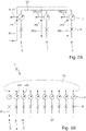
- FIG 4 another bottling plant 1 is shown schematically. As an alternative to the method described above, this performs a calibration via a separate flow calibration device 18 . This implements regulation and is in communication with the flow measuring devices 7 in the respective filling elements, which are arranged in the ring line 10, in order to increase knowledge of the measurement deviation as a function of the respectively measured flow values.
- the above disclosure is - insofar as technically meaningful - fully applicable to this embodiment.
- FIG 5 another bottling plant 1 is shown schematically. This has 10 different interrupters 19 in its loop. These are each arranged after two filling elements in order to interrupt further flow of the filling product in the ring line 10 .
- bridging lines 20 are provided, which provide a connection between the filling product outlets of two adjacent filling elements and thus bridge the respective interrupters 19 . In this way, communication between the individual filling elements can be made possible despite the interrupters 19.
Landscapes
- Chemical & Material Sciences (AREA)
- Chemical Kinetics & Catalysis (AREA)
- Physics & Mathematics (AREA)
- Fluid Mechanics (AREA)
- Filling Of Jars Or Cans And Processes For Cleaning And Sealing Jars (AREA)
- Basic Packing Technique (AREA)
Applications Claiming Priority (1)
| Application Number | Priority Date | Filing Date | Title |
|---|---|---|---|
| DE102020130738.1A DE102020130738A1 (de) | 2020-11-20 | 2020-11-20 | Verfahren zum Kalibrieren eines Füllorgans in einer Abfüllanlage |
Publications (1)
| Publication Number | Publication Date |
|---|---|
| EP4001207A1 true EP4001207A1 (fr) | 2022-05-25 |
Family
ID=78824823
Family Applications (1)
| Application Number | Title | Priority Date | Filing Date |
|---|---|---|---|
| EP21209177.1A Pending EP4001207A1 (fr) | 2020-11-20 | 2021-11-19 | Procédé d'étalonnage d'un organe de remplissage dans une installation de remplissage |
Country Status (3)
| Country | Link |
|---|---|
| EP (1) | EP4001207A1 (fr) |
| CN (1) | CN114516609B (fr) |
| DE (1) | DE102020130738A1 (fr) |
Families Citing this family (4)
| Publication number | Priority date | Publication date | Assignee | Title |
|---|---|---|---|---|
| DE102022122713A1 (de) * | 2022-09-07 | 2024-03-07 | Krones Aktiengesellschaft | Füllsystem und Verfahren zum Überwachen eines Füllsystems |
| DE102022124947A1 (de) | 2022-09-28 | 2024-03-28 | Krohne Messtechnik Gmbh | Verfahren zum Kalibrieren einer Abfüllanlage und Abfüllanlage |
| DE102022128366A1 (de) | 2022-10-26 | 2024-05-02 | Endress+Hauser Flowtec Ag | Verfahren zum Justieren und/oder Kalibrieren eines Durchflussmessgerätes und Durchflussmessgerät |
| DE102024001651A1 (de) * | 2024-05-22 | 2025-11-27 | Krohne Messtechnik Gmbh | Verfahren zum Betreiben einer Abfüllanlage und Abfüllanlage |
Citations (8)
| Publication number | Priority date | Publication date | Assignee | Title |
|---|---|---|---|---|
| DE102006062536A1 (de) | 2006-12-29 | 2008-07-03 | Krones Ag | Vorrichtung und Verfahren zum Befüllen von Behältnissen |
| EP2460761A1 (fr) * | 2010-12-03 | 2012-06-06 | Krones AG | Dispositif et procédé destinés au remplissage de récipients |
| US8985161B2 (en) * | 2006-06-27 | 2015-03-24 | Khs Gmbh | Method of operating a beverage bottling or container filling arrangement with a filling volume correcting apparatus |
| DE102014107364A1 (de) * | 2014-05-26 | 2015-11-26 | Endress+Hauser Process Solutions Ag | Verfahren zum ventilgesteuerten Abfüllen |
| EP2881361B1 (fr) * | 2013-12-06 | 2016-09-07 | Krones AG | Organe de remplissage destiné au remplissage d'un produit de remplissage dans un récipient et procédé de nettoyage de l'organe de remplissage |
| EP3078627A1 (fr) | 2015-04-08 | 2016-10-12 | Sidel Participations, S.A.S. | Procédé et système de remplissage pour un récipient avec un produit liquide et machine de remplissage correspondante |
| EP3553022A1 (fr) * | 2018-04-13 | 2019-10-16 | Sacmi Beverage S.p.A. | Machine de remplissage |
| DE102016106210B4 (de) * | 2016-04-05 | 2020-09-03 | Krones Aktiengesellschaft | Vorrichtung und Verfahren zum Befüllen eines Behälters mit einem Füllprodukt |
Family Cites Families (3)
| Publication number | Priority date | Publication date | Assignee | Title |
|---|---|---|---|---|
| FR2899220B1 (fr) * | 2006-03-31 | 2008-05-30 | Sidel Participations | Dispositif de nettoyage pour machine de remplissage |
| IT1395607B1 (it) * | 2009-09-14 | 2012-10-16 | Ft System Srl | Impianto di riempimento di bottiglie o contenitori a taratura continua e metodo di taratura in continuo di un tale impianto |
| CN111908405B (zh) * | 2020-06-19 | 2025-06-20 | 北京航天斯达科技有限公司 | 一种带有反馈补偿方式的灌装系统及灌装方法 |
-
2020
- 2020-11-20 DE DE102020130738.1A patent/DE102020130738A1/de active Pending
-
2021
- 2021-11-18 CN CN202111368197.0A patent/CN114516609B/zh active Active
- 2021-11-19 EP EP21209177.1A patent/EP4001207A1/fr active Pending
Patent Citations (8)
| Publication number | Priority date | Publication date | Assignee | Title |
|---|---|---|---|---|
| US8985161B2 (en) * | 2006-06-27 | 2015-03-24 | Khs Gmbh | Method of operating a beverage bottling or container filling arrangement with a filling volume correcting apparatus |
| DE102006062536A1 (de) | 2006-12-29 | 2008-07-03 | Krones Ag | Vorrichtung und Verfahren zum Befüllen von Behältnissen |
| EP2460761A1 (fr) * | 2010-12-03 | 2012-06-06 | Krones AG | Dispositif et procédé destinés au remplissage de récipients |
| EP2881361B1 (fr) * | 2013-12-06 | 2016-09-07 | Krones AG | Organe de remplissage destiné au remplissage d'un produit de remplissage dans un récipient et procédé de nettoyage de l'organe de remplissage |
| DE102014107364A1 (de) * | 2014-05-26 | 2015-11-26 | Endress+Hauser Process Solutions Ag | Verfahren zum ventilgesteuerten Abfüllen |
| EP3078627A1 (fr) | 2015-04-08 | 2016-10-12 | Sidel Participations, S.A.S. | Procédé et système de remplissage pour un récipient avec un produit liquide et machine de remplissage correspondante |
| DE102016106210B4 (de) * | 2016-04-05 | 2020-09-03 | Krones Aktiengesellschaft | Vorrichtung und Verfahren zum Befüllen eines Behälters mit einem Füllprodukt |
| EP3553022A1 (fr) * | 2018-04-13 | 2019-10-16 | Sacmi Beverage S.p.A. | Machine de remplissage |
Also Published As
| Publication number | Publication date |
|---|---|
| CN114516609B (zh) | 2024-09-24 |
| CN114516609A (zh) | 2022-05-20 |
| DE102020130738A1 (de) | 2022-05-25 |
Similar Documents
| Publication | Publication Date | Title |
|---|---|---|
| EP4001207A1 (fr) | Procédé d'étalonnage d'un organe de remplissage dans une installation de remplissage | |
| DE102007030559B4 (de) | Verfahren zum Füllen von Flaschen oder dergleichen Behältern sowie Füllsystem | |
| EP2272790B1 (fr) | Dispositif et procédé de remplissage de boissons à plusieurs composants | |
| EP2708491B1 (fr) | Dispositif et procédé de remplissage d'un récipient avec un produit de remplissage | |
| EP2272791B1 (fr) | Dispositif de remplissage de récipients à l'aide de liquides à plusieurs composants | |
| DE4117287A1 (de) | Verfahren zum fuellen von flaschen, dosen o. dgl. behaelter sowie fuellmaschine zum durchfuehren dieses verfahrens | |
| EP0347607A2 (fr) | Procédé et dispositif pour amener un produit à pulvériser à une pluralité de postes de pulvérisation | |
| EP1165245A1 (fr) | Procede et dispositif de remplissage d'un reservoir pressurise avec un fluide | |
| EP2459335A1 (fr) | Dispositif et procédé de refroidissement secondaire commandé d'une installation de coulée continue | |
| EP4005971A1 (fr) | Dispositif et procédé de remplissage d'un récipient d'un produit de remplissage | |
| EP3498659B1 (fr) | Procédé et dispositif de remplissage d'un produit de remplissage | |
| DE4302165C1 (de) | Verfahren und Anlage zur Regulierung des Fettgehaltes von Milch und Rahm | |
| DE102004049655A1 (de) | Verfahren und Vorrichtung zur Dichtheitsprüfung der Hauptluftleitung von Eisenbahnfahrzeugen | |
| EP3672903B1 (fr) | Procédé pour remplir des récipients avec des produits | |
| EP2361696B1 (fr) | Installation de remplissage pour le remplissage de récipients et son procédé de fonctionnement | |
| DE2410735C3 (de) | Vorrichtung zur Regelung der Stärke der aus einer Öffnung eines Gefäßes durch ein gesteuert verschiebbares Absperrventil in eine Stranggießkokille zu vergießenden Metallschmelze | |
| DE10152234A1 (de) | Vorrichtung zum Dosieren einer Flüssigkeit in Behälter | |
| EP3683185B1 (fr) | Dispositif et procédé de remplissage d'un récipient avec un produit de remplissage | |
| EP4345427B1 (fr) | Procédé d'étalonnage d'une installation de remplissage et installation de remplissage | |
| DE102006031969B4 (de) | Verfahren zum Steuern einer Durchflussmesseinrichtung und Vorrichtung zum Dosieren von Flüssigkeiten | |
| EP1567837B1 (fr) | Procede de regulation de quantites de complement de niveau dans des installations de soutirage | |
| EP1570241A1 (fr) | Procede pour transvaser une quantite definie d'un milieu dans un recipient | |
| DE10154352B4 (de) | Dosiervorrichtung zum Dosieren eines strömenden Mediums | |
| DE102016103786A1 (de) | Verfahren zur geregelten und/oder gesteuerten Abgabe eines Abfüllmediums an eine Behältniseinheit und Abfüllmaschine | |
| EP1764159B1 (fr) | Dispositif et procédé de revêtement |
Legal Events
| Date | Code | Title | Description |
|---|---|---|---|
| PUAI | Public reference made under article 153(3) epc to a published international application that has entered the european phase |
Free format text: ORIGINAL CODE: 0009012 |
|
| STAA | Information on the status of an ep patent application or granted ep patent |
Free format text: STATUS: THE APPLICATION HAS BEEN PUBLISHED |
|
| AK | Designated contracting states |
Kind code of ref document: A1 Designated state(s): AL AT BE BG CH CY CZ DE DK EE ES FI FR GB GR HR HU IE IS IT LI LT LU LV MC MK MT NL NO PL PT RO RS SE SI SK SM TR |
|
| STAA | Information on the status of an ep patent application or granted ep patent |
Free format text: STATUS: REQUEST FOR EXAMINATION WAS MADE |
|
| 17P | Request for examination filed |
Effective date: 20221028 |
|
| RBV | Designated contracting states (corrected) |
Designated state(s): AL AT BE BG CH CY CZ DE DK EE ES FI FR GB GR HR HU IE IS IT LI LT LU LV MC MK MT NL NO PL PT RO RS SE SI SK SM TR |
|
| P01 | Opt-out of the competence of the unified patent court (upc) registered |
Effective date: 20230523 |
|
| STAA | Information on the status of an ep patent application or granted ep patent |
Free format text: STATUS: EXAMINATION IS IN PROGRESS |