EP4001221A1 - Vorrichtung zur chlorherstellung durch elektrochlorierung - Google Patents
Vorrichtung zur chlorherstellung durch elektrochlorierung Download PDFInfo
- Publication number
- EP4001221A1 EP4001221A1 EP21208560.9A EP21208560A EP4001221A1 EP 4001221 A1 EP4001221 A1 EP 4001221A1 EP 21208560 A EP21208560 A EP 21208560A EP 4001221 A1 EP4001221 A1 EP 4001221A1
- Authority
- EP
- European Patent Office
- Prior art keywords
- tank
- solution
- electrochlorination
- wall
- thermodynamic
- Prior art date
- Legal status (The legal status is an assumption and is not a legal conclusion. Google has not performed a legal analysis and makes no representation as to the accuracy of the status listed.)
- Withdrawn
Links
- 239000000460 chlorine Substances 0.000 title claims abstract description 35
- ZAMOUSCENKQFHK-UHFFFAOYSA-N Chlorine atom Chemical compound [Cl] ZAMOUSCENKQFHK-UHFFFAOYSA-N 0.000 title claims abstract description 31
- 229910052801 chlorine Inorganic materials 0.000 title claims abstract description 30
- 230000033228 biological regulation Effects 0.000 claims abstract description 16
- 150000001805 chlorine compounds Chemical class 0.000 claims abstract description 3
- 239000000243 solution Substances 0.000 claims description 88
- 238000005868 electrolysis reaction Methods 0.000 claims description 39
- 238000004519 manufacturing process Methods 0.000 claims description 29
- 238000009413 insulation Methods 0.000 claims description 16
- XTEGARKTQYYJKE-UHFFFAOYSA-M Chlorate Chemical class [O-]Cl(=O)=O XTEGARKTQYYJKE-UHFFFAOYSA-M 0.000 claims description 11
- 239000000463 material Substances 0.000 claims description 11
- 239000004033 plastic Substances 0.000 claims description 9
- 238000009826 distribution Methods 0.000 claims description 8
- 230000000694 effects Effects 0.000 claims description 4
- 239000012266 salt solution Substances 0.000 claims description 4
- 239000004794 expanded polystyrene Substances 0.000 claims description 3
- 239000011491 glass wool Substances 0.000 claims description 3
- 239000011490 mineral wool Substances 0.000 claims description 3
- 210000002268 wool Anatomy 0.000 claims description 3
- 238000001816 cooling Methods 0.000 abstract description 7
- 238000000034 method Methods 0.000 description 13
- 150000003839 salts Chemical class 0.000 description 12
- XLYOFNOQVPJJNP-UHFFFAOYSA-N water Substances O XLYOFNOQVPJJNP-UHFFFAOYSA-N 0.000 description 11
- FAPWRFPIFSIZLT-UHFFFAOYSA-M Sodium chloride Chemical compound [Na+].[Cl-] FAPWRFPIFSIZLT-UHFFFAOYSA-M 0.000 description 10
- 230000008569 process Effects 0.000 description 10
- 238000006243 chemical reaction Methods 0.000 description 8
- WQYVRQLZKVEZGA-UHFFFAOYSA-N hypochlorite Chemical compound Cl[O-] WQYVRQLZKVEZGA-UHFFFAOYSA-N 0.000 description 8
- 230000005611 electricity Effects 0.000 description 5
- 239000011810 insulating material Substances 0.000 description 5
- 239000011780 sodium chloride Substances 0.000 description 5
- 239000005708 Sodium hypochlorite Substances 0.000 description 4
- 230000008901 benefit Effects 0.000 description 4
- 239000003651 drinking water Substances 0.000 description 4
- 235000020188 drinking water Nutrition 0.000 description 4
- 239000007789 gas Substances 0.000 description 4
- SUKJFIGYRHOWBL-UHFFFAOYSA-N sodium hypochlorite Chemical compound [Na+].Cl[O-] SUKJFIGYRHOWBL-UHFFFAOYSA-N 0.000 description 4
- PPKPKFIWDXDAGC-IHWYPQMZSA-N (z)-1,2-dichloroprop-1-ene Chemical compound C\C(Cl)=C\Cl PPKPKFIWDXDAGC-IHWYPQMZSA-N 0.000 description 3
- 239000013626 chemical specie Substances 0.000 description 3
- 239000012212 insulator Substances 0.000 description 3
- 238000005259 measurement Methods 0.000 description 3
- 238000002156 mixing Methods 0.000 description 3
- XKRFYHLGVUSROY-UHFFFAOYSA-N Argon Chemical compound [Ar] XKRFYHLGVUSROY-UHFFFAOYSA-N 0.000 description 2
- VEXZGXHMUGYJMC-UHFFFAOYSA-M Chloride anion Chemical compound [Cl-] VEXZGXHMUGYJMC-UHFFFAOYSA-M 0.000 description 2
- UFHFLCQGNIYNRP-UHFFFAOYSA-N Hydrogen Chemical compound [H][H] UFHFLCQGNIYNRP-UHFFFAOYSA-N 0.000 description 2
- WCUXLLCKKVVCTQ-UHFFFAOYSA-M Potassium chloride Chemical compound [Cl-].[K+] WCUXLLCKKVVCTQ-UHFFFAOYSA-M 0.000 description 2
- 239000002253 acid Substances 0.000 description 2
- 238000010586 diagram Methods 0.000 description 2
- 239000011521 glass Substances 0.000 description 2
- 230000036541 health Effects 0.000 description 2
- 230000017525 heat dissipation Effects 0.000 description 2
- 239000007788 liquid Substances 0.000 description 2
- 230000004224 protection Effects 0.000 description 2
- 238000007493 shaping process Methods 0.000 description 2
- OYPRJOBELJOOCE-UHFFFAOYSA-N Calcium Chemical compound [Ca] OYPRJOBELJOOCE-UHFFFAOYSA-N 0.000 description 1
- 229920000742 Cotton Polymers 0.000 description 1
- 241000195493 Cryptophyta Species 0.000 description 1
- FYYHWMGAXLPEAU-UHFFFAOYSA-N Magnesium Chemical compound [Mg] FYYHWMGAXLPEAU-UHFFFAOYSA-N 0.000 description 1
- 241000237852 Mollusca Species 0.000 description 1
- 230000005679 Peltier effect Effects 0.000 description 1
- 239000004743 Polypropylene Substances 0.000 description 1
- 241001639412 Verres Species 0.000 description 1
- 230000003213 activating effect Effects 0.000 description 1
- 229910052786 argon Inorganic materials 0.000 description 1
- 230000008033 biological extinction Effects 0.000 description 1
- 238000009529 body temperature measurement Methods 0.000 description 1
- 239000001110 calcium chloride Substances 0.000 description 1
- 229910001628 calcium chloride Inorganic materials 0.000 description 1
- 239000003990 capacitor Substances 0.000 description 1
- 239000002131 composite material Substances 0.000 description 1
- 230000008602 contraction Effects 0.000 description 1
- 239000007799 cork Substances 0.000 description 1
- 230000001419 dependent effect Effects 0.000 description 1
- 238000013461 design Methods 0.000 description 1
- 238000001514 detection method Methods 0.000 description 1
- 238000011982 device technology Methods 0.000 description 1
- 230000005684 electric field Effects 0.000 description 1
- 239000000839 emulsion Substances 0.000 description 1
- 238000005516 engineering process Methods 0.000 description 1
- 238000011156 evaluation Methods 0.000 description 1
- 238000000605 extraction Methods 0.000 description 1
- 239000000835 fiber Substances 0.000 description 1
- 239000011152 fibreglass Substances 0.000 description 1
- 238000011049 filling Methods 0.000 description 1
- 238000000265 homogenisation Methods 0.000 description 1
- 238000011065 in-situ storage Methods 0.000 description 1
- 230000003993 interaction Effects 0.000 description 1
- 229910052743 krypton Inorganic materials 0.000 description 1
- DNNSSWSSYDEUBZ-UHFFFAOYSA-N krypton atom Chemical compound [Kr] DNNSSWSSYDEUBZ-UHFFFAOYSA-N 0.000 description 1
- WABPQHHGFIMREM-UHFFFAOYSA-N lead(0) Chemical compound [Pb] WABPQHHGFIMREM-UHFFFAOYSA-N 0.000 description 1
- 239000004973 liquid crystal related substance Substances 0.000 description 1
- TWRXJAOTZQYOKJ-UHFFFAOYSA-L magnesium chloride Substances [Mg+2].[Cl-].[Cl-] TWRXJAOTZQYOKJ-UHFFFAOYSA-L 0.000 description 1
- 229910001629 magnesium chloride Inorganic materials 0.000 description 1
- 239000000203 mixture Substances 0.000 description 1
- 238000013021 overheating Methods 0.000 description 1
- 125000005498 phthalate group Chemical class 0.000 description 1
- 231100000614 poison Toxicity 0.000 description 1
- 230000007096 poisonous effect Effects 0.000 description 1
- -1 polypropylene Polymers 0.000 description 1
- 229920001155 polypropylene Polymers 0.000 description 1
- 239000001103 potassium chloride Substances 0.000 description 1
- 235000011164 potassium chloride Nutrition 0.000 description 1
- 230000035755 proliferation Effects 0.000 description 1
- 230000001737 promoting effect Effects 0.000 description 1
- 239000011253 protective coating Substances 0.000 description 1
- 230000001681 protective effect Effects 0.000 description 1
- 230000035484 reaction time Effects 0.000 description 1
- 238000011084 recovery Methods 0.000 description 1
- 238000005057 refrigeration Methods 0.000 description 1
- 230000002441 reversible effect Effects 0.000 description 1
- 230000035939 shock Effects 0.000 description 1
- 238000004659 sterilization and disinfection Methods 0.000 description 1
- 238000003756 stirring Methods 0.000 description 1
- 239000000126 substance Substances 0.000 description 1
- 239000012209 synthetic fiber Substances 0.000 description 1
- 229920002994 synthetic fiber Polymers 0.000 description 1
- 238000004448 titration Methods 0.000 description 1
- 229910052724 xenon Inorganic materials 0.000 description 1
- FHNFHKCVQCLJFQ-UHFFFAOYSA-N xenon atom Chemical compound [Xe] FHNFHKCVQCLJFQ-UHFFFAOYSA-N 0.000 description 1
Images


Classifications
-
- C—CHEMISTRY; METALLURGY
- C02—TREATMENT OF WATER, WASTE WATER, SEWAGE, OR SLUDGE
- C02F—TREATMENT OF WATER, WASTE WATER, SEWAGE, OR SLUDGE
- C02F1/00—Treatment of water, waste water, or sewage
- C02F1/46—Treatment of water, waste water, or sewage by electrochemical methods
- C02F1/461—Treatment of water, waste water, or sewage by electrochemical methods by electrolysis
- C02F1/467—Treatment of water, waste water, or sewage by electrochemical methods by electrolysis by electrochemical disinfection; by electrooxydation or by electroreduction
- C02F1/4672—Treatment of water, waste water, or sewage by electrochemical methods by electrolysis by electrochemical disinfection; by electrooxydation or by electroreduction by electrooxydation
- C02F1/4674—Treatment of water, waste water, or sewage by electrochemical methods by electrolysis by electrochemical disinfection; by electrooxydation or by electroreduction by electrooxydation with halogen or compound of halogens, e.g. chlorine, bromine
-
- C—CHEMISTRY; METALLURGY
- C02—TREATMENT OF WATER, WASTE WATER, SEWAGE, OR SLUDGE
- C02F—TREATMENT OF WATER, WASTE WATER, SEWAGE, OR SLUDGE
- C02F2201/00—Apparatus for treatment of water, waste water or sewage
- C02F2201/008—Mobile apparatus and plants, e.g. mounted on a vehicle
-
- C—CHEMISTRY; METALLURGY
- C02—TREATMENT OF WATER, WASTE WATER, SEWAGE, OR SLUDGE
- C02F—TREATMENT OF WATER, WASTE WATER, SEWAGE, OR SLUDGE
- C02F2201/00—Apparatus for treatment of water, waste water or sewage
- C02F2201/46—Apparatus for electrochemical processes
- C02F2201/461—Electrolysis apparatus
- C02F2201/46105—Details relating to the electrolytic devices
- C02F2201/46155—Heating or cooling
-
- C—CHEMISTRY; METALLURGY
- C02—TREATMENT OF WATER, WASTE WATER, SEWAGE, OR SLUDGE
- C02F—TREATMENT OF WATER, WASTE WATER, SEWAGE, OR SLUDGE
- C02F2201/00—Apparatus for treatment of water, waste water or sewage
- C02F2201/46—Apparatus for electrochemical processes
- C02F2201/461—Electrolysis apparatus
- C02F2201/46105—Details relating to the electrolytic devices
- C02F2201/4616—Power supply
- C02F2201/46165—Special power supply, e.g. solar energy or batteries
-
- C—CHEMISTRY; METALLURGY
- C02—TREATMENT OF WATER, WASTE WATER, SEWAGE, OR SLUDGE
- C02F—TREATMENT OF WATER, WASTE WATER, SEWAGE, OR SLUDGE
- C02F2209/00—Controlling or monitoring parameters in water treatment
- C02F2209/02—Temperature
-
- C—CHEMISTRY; METALLURGY
- C02—TREATMENT OF WATER, WASTE WATER, SEWAGE, OR SLUDGE
- C02F—TREATMENT OF WATER, WASTE WATER, SEWAGE, OR SLUDGE
- C02F2303/00—Specific treatment goals
- C02F2303/04—Disinfection
-
- Y—GENERAL TAGGING OF NEW TECHNOLOGICAL DEVELOPMENTS; GENERAL TAGGING OF CROSS-SECTIONAL TECHNOLOGIES SPANNING OVER SEVERAL SECTIONS OF THE IPC; TECHNICAL SUBJECTS COVERED BY FORMER USPC CROSS-REFERENCE ART COLLECTIONS [XRACs] AND DIGESTS
- Y02—TECHNOLOGIES OR APPLICATIONS FOR MITIGATION OR ADAPTATION AGAINST CLIMATE CHANGE
- Y02W—CLIMATE CHANGE MITIGATION TECHNOLOGIES RELATED TO WASTEWATER TREATMENT OR WASTE MANAGEMENT
- Y02W10/00—Technologies for wastewater treatment
- Y02W10/30—Wastewater or sewage treatment systems using renewable energies
- Y02W10/37—Wastewater or sewage treatment systems using renewable energies using solar energy
Definitions
- the present invention relates to a device intended to produce active chlorine (sodium hypochlorite) by electrochlorination.
- Electrochlorination thus consists of using electrodes immersed in a salt solution to allow the production of chlorine.
- electrochlorination is a technique which generally allows the in situ production of a solution enriched in sodium hypochlorite from a solution containing sodium chloride (kitchen salt also more simply referred to as "salt”) .
- This process is used for the production of a disinfection solution for water.
- the known applications of this process are numerous. They can be industrial, such as water treatment or the fight against the proliferation of algae or molluscs.
- Another application of this process concerns the potabilisation of water. This is an important application when drinking water is not or no longer accessible to populations, for example in an area that has experienced a natural disaster, drought, in a war zone, etc.
- the present invention thus relates more particularly to a device for making water drinkable.
- drinking water should not contain more than 0.2 to 0.7 mg/L of chlorates, according to certain world reference organizations, in particular the WHO.
- FR2976573 discloses a process for the production of chlorine by electrochlorination using electrodes immersed in a solution containing salt (sodium chloride, also called “kitchen salt”). FR2976573 considers in particular the use of water sea. According to the teaching of this document, the electrodes are supplied by means of photovoltaic electricity production over the course of sunshine, and the process of chlorine production is controlled, and in particular the supply or not of the electrodes and the voltage level applied, using control means supplied with electricity by said means for producing electricity.
- salt sodium chloride
- the document GB2202551 presents a device for preparing sodium hypochlorite in a tank which is thermally insulated by an insulating material.
- the tank is surrounded by a cooling tube, linked to a compressor and a condenser.
- the objective of this document is to greatly increase the concentration of hypochlorite (typically up to 40g/L in 12 hours) in the solution formed by controlling the temperature using a powerful means of refrigeration.
- the present invention aims to provide an electrochlorination device which solves at least one of the problems set out above.
- the present invention relates to a device for producing chlorine by electrochlorination of a solution containing chlorides.
- the device comprises a tank forming an interior volume intended to receive said solution and an electrolyser installed in the tank.
- the device comprises an enclosure in which the tank is arranged or formed, said enclosure being configured so as to thermally insulate the interior volume of the tank from the ambient atmosphere outside the device.
- the device further comprises a thermal regulation device comprising a thermodynamic device suitable for cooling the solution present in the tank. More particularly, the thermodynamic device comprises a Peltier module.
- the thermodynamic device is installed at the bottom of the tank of the device for producing chlorine by electrochlorination.
- known electrochlorination devices comprise a tank which has no particular thermal property, or which is as thermally conductive as possible to promote cooling. of the solution through the walls of the tank.
- the present device allows fine and permanent control and piloting of the temperature of the electrolyzed solution.
- the temperature control carried out thus mainly makes it possible to avoid producing substances that are harmful to health and to optimize the production time, compared to known analogous systems, and not to promote a significant increase in the concentration of hypochlorite.
- Peltier module is particularly advantageous. It allows the generation of cold thanks to a moderate electric current. It is a compact and reliable device. The operation of a Peltier module is also very easy to control.
- thermodynamic device makes it possible to amplify a flow generated by electrolysis in the solution contained in the tank, which allows it to be mixed.
- the tank may comprise an electrolysis column comprising the electrolyser, said electrolysis column being installed in the interior volume and being oriented so as to extend substantially vertically when the device is used, the tank being configured so that a solution present in the tank can flow in said electrolysis column from one end to another of said electrolysis column.
- the device may also include a section restriction adapted to accelerate a flow of solution flowing from the bottom of the electrolysis column to the top of the latter and to generate a Venturi effect in said flow.
- the configuration, and in particular the ratio between the height and the surface of the cross section of the electrolysis column thus favors the upward flow of solution in the electrolysis column thanks to the production of dihydrogen at the level of the electrodes of the electrolyser.
- the implementation of a section restriction causing a venturi effect accelerates the flow of solution in the column and also promotes mixing and homogenization of the solution in the tank.
- the device may also include a heat sink, preferably of the cooler type, which is configured to dissipate the heat extracted from the solution by the thermodynamic device.
- a heat sink allows effective evacuation of the calories taken from the solution by the thermodynamic device (typically by the Peltier module).
- a cooler-type heat sink proves to be particularly suitable in that it is simple efficient and only requires an electrical power supply to operate.
- the enclosure of the device may comprise an outer wall and an inner wall, said inner wall forming a volume adapted to receive the tank or forming said tank, the inner wall and the outer wall being spaced apart so as to form an insulation layer therebetween.
- a double wall proves to be a particularly well-suited configuration for ensuring the thermal insulation of the interior volume of the tank.
- This thermal insulation can use various known insulating materials, some of which are mentioned above by way of example.
- the device may include electronic means suitable for automatically detecting the type of electrical power supply.
- the device is advantageously configured to be able to be powered electrically by each of the aforementioned power supplies. In certain embodiments, it can be connected to several of these sources of electrical energy simultaneously.
- the device can thus adapt to the electricity sources available where it is implemented.
- the solar power supply allows total autonomy of the device.
- the use of a battery as the main power source is also possible, for example in cases where photovoltaic panels are not available and it is not possible to use an electrical network or a generator.
- the photovoltaic power supply can also, in certain embodiments, be used to recharge a battery that can take over from the photovoltaic power supply when the sunshine is not sufficient.
- food electricity by an electrical distribution network, or by a generator is also possible.
- a device combining these three power supply possibilities can be adapted to many employment situations.
- the device may include a system for assisting the positioning of the photovoltaic panels to maximize the electrical energy, when the electrical power supply includes a set of photovoltaic panels.
- the device may also comprise an electronic control device.
- This device is suitable for controlling the operation of the electrolyser and of the thermodynamic device according to at least one parameter, in order to limit the chlorine production time while limiting or preventing the production of chlorates.
- control of the various parameters of the electrochlorination reaction in particular the temperature of the solution and its concentration in salt (typically in sodium chloride) or in active chlorine, and the control of the parameters of the device allowing to play on the reaction of electrochlorination (in particular the power of the thermodynamic device and/or the voltage applied to the electrodes of the electrolyser), make it possible to control the electrochlorination reaction in order to optimize it.
- the evaluation of the chlorine content (or corollary of the salt content) in the solution can be carried out without direct measurement. Indeed, by knowing the initial salt concentration of the electrolyzed solution, and by measuring the electrical charge passed through the device during its use, the amount of chlorine produced can be evaluated.
- the internal volume of the tank of the device can be comprised, by way of example, between 1 L and 10 L. It may for example be of the order of 5L.
- a device having such a capacity is easily transportable. It nevertheless makes it possible to meet the needs for the production of drinking water in many situations.
- the present invention therefore aims at a transportable system, and not an industrial system.
- the device may comprise a man-machine interface comprising status indicators, such as one or more light-emitting diodes, a buzzer, loudspeaker or buzzer, a screen, and one or more control buttons, and preferably a single control button.
- status indicators such as one or more light-emitting diodes, a buzzer, loudspeaker or buzzer, a screen, and one or more control buttons, and preferably a single control button.
- the device that is the subject of the present invention is advantageously very easy to use.
- a single button for activating that is to say putting into production), optionally deactivating, choosing an operating mode if necessary, and reinitializing the device, may thus be sufficient to control it effectively.
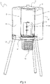
- the figure 1 represents, according to a schematic three-dimensional view, a device according to one embodiment of the invention.
- the electrochlorination device in accordance with the invention comprises a tank 1 which defines an interior volume 2.
- the tank 1 is formed of a material resistant to chemical species present, or the inner wall of the tank is covered with such a material.
- the tank 1 can thus be made of plastic material (including composite, for example based on fiberglass) or of glass. It may be metallic, if necessary being covered, on its inner wall, with a material resistant to the chemical species present, for example a suitable plastic material.
- the parts of tank 1, and more generally of the electrochlorination device, which come into contact with the electrolyzed solution are advantageously made of a material suitable for food contact.
- the use of materials that are unlikely to release phthalates into the solution is preferred.
- the tank 1 of an electrochlorination device in accordance with the invention has the particularity of being thermally insulated 2 with respect to the ambient atmosphere 3 which prevails around the electrochlorination device.
- thermally insulated is meant to significantly reduce the heat exchanges between the interior volume of the vessel and the ambient atmosphere 3 outside.
- the thermal resistance of the walls of the tank and of the enclosure of the embodiment described here by way of example can be of the order of 3 KW -1
- the thermal resistance of the device that is the subject of the invention can therefore be 150 to 330 times higher than that of a device comprising a conventional plastic tank.
- the tank 1 is placed, in the example shown here, in an insulating enclosure 6.
- the enclosure 6 comprises an outer wall 4 and an inner wall 5.
- the inner wall 5 defines a volume shaped to receive the tank 1.
- the volume defined by the inner wall 5 of the enclosure 6 can correspond, to a functional clearance close to the outer shape of tank 1.
- the enclosure 6 and the tank 1 are represented in transparency on the figure 1 .
- the inner wall 5 and the outer wall 4 are spaced apart.
- the distance between said inner wall 5 and outer wall 4 may be substantially equal at all points of said walls.
- the outer wall 4, which defines the outer shape of a part of the device can have a generally cylindrical shape, and the inner wall 5 can define a reception volume of the tank 1 itself cylindrical, of smaller diameter and arranged coaxially with respect to the cylinder defined by the outer wall 4.
- a space is thus defined between the inner wall 5 and the outer wall 4. This space forms an insulation layer 6.
- the insulation layer thus formed may simply be an air layer. This layer of air may be at atmospheric pressure, or at reduced pressure to improve the thermal insulation characteristics.
- the vacuum can thus be created between the inner wall 5 and the outer wall 4 of the tank.
- vacuum is meant air at a reduced pressure or even almost zero.
- the insulating layer may be filled in whole or in part with an insulating material.
- the insulation layer can be filled with an insulating gas (argon, krypton, xenon, etc.).
- the insulation layer can be filled with an insulating liquid.
- the insulation layer can be filled with an expanded plastic material such as expanded polystyrene or expanded polypropylene.
- Other insulating materials can be used successfully to fill the insulation layer.
- natural insulators such as cork can be used.
- Fibrous insulators can be used such as insulators based on natural fibers, for example wool or cotton, or based on synthetic fibers such as glass wool or rock wool.
- Insulating materials having a low thermal conductivity for example less than 0.1 W m -1 K -1 are advantageously used.
- the enclosure and the tank can form a single element.
- the interior wall 4 of the enclosure forms the tank 1 and defines the interior volume 2.
- the device comprises an electrolyser 7 inside the tank 1.
- the electrolyser 7 is a system comprising at least two electrodes to which an electric voltage is imposed so as to carry out the electrolysis of a solution comprising salt previously introduced into tank.
- the electrolyser used in a preferred embodiment of the invention comprises four electrodes, and an electric voltage is imposed between the two most distant electrodes, so that the two intermediate electrodes are not supplied directly.
- the electrolysis of the salt solution contained in the tank makes it possible to produce active chlorine in said tank.
- the tank is closed in its upper part by a lid 8.
- the removal of the lid 8 allows the filling of the tank with the solution to be electrolyzed as well as, if necessary, the recovery of the chlorine solution obtained after electrolysis.
- the tank 1 can be equipped with a tap in the lower part, allowing the tank to be emptied.
- the device comprises a thermal regulation device.
- the thermal regulation device generally makes it possible to control and control the temperature of the solution present in the tank. It thus comprises, in the example shown, a thermodynamic device 9, a temperature sensor, and regulation means, for example an electronic control device, controlling the operation of the thermodynamic device 9 and, where appropriate, of the electrolyser 7.
- thermodynamic device 9 makes it possible in particular to cool the solution present in the tank 1.
- the thermodynamic device 9 therefore allows the extraction of calories from the solution present in the tank towards the outside atmosphere.
- thermodynamic device 9 therefore constitutes a cooler, and, optionally, a heater.
- thermodynamic device technologies can be envisaged.
- the use of a Peltier effect module (or "Peltier module") is preferred.
- a Peltier module or thermoelectric cooler, allows the generation of cold from an electric current.
- the cold part of the Peltier module is positioned in the tank or in contact with a conductive wall of tank 1.
- the Peltier module (or other suitable thermodynamic device, which can be designated by the name "cold group”) is thus configured and arranged so as to drain a certain thermal power from the interior volume of the tank to the outside of the device. .
- This allows thermal regulation of the solution present in the tank.
- the cooling obtained thanks to the Peltier module makes it possible to maintain the solution present in the tank at a temperature at which electrochlorination does not cause a significant generation of chlorate (typically below 40°C).
- the thermal regulation device further comprises a temperature sensor 10 present in the tank, and associated automatic regulation means, which allow the control of the thermal regulation of the solution present in the tank.
- the control of the Peltier module makes it possible to regulate the temperature of the solution present in the tank 1 for produce the chlorine solution as quickly as possible.
- the principle developed in the invention thus resides in the counterintuitive combination, compared to the devices known in the state of the art, of a thermally insulating enclosure 6 which prevents the natural dissipation of the heat from the solution present in the tank 1 towards the outside atmosphere (while electrolysis tends to increase this temperature) and a thermal regulation device comprising a thermodynamic device making it possible to extract heat from the solution present in the tank (preferably a Peltier module) , the control of which allows regulation of the temperature of the electrolyzed solution.
- the device also comprises a heat sink.
- the heat sink 11 is configured to dissipate the calories drained from inside the tank 1 into the atmosphere outside the device.
- the heat sink 11 can be placed under the tank 1 near or even in contact with the thermodynamic device 9.
- the heat sink 11 is advantageously of the ventirad type.
- a “ventirad” which is the contraction of the words fan and radiator designates a heat sink which comprises these two elements. Coolers are commonly used devices for heat dissipation in electronic systems such as computers. Coolers are heat sinks that have many advantages. They are simple and reliable devices requiring a simple power supply for the operation of their fan. They allow good heat dissipation despite their great compactness.
- the embodiment shown in figure 1 comprises feet 12, here three in number allowing isostatic support of the device on any surface.
- the feet 12 can be foldable or removable.
- the device that is the subject of the invention is preferably compact to be easily transportable.
- the embodiment of the figure 1 has a tank of about 5L.
- the device shown in figure 1 stands 60cm tall, including 12 feet.
- the enclosure and the tank have a height of the order of 30cm.
- the overall diameter of the tank and the enclosure is also around 30cm.
- the figure 2 schematically represents the tank of the electrochlorination device of the figure 1 .
- tank 1 is filled with a solution containing salt.
- the solution used is salt water, that is to say water containing sodium chloride.
- thermodynamic device 9 namely a Peltier module, is placed against a bottom wall 13 of the tank 1, the bottom wall 13 being thermally conductive.
- the bottom wall 13 is nevertheless thermally insulated from the atmosphere outside the device in the zones where it is not in contact with the Peltier module (or other thermodynamic cooler device, and optionally heater). Furthermore, the bottom wall 13 is resistant to chloride ions and hypochlorite, either by nature (for example because it is made of a suitable plastic material, or of glass), or thanks to a protective coating covering its internal face to the tank.
- the electrolyser 7 is for its part formed in the upper part of an electrolysis column 14.
- the electrolysis column 14 comprises a lower open face 15 located opposite of the thermodynamic device 9 and an upper open face 16.
- the electrolysis column 14 is advantageously fixed inside the tank so that its lower open face 15 is located at a distance from the bottom wall 13.
- a horizontal wall 17 which can be integral with the electrolysis column 14, and thus be provided at a distance from the bottom wall 13.
- the horizontal wall 17 defines a lower chamber 18 of the tank.
- the horizontal wall nevertheless includes openings 19 allowing free passage of the solution towards said lower chamber 18 of tank 1.
- the thermodynamic device 9 thus makes it possible to cool the solution present in the bottom of the tank 1.
- the emulsion generated by the production of dihydrogen at the level of the electrodes of the electrolyser 7 produces a phenomenon of convection, which accelerates the rise of the solution in the column.
- the electrolysis column 14 further comprises a set of vertical plates 20 forming intermediate electrodes which take part in the electrolysis. Although they are not directly electrically powered, they are located in the electric field created by the potential difference imposed between the outer plates (electrodes subjected to an electric voltage), and behave like voltage dividers. As a corollary, they promote the upward flow in the electrolysis column 14.
- the device may also have section restrictions traversed by the flow created in the tank. These section restrictions, formed for example near the bottom of the tank 1, for example in the support of the electrolysis column 14, generate a venturi effect which accelerates the upward flow in the electrolysis column 14.
- the temperature sensor 10 is positioned in the tank 1 so as to provide an indication representative of the temperature of the solution.
- the temperature sensor can be attached to the electrolysis column 14, as in the example represented here.
- the electrochlorination device must be electrically powered for electrolysis, thermal regulation, and control of its operating parameters.
- the electrochlorination device is configured to operate either with one of the aforementioned power supplies.
- the picture 3 represents on a flowchart an example of a method for controlling the electrochlorination device.
- a first step is the electronic initialization (E1) of the device. It can be performed automatically as soon as the device is connected. This is followed by the automatic detection of the type of power supply(s) connected to the device (E2). The switching on of the device is indicated by information at the level of a man-machine interface (E3).
- the man-machine interface designates all the means allowing the device to warn a user of its state and the user to interact with the machine.
- a very simple and robust man-machine interface is sought.
- a set of light-emitting diodes forming a luminous display can be used (the color of the diodes being able to indicate the state of the device).
- a screen preferably with very low power consumption (for example liquid crystal) can be used.
- a simple device is preferred. It can be a touch screen function, if the device is equipped with it. More simply, one or more buttons can be used.
- buttons push, rocker, tactile, etc.
- a single button may be sufficient to control the main functions of the device. These functions typically include switching on (putting into production) the device, and resetting it. They can also comprise the selection of an operating mode, and/or the command to stop the device.
- the interface can be offered in several languages.
- the device automatically detects the type of power supply connected.
- the device assesses whether the electrical power supply is sufficient (E4) to power the electrolyser and allow the electrolysis of the solution present in the tank and to power other electrical consumers of the device (in particular if the energy source detected is a set of photovoltaic panels or a battery).
- the device may include assistance in positioning the photovoltaic panels, in particular their inclination, to obtain the best possible power supply.
- This assistance consists in providing a user who installs the set of photovoltaic panels with information making it possible to optimize their angular positioning. This control is advantageously continued throughout the operation of the device.
- the device If the electrical energy (for example evaluated by the voltage at the input of the device) is insufficient, the device is stopped (E5) and the user is warned of this by an error message (E6).
- the error message can be a text message, the lighting of a light-emitting diode of a given color, the extinction of a light-emitting diode, or an audible signal.
- the device can also advantageously include a power reserve allowing temporary power supply of the electronic system control device in the event of a power cut.
- This temporary power supply allows the control device to be notified of its imminent shutdown by power supply failure, and in this case allows the saving of data relating to the electrochlorination in progress.
- the energy reserve can be provided, for example, by one or more capacitors.
- the electrochlorination process by electrolysis of the solution present in the tank of the device begins.
- temperature management (E7) is carried out. This involves controlling the temperature of the solution in the tank during electrolysis. In particular, the temperature must be sufficient to allow effective electrolysis of the solution, while remaining below a temperature threshold beyond which chlorates are formed in significant quantities (above 40° C.). The rise in temperature in the tank is countered using the cold unit of the device. Obviously, if the temperature rises too much, the electrolysis can be slowed down or stopped while continuing to supply the cold unit of the device, in order to stabilize or even bring down the temperature in the tank.
- the man-machine interface can advantageously allow real-time display of the production of active chlorine (for example on the screen, if the man-machine interface comprises such a screen).
- Temperature management (E7) is thus continued until the end of production (E8) of active chlorine, that is to say until complete electrolysis, or a level deemed sufficient (typically when the solution reaches a concentration of 5g/L of active chlorine).
- the system can nevertheless stop at any time in the event of a power supply failure.
- an information message in the form of a text message, lighting of an LED, etc., or , if applicable, an error message (E6).
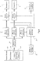
- the figure 4 represents, according to a basic block diagram, the control of electrical systems that can be implemented in one embodiment of the invention.
- the figure 4 illustrates in particular an embodiment in which the device can be electrically powered by any one of the following sources: a set of photovoltaic panels 21, a battery 22 (for example a 12v type lead-acid battery, or a battery of any another technology), or an electrical distribution network 23 (generally 110v or 220v alternating, at 50Hz or 60Hz).
- a set of photovoltaic panels 21 for example a 12v type lead-acid battery, or a battery of any another technology
- an electrical distribution network 23 generally 110v or 220v alternating, at 50Hz or 60Hz.
- the device comprises a number of electrical protections 24, for example fuses and/or circuit breakers, arranged on the electrical circuits concerned.
- electrical protections 24 for example fuses and/or circuit breakers, arranged on the electrical circuits concerned.
- a shaping of the appropriate power supply is carried out. More particularly, in the example represented here, a distinct shaping is carried out (S1) to form currents respectively adapted to the supply of the electrolyser 7, of the thermodynamic device 9, and of the electronic control device 25.
- the electronic control device 25 controls the electric currents which respectively supply the electrolyser 7 and the thermodynamic device 9. This control is based on temperature measurements supplied to the control device by the temperature sensor 10 , which provides information on the temperature of the solution, and, optionally, by a housing temperature sensor 26, which provides information on the temperature of the electronic housing of the device containing the electronic control device, in order to protect it from any overheating, especially in very high ambient temperatures.
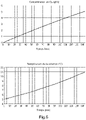
- the figure 5 represents, by two time graphs, an example of result obtained with a device in accordance with one embodiment of the invention.
- the example of the figure 5 relates to the case where the ambient temperature is very high, namely 50°C, and the initial temperature of the water of the solution is also high, namely 32°C. This corresponds to extreme conditions that can be found for example in Africa or South America.
- the device that is the subject of the invention made it possible, under these conditions, to obtain a 5 g/L solution of Cl 2 in 74 minutes.
- a state-of-the-art electrochlorination device simply could not operate under these conditions without producing too much chlorate, because the temperature of the solution would rise rapidly above 40°C.
- the figure 6 represents, by two time graphs, another example of result obtained with a device in accordance with one embodiment of the invention.
- the example of the figure 6 relates to the case where the ambient temperature is very low, namely 20°C, and the initial temperature of the water in the solution is also low, namely 5°C. This corresponds to extreme conditions that can be found in many regions of the Earth, especially in winter periods.
- the device that is the subject of the invention made it possible under these conditions to obtain a 5 g/L solution of Cl 2 in 143 minutes.
- the thermodynamic device if it is not reversible, is not activated by the control device, but the heat produced by the electrolysis and the thermal insulation of the tank allows a rise in temperature of the solution that promotes electrochlorination.
- a state-of-the-art electrochlorination device simply could not operate under these conditions, because the heat exchanges with the atmosphere will cause the temperature of the solution to drop or maintain it at a temperature that does not allow electrochlorination.
- the device that is the subject of the present invention can in particular be designed so as to be easily transportable.
- it can be configured to be stored in two suitcases.
- a first suitcase allows the transport of the thermally insulated tank, the electrolyser, the control box, the wiring, the protective equipment for the operator, the salt, the dosing equipment and the equipment necessary for the titration of the sodium hypochlorite.
- a second case contains the photovoltaic panels configured to power the device, and their support. Other distributions are of course possible. These two cases allow easy transport of the device over short distances for its implementation, and also provide protection against shocks and the hazards of transport or shipment over longer distances, by car, by plane. , or any other means of transport.
- the invention thus developed makes it possible, by the combination of a tank thermally insulated from the ambient atmosphere and of a thermal regulation device, to control the temperature of the electrolyzed solution. It is thus possible to make the solution reach a temperature compatible with effective electrochlorination and to maintain it there, which reduces the time required for the reaction.
- the device is thus compatible with operation in extreme, very hot or very cold climatic conditions.
- the present invention thus offers a water potabilization solution adapted to be implemented in varied and complex conditions, in which the known devices are ineffective, unsuitable, or even dangerous for the health of the end users.
Landscapes
- Chemical & Material Sciences (AREA)
- Chemical Kinetics & Catalysis (AREA)
- Electrochemistry (AREA)
- General Chemical & Material Sciences (AREA)
- Life Sciences & Earth Sciences (AREA)
- Hydrology & Water Resources (AREA)
- Engineering & Computer Science (AREA)
- Environmental & Geological Engineering (AREA)
- Water Supply & Treatment (AREA)
- Organic Chemistry (AREA)
- Electrolytic Production Of Non-Metals, Compounds, Apparatuses Therefor (AREA)
Applications Claiming Priority (1)
| Application Number | Priority Date | Filing Date | Title |
|---|---|---|---|
| FR2011758A FR3116270A1 (fr) | 2020-11-17 | 2020-11-17 | Dispositif de production de chlore par électrochloration. |
Publications (1)
| Publication Number | Publication Date |
|---|---|
| EP4001221A1 true EP4001221A1 (de) | 2022-05-25 |
Family
ID=74045921
Family Applications (1)
| Application Number | Title | Priority Date | Filing Date |
|---|---|---|---|
| EP21208560.9A Withdrawn EP4001221A1 (de) | 2020-11-17 | 2021-11-16 | Vorrichtung zur chlorherstellung durch elektrochlorierung |
Country Status (2)
| Country | Link |
|---|---|
| EP (1) | EP4001221A1 (de) |
| FR (1) | FR3116270A1 (de) |
Citations (4)
| Publication number | Priority date | Publication date | Assignee | Title |
|---|---|---|---|---|
| GB2202551A (en) | 1987-02-13 | 1988-09-28 | Sanden Corp | Apparatus for producing sodium hypochlorite |
| US5928505A (en) * | 1996-11-26 | 1999-07-27 | Matsushita Electric Works, Ltd. | Device for purifying and dispensing water |
| JP2000051860A (ja) * | 1998-08-07 | 2000-02-22 | Sanyo Electric Co Ltd | 電解水生成装置 |
| FR2976573A1 (fr) | 2011-06-14 | 2012-12-21 | Photalia | Procede et dispositif d’electro-chloration a partir d’une alimentation photovoltaique et pourvus de moyens de controle |
-
2020
- 2020-11-17 FR FR2011758A patent/FR3116270A1/fr active Pending
-
2021
- 2021-11-16 EP EP21208560.9A patent/EP4001221A1/de not_active Withdrawn
Patent Citations (4)
| Publication number | Priority date | Publication date | Assignee | Title |
|---|---|---|---|---|
| GB2202551A (en) | 1987-02-13 | 1988-09-28 | Sanden Corp | Apparatus for producing sodium hypochlorite |
| US5928505A (en) * | 1996-11-26 | 1999-07-27 | Matsushita Electric Works, Ltd. | Device for purifying and dispensing water |
| JP2000051860A (ja) * | 1998-08-07 | 2000-02-22 | Sanyo Electric Co Ltd | 電解水生成装置 |
| FR2976573A1 (fr) | 2011-06-14 | 2012-12-21 | Photalia | Procede et dispositif d’electro-chloration a partir d’une alimentation photovoltaique et pourvus de moyens de controle |
Also Published As
| Publication number | Publication date |
|---|---|
| FR3116270A1 (fr) | 2022-05-20 |
Similar Documents
| Publication | Publication Date | Title |
|---|---|---|
| EP4001221A1 (de) | Vorrichtung zur chlorherstellung durch elektrochlorierung | |
| EP0148756A2 (de) | System zum Aufwertem thermischer Energie mit niedrigem Niveau unter Ausnutzung der Verdampfung, und Mischung zweier strömender Medien mit gleichem Dampfdruck bei unterschiedlichen Temperaturen | |
| EP3200662B1 (de) | Abnehmbarer griff mit einem thermoelektrischen generator | |
| EP3129722A1 (de) | Vorrichtung und system zur quantifizierung der in einem tank verfügbaren nützlichen wärmeenergie | |
| EP2103565B1 (de) | Getränkeautomat, der mit einem Kühlmittel- oder Wärmeübertragungselement ausgestattet ist | |
| CA3044348C (fr) | Appareil de chauffage de type radiateur electrique incluant un convertisseur de tension | |
| EP3347112B1 (de) | Vorrichtung zur umwandlung einer flüssigkeit in dampf | |
| Rempel et al. | A model for the development of stable isotopic water signatures of tephra deposited on ice following subglacial caldera collapse | |
| FR3033057A1 (fr) | Dispositif pour la regulation de temperature | |
| FR3045139A1 (fr) | Chauffe eau plat domestique a resistances indirectes immergees | |
| FR2922001A1 (fr) | Installation de chauffage pour la production d'eau chaude sanitaire et d'eau chaude de chauffage,et dispositif utilise dans une telle installation de chauffage. | |
| EP3200663B1 (de) | Griff für einen kochbehälter mit einem latenten kühlkörper | |
| EP2590292A1 (de) | Steuerungsverfahren einer Anlage zur Erzeugung und Speicherung von erneuerbarer Energie | |
| FR2983282A1 (fr) | Installation frigorifique solaire a stockage de liquide de refroidissement sous forme solide | |
| EP3224542B1 (de) | Dampferzeuger | |
| FR3123112A1 (fr) | Dispositif réfrigérant portatif | |
| FR3052852A1 (fr) | Centrale d'energetique marethermique utilisant un systeme de ballastage, des materiaux a changement de phase et une machine thermique pour la production d'energie renouvelable | |
| WO2016062971A1 (fr) | Dispositif de distillation thermique par énergie solaire | |
| EP1156013A1 (de) | Kontinuierliches Desinfektionsverfahren gegen Legionellosis in Warmwasserversorgungseinrichtungen | |
| Anderson et al. | Arctic Sea Ice Snowmelt Onset Dates Climate Data Record Derived from Satellite Passive Microwave for 1979-2010 | |
| FR2649620A1 (fr) | Installation et procede mixte de production d'un solute et de refroidissement d'une enceinte a partir d'un fluide principal compose d'un solvant et d'un solute | |
| FR2847571A1 (fr) | Dessalement de l'eau de mer par un procede geothermique | |
| Abbood | Experimental and Theortical Study of a Solar Desalination System | |
| Krasovs' kij et al. | Electrochemical corrosion of the α-Al matrix and Mg2Si phase of new deformable aluminum alloys of the Al-Zn-Mg-Cu system in a 0.1 M solution of NaCl | |
| FR3113719A1 (fr) | Chauffe-eau électrique instantané comprenant une face avant apte à capter et émettre de la chaleur fatale perdue par la cuve de chauffe et installation |
Legal Events
| Date | Code | Title | Description |
|---|---|---|---|
| PUAI | Public reference made under article 153(3) epc to a published international application that has entered the european phase |
Free format text: ORIGINAL CODE: 0009012 |
|
| STAA | Information on the status of an ep patent application or granted ep patent |
Free format text: STATUS: THE APPLICATION HAS BEEN PUBLISHED |
|
| AK | Designated contracting states |
Kind code of ref document: A1 Designated state(s): AL AT BE BG CH CY CZ DE DK EE ES FI FR GB GR HR HU IE IS IT LI LT LU LV MC MK MT NL NO PL PT RO RS SE SI SK SM TR |
|
| STAA | Information on the status of an ep patent application or granted ep patent |
Free format text: STATUS: REQUEST FOR EXAMINATION WAS MADE |
|
| 17P | Request for examination filed |
Effective date: 20221124 |
|
| RBV | Designated contracting states (corrected) |
Designated state(s): AL AT BE BG CH CY CZ DE DK EE ES FI FR GB GR HR HU IE IS IT LI LT LU LV MC MK MT NL NO PL PT RO RS SE SI SK SM TR |
|
| STAA | Information on the status of an ep patent application or granted ep patent |
Free format text: STATUS: EXAMINATION IS IN PROGRESS |
|
| 17Q | First examination report despatched |
Effective date: 20240214 |
|
| STAA | Information on the status of an ep patent application or granted ep patent |
Free format text: STATUS: THE APPLICATION IS DEEMED TO BE WITHDRAWN |
|
| 18D | Application deemed to be withdrawn |
Effective date: 20240815 |