EP4001225A1 - Dispositif et installation compacte de séchage, en particulier de la biomasse - Google Patents
Dispositif et installation compacte de séchage, en particulier de la biomasse Download PDFInfo
- Publication number
- EP4001225A1 EP4001225A1 EP21206717.7A EP21206717A EP4001225A1 EP 4001225 A1 EP4001225 A1 EP 4001225A1 EP 21206717 A EP21206717 A EP 21206717A EP 4001225 A1 EP4001225 A1 EP 4001225A1
- Authority
- EP
- European Patent Office
- Prior art keywords
- drying
- conveying
- traction means
- carrier
- biomass
- Prior art date
- Legal status (The legal status is an assumption and is not a legal conclusion. Google has not performed a legal analysis and makes no representation as to the accuracy of the status listed.)
- Granted
Links
Images


Classifications
-
- C—CHEMISTRY; METALLURGY
- C02—TREATMENT OF WATER, WASTE WATER, SEWAGE, OR SLUDGE
- C02F—TREATMENT OF WATER, WASTE WATER, SEWAGE, OR SLUDGE
- C02F11/00—Treatment of sludge; Devices therefor
- C02F11/12—Treatment of sludge; Devices therefor by de-watering, drying or thickening
- C02F11/16—Treatment of sludge; Devices therefor by de-watering, drying or thickening using drying or composting beds
-
- F—MECHANICAL ENGINEERING; LIGHTING; HEATING; WEAPONS; BLASTING
- F26—DRYING
- F26B—DRYING SOLID MATERIALS OR OBJECTS BY REMOVING LIQUID THEREFROM
- F26B17/00—Machines or apparatus for drying materials in loose, plastic, or fluidised form, e.g. granules, staple fibres, with progressive movement
- F26B17/001—Machines or apparatus for drying materials in loose, plastic, or fluidised form, e.g. granules, staple fibres, with progressive movement the material moving down superimposed floors
- F26B17/003—Machines or apparatus for drying materials in loose, plastic, or fluidised form, e.g. granules, staple fibres, with progressive movement the material moving down superimposed floors with fixed floors provided with scrapers
-
- F—MECHANICAL ENGINEERING; LIGHTING; HEATING; WEAPONS; BLASTING
- F26—DRYING
- F26B—DRYING SOLID MATERIALS OR OBJECTS BY REMOVING LIQUID THEREFROM
- F26B25/00—Details of general application not covered by group F26B21/00 or F26B23/00
- F26B25/001—Handling, e.g. loading or unloading arrangements
- F26B25/002—Handling, e.g. loading or unloading arrangements for bulk goods
-
- F—MECHANICAL ENGINEERING; LIGHTING; HEATING; WEAPONS; BLASTING
- F26—DRYING
- F26B—DRYING SOLID MATERIALS OR OBJECTS BY REMOVING LIQUID THEREFROM
- F26B25/00—Details of general application not covered by group F26B21/00 or F26B23/00
- F26B25/04—Agitating, stirring, or scraping devices
-
- F—MECHANICAL ENGINEERING; LIGHTING; HEATING; WEAPONS; BLASTING
- F26—DRYING
- F26B—DRYING SOLID MATERIALS OR OBJECTS BY REMOVING LIQUID THEREFROM
- F26B3/00—Drying solid materials or objects by processes involving the application of heat
- F26B3/18—Drying solid materials or objects by processes involving the application of heat by conduction, i.e. the heat is conveyed from the heat source, e.g. gas flame, to the materials or objects to be dried by direct contact
- F26B3/22—Drying solid materials or objects by processes involving the application of heat by conduction, i.e. the heat is conveyed from the heat source, e.g. gas flame, to the materials or objects to be dried by direct contact the heat source and the materials or objects to be dried being in relative motion, e.g. of vibration
-
- F—MECHANICAL ENGINEERING; LIGHTING; HEATING; WEAPONS; BLASTING
- F26—DRYING
- F26B—DRYING SOLID MATERIALS OR OBJECTS BY REMOVING LIQUID THEREFROM
- F26B2200/00—Drying processes and machines for solid materials characterised by the specific requirements of the drying goods
- F26B2200/02—Biomass, e.g. waste vegetative matter, straw
-
- F—MECHANICAL ENGINEERING; LIGHTING; HEATING; WEAPONS; BLASTING
- F26—DRYING
- F26B—DRYING SOLID MATERIALS OR OBJECTS BY REMOVING LIQUID THEREFROM
- F26B2200/00—Drying processes and machines for solid materials characterised by the specific requirements of the drying goods
- F26B2200/18—Sludges, e.g. sewage, waste, industrial processes, cooling towers
Definitions
- the invention relates to a device for drying material, in particular for drying moistened or moisture-containing mass or sludge or moistened or moisture-containing parts or granules, such as metal chips or wood chips.
- the invention relates in particular to a device and a method for drying biomass, such as sewage sludge, milk sludge, brewer's grains, fermentation residues, liquid manure, animal manure or biogas manure.
- the invention also relates to a compact system with one or more such devices for drying.
- DE 103 11 554 B4 describes, for example, a device with a scraper conveyor whose scrapers are guided at a defined distance from the drying surface in order to collect sewage sludge in a defined layer thickness to distribute this.
- the drying surface can also be heated.
- the invention is based on the object of specifying a new device for drying material, in particular biomass, for example sewage sludge, in which thorough mixing of the material applied to the drying surface, in particular the biomass, is ensured.
- the drying device according to the invention is particularly suitable for drying materials such as moistened or moisture-containing mass or sludge or moistened or moisture-containing parts or granules, such as metal chips or wood chips, or biomass, such as sewage sludge, milk sludge, spent grains, fermentation residues, liquid manure, Animal manure or biogas manure trained.
- the drying device according to the invention comprises at least one drying surface (also: drying surface, drying level) onto which moisture-containing material, in particular biomass, can be spread over a large area for drying.
- conveying elements that can be moved or moved by at least one traction means are provided, which are attached at least indirectly, for example via at least one carrier arranged in between, to the at least one traction means and can be moved by it in the conveying direction .
- the conveying elements for mixing the material on the at least one drying surface are rotatably mounted with respect to the at least one traction means about at least one axis of rotation running perpendicular to the conveying direction.
- the formulation that the conveying elements are rotatably mounted with respect to the at least one traction means about at least one axis of rotation running perpendicular to the conveying direction should be understood in particular in such a way that all conveying elements on a traction means or a majority of the conveying elements on a traction means are rotatable about a common axis of rotation or that individual conveying elements, in configurations all conveying elements of the respective device, can be rotated about axes of rotation which are assigned individually to the respective conveying element.
- a rotatable bearing is understood in particular to mean a bearing that enables rotation of the respective conveying element about the respective axis of rotation over an angular range of 360°, ie in particular continuous rotation of the conveying elements.
- the conveying elements act on the at least one drying surface to distribute and mix the material.
- the formulation that the conveying elements act on or in the direction of the drying surface is to be understood in particular as any mechanical intervention that is suitable for distributing the material to be dried, in particular the biomass to be dried, on the respective drying surface and/or if necessary mixed on the respective drying surface.
- the drying surface typically extends essentially in a horizontal plane.
- several drying surfaces are provided, for example at least one upper and one lower drying surface, which in advantageous exemplary embodiments are arranged one above the other and at least overlapping in sections.
- the upper and the lower drying surface extend essentially over horizontal planes which are spaced apart from one another in the vertical direction, which planes do not necessarily have the same dimensions and can be arranged offset from one another.
- the upper and/or lower drying surface can be arranged, for example, slightly inclined with respect to a horizontal plane.
- the conveying elements that can be moved or are moved by the at least one traction means are structurally designed in such a way that they can be used for distribution and, if necessary. Aerating the material on the at least one drying surface are suitable.
- the conveying elements can be designed, for example, as paddles, rakes, rakes, tines, hooks, turning hooks or shares, in particular ploughshares or goosefoot shares.
- the conveying elements are designed, for example, as turning hooks and can in particular each have at least one turning section for distributing the biomass on the drying surfaces.
- the conveying elements are attached at least indirectly to the at least one traction means.
- Indirect attachment of the conveying elements to the traction means is to be understood in particular as attachment in which a fastening part, such as a carrier or a crossbeam carrying a plurality of conveying elements, is arranged between the traction means and the conveying elements.
- a fastening part such as a carrier or a crossbeam carrying a plurality of conveying elements
- Such a crossbeam with a plurality of conveying elements can be designed, for example, as a driver rake.
- the at least one drying surface can be heated at least in sections, preferably completely, in particular by means of a heating device.
- the heating device is designed, for example, similar to underfloor heating and, in advantageous embodiments, can be integrated at least partially, in particular completely, in the drying surface.
- the at least one drying surface is realized by a plate made of metal, in particular made of high-grade steel.
- the at least one traction means is an endless traction means, in particular a circulating traction means, for example a circulating cable, a circulating belt, a circulating belt or a circulating chain.
- the traction means are preferably driven by common drives, such as electric motors.
- At least some of the conveying elements are attached to the at least one traction means via at least one carrier.
- the conveying elements can be moved in the conveying direction by the traction mechanism.
- the at least one carrier can extend transversely to the conveying direction and/or a plurality of conveying elements can typically be fastened to each carrier.
- each carrier is designed to carry a plurality of conveying elements which are spaced apart from one another in a lateral direction transverse to the conveying direction.
- the conveying elements spaced apart from one another in the lateral direction transverse to the conveying direction can in particular be spaced apart regularly or irregularly from one another.
- the spacing of the conveying elements from one another is selected in particular in such a way that they can move freely about their respective associated axes of rotation during operation.
- each carrier carries By dimensioning the carrier and a corresponding adjustment of the number of conveying elements that each carrier carries, in particular devices can be specified which are designed to spread material, in particular biomass, evenly on drying surfaces of different sizes.
- the at least one carrier is arranged in a horizontal plane.
- the conveying elements are mounted on the at least one carrier so as to be rotatable about axes of rotation running perpendicularly to the conveying direction.
- the at least one carrier has a longitudinal axis which extends transversely to the conveying direction and about which the at least one carrier is rotatably mounted.
- the conveying elements fastened to the carrier rotate with it about its longitudinal axis.
- the conveying elements are mounted eccentrically rotatable about vertical axes of rotation with respect to the at least one traction means in such a way that the conveying elements are guided during the conveying movement over the drying surface, which extends in a horizontal plane, for example, along cyclic curves (also: cycloid, rolling curve).
- the conveying elements are thus not guided over the drying surface along linear trajectories, but instead describe curved paths in order to ensure thorough mixing of the material to be dried.
- At least one of the conveying elements is coupled via a gear to a coupling element that is anchored in a stationary manner with respect to the conveying direction in such a way that the at least one conveying element can be set into a rotational movement by moving the at least one traction means, i.e. by imparting a force acting along the at least one traction means .
- the conveying elements can be moved in the conveying direction by means of the at least one traction means and also rotated about the respective assigned axis of rotation or axes of rotation.
- a separate drive for the rotary movement can thus be avoided.
- the transmission is designed as a toothed wheel transmission.
- the transmission includes, for example, at least one gear which is in the stationary coupling element intervenes.
- the gear wheel can, for example, be connected to the carrier in a rotationally fixed manner, so that the carrier and thus the conveying elements attached thereto rotate with the gear wheel.
- the coupling element comprises a chain or toothed rail or toothed rack extending at least in sections along the conveying direction.
- the coupling element in particular the chain or toothed rail or toothed rack, is arranged in a stationary manner in space, in particular with respect to the at least one drying surface.
- the compact system according to the invention for drying material in particular for drying wood chips, metal shavings or biomass, such as sewage sludge, milk sludge, spent grains, fermentation residues, manure, animal manure, biogas manure or the like, comprises at least one of the devices described above.
- a compact system comprises at least two, preferably at least three, particularly preferably four, such devices.
- the devices are arranged one above the other in the vertical direction, in particular in such a way that material to be dried can be distributed in a cascade-like manner over the drying surfaces of the individual devices arranged one above the other.
- the compact system with the devices arranged on several levels accordingly enables the material conveyed with the aid of the devices to be dried on several drying surfaces or levels, which are arranged at a distance from one another in the vertical direction. In this way, the installation space available, particularly in the vertical direction, can be better utilized.
- the devices are arranged one above the other in the vertical direction in such a way that the drying surfaces of the devices arranged one above the other overlap at least in sections.
- the drying surfaces of the devices arranged one above the other are of this type arranged superimposed so that they overlap at least for the most part, for example more than 80%, in order to ensure better use of space.
- the superimposed arrangement is to be understood in particular with regard to the area requirement of the respective drying area with regard to a vertical projection onto a horizontal plane.
- the invention also relates to the use of the device and/or compact system described above for drying sludge, bulk material, granules or masses, in particular biomass.
- the device described above is particularly suitable for drying metal chips, wood chips, sewage sludge, milk sludge, brewer's grains, fermentation residues, manure, animal manure and/or biogas manure.
- FIG 1 shows a building unit 100 in which a compact system 50 is installed, which comprises two devices 10 arranged one above the other for drying material, in particular for drying biomass, such as sewage sludge, and optionally an elevator 40 .
- a compact system 50 which comprises two devices 10 arranged one above the other for drying material, in particular for drying biomass, such as sewage sludge, and optionally an elevator 40 .
- the following description explicitly refers to the drying of biomass.
- the device 10 or the compact system 50 is not limited to the drying of biomass.
- the device 10 or the compact system 50 is, for example, equally suitable for drying inorganic material, such as metal chips, or bulk material, such as wood chips or the like.
- Each device 10 has at least one drying surface 11, 12.
- each device 10 has an upper drying surface 11 and a lower drying surface 12 which are spaced from one another in the vertical direction.
- the upper and lower drying surfaces 11, 12 are formed in the illustrated embodiment as heatable plates, for example made of stainless steel. Biomass can be spread over the surface of the drying surfaces 11, 12 for drying, which the elevator 40 conveys during operation from a store 60 to the upper drying surface 11 of the upper device 10.
- the devices 10 are designed to distribute the conveyed biomass on the drying surfaces 11, 12 and, if necessary, to mix it.
- each device 10 has traction means 14, for example a circulating chain or a circulating cable, to which conveying elements 16 are attached directly or indirectly.
- the drying surfaces 11, 12 of the compact system 50 form a drying section for the material to be dried and can preferably be heated at least in sections.
- a comminuting device for example a shredder
- a crushing device such as a cutting rake, for crushing the dried material on the outlet side of the drying section, ie at the end of the lowest drying surface 12 of the figure 1 arranged.
- the compact system 50 comprises only one device 10.
- devices 10 with only a single drying surface 11 can also be provided.
- the traction means 14 are arranged circumferentially around the upper drying surface 11 of the respective device 10 and can be set in a circumferential movement by motor-driven drive means 18, for example motor-driven rollers or cylinders.
- the conveying elements 16 are moved in the conveying direction F by the traction means 14 over the drying surfaces 11, 12. Since the traction means 14 of each device 10 are arranged circumferentially around the respective upper drying surface 11 (also: drying level), biomass can be conveyed both over the upper drying surface 11 and over the lower drying surface 12 with the aid of the conveying elements 16 attached thereto directly or indirectly .
- the conveying elements 16 are structurally designed in such a way that they act on the biomass on the respective drying surface 11, 12 during conveying operation and in particular discharge and/or convey and/or mix it.
- the conveying elements 16 are rotatably mounted with respect to the traction means 14 so that they also rotate about axes of rotation running perpendicular to the conveying direction F during conveying operation.
- FIG 2 shows a possible embodiment of the device 10 for drying material, in particular biomass, in a schematic side view.
- the conveying elements 16 are attached to the traction means 14 indirectly via carriers 20 which extend transversely to the conveying direction F and perpendicularly to the plane of the drawing.
- the carrier 20 are perpendicular to their plane of the FIG. 2 extending longitudinal axes L rotatably mounted.
- the conveying elements 16 are designed as tines and in the exemplary embodiment shown on opposite sides of the carrier 20 arranged and rotatably attached to this. In conveying operation, the conveying elements 16 thus rotate together with the carrier 20 in the manner of a rotating driver rake.
- the traction means 14 is designed as a chain in the illustrated embodiment.
- the carriers 20 are fastened to the traction mechanism 14 and are moved by it in the conveying direction F over the drying surfaces 11, 12 during conveying or drying operation.
- Each carrier 20 is coupled via a gear 30 to a stationary anchored coupling element 34, which in the illustrated embodiment is designed as a chain, in which a gear 32 non-rotatably connected to the carrier 20 engages. Since the coupling element 34 is fixed in a stationary manner with respect to the drying surface 11, it moves in the reference system of the carrier 20 that is moved with it, counter to the conveying direction F.
- the engagement of the gear wheel 32 that is moved with it in the stationary coupling element 34 therefore imparts a torque acting about the longitudinal axis L of the carrier 20, so that the carrier 20 is rotated in the direction of rotation D during conveying operation.
- the direction of rotation of the rotary movement about the longitudinal axis L can be structurally adapted in configurations, in particular by the position of the coupling element 34 with respect to the rotary or longitudinal axis L, so that configurations are equally possible in which the conveying elements 16 via the drying surface 11 in or counter to the Rotate conveying direction F.
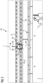
- FIG. 3 shows another embodiment of the device 10 in a plan view.
- the viewing direction is in the vertical direction onto the drying surface 11.
- the mode of operation is similar to that in the exemplary embodiment in FIG. 2 ,
- the gear 32 attached to the traction means 14 is arranged in a horizontal plane and the conveying element 16 is attached at the end to a carrier 20 which does not extend over the entire width of the drying surface 11 underneath.
- the gear 32 engages - as in the embodiment of FIG. 2 - In the coupling element 34, so that acting about the vertical axis of rotation A torque is generated by the conveying movement in the conveying direction F.
- the carrier 20 rotates with the conveying element 16 fastened to its end about the axis of rotation A.
- the conveying element 16 Since the conveying element 16 is arranged eccentrically with respect to the axis of rotation A, the conveying element 16 describes through the Overlapping with the conveying movement on the drying surface F a cyclic curve Z, which is shown in FIG. 3 is indicated by dashed lines.
Landscapes
- Engineering & Computer Science (AREA)
- Mechanical Engineering (AREA)
- General Engineering & Computer Science (AREA)
- Life Sciences & Earth Sciences (AREA)
- Microbiology (AREA)
- Hydrology & Water Resources (AREA)
- Environmental & Geological Engineering (AREA)
- Water Supply & Treatment (AREA)
- Chemical & Material Sciences (AREA)
- Organic Chemistry (AREA)
- Drying Of Solid Materials (AREA)
Applications Claiming Priority (1)
| Application Number | Priority Date | Filing Date | Title |
|---|---|---|---|
| DE102020130299.1A DE102020130299B4 (de) | 2020-11-17 | 2020-11-17 | Vorrichtung und Kompaktanlage zum Trocknen, insbesondere von Biomasse |
Publications (3)
| Publication Number | Publication Date |
|---|---|
| EP4001225A1 true EP4001225A1 (fr) | 2022-05-25 |
| EP4001225C0 EP4001225C0 (fr) | 2025-06-18 |
| EP4001225B1 EP4001225B1 (fr) | 2025-06-18 |
Family
ID=78820723
Family Applications (1)
| Application Number | Title | Priority Date | Filing Date |
|---|---|---|---|
| EP21206717.7A Active EP4001225B1 (fr) | 2020-11-17 | 2021-11-05 | Dispositif et installation compacte de séchage, en particulier de la biomasse |
Country Status (2)
| Country | Link |
|---|---|
| EP (1) | EP4001225B1 (fr) |
| DE (1) | DE102020130299B4 (fr) |
Citations (5)
| Publication number | Priority date | Publication date | Assignee | Title |
|---|---|---|---|---|
| DE1604862B1 (de) * | 1965-09-01 | 1970-10-01 | Essiccatoi F Lli Scolari Soc D | Siebboden-Trockner fuer koerniges Gut |
| DE2937644A1 (de) * | 1979-09-18 | 1981-03-19 | Erich 8069 Oberlauterbach Geilersdorfer | Einrichtung zum auflockern des hopfens in der trocknungsanlage |
| DE19836268A1 (de) * | 1998-08-11 | 2000-02-24 | Ist Anlagenbau Gmbh | Vorrichtung zum Trocknen von Schlamm und/oder von den Inhaltsstoffen verschmutzter Flüssigkeiten |
| DE10311554B4 (de) | 2003-03-17 | 2005-09-29 | Edz Bau Gmbh Edbauer Dormeyer Zizmann | Vorrichtung zum Trocknen von Klärschlamm |
| DE202019101557U1 (de) * | 2018-12-20 | 2019-04-29 | i +M GmbH & Co. KG Innovation und Management | Vorrichtung zum Trocknen von Klärschlamm |
Family Cites Families (2)
| Publication number | Priority date | Publication date | Assignee | Title |
|---|---|---|---|---|
| US5660124A (en) | 1995-09-20 | 1997-08-26 | Alar Engineering Corporation | Sludge processor |
| DE202019101031U1 (de) | 2019-02-22 | 2019-07-01 | Böhm Fertigungstechnik Suhl GmbH | Vorrichtung zum Trocknen von Biomasse und Kompaktanlage zum Trocknen von Biomasse |
-
2020
- 2020-11-17 DE DE102020130299.1A patent/DE102020130299B4/de active Active
-
2021
- 2021-11-05 EP EP21206717.7A patent/EP4001225B1/fr active Active
Patent Citations (5)
| Publication number | Priority date | Publication date | Assignee | Title |
|---|---|---|---|---|
| DE1604862B1 (de) * | 1965-09-01 | 1970-10-01 | Essiccatoi F Lli Scolari Soc D | Siebboden-Trockner fuer koerniges Gut |
| DE2937644A1 (de) * | 1979-09-18 | 1981-03-19 | Erich 8069 Oberlauterbach Geilersdorfer | Einrichtung zum auflockern des hopfens in der trocknungsanlage |
| DE19836268A1 (de) * | 1998-08-11 | 2000-02-24 | Ist Anlagenbau Gmbh | Vorrichtung zum Trocknen von Schlamm und/oder von den Inhaltsstoffen verschmutzter Flüssigkeiten |
| DE10311554B4 (de) | 2003-03-17 | 2005-09-29 | Edz Bau Gmbh Edbauer Dormeyer Zizmann | Vorrichtung zum Trocknen von Klärschlamm |
| DE202019101557U1 (de) * | 2018-12-20 | 2019-04-29 | i +M GmbH & Co. KG Innovation und Management | Vorrichtung zum Trocknen von Klärschlamm |
Also Published As
| Publication number | Publication date |
|---|---|
| DE102020130299A1 (de) | 2022-05-19 |
| EP4001225C0 (fr) | 2025-06-18 |
| DE102020130299B4 (de) | 2022-12-15 |
| EP4001225B1 (fr) | 2025-06-18 |
Similar Documents
| Publication | Publication Date | Title |
|---|---|---|
| EP3928046B1 (fr) | Dispositif de séchage de biomasse et système compact de séchage de biomasse | |
| EP1464628B1 (fr) | Système de sechage de boues provenant de stations d'épuration des eaux uséés | |
| DE3020011C2 (fr) | ||
| DE10163054B4 (de) | Streugutanlage zum Streuen von Streugut, insbesondere beleimten Holzspänen, Holzfasern oder dergleichen, auf einen Streubandförderer | |
| EP1621522B1 (fr) | Dispositif pour mélanger des substances humides | |
| DE69510533T2 (de) | Einrichtung zum fördern der aerobischen fermentierung von exkrementen, anlage mit verwendung derselben und daraus gewonnener kompost | |
| EP0104622A2 (fr) | Dispositif d'épandage de fumier, d'engrais et autres | |
| WO2020125847A1 (fr) | Dispositif de séchage de boues résiduaires | |
| WO2009033628A1 (fr) | Installation de répandage de matériau à répandre | |
| DE20304220U1 (de) | Vorrichtung zum Trocknen von Schlamm | |
| EP3927668B1 (fr) | Dispositif de séchage de biomasse et système compact de séchage de biomasse | |
| DE102020130299B4 (de) | Vorrichtung und Kompaktanlage zum Trocknen, insbesondere von Biomasse | |
| DE202020106583U1 (de) | Vorrichtung und Kompaktanlage zum Trocknen, insbesondere von Biomasse | |
| EP2233217A2 (fr) | Dispositif et procédé de séparation de matériau, notamment de fourrage vert, et utilisation correspondante | |
| DE3727451C2 (de) | Gärungsanordnung | |
| EP1053372B1 (fr) | Machine pour deplacer des meules | |
| DE202019104288U1 (de) | Vorrichtung zum Trocknen, insbesondere von Biomasse, und Kompaktanlage zum Trocknen | |
| DE202019104503U1 (de) | Vorrichtung zum Trocknen von Biomasse mit hohem Flüssigkeitsgehalt, insbesondere Gülle | |
| DE102019122001A1 (de) | Vorrichtung und Verfahren zum Trocknen von Biomasse mit hohem Flüssigkeitsgehalt, insbesondere Gülle | |
| DE202019104287U1 (de) | Vorrichtung zum Trocknen, insbesondere von Biomasse, und Kompaktanlage zum Trocknen | |
| DE2645400A1 (de) | Vorrichtung zum aufbringen von strassenbelag | |
| DE10351529A1 (de) | Vorrichtung zum dosierten Beschicken einer Anlage zur Behandlung von Feststoffen, insbesondere einer Biogasanlage, mit Feststoffen | |
| DE2905006C2 (fr) | ||
| EP0313816A1 (fr) | Epandeur, spécialement pour fumier, boues et similaires | |
| DE9319724U1 (de) | Aufgabebunker |
Legal Events
| Date | Code | Title | Description |
|---|---|---|---|
| PUAI | Public reference made under article 153(3) epc to a published international application that has entered the european phase |
Free format text: ORIGINAL CODE: 0009012 |
|
| STAA | Information on the status of an ep patent application or granted ep patent |
Free format text: STATUS: THE APPLICATION HAS BEEN PUBLISHED |
|
| AK | Designated contracting states |
Kind code of ref document: A1 Designated state(s): AL AT BE BG CH CY CZ DE DK EE ES FI FR GB GR HR HU IE IS IT LI LT LU LV MC MK MT NL NO PL PT RO RS SE SI SK SM TR |
|
| STAA | Information on the status of an ep patent application or granted ep patent |
Free format text: STATUS: REQUEST FOR EXAMINATION WAS MADE |
|
| 17P | Request for examination filed |
Effective date: 20221125 |
|
| RBV | Designated contracting states (corrected) |
Designated state(s): AL AT BE BG CH CY CZ DE DK EE ES FI FR GB GR HR HU IE IS IT LI LT LU LV MC MK MT NL NO PL PT RO RS SE SI SK SM TR |
|
| GRAP | Despatch of communication of intention to grant a patent |
Free format text: ORIGINAL CODE: EPIDOSNIGR1 |
|
| STAA | Information on the status of an ep patent application or granted ep patent |
Free format text: STATUS: GRANT OF PATENT IS INTENDED |
|
| RIC1 | Information provided on ipc code assigned before grant |
Ipc: F26B 25/00 20060101ALI20250127BHEP Ipc: F26B 25/04 20060101ALI20250127BHEP Ipc: F26B 17/00 20060101ALI20250127BHEP Ipc: F26B 3/22 20060101ALI20250127BHEP Ipc: C02F 11/16 20060101AFI20250127BHEP |
|
| INTG | Intention to grant announced |
Effective date: 20250214 |
|
| GRAS | Grant fee paid |
Free format text: ORIGINAL CODE: EPIDOSNIGR3 |
|
| GRAA | (expected) grant |
Free format text: ORIGINAL CODE: 0009210 |
|
| STAA | Information on the status of an ep patent application or granted ep patent |
Free format text: STATUS: THE PATENT HAS BEEN GRANTED |
|
| RAP3 | Party data changed (applicant data changed or rights of an application transferred) |
Owner name: BOEHM DRYRUN GMBH |
|
| AK | Designated contracting states |
Kind code of ref document: B1 Designated state(s): AL AT BE BG CH CY CZ DE DK EE ES FI FR GB GR HR HU IE IS IT LI LT LU LV MC MK MT NL NO PL PT RO RS SE SI SK SM TR |
|
| REG | Reference to a national code |
Ref country code: GB Ref legal event code: FG4D Free format text: NOT ENGLISH |
|
| REG | Reference to a national code |
Ref country code: CH Ref legal event code: EP |
|
| REG | Reference to a national code |
Ref country code: DE Ref legal event code: R096 Ref document number: 502021007769 Country of ref document: DE |
|
| REG | Reference to a national code |
Ref country code: CH Ref legal event code: EP |
|
| REG | Reference to a national code |
Ref country code: IE Ref legal event code: FG4D Free format text: LANGUAGE OF EP DOCUMENT: GERMAN |
|
| U01 | Request for unitary effect filed |
Effective date: 20250710 |
|
| U07 | Unitary effect registered |
Designated state(s): AT BE BG DE DK EE FI FR IT LT LU LV MT NL PT RO SE SI Effective date: 20250717 |
|
| PG25 | Lapsed in a contracting state [announced via postgrant information from national office to epo] |
Ref country code: GR Free format text: LAPSE BECAUSE OF FAILURE TO SUBMIT A TRANSLATION OF THE DESCRIPTION OR TO PAY THE FEE WITHIN THE PRESCRIBED TIME-LIMIT Effective date: 20250919 Ref country code: NO Free format text: LAPSE BECAUSE OF FAILURE TO SUBMIT A TRANSLATION OF THE DESCRIPTION OR TO PAY THE FEE WITHIN THE PRESCRIBED TIME-LIMIT Effective date: 20250918 |
|
| PG25 | Lapsed in a contracting state [announced via postgrant information from national office to epo] |
Ref country code: HR Free format text: LAPSE BECAUSE OF FAILURE TO SUBMIT A TRANSLATION OF THE DESCRIPTION OR TO PAY THE FEE WITHIN THE PRESCRIBED TIME-LIMIT Effective date: 20250618 |
|
| PG25 | Lapsed in a contracting state [announced via postgrant information from national office to epo] |
Ref country code: RS Free format text: LAPSE BECAUSE OF FAILURE TO SUBMIT A TRANSLATION OF THE DESCRIPTION OR TO PAY THE FEE WITHIN THE PRESCRIBED TIME-LIMIT Effective date: 20250918 |
|
| U20 | Renewal fee for the european patent with unitary effect paid |
Year of fee payment: 5 Effective date: 20251117 |
|
| PG25 | Lapsed in a contracting state [announced via postgrant information from national office to epo] |
Ref country code: IS Free format text: LAPSE BECAUSE OF FAILURE TO SUBMIT A TRANSLATION OF THE DESCRIPTION OR TO PAY THE FEE WITHIN THE PRESCRIBED TIME-LIMIT Effective date: 20251018 |
|
| PG25 | Lapsed in a contracting state [announced via postgrant information from national office to epo] |
Ref country code: SM Free format text: LAPSE BECAUSE OF FAILURE TO SUBMIT A TRANSLATION OF THE DESCRIPTION OR TO PAY THE FEE WITHIN THE PRESCRIBED TIME-LIMIT Effective date: 20250618 |
|
| PG25 | Lapsed in a contracting state [announced via postgrant information from national office to epo] |
Ref country code: CZ Free format text: LAPSE BECAUSE OF FAILURE TO SUBMIT A TRANSLATION OF THE DESCRIPTION OR TO PAY THE FEE WITHIN THE PRESCRIBED TIME-LIMIT Effective date: 20250618 |
|
| PG25 | Lapsed in a contracting state [announced via postgrant information from national office to epo] |
Ref country code: PL Free format text: LAPSE BECAUSE OF FAILURE TO SUBMIT A TRANSLATION OF THE DESCRIPTION OR TO PAY THE FEE WITHIN THE PRESCRIBED TIME-LIMIT Effective date: 20250618 |
|
| PG25 | Lapsed in a contracting state [announced via postgrant information from national office to epo] |
Ref country code: SK Free format text: LAPSE BECAUSE OF FAILURE TO SUBMIT A TRANSLATION OF THE DESCRIPTION OR TO PAY THE FEE WITHIN THE PRESCRIBED TIME-LIMIT Effective date: 20250618 |
|
| PG25 | Lapsed in a contracting state [announced via postgrant information from national office to epo] |
Ref country code: ES Free format text: LAPSE BECAUSE OF FAILURE TO SUBMIT A TRANSLATION OF THE DESCRIPTION OR TO PAY THE FEE WITHIN THE PRESCRIBED TIME-LIMIT Effective date: 20250618 |
|
| PLBE | No opposition filed within time limit |
Free format text: ORIGINAL CODE: 0009261 |
|
| STAA | Information on the status of an ep patent application or granted ep patent |
Free format text: STATUS: NO OPPOSITION FILED WITHIN TIME LIMIT |