EP4001381B1 - Verfahren zur herstellung von hochreinem biomethan - Google Patents
Verfahren zur herstellung von hochreinem biomethan Download PDFInfo
- Publication number
- EP4001381B1 EP4001381B1 EP21206402.6A EP21206402A EP4001381B1 EP 4001381 B1 EP4001381 B1 EP 4001381B1 EP 21206402 A EP21206402 A EP 21206402A EP 4001381 B1 EP4001381 B1 EP 4001381B1
- Authority
- EP
- European Patent Office
- Prior art keywords
- reactor
- biomethane
- biogas
- gaseous mixture
- production
- Prior art date
- Legal status (The legal status is an assumption and is not a legal conclusion. Google has not performed a legal analysis and makes no representation as to the accuracy of the status listed.)
- Active
Links
Images


Classifications
-
- C—CHEMISTRY; METALLURGY
- C10—PETROLEUM, GAS OR COKE INDUSTRIES; TECHNICAL GASES CONTAINING CARBON MONOXIDE; FUELS; LUBRICANTS; PEAT
- C10L—FUELS NOT OTHERWISE PROVIDED FOR; NATURAL GAS; SYNTHETIC NATURAL GAS OBTAINED BY PROCESSES NOT COVERED BY SUBCLASSES C10G OR C10K; LIQUIFIED PETROLEUM GAS; USE OF ADDITIVES TO FUELS OR FIRES; FIRE-LIGHTERS
- C10L3/00—Gaseous fuels; Natural gas; Synthetic natural gas obtained by processes not covered by subclass C10G, C10K; Liquefied petroleum gas
- C10L3/06—Natural gas; Synthetic natural gas obtained by processes not covered by C10G, C10K3/02 or C10K3/04
- C10L3/08—Production of synthetic natural gas
-
- C—CHEMISTRY; METALLURGY
- C10—PETROLEUM, GAS OR COKE INDUSTRIES; TECHNICAL GASES CONTAINING CARBON MONOXIDE; FUELS; LUBRICANTS; PEAT
- C10L—FUELS NOT OTHERWISE PROVIDED FOR; NATURAL GAS; SYNTHETIC NATURAL GAS OBTAINED BY PROCESSES NOT COVERED BY SUBCLASSES C10G OR C10K; LIQUIFIED PETROLEUM GAS; USE OF ADDITIVES TO FUELS OR FIRES; FIRE-LIGHTERS
- C10L3/00—Gaseous fuels; Natural gas; Synthetic natural gas obtained by processes not covered by subclass C10G, C10K; Liquefied petroleum gas
- C10L3/06—Natural gas; Synthetic natural gas obtained by processes not covered by C10G, C10K3/02 or C10K3/04
- C10L3/10—Working-up natural gas or synthetic natural gas
- C10L3/101—Removal of contaminants
- C10L3/106—Removal of contaminants of water
-
- C—CHEMISTRY; METALLURGY
- C10—PETROLEUM, GAS OR COKE INDUSTRIES; TECHNICAL GASES CONTAINING CARBON MONOXIDE; FUELS; LUBRICANTS; PEAT
- C10L—FUELS NOT OTHERWISE PROVIDED FOR; NATURAL GAS; SYNTHETIC NATURAL GAS OBTAINED BY PROCESSES NOT COVERED BY SUBCLASSES C10G OR C10K; LIQUIFIED PETROLEUM GAS; USE OF ADDITIVES TO FUELS OR FIRES; FIRE-LIGHTERS
- C10L2290/00—Fuel preparation or upgrading, processes or apparatus therefore, comprising specific process steps or apparatus units
- C10L2290/06—Heat exchange, direct or indirect
-
- C—CHEMISTRY; METALLURGY
- C10—PETROLEUM, GAS OR COKE INDUSTRIES; TECHNICAL GASES CONTAINING CARBON MONOXIDE; FUELS; LUBRICANTS; PEAT
- C10L—FUELS NOT OTHERWISE PROVIDED FOR; NATURAL GAS; SYNTHETIC NATURAL GAS OBTAINED BY PROCESSES NOT COVERED BY SUBCLASSES C10G OR C10K; LIQUIFIED PETROLEUM GAS; USE OF ADDITIVES TO FUELS OR FIRES; FIRE-LIGHTERS
- C10L2290/00—Fuel preparation or upgrading, processes or apparatus therefore, comprising specific process steps or apparatus units
- C10L2290/26—Composting, fermenting or anaerobic digestion fuel components or materials from which fuels are prepared
Definitions
- the present invention relates to a method for the production of high-purity biomethane from biogas.
- high-purity biomethane is understood to mean biomethane with less than 1% hydrogen (H 2 ) by volume with less than 2.5% molar carbon dioxide (CO 2 ) and less than 0.1% molar carbon monoxide (CO).
- the invention can be used in the industrial/chemical field in the renewable energy industry sector.
- Processes for the production of biomethane are disclosed in DE102014001933 , "A review on the state of the art of physical/ chemical and biological technologies for biogas upgrading”(XP03593033), “Technologies for biogas upgrading to biomethane: A review” (XP055644058), “Evaluation of process performance, energy consumption and microbiota characterization in a ceramic membrane bioreactor for ex-situ biomethanation of H 2 and CO 2 " (XP055701493), “Renewable based biogas upgrading” (XP085670709) and WO2021/234073 .
- Biogas is a renewable energy source obtained from:
- Biomethane is obtained from biogas by means of two successive steps:
- anaerobic digestion is understood to mean the degradation of biomass by bacteria in the absence of molecular oxygen.
- Biogas upgrading is a process suitable to increase the methane content in the initial biogas, obtaining biomethane which can be likened to natural gas.
- CO 2 is generally sold to other plants/companies and/or stored, for example underground, with the technique known as Carbon Capture and Storage (CCS).
- CCS Carbon Capture and Storage
- CO 2 contains carbon (C) which could be usefully converted into methane.
- the aim of the present invention is to provide a method for producing biomethane that is capable of improving the background art in one or more of the aspects mentioned above.
- an object of the invention is to provide a method for the production of biomethane that allows full utilization of the carbon contained in the initial biogas as it is.
- Another object of the invention is to devise a method for the production of biomethane in which CO 2 , which might not find a commercial use and would then have to be disposed of, is not produced.
- a further object of the present invention is to overcome the drawbacks of the background art in a manner that is alternative to any existing solutions.
- Not the least object of the invention is to provide a method for the production of biomethane that is highly reliable, relatively easy to provide and has competitive costs.
- an indicated method for the production of biomethane from biogas is the one shown schematically in Figure 1 .
- the biogas 100 is subjected to at least one biogas upgrading step, a step designated by the reference numeral 2, in Figure 1 .
- biogas 100 is understood to reference biogas purified of contaminants, such as H 2 S (hydrogen sulfide), NH 3 (ammonia), siloxanes and/or other acid/base agents and materials that may solidify and/or affect the catalytic converters mentioned hereinafter.
- contaminants such as H 2 S (hydrogen sulfide), NH 3 (ammonia), siloxanes and/or other acid/base agents and materials that may solidify and/or affect the catalytic converters mentioned hereinafter.
- the step for the production of biogas 100 occurs by producing raw biogas according to a technique known per se, such as the one shown previously, and subsequently purifying it of unwanted compounds such as hydrogen sulfide (H 2 S), ammonia (NH 3 ), water H 2 O, siloxanes and chlorine (Cl) compounds.
- biogas upgrading step consists in the methanation reaction (MET): CO 2 + 4H 2 ⁇ CH 4 + 2H 2 O.
- the CO 2 of which the biogas 100 is composed is converted through a methanation reaction, which consists in the catalytic hydrogenation of CO 2, , obtaining CH 4 and water (H 2 O).
- Figure 2 is a detailed diagram of a first embodiment of the method according to the invention.
- the method consists of two steps, which occur in two successive apparatus lines L1, L2 fluidically connected to each other.
- Each one of the apparatus lines L1, L2 comprises respectively a reactor R1, R2 and a condenser C1, C2, as explained hereinafter, which is fluidically connected to the preceding one.
- the two apparatus lines L1, L2 are arranged in series, as shown in Figure 2 .
- the biogas 100, together with hydrogen (H) 101, is introduced in the first apparatus line L1, in a first reactor R1, and the mixture crosses a catalytic converter 12 contained inside the first reactor R1.
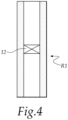
- Figure 4 shows the first reactor R1, but this illustration also exemplifies the second reactor R2, described hereinafter, which is similar to the first one.
- the supply of hydrogen (H 2 ) 101 to the first reactor R1 can occur, for example, by using electrolyzers, of a type known per se, and/or lines which carry H 2 from industrial production hubs.
- the hydrogen 101 is produced by electrolyzers connected to the first reactor R1.
- the first reactor R1 is a fixed bed reactor, made of metallic material, preferably of a metallic alloy such as one of those of the family of nickel- and chromium-based alloys known by the trade name "Inconel” and/or stainless steel.
- the reactors R1, R2 are of the fluidized bed type.
- the reactors R1, R2 operate at a temperature substantially comprised between 200°C and 350°C and at a pressure substantially comprised between 1 bar and 30 bars.
- the corresponding catalytic converters 12 of the reactors R1, R2 are provided with a fine dispersion, on ceramic supports, of active metallic material, advantageously based on one or more metals of groups 8-10 of the periodic table of elements.
- the catalytic converter 12 is, for example, based on ruthenium (Ru) and/or iron (Fe) and/or nickel (Ni) and/or cobalt (Co).
- Said catalytic converter 12 is preferably based on nickel (Ni).
- the catalytic converter 12 has a porous ceramic support, which is mechanically and thermally stable, such as alumina (Al 2 O 3 ) and/or silica (SiO 2 ) and/or titanium dioxide (TiO 2 ) and/or silicon carbide and/or other ceramic materials with a high specific surface.
- alumina Al 2 O 3
- silica SiO 2
- TiO 2 titanium dioxide
- silicon carbide silicon carbide and/or other ceramic materials with a high specific surface.
- high specific surface is understood to mean the total surface per unit of mass of the catalytic converter, with which the gas can come in contact, by both internal and external porosity.
- the catalytic converter 12 has a catalytic support made of alumina- ⁇ .
- Such a catalytic converter 12 facilitates the MET reaction and limits the development of RWGS and DR reactions and therefore the production of CO.
- the catalytic converter 12 is pretreated in a reducing environment at 600°C with H 2 , on the order of 1.9 m 3 per kilogram of catalyst.
- the gaseous mixture obtained is made to condense in a first condenser C1, in order to remove the H 2 O that prevents the further development of the reaction toward higher purities of biomethane.
- impure biomethane is understood to mean biomethane which has a volumetric percentage of H 2 greater than 1% and/or which does not meet the legal requirements for direct injection into the natural gas network.
- the gaseous mixture that exits from the first condenser C1, and from the first apparatus line L1, is injected into the second apparatus line L2, into a second reactor R2, without further additions of reagents, which is similar to the first reactor R1 and in which a second methanation reaction occurs, obtaining high-purity biomethane, i.e., with H 2 lower than 1% by volume, with CO 2 lower than 2.5% molar and with CO lower than 0.1% molar.
- the gaseous mixture that exits from the second reactor R2 is made to condense in a second condenser C2 in order to remove the H 2 O that is present.
- Biomethane 10 that meets the purity requirements necessary for injection into the natural gas network exits from the second condenser C2.
- the heat Q produced by the first reactor R1 can be used to:
- auto-thermal operation in the present description, is understood to mean that the thermal energy necessary for the operation of the reactor is obtained directly from the reaction that occurs inside it, including its outward dispersions.
- H 2 O obtained from the condensation in the first condenser C1 and in the second condenser C2 can be reused by the optional electrolyzer for the supply of hydrogen (H) 101.
- the two apparatus lines L1 and L2 are arranged in parallel and are fluidically connected, upstream of the respective reactors R1 and R2 and downstream of the respective condensers C1 and C2, by means of two four-way valves V1, V2, respectively:
- the two valves V1, V2 change position simultaneously, passing from the configuration shown in Figure 3a to the one shown in Figure 3b , and vice versa, depending on the production step, and in a sequential manner.
- Such apparatus structure makes it possible to swap periodically the reactor R1 with the reactor R2, in which the first reaction, which is the most exothermic one, occurs, in order to utilize the sensible heat accumulated inside the reactor by changing the position of the first valve V1 and of the second valve V2.
- This second embodiment of the method allows therefore a reduction of the initial apparatus costs and the operating costs due to the use of service fluids.
- the method corresponds to the one of the first embodiment described above and one obtains in output from the second condenser C2 biomethane 10 which meets the requirements for injection into the natural gas network.
- the biogas 100 and the hydrogen 101 are then injected into the second apparatus line L2, in which the first reaction step occurs, and into the second reactor R2, in which the first methanation reaction occurs.
- the second reactor R2 is heated more, while the second reaction step, with the second methanation reaction, downstream of the second condenser C2, which is less exothermic due to the lower concentration of reactants, occurs in the first apparatus line L1, inside the first reactor R1, which is already hot as a result of the previous configuration.
- the gaseous mixture Downstream of the first reactor R1, the gaseous mixture is made to condense on the first condenser C1, obtaining high-purity biomethane 10 ( Figure 3b ) to be injected into the natural gas network.
- both reactors R1 and R2 are hot, at a sufficient temperature, and it is no longer necessary to supply energy to the apparatus from the outside.
- This apparatus structure eliminates the heat exchanges between the reactors R1, R2 of the first apparatus structure and utilizes the thermal inertia of the catalytic beds, possibly modified by using also inert fillers with high thermal capacity, such as for example silicon carbide.
- the reactor R1, R2 is thermally insulated in order to work in adiabatic conditions with contact times comprised between 40 m 3 /(Kgcat ⁇ h) and 80 m 3 /(Kgcat ⁇ h) and a pressure comprised between 1 bar and 30 bars.
- the method occurs substantially by means of two successive steps, each consisting of a methanation reaction and a condensation.
- the invention achieves the intended aim and objects, utilizing the principles of the chemical equilibrium which limits the reaction in a single step, and providing a method for the production of biomethane that allows full utilization of the initial biogas.
- the invention provides a method for the production of biomethane from biogas in which CO 2 which might not find a commercial use is not produced.
- the invention provides a method for the production of biomethane from biogas in which all the carbon C contained in the CO 2 is converted into CH 4 .
- the reaction is self-sustaining in the present description is understood to mean that the reaction, once triggered, releases a quantity of heat capable of sustaining the activation energy demand of the reaction itself and the residual heat dispersions.
- the materials used may be any according to the requirements and the state of the art.
Landscapes
- Chemical & Material Sciences (AREA)
- Oil, Petroleum & Natural Gas (AREA)
- Engineering & Computer Science (AREA)
- Chemical Kinetics & Catalysis (AREA)
- General Chemical & Material Sciences (AREA)
- Organic Chemistry (AREA)
- Organic Low-Molecular-Weight Compounds And Preparation Thereof (AREA)
Claims (8)
- Ein Verfahren zur Herstellung von Biomethan (10) aus Biogas (100), wobei das Biogas (100) mindestens zwei Schritten von Biogas-Veredelung unterzogen wird, mit zwischenzeitlichem Entfernen von H2O, wobei jeder der mindestens zwei Schritte von Biogas-Veredelung in der direkten Methanisierungsreaktion des CO2 besteht, das im Biogas vorhanden ist:
CO2 + 4H2 ↔ CH4 + 2H2O,
dadurch gekennzeichnet, dass das Verfahren folgende Schritte umfasst:- das Leiten des Biogases (100) und Wasserstoffs (101) in einen ersten Reaktor (R1, R2), wobei eine erste Methanisierungsreaktion durchgeführt wird, wodurch eine erste gasförmige Mischung gewonnen wird,- das Kondensierenlassen des in der ersten gasförmigen Mischung vorhandenen H2O in einem ersten Kondensator (C1, C2), wobei das H2O vom Rest der ersten gasförmigen Mischung abgetrennt und ein unreines Biomethan gewonnen wird,- das Leiten des unreinen Biomethans in einen zweiten Reaktor (R2, R1), wobei eine zweite Methanisierungsreaktion durchgeführt wird, wodurch eine zweite gasförmige Mischung gewonnen wird,- das Kondensierenlassen des in der zweiten gasförmigen Mischung vorhandenen H2O in einem zweiten Kondensator (C2, C1), wobei das H2O vom Rest der zweiten gasförmigen Mischung abgetrennt und das Biomethan gewonnen wird (10). - Das Verfahren gemäß Anspruch 1, dadurch gekennzeichnet, dass der erste Reaktor (R1) und der zweite Reaktor (R2) einen Katalysator (12) umfassen.
- Das Verfahren gemäß Anspruch 1 oder 2, dadurch gekennzeichnet, dass der erste Reaktor (R1) und der zweite Reaktor (R2) bei einer Temperatur arbeiten, die im Wesentlichen zwischen 200°C und 350°C liegt, und bei einem Druck, der im Wesentlichen zwischen 1 bar und 30 bar beträgt.
- Das Verfahren gemäß einem oder mehreren der obigen Ansprüche, dadurch gekennzeichnet, dass die mindestens zwei Schritte in zwei aufeinander folgenden Vorrichtungslinien (L1, L2) stattfinden, die fluidisch miteinander verbunden sind, wobei jede der Vorrichtungslinien (L1, L2) einen Reaktor (R1, R2) und einen Kondensator (C1, C2) umfasst.
- Das Verfahren gemäß Anspruch 4, dadurch gekennzeichnet, dass die Vorrichtungslinien (L1, L2) seriell angeordnet sind.
- Das Verfahren gemäß Anspruch 5, dadurch gekennzeichnet, dass die von dem ersten Reaktor (R1) erzeugte Wärme (Q) genutzt wird, um- die Dissipationen in dem ersten Reaktor (R1) zu kompensieren und autothermen Betrieb zu ermöglichen- und/oder den zweiten Reaktor (R2) vorzuerhitzen.
- Das Verfahren gemäß Anspruch 4, dadurch gekennzeichnet, dass die Vorrichtungslinien (L1, L2) parallel angeordnet und fluidisch, stromaufwärts von den entsprechenden Reaktoren (R1, R2) und stromabwärts von den entsprechenden Kondensatoren (C1, C2), über zwei Vierwegeventile (V1, V2) entsprechend verbunden sind:- ein erstes Ventil (V1), stromaufwärts von den Reaktoren (R1, R2) und fluidisch damit verbunden,- ein zweites Ventil (V2), stromabwärts von den Kondensatoren (C1, C2) und fluidisch damit verbunden.
- Das Verfahren gemäß Anspruch 7, dadurch gekennzeichnet, dass es weiter den Schritt des periodischen Wechselns des Reaktors (R1, R2), in welchem die erste Methanisierungsreaktion stattfindet, mit Hilfe einer Positionsänderung des ersten Ventils (V1) und des zweiten Ventils (V2) umfasst.
Priority Applications (1)
| Application Number | Priority Date | Filing Date | Title |
|---|---|---|---|
| HRP20241741TT HRP20241741T1 (hr) | 2020-11-17 | 2021-11-04 | Postupak proizvodnje biometana visoke čistoće |
Applications Claiming Priority (1)
| Application Number | Priority Date | Filing Date | Title |
|---|---|---|---|
| IT202000027474 | 2020-11-17 |
Publications (3)
| Publication Number | Publication Date |
|---|---|
| EP4001381A1 EP4001381A1 (de) | 2022-05-25 |
| EP4001381B1 true EP4001381B1 (de) | 2024-10-09 |
| EP4001381C0 EP4001381C0 (de) | 2024-10-09 |
Family
ID=74557032
Family Applications (1)
| Application Number | Title | Priority Date | Filing Date |
|---|---|---|---|
| EP21206402.6A Active EP4001381B1 (de) | 2020-11-17 | 2021-11-04 | Verfahren zur herstellung von hochreinem biomethan |
Country Status (3)
| Country | Link |
|---|---|
| EP (1) | EP4001381B1 (de) |
| ES (1) | ES2999609T3 (de) |
| HR (1) | HRP20241741T1 (de) |
Families Citing this family (2)
| Publication number | Priority date | Publication date | Assignee | Title |
|---|---|---|---|---|
| GB2632682B (en) * | 2023-08-17 | 2026-03-25 | Aker Solutions As | Processes and systems for the production of methane |
| PL448450A1 (pl) | 2024-04-29 | 2025-11-03 | Sieć Badawcza Łukasiewicz - Instytut Nowych Syntez Chemicznych | Sposób i instalacja do oczyszczania biogazu do biometanu |
Family Cites Families (2)
| Publication number | Priority date | Publication date | Assignee | Title |
|---|---|---|---|---|
| DE102014001933A1 (de) * | 2014-02-12 | 2015-08-13 | Michael Niederbacher | Verfahren und Anlage zum Erzeugen von Biomethan |
| FR3110601B1 (fr) * | 2020-05-20 | 2022-06-10 | Tma Process | Procédé de méthanation de l’hydrogène H2et du dioxyde de carbone CO2ou de l’hydrogène H2et du monoxyde de carbone CO en vue de la production de méthane CH4 |
-
2021
- 2021-11-04 EP EP21206402.6A patent/EP4001381B1/de active Active
- 2021-11-04 HR HRP20241741TT patent/HRP20241741T1/hr unknown
- 2021-11-04 ES ES21206402T patent/ES2999609T3/es active Active
Also Published As
| Publication number | Publication date |
|---|---|
| EP4001381A1 (de) | 2022-05-25 |
| ES2999609T3 (en) | 2025-02-26 |
| HRP20241741T1 (hr) | 2025-02-28 |
| EP4001381C0 (de) | 2024-10-09 |
Similar Documents
| Publication | Publication Date | Title |
|---|---|---|
| Voitic et al. | Hydrogen production | |
| Riva et al. | Techno-economic analysis of the Ca-Cu process integrated in hydrogen plants with CO2 capture | |
| CN103476704B (zh) | 包括操作条件可选择地被调节的重整步骤的用于由碳质材料生产甲醇或烃的方法 | |
| US7470415B2 (en) | Method for producing ammonia on the basis of a nitrogen-hydrogen mixture from natural gas | |
| CA3069240C (en) | Method for the preparation of ammonia synthesis gas | |
| KR101717121B1 (ko) | 메탄올 및 암모니아의 공동 제조 | |
| DK2723676T3 (en) | PROCEDURE FOR MANUFACTURING AMMONIAK AND UREA | |
| CA2469006C (en) | Psa sharing | |
| EP4001381B1 (de) | Verfahren zur herstellung von hochreinem biomethan | |
| EP3419929B1 (de) | Durch soec optimiertes verfahren zur erzeugung von kohlenmonoxid | |
| UA119697C2 (uk) | Спосіб одержання аміаку | |
| CA3052504A1 (en) | Production of liquid hydrocarbons, biofuels and uncontaminated co2 from gaseous feedstock | |
| KR20160068122A (ko) | 코크스 오븐 가스의 수소 psa 오프가스를 이용한 수소 제조 방법 | |
| KR101953550B1 (ko) | 수소 제조 장치 및 이를 이용하여 수소를 제조하는 방법 | |
| Verma et al. | Overview of biogas reforming technologies for hydrogen production: advantages and challenges | |
| CN100404409C (zh) | 二氧化碳-甲烷重整制合成气工艺 | |
| EP4490100A1 (de) | Verfahren zur herstellung von wasserstoff und verfahren zum nachrüsten einer wasserstoffherstellungseinheit | |
| CN104388139A (zh) | 粗煤气直接甲烷化的方法和系统 | |
| Nalbant et al. | An overview of hydrogen production from biogas | |
| Piemonte et al. | Hydrogen production using inorganic membrane reactors | |
| KR20180115113A (ko) | 매립지 가스를 이용한 전력 및 화학원료 병산 시스템 | |
| CN106946637B (zh) | 一种撬装式低碳烃生产甲烷的装置及工艺 | |
| JP4165818B2 (ja) | 水素製造ハイブリッドシステム | |
| JP2000233918A (ja) | Coの製造方法 | |
| Amos | Biological water-gas shift conversion of carbon monoxide to hydrogen: Milestone completion report |
Legal Events
| Date | Code | Title | Description |
|---|---|---|---|
| REG | Reference to a national code |
Ref country code: HR Ref legal event code: TUEP Ref document number: P20241741T Country of ref document: HR |
|
| PUAI | Public reference made under article 153(3) epc to a published international application that has entered the european phase |
Free format text: ORIGINAL CODE: 0009012 |
|
| STAA | Information on the status of an ep patent application or granted ep patent |
Free format text: STATUS: THE APPLICATION HAS BEEN PUBLISHED |
|
| AK | Designated contracting states |
Kind code of ref document: A1 Designated state(s): AL AT BE BG CH CY CZ DE DK EE ES FI FR GB GR HR HU IE IS IT LI LT LU LV MC MK MT NL NO PL PT RO RS SE SI SK SM TR |
|
| STAA | Information on the status of an ep patent application or granted ep patent |
Free format text: STATUS: REQUEST FOR EXAMINATION WAS MADE |
|
| 17P | Request for examination filed |
Effective date: 20221104 |
|
| RBV | Designated contracting states (corrected) |
Designated state(s): AL AT BE BG CH CY CZ DE DK EE ES FI FR GB GR HR HU IE IS IT LI LT LU LV MC MK MT NL NO PL PT RO RS SE SI SK SM TR |
|
| P01 | Opt-out of the competence of the unified patent court (upc) registered |
Effective date: 20230528 |
|
| STAA | Information on the status of an ep patent application or granted ep patent |
Free format text: STATUS: EXAMINATION IS IN PROGRESS |
|
| 17Q | First examination report despatched |
Effective date: 20240105 |
|
| GRAP | Despatch of communication of intention to grant a patent |
Free format text: ORIGINAL CODE: EPIDOSNIGR1 |
|
| STAA | Information on the status of an ep patent application or granted ep patent |
Free format text: STATUS: GRANT OF PATENT IS INTENDED |
|
| INTG | Intention to grant announced |
Effective date: 20240503 |
|
| GRAS | Grant fee paid |
Free format text: ORIGINAL CODE: EPIDOSNIGR3 |
|
| GRAA | (expected) grant |
Free format text: ORIGINAL CODE: 0009210 |
|
| STAA | Information on the status of an ep patent application or granted ep patent |
Free format text: STATUS: THE PATENT HAS BEEN GRANTED |
|
| RAP3 | Party data changed (applicant data changed or rights of an application transferred) |
Owner name: K-INN TECH S.R.L. |
|
| AK | Designated contracting states |
Kind code of ref document: B1 Designated state(s): AL AT BE BG CH CY CZ DE DK EE ES FI FR GB GR HR HU IE IS IT LI LT LU LV MC MK MT NL NO PL PT RO RS SE SI SK SM TR |
|
| REG | Reference to a national code |
Ref country code: CH Ref legal event code: EP |
|
| REG | Reference to a national code |
Ref country code: DE Ref legal event code: R096 Ref document number: 602021019872 Country of ref document: DE |
|
| REG | Reference to a national code |
Ref country code: IE Ref legal event code: FG4D |
|
| U01 | Request for unitary effect filed |
Effective date: 20241106 |
|
| P04 | Withdrawal of opt-out of the competence of the unified patent court (upc) registered |
Free format text: CASE NUMBER: APP_60470/2024 Effective date: 20241109 |
|
| U07 | Unitary effect registered |
Designated state(s): AT BE BG DE DK EE FI FR IT LT LU LV MT NL PT RO SE SI Effective date: 20241113 |
|
| U20 | Renewal fee for the european patent with unitary effect paid |
Year of fee payment: 4 Effective date: 20241127 |
|
| REG | Reference to a national code |
Ref country code: HR Ref legal event code: ODRP Ref document number: P20241741T Country of ref document: HR Payment date: 20241220 Year of fee payment: 4 |
|
| REG | Reference to a national code |
Ref country code: ES Ref legal event code: FG2A Ref document number: 2999609 Country of ref document: ES Kind code of ref document: T3 Effective date: 20250226 |
|
| REG | Reference to a national code |
Ref country code: HR Ref legal event code: T1PR Ref document number: P20241741 Country of ref document: HR |
|
| PG25 | Lapsed in a contracting state [announced via postgrant information from national office to epo] |
Ref country code: IS Free format text: LAPSE BECAUSE OF FAILURE TO SUBMIT A TRANSLATION OF THE DESCRIPTION OR TO PAY THE FEE WITHIN THE PRESCRIBED TIME-LIMIT Effective date: 20250209 |
|
| PGFP | Annual fee paid to national office [announced via postgrant information from national office to epo] |
Ref country code: HR Payment date: 20250206 Year of fee payment: 4 |
|
| PG25 | Lapsed in a contracting state [announced via postgrant information from national office to epo] |
Ref country code: NO Free format text: LAPSE BECAUSE OF FAILURE TO SUBMIT A TRANSLATION OF THE DESCRIPTION OR TO PAY THE FEE WITHIN THE PRESCRIBED TIME-LIMIT Effective date: 20250109 |
|
| PG25 | Lapsed in a contracting state [announced via postgrant information from national office to epo] |
Ref country code: GR Free format text: LAPSE BECAUSE OF FAILURE TO SUBMIT A TRANSLATION OF THE DESCRIPTION OR TO PAY THE FEE WITHIN THE PRESCRIBED TIME-LIMIT Effective date: 20250110 |
|
| PG25 | Lapsed in a contracting state [announced via postgrant information from national office to epo] |
Ref country code: PL Free format text: LAPSE BECAUSE OF FAILURE TO SUBMIT A TRANSLATION OF THE DESCRIPTION OR TO PAY THE FEE WITHIN THE PRESCRIBED TIME-LIMIT Effective date: 20241009 |
|
| PG25 | Lapsed in a contracting state [announced via postgrant information from national office to epo] |
Ref country code: RS Free format text: LAPSE BECAUSE OF FAILURE TO SUBMIT A TRANSLATION OF THE DESCRIPTION OR TO PAY THE FEE WITHIN THE PRESCRIBED TIME-LIMIT Effective date: 20250109 |
|
| REG | Reference to a national code |
Ref country code: CH Ref legal event code: PL |
|
| PG25 | Lapsed in a contracting state [announced via postgrant information from national office to epo] |
Ref country code: SM Free format text: LAPSE BECAUSE OF FAILURE TO SUBMIT A TRANSLATION OF THE DESCRIPTION OR TO PAY THE FEE WITHIN THE PRESCRIBED TIME-LIMIT Effective date: 20241009 |
|
| PG25 | Lapsed in a contracting state [announced via postgrant information from national office to epo] |
Ref country code: MC Free format text: LAPSE BECAUSE OF FAILURE TO SUBMIT A TRANSLATION OF THE DESCRIPTION OR TO PAY THE FEE WITHIN THE PRESCRIBED TIME-LIMIT Effective date: 20241009 |
|
| REG | Reference to a national code |
Ref country code: CH Ref legal event code: PL |
|
| PG25 | Lapsed in a contracting state [announced via postgrant information from national office to epo] |
Ref country code: CH Free format text: LAPSE BECAUSE OF NON-PAYMENT OF DUE FEES Effective date: 20241130 |
|
| PG25 | Lapsed in a contracting state [announced via postgrant information from national office to epo] |
Ref country code: SK Free format text: LAPSE BECAUSE OF FAILURE TO SUBMIT A TRANSLATION OF THE DESCRIPTION OR TO PAY THE FEE WITHIN THE PRESCRIBED TIME-LIMIT Effective date: 20241009 |
|
| PG25 | Lapsed in a contracting state [announced via postgrant information from national office to epo] |
Ref country code: CZ Free format text: LAPSE BECAUSE OF FAILURE TO SUBMIT A TRANSLATION OF THE DESCRIPTION OR TO PAY THE FEE WITHIN THE PRESCRIBED TIME-LIMIT Effective date: 20241009 |
|
| PLBE | No opposition filed within time limit |
Free format text: ORIGINAL CODE: 0009261 |
|
| STAA | Information on the status of an ep patent application or granted ep patent |
Free format text: STATUS: NO OPPOSITION FILED WITHIN TIME LIMIT |
|
| 26N | No opposition filed |
Effective date: 20250710 |
|
| PG25 | Lapsed in a contracting state [announced via postgrant information from national office to epo] |
Ref country code: IE Free format text: LAPSE BECAUSE OF NON-PAYMENT OF DUE FEES Effective date: 20241104 |
|
| U20 | Renewal fee for the european patent with unitary effect paid |
Year of fee payment: 5 Effective date: 20251120 |
|
| PGFP | Annual fee paid to national office [announced via postgrant information from national office to epo] |
Ref country code: GB Payment date: 20251020 Year of fee payment: 5 |
|
| PGFP | Annual fee paid to national office [announced via postgrant information from national office to epo] |
Ref country code: ES Payment date: 20251201 Year of fee payment: 5 |
|
| PG25 | Lapsed in a contracting state [announced via postgrant information from national office to epo] |
Ref country code: HU Free format text: LAPSE BECAUSE OF FAILURE TO SUBMIT A TRANSLATION OF THE DESCRIPTION OR TO PAY THE FEE WITHIN THE PRESCRIBED TIME-LIMIT; INVALID AB INITIO Effective date: 20211104 |
|
| PG25 | Lapsed in a contracting state [announced via postgrant information from national office to epo] |
Ref country code: CY Free format text: LAPSE BECAUSE OF FAILURE TO SUBMIT A TRANSLATION OF THE DESCRIPTION OR TO PAY THE FEE WITHIN THE PRESCRIBED TIME-LIMIT; INVALID AB INITIO Effective date: 20211104 |