EP4001465A1 - Elektrolyseanordnung und verfahren - Google Patents
Elektrolyseanordnung und verfahren Download PDFInfo
- Publication number
- EP4001465A1 EP4001465A1 EP20207791.3A EP20207791A EP4001465A1 EP 4001465 A1 EP4001465 A1 EP 4001465A1 EP 20207791 A EP20207791 A EP 20207791A EP 4001465 A1 EP4001465 A1 EP 4001465A1
- Authority
- EP
- European Patent Office
- Prior art keywords
- medium
- anode
- cathode
- separator
- electrolysis
- Prior art date
- Legal status (The legal status is an assumption and is not a legal conclusion. Google has not performed a legal analysis and makes no representation as to the accuracy of the status listed.)
- Pending
Links
Images
Classifications
-
- C—CHEMISTRY; METALLURGY
- C25—ELECTROLYTIC OR ELECTROPHORETIC PROCESSES; APPARATUS THEREFOR
- C25B—ELECTROLYTIC OR ELECTROPHORETIC PROCESSES FOR THE PRODUCTION OF COMPOUNDS OR NON-METALS; APPARATUS THEREFOR
- C25B9/00—Cells or assemblies of cells; Constructional parts of cells; Assemblies of constructional parts, e.g. electrode-diaphragm assemblies; Process-related cell features
- C25B9/60—Constructional parts of cells
-
- C—CHEMISTRY; METALLURGY
- C25—ELECTROLYTIC OR ELECTROPHORETIC PROCESSES; APPARATUS THEREFOR
- C25B—ELECTROLYTIC OR ELECTROPHORETIC PROCESSES FOR THE PRODUCTION OF COMPOUNDS OR NON-METALS; APPARATUS THEREFOR
- C25B1/00—Electrolytic production of inorganic compounds or non-metals
- C25B1/01—Products
- C25B1/02—Hydrogen or oxygen
- C25B1/04—Hydrogen or oxygen by electrolysis of water
-
- C—CHEMISTRY; METALLURGY
- C25—ELECTROLYTIC OR ELECTROPHORETIC PROCESSES; APPARATUS THEREFOR
- C25B—ELECTROLYTIC OR ELECTROPHORETIC PROCESSES FOR THE PRODUCTION OF COMPOUNDS OR NON-METALS; APPARATUS THEREFOR
- C25B15/00—Operating or servicing cells
- C25B15/02—Process control or regulation
-
- C—CHEMISTRY; METALLURGY
- C25—ELECTROLYTIC OR ELECTROPHORETIC PROCESSES; APPARATUS THEREFOR
- C25B—ELECTROLYTIC OR ELECTROPHORETIC PROCESSES FOR THE PRODUCTION OF COMPOUNDS OR NON-METALS; APPARATUS THEREFOR
- C25B15/00—Operating or servicing cells
- C25B15/02—Process control or regulation
- C25B15/021—Process control or regulation of heating or cooling
-
- C—CHEMISTRY; METALLURGY
- C25—ELECTROLYTIC OR ELECTROPHORETIC PROCESSES; APPARATUS THEREFOR
- C25B—ELECTROLYTIC OR ELECTROPHORETIC PROCESSES FOR THE PRODUCTION OF COMPOUNDS OR NON-METALS; APPARATUS THEREFOR
- C25B15/00—Operating or servicing cells
- C25B15/02—Process control or regulation
- C25B15/023—Measuring, analysing or testing during electrolytic production
- C25B15/025—Measuring, analysing or testing during electrolytic production of electrolyte parameters
-
- C—CHEMISTRY; METALLURGY
- C25—ELECTROLYTIC OR ELECTROPHORETIC PROCESSES; APPARATUS THEREFOR
- C25B—ELECTROLYTIC OR ELECTROPHORETIC PROCESSES FOR THE PRODUCTION OF COMPOUNDS OR NON-METALS; APPARATUS THEREFOR
- C25B15/00—Operating or servicing cells
- C25B15/08—Supplying or removing reactants or electrolytes; Regeneration of electrolytes
-
- C—CHEMISTRY; METALLURGY
- C25—ELECTROLYTIC OR ELECTROPHORETIC PROCESSES; APPARATUS THEREFOR
- C25B—ELECTROLYTIC OR ELECTROPHORETIC PROCESSES FOR THE PRODUCTION OF COMPOUNDS OR NON-METALS; APPARATUS THEREFOR
- C25B15/00—Operating or servicing cells
- C25B15/08—Supplying or removing reactants or electrolytes; Regeneration of electrolytes
- C25B15/083—Separating products
-
- C—CHEMISTRY; METALLURGY
- C25—ELECTROLYTIC OR ELECTROPHORETIC PROCESSES; APPARATUS THEREFOR
- C25B—ELECTROLYTIC OR ELECTROPHORETIC PROCESSES FOR THE PRODUCTION OF COMPOUNDS OR NON-METALS; APPARATUS THEREFOR
- C25B15/00—Operating or servicing cells
- C25B15/08—Supplying or removing reactants or electrolytes; Regeneration of electrolytes
- C25B15/087—Recycling of electrolyte to electrochemical cell
-
- C—CHEMISTRY; METALLURGY
- C25—ELECTROLYTIC OR ELECTROPHORETIC PROCESSES; APPARATUS THEREFOR
- C25B—ELECTROLYTIC OR ELECTROPHORETIC PROCESSES FOR THE PRODUCTION OF COMPOUNDS OR NON-METALS; APPARATUS THEREFOR
- C25B9/00—Cells or assemblies of cells; Constructional parts of cells; Assemblies of constructional parts, e.g. electrode-diaphragm assemblies; Process-related cell features
- C25B9/60—Constructional parts of cells
- C25B9/67—Heating or cooling means
Definitions
- the invention is directed to an electrolysis arrangement and a method for performing an electrolysis.
- the object of the invention is to improve the prior art so that consumption of cooling water can be reduced in a particularly efficient manner.
- an electrolysis arrangement that comprises:
- the electrolysis arrangement can be used for electrolysis of a medium.
- the medium is water.
- hydrogen and oxygen can be obtained as electrolysis products.
- the electrolysis arrangement is intended to be used for an industrial scale electrolysis. For example, it is preferred that at least one of the electrolysis products is obtained at a rate of 250 to 1500 Nm 3 per hour per stack. This applies, in particular, to the production of hydrogen in the case of water electrolysis.
- the electrolysis is preferably performed in an automated way.
- the electrolysis arrangement comprises multiple stacks.
- the electrolysis arrangement comprises 2 to 16 stacks, in particular 2, 4 or 8 stacks.
- the stacks can also be referred to as electrolysis stacks.
- Each of the stacks comprises several electrolysis cells.
- Each stack has at least one stack inlet, an anode outlet and a cathode outlet.
- the medium can be provided to the stack via the stack inlet(s).
- the electrolysis of the medium can be performed using the electrolysis cells.
- an anode product and a cathode product are obtained.
- the anode product is oxygen and the cathode product is hydrogen.
- the anode product can be extracted from the stack via the anode outlet.
- the anode product will be mixed with the medium.
- a mixture of the cathode product and the medium can be extracted from the stack via the cathode outlet.
- Each of the electrolysis cells preferably comprises an anode, an anode space adjacent to the anode, a cathode and a cathode space adjacent to the cathode.
- the cathode space is preferably separated from the anode space by a membrane and, optionally also by the anode and the cathode.
- the anode outlet is preferably connected to the anode space.
- the cathode outlet is preferably connected to the cathode space.
- the membrane is preferably permeable for certain ions.
- the membrane is preferably permeable for hydrogen ions (H + ). In that case the anode and the cathode are permeable and arranged adjacent to the membrane.
- each stack has only one stack inlet, which is connected to the cathode space.
- the membrane is preferably permeable for hydroxide ions (OH).
- each of the stacks has preferably two stack inlets: a respective anode stack inlet and a respective cathode stack inlet.
- the anode stack inlet is preferably connected to the anode space.
- the cathode stack inlet is preferably connected to the cathode space.
- the electrolysis arrangement further comprises an anode separator and a cathode separator.
- the separators are configured for separating the electrolysis products from the medium.
- the separators have a respective separator inlet, a respective separator product outlet and a respective separator medium outlet. If a mixture of the product and the medium is provided at the separator inlet, the mixture is separated within the separator such that only the majority of the medium (that is >99%mol) is provided at the separator medium outlet and only the majority of the product (that is >99%mol) is provided at the separator product outlet.
- the medium is preferably liquid, while the products are preferably gaseous.
- the separators are hence preferably configured as gas/liquid separators.
- the anode outlets of the stacks are connected to the anode separator inlets. That is, the anode outlets of all stacks are connected to the anode separator inlets of the same anode separator.
- there is only one cathode separator there is only one cathode separator.
- the cathode outlets of the stacks are connected to the cathode separator inlets. That is, the cathode outlets of all stacks are connected to the cathode separator inlets of the same cathode separator.
- the medium is driven by the pump unit.
- the pump unit preferably has a variable flow. That is, the flow of the medium generated by the pump unit can be controlled, for example, by controlling the rotation speed of at least one pump of the pump unit. In case there are multiple pump units, it is preferred that the flows of the medium generated by the pump unit can be controlled independently of each other.
- the pump unit can comprise one or more pumps. In the case of more than one pump, the pumps of a pump unit are configured such that one, some or all of the pumps of this pump unit can contribute to the flow generated by this pump unit. For example, a pump unit can have two pumps, of which one pump can be active, while the other pump is used as a backup.
- both pumps of the pump unit can be used simultaneously to avoid that one of the pumps has to be operated at its maximum power.
- the electrolysis arrangement can comprise multiple pump units, each comprising multiple pumps. To that end, the electrolysis arrangement can have, for example, four pumps, of which two form a first pump unit and the other two form a second pump unit.
- the electrolysis arrangement has only one pump unit.
- the pump unit outlet is connected to all stack inlets. This does not mean that the pump unit has to be connected directly to the stack inlets.
- a means for returning excess flow to the separators to balance the feed medium flow can be arranged in between the pump unit and the stack inlets.
- a header is preferably provided for separating a flow of the medium provided by the pump unit into a respective flow of for each of the stacks. That is, by means of the header the flow of the medium is distributed to the stack inlets.
- the anode separator medium outlet and the cathode separator medium outlet are connected to a pump unit inlet. This may be via an intermediate common vessel.
- each of the stacks has only one stack inlet. This is particularly preferred in the case of PEM electrolysis cells.
- each of the stacks can have a respective anode stack inlet and a respective cathode stack inlet. This is particularly preferred in the case of alkaline electrolysis cells.
- the anode stack inlet and the cathode stack inlet of a certain stack can be jointly connected to the header.
- a respective header outlet assigned to the respective stack can be connected to both the anode stack inlet and the cathode stack inlet of this stack.
- the single feed does not only fan out to the individual stacks by means of the header, but further to the anode stack inlet and the cathode stack inlet.
- the electrolysis arrangement comprises a primary cooler for cooling the medium.
- the primary cooler is arranged between the pump unit and the stack inlets.
- the primary cooler is an air cooler. Using an air cooler as the primary cooler reduces the consumption of cooling water. If only the primary cooler is active, there is no cooling duty and hence cooling water flows can be reduced. In case the electrolysis arrangement is supposed to be operated at partial load, fans of the primary cooler can also be switched off.
- the electrolysis arrangement comprises a bypass.
- the bypass extends from a point between the pump and the primary cooler to the anode separator and/or to the cathode separator.
- the "and" case is preferred.
- the bypass preferably comprises an anode branch that is connected to the anode separator and a cathode branch that is connected to the cathode separator. Splitting the bypass into the anode branch and the cathode branch facilitates the enhanced level control of the separators.
- the anode separator and the cathode separator are preferably not connected to each other except for indirect connections via the separator outlets, via the separator inlets and/or via the bypass.
- the medium can flow from the pump unit outlet to the pump unit inlet without passing through the stacks.
- the pump unit can generate a flow that is higher than required.
- the bypass comprises a bypass valve.
- the bypass can be used to balance the medium level in the anode separator and the cathode separator.
- the anode separator and the cathode separator are preferably connected to each other only via the separator outlets, the separator inlets and/or via the bypass.
- the bypass comprises a secondary cooler for cooling the medium.
- the secondary cooler is preferably a water cooler.
- the secondary cooler is arranged upstream of where the bypass is split into the anode branch and the cathode branch. That way, the secondary cooler can cool the entire medium that flows through the bypass.
- the secondary cooler With the secondary cooler the temperature of the medium can be controlled particularly well.
- the secondary cooler can be used in addition or alternatively to the primary cooler.
- the primary cooler might have to be switched off at nighttime for noise protection. In such a situation the secondary cooler can be used alone, which may be sufficient in particular due to lower environmental temperatures at night.
- the electrolysis arrangement further comprises a return path from the bypass downstream of the secondary cooler to the stack inlets.
- the return path is a conduit that connects the bypass to the stack inlets.
- this is an indirect connection in that the return path is connected to a main conduit from the pump unit to the stack inlets.
- the return path can be connected to the main conduit between the primary cooler and the header.
- the header is part of the main conduit.
- the return path preferably begins between the secondary cooler and where the bypass splits into the anode branch and the cathode branch.
- the primary cooler and the secondary cooler are arranged parallel to each other. That means that the medium can be driven from the pump unit through either of the coolers to the stacks. This can be useful, in particular, on a hot day when the cooling power of the primary cooler might be insufficient.
- bypass and the return path respective control valves are preferably provided.
- a control valve can be provided within the return path.
- the bypass has an anode branch connected to the anode separator and a cathode branch connected to the cathode separator, wherein the anode branch and/or the cathode branch comprise a respective bypass valve.
- the "and" case is preferred.
- the flow through the bypass is controlled in one of the branches.
- the anode branch comprises a control valve, wherein the cathode branch does not.
- the cathode branch preferably comprises a flow resistance element such as an orifice.
- the stack inlets are connected to the pump unit via a header for separating a flow of the medium provided by the pump unit into a respective flow for each of the stacks, wherein the electrolysis arrangement comprises for each of the stacks a respective control valve arranged between the header and the respective stack inlet.
- a respective control valve is arranged upstream of where a common flow assigned to this stack is divided into respective flows for the stack inlets.
- a larger pressure difference between the anode space and the cathode space can drive greater amounts of the medium through the membrane. If too much of the medium is driven through the membrane, a hydrostatic imbalance between the anode separator and the cathode separator can be the result.
- a respective pressure difference between the anode space and the cathode space is smaller than 0.05 bar, in particular smaller than 0.02 bar. This pressure control can be achieved in part by the afore mentioned bypass flow to minimise hydrostatic head differences between the separators.
- the electrolysis arrangement preferably comprises a respective control valve for each of the stacks.
- the control valve is preferably arranged between the header and the stack inlet of the respective stack.
- the pump unit provides a pressure that is at least 1 bar higher than the desired pressure at the stack inlets.
- the control valves can be used to reduce the pressure.
- the electrolysis cells are configured as PEM electrolysis cells, anion exchange membrane electrolysis cells or alkaline electrolysis cells.
- PEM electrolysis cells are particularly preferred.
- the medium is water, in particular de-ionised water.
- the medium is an aqueous solution of potassium hydroxide (KOH).
- a method for performing an electrolysis of a medium in order to obtain an anode product and a cathode product using an electrolysis arrangement as described.
- the method comprises driving the medium by means of the pump unit and applying a voltage to the electrolysis cells, wherein the speed of at least one pump of the pump unit is controlled.
- the advantages and features of the described electrolysis arrangement are transferrable to the described method, and vice versa.
- the described electrolysis arrangement is preferably configured to be used according to the described method.
- the described method is preferably performed using the described electrolysis arrangement.
- a respective desired flow is determined, wherein the speed of at least one pump of the pump unit is controlled such that a flow of the medium provided by the pump unit is at least equal to the sum of the desired flows determined for the stacks and for the bypass.
- the electrolysis arrangement comprises a respective control valve for each of the stacks.
- the flow through each of the stacks can be controlled independently.
- the respective desired flow is determined based on a desired anode product output and/or a desired cathode product output.
- the "and" case is preferred.
- the desired flow of the medium through the bypass is at least equal to a predetermined minimum flow.
- bypass there is always a desired flow through the bypass. That is, at all times the bypass is supposed to have a flow that is larger than zero. The actual flow through the bypass may deviate from the desired flow.
- the purpose of the bypass is, in particular, to have a flow control that can react faster than what would be possible by adjusting the rotation speed of a pump.
- a cooling power of the primary cooler and a flow of the medium through the bypass are controlled based on a desired temperature of the medium at the stack inlets.
- the temperature of the medium at the stack inlets is influenced by the distribution of the flow through the main conduit with the primary cooler, through the bypass with the secondary cooler and through the return path. Also, the temperature of the medium at the stack inlets is influenced by the cooling power of the primary cooler and/or by the cooling power of the secondary cooler. Hence, it is preferred that all these parameters are controlled based on the desired temperature of the medium at the stack inlets.
- energy extracted from the medium by the primary cooler is at least partly recovered.
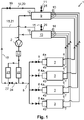
- FIG. 1 shows a preferred embodiment, to which the invention is not limited.
- the figure and the dimensions shown therein are only schematic.
- Fig. 1 shows an electrolysis arrangement 1 that comprises multiple stacks 3 of electrolysis cells.
- the electrolysis cells may be configured as PEM electrolysis cells, anion exchange membrane electrolysis cells or alkaline electrolysis cells.
- the stacks 3 each have a maximum rated DC power consumption in the range of 1 to 20 MW.
- the electrolysis arrangement 1 comprises a pump unit 2 for driving a medium.
- the pump unit 2 comprises a single pump only.
- the pump unit 2 comprises a centrifugal pump configured to provide an adjustable flow of the medium.
- Each stack 3 comprises two stack inlets 4a,4b that are connected to the pump unit 2 via a header 5 for separating a flow of the medium provided by the pump unit 2 into a respective flow for each of the stacks 3.
- Each stack 3 comprises a respective anode outlet 6 and a respective cathode outlet 7.
- the stacks 3 are configured to obtain by electrolysis of the medium introduced into the respective stack inlets 4a,4b an anode product provided together with the medium at the respective anode outlet 6 and a cathode product provided together with the medium at the respective cathode outlet 7.
- the electrolysis arrangement 1 comprises a respective control valve 8 for each of the stacks 3 arranged between the header 5 and the respective stack inlets 4a,4b, wherein the control valves 8 are configured to individually control a flow of the medium into the respective stack 3.
- the control valves 8 are configured to individually control a flow of the medium into the respective stack 3.
- the electrolysis arrangement 1 further comprises an anode separator 9 having an anode separator medium outlet 12 that is connected to the pump unit 2.
- Each of the anode outlets 6 of the stacks 3 is connected to a respective anode separator inlet 10 of the anode separator 9.
- the anode separator 9 is configured to separate the anode product from the medium introduced into the anode separator inlets 10 such that the anode product is provided at an anode separator product outlet 11 and the medium is provided at the anode separator medium outlet 12.
- the pressure of the anode separator 9 is controlled by a control valve 25.
- the electrolysis arrangement 1 further comprises a cathode separator 13 having a cathode separator medium outlet 16 that is connected to the pump unit 2.
- Each of the cathode outlets 7 of the stacks 3 is connected to a respective cathode separator inlet 14 of the cathode separator 13.
- the cathode separator 13 is configured to separate the cathode product from the medium introduced into the cathode separator inlets 14 such that the cathode product is provided at a cathode separator product outlet 15 and the medium is provided at the cathode separator medium outlet 16.
- the pressure of the cathode separator 13 is controlled by a control valve 26. The operation of the control valves 25 and 26 are such that the pressure difference is minimized between the two separators 9,13.
- the electrolysis arrangement 1 further comprises a primary cooler 22 for cooling the medium arranged between the pump unit 2 and the stack inlets 4a,4b. Also, the electrolysis arrangement 1 comprises a bypass 18 from between the pump unit 2 and the primary cooler 22 to the anode separator 9 and to the cathode separator 13. Between the pump unit 2 and where the bypass 18 begins, a filter 17 is arranged. The bypass 18 comprises a secondary cooler 23 for cooling the medium. A return path 24 connects the bypass 18 from a point downstream of the secondary cooler 23 to the header 5 and, thereby, to the stack inlets 4a,4b. By means of a control valve 27 the flow through the return path can be controlled.
- the bypass 18 has an anode branch 20 connected to the anode separator 9 and a cathode branch 21 connected to the cathode separator 13.
- the anode branch 20 comprises a bypass valve 19.
- the described electrolysis arrangement 1 comprises:
Landscapes
- Chemical & Material Sciences (AREA)
- Engineering & Computer Science (AREA)
- Metallurgy (AREA)
- Chemical Kinetics & Catalysis (AREA)
- Electrochemistry (AREA)
- Materials Engineering (AREA)
- Organic Chemistry (AREA)
- Automation & Control Theory (AREA)
- Inorganic Chemistry (AREA)
- Life Sciences & Earth Sciences (AREA)
- Sustainable Development (AREA)
- Analytical Chemistry (AREA)
- Electrolytic Production Of Non-Metals, Compounds, Apparatuses Therefor (AREA)
Priority Applications (3)
| Application Number | Priority Date | Filing Date | Title |
|---|---|---|---|
| EP20207791.3A EP4001465A1 (de) | 2020-11-16 | 2020-11-16 | Elektrolyseanordnung und verfahren |
| AU2021261959A AU2021261959A1 (en) | 2020-11-16 | 2021-11-05 | Electrolysis arrangement and method |
| CN202111383991.2A CN114574884A (zh) | 2020-11-16 | 2021-11-12 | 电解装置及方法 |
Applications Claiming Priority (1)
| Application Number | Priority Date | Filing Date | Title |
|---|---|---|---|
| EP20207791.3A EP4001465A1 (de) | 2020-11-16 | 2020-11-16 | Elektrolyseanordnung und verfahren |
Publications (1)
| Publication Number | Publication Date |
|---|---|
| EP4001465A1 true EP4001465A1 (de) | 2022-05-25 |
Family
ID=73452069
Family Applications (1)
| Application Number | Title | Priority Date | Filing Date |
|---|---|---|---|
| EP20207791.3A Pending EP4001465A1 (de) | 2020-11-16 | 2020-11-16 | Elektrolyseanordnung und verfahren |
Country Status (3)
| Country | Link |
|---|---|
| EP (1) | EP4001465A1 (de) |
| CN (1) | CN114574884A (de) |
| AU (1) | AU2021261959A1 (de) |
Families Citing this family (1)
| Publication number | Priority date | Publication date | Assignee | Title |
|---|---|---|---|---|
| EP4001464A1 (de) * | 2020-11-16 | 2022-05-25 | L'Air Liquide Société Anonyme pour l'Etude et l'Exploitation des Procédés Georges Claude | Separator für eine elektrolyseanordnung |
Citations (4)
| Publication number | Priority date | Publication date | Assignee | Title |
|---|---|---|---|---|
| US20050121315A1 (en) * | 2003-12-05 | 2005-06-09 | Baltrucki Justin D. | System for generating hydrogen and method thereof |
| US20060118428A1 (en) * | 2004-12-03 | 2006-06-08 | Baltrucki Justin D | System for generating hydrogen and method thereof |
| WO2015002953A1 (en) * | 2013-07-01 | 2015-01-08 | Sustainable Innovations, LLC | Hydrogen system and method of operation |
| WO2020160424A1 (en) * | 2019-02-01 | 2020-08-06 | Aquahydrex, Inc. | Electrochemical system with confined electrolyte |
Family Cites Families (6)
| Publication number | Priority date | Publication date | Assignee | Title |
|---|---|---|---|---|
| JP3220607B2 (ja) * | 1995-01-18 | 2001-10-22 | 三菱商事株式会社 | 水素・酸素ガス発生装置 |
| JP2004256911A (ja) * | 2003-02-05 | 2004-09-16 | Fuji Electric Advanced Technology Co Ltd | 水電解装置とその運転方法 |
| DE102009026374A1 (de) * | 2009-08-14 | 2011-02-17 | Livescreen Establishment | Verfahren und Anordnung zum Betreiben eines Verbrennungsmotors |
| WO2016068842A1 (en) * | 2014-10-27 | 2016-05-06 | Advanced Hydrogen Products, LLC | Water electrolysis systems and methods |
| JP6397396B2 (ja) * | 2015-12-28 | 2018-09-26 | デノラ・ペルメレック株式会社 | アルカリ水電解方法 |
| EP3489389A1 (de) * | 2017-11-24 | 2019-05-29 | Siemens Aktiengesellschaft | Elektrolyseeinheit und elektrolyseur |
-
2020
- 2020-11-16 EP EP20207791.3A patent/EP4001465A1/de active Pending
-
2021
- 2021-11-05 AU AU2021261959A patent/AU2021261959A1/en active Pending
- 2021-11-12 CN CN202111383991.2A patent/CN114574884A/zh active Pending
Patent Citations (5)
| Publication number | Priority date | Publication date | Assignee | Title |
|---|---|---|---|---|
| US20050121315A1 (en) * | 2003-12-05 | 2005-06-09 | Baltrucki Justin D. | System for generating hydrogen and method thereof |
| US20060118428A1 (en) * | 2004-12-03 | 2006-06-08 | Baltrucki Justin D | System for generating hydrogen and method thereof |
| WO2015002953A1 (en) * | 2013-07-01 | 2015-01-08 | Sustainable Innovations, LLC | Hydrogen system and method of operation |
| WO2020160424A1 (en) * | 2019-02-01 | 2020-08-06 | Aquahydrex, Inc. | Electrochemical system with confined electrolyte |
| US20210020975A1 (en) * | 2019-02-01 | 2021-01-21 | Aquahydrex, Inc. | Electrochemical system with confined electrolyte |
Also Published As
| Publication number | Publication date |
|---|---|
| CN114574884A (zh) | 2022-06-03 |
| AU2021261959A1 (en) | 2022-06-02 |
Similar Documents
| Publication | Publication Date | Title |
|---|---|---|
| CN111826669B (zh) | 具有宽功率波动适应性的大型电解水制氢系统及控制方法 | |
| CN113373458B (zh) | 一种波动功率输入下的质子交换膜电解水制氢系统及方法 | |
| EP4001463A1 (de) | Elektrolyseanordnung und verfahren | |
| EP1659654B1 (de) | Rekuperativer atmosphärischer SOFC/Gasturbine-Hybridkreislauf | |
| CN115939469B (zh) | 一种热电联产的一体式可再生燃料电池系统 | |
| EP4001464A1 (de) | Separator für eine elektrolyseanordnung | |
| AU2022459712B2 (en) | Hydrogen production system, and thermal management method and apparatus therefor | |
| US4879189A (en) | Fuel cell air pressurization system and method | |
| TW202405246A (zh) | 用於soec系統之大氣操作的壓縮器整合及安全操作啟動 | |
| JP3522769B2 (ja) | 燃料電池プラントの運転方法及び燃料電池プラント | |
| US10573907B2 (en) | Load-following fuel cell system with energy storage | |
| CN116121792A (zh) | 一种光伏发电直接制氢方法 | |
| CN117117975B (zh) | 一种基于低温余热利用的氢水电联产系统及方法 | |
| JP2020149838A (ja) | 高圧の燃料電池排ガスをフィルタリングする窒素ガス生成方法及び装置 | |
| AU2021261959A1 (en) | Electrolysis arrangement and method | |
| CN115404492B (zh) | 风光电源制氢装置及其制氢方法 | |
| CA2414226A1 (en) | Method for regulating the operation of fuel cell installations controlled according to heat and/or power requirement | |
| CN119800400B (zh) | 一种电制氢系统及其控制方法 | |
| TW202526097A (zh) | 用於在電解器中轉變負載之方法 | |
| WO2025169720A1 (ja) | 水電解システム | |
| CN121311629A (zh) | 用于产生氢气和/或氧气的方法和系统 | |
| Ray et al. | Fuel cell flow path design for improved efficiency and power density | |
| EP4734318A1 (de) | Hybridkraftwerk ohne emission von kohlenstoff und stickoxiden | |
| CN223016993U (zh) | 一种规模化电解水制绿氢工厂 | |
| EP4033007A1 (de) | Elektrolyseanordnung und verfahren |
Legal Events
| Date | Code | Title | Description |
|---|---|---|---|
| PUAI | Public reference made under article 153(3) epc to a published international application that has entered the european phase |
Free format text: ORIGINAL CODE: 0009012 |
|
| STAA | Information on the status of an ep patent application or granted ep patent |
Free format text: STATUS: THE APPLICATION HAS BEEN PUBLISHED |
|
| AK | Designated contracting states |
Kind code of ref document: A1 Designated state(s): AL AT BE BG CH CY CZ DE DK EE ES FI FR GB GR HR HU IE IS IT LI LT LU LV MC MK MT NL NO PL PT RO RS SE SI SK SM TR |
|
| STAA | Information on the status of an ep patent application or granted ep patent |
Free format text: STATUS: REQUEST FOR EXAMINATION WAS MADE |
|
| 17P | Request for examination filed |
Effective date: 20221018 |
|
| RBV | Designated contracting states (corrected) |
Designated state(s): AL AT BE BG CH CY CZ DE DK EE ES FI FR GB GR HR HU IE IS IT LI LT LU LV MC MK MT NL NO PL PT RO RS SE SI SK SM TR |
|
| RAP3 | Party data changed (applicant data changed or rights of an application transferred) |
Owner name: L'AIR LIQUIDE, SOCIETE ANONYME POUR L'ETUDE ET L'EXPLOITATION DES PROCEDES GEORGES CLAUDE |
|
| STAA | Information on the status of an ep patent application or granted ep patent |
Free format text: STATUS: EXAMINATION IS IN PROGRESS |
|
| 17Q | First examination report despatched |
Effective date: 20260407 |