EP4033007A1 - Elektrolyseanordnung und verfahren - Google Patents
Elektrolyseanordnung und verfahren Download PDFInfo
- Publication number
- EP4033007A1 EP4033007A1 EP21153497.9A EP21153497A EP4033007A1 EP 4033007 A1 EP4033007 A1 EP 4033007A1 EP 21153497 A EP21153497 A EP 21153497A EP 4033007 A1 EP4033007 A1 EP 4033007A1
- Authority
- EP
- European Patent Office
- Prior art keywords
- heat transfer
- transfer medium
- electrolysis
- heat
- medium path
- Prior art date
- Legal status (The legal status is an assumption and is not a legal conclusion. Google has not performed a legal analysis and makes no representation as to the accuracy of the status listed.)
- Pending
Links
Images



Classifications
-
- C—CHEMISTRY; METALLURGY
- C25—ELECTROLYTIC OR ELECTROPHORETIC PROCESSES; APPARATUS THEREFOR
- C25B—ELECTROLYTIC OR ELECTROPHORETIC PROCESSES FOR THE PRODUCTION OF COMPOUNDS OR NON-METALS; APPARATUS THEREFOR
- C25B1/00—Electrolytic production of inorganic compounds or non-metals
- C25B1/01—Products
- C25B1/02—Hydrogen or oxygen
- C25B1/04—Hydrogen or oxygen by electrolysis of water
-
- C—CHEMISTRY; METALLURGY
- C25—ELECTROLYTIC OR ELECTROPHORETIC PROCESSES; APPARATUS THEREFOR
- C25B—ELECTROLYTIC OR ELECTROPHORETIC PROCESSES FOR THE PRODUCTION OF COMPOUNDS OR NON-METALS; APPARATUS THEREFOR
- C25B15/00—Operating or servicing cells
- C25B15/02—Process control or regulation
- C25B15/021—Process control or regulation of heating or cooling
-
- C—CHEMISTRY; METALLURGY
- C25—ELECTROLYTIC OR ELECTROPHORETIC PROCESSES; APPARATUS THEREFOR
- C25B—ELECTROLYTIC OR ELECTROPHORETIC PROCESSES FOR THE PRODUCTION OF COMPOUNDS OR NON-METALS; APPARATUS THEREFOR
- C25B15/00—Operating or servicing cells
- C25B15/08—Supplying or removing reactants or electrolytes; Regeneration of electrolytes
-
- C—CHEMISTRY; METALLURGY
- C25—ELECTROLYTIC OR ELECTROPHORETIC PROCESSES; APPARATUS THEREFOR
- C25B—ELECTROLYTIC OR ELECTROPHORETIC PROCESSES FOR THE PRODUCTION OF COMPOUNDS OR NON-METALS; APPARATUS THEREFOR
- C25B9/00—Cells or assemblies of cells; Constructional parts of cells; Assemblies of constructional parts, e.g. electrode-diaphragm assemblies; Process-related cell features
- C25B9/60—Constructional parts of cells
- C25B9/67—Heating or cooling means
Definitions
- the invention is directed to an electrolysis arrangement and to an electrolysis method, in particular for hydrogen production on an industrial scale.
- known systems for the electrolysis of water stacks of electrolysis cells are used that are supposed to be operated at a particular temperature. If the actual temperature deviates significantly from the desired temperature, the efficiency is reduced or the stacks may be damaged, in particular due to cell voltage peaks. Hence, if operated at a high load, cooling of the stacks may be required to compensate for heat generated by the cells of the stacks themselves. If operated at a low load, however, heating may be required.
- known electrolysis systems comprise a heat exchanger flown through by the water that is supplied to the cells/stacks. Therein, heat can be exchanged between the water and a heat transfer medium.
- the water can be cooled if the heat transfer medium has a lower temperature and the water can be heated if the heat transfer medium has a higher temperature.
- the temperature of the heat transfer medium cannot be adjusted immediately. That is, the known systems have a slow dynamic response.
- the dynamic response can be different depending on the electrolysis medium and the specific heat capacity. For example, the temperature in PEM electrolysis cells usually rises faster than in alkaline electrolysis cells.
- the object of the invention is to improve the prior art so that the temperature of an electrolysis stack can be controlled more reliably, in particular in case of a change in the load of the electrolysis stack.
- the electrolysis arrangement comprises:
- the electrolysis arrangement can be used for electrolysis of a medium.
- the medium is liquid, in particular water.
- the electrolysis medium can be water only.
- the medium may be water that contains dissolved salts such as KOH for alkaline electrolysis or electrolysis using anion exchange membrane cells.
- the electrolysis products are preferably gaseous. In the case of water, hydrogen and oxygen can be obtained as the electrolysis products.
- the electrolysis arrangement is intended to be used for an industrial scale electrolysis. For example, it is preferred that at least one of the electrolysis products is obtained at a rate of 250 to 1500 Nm 3 per hour per electrolysis stack. This applies, in particular, to the production of hydrogen in the case of water electrolysis.
- the electrolysis is preferably performed in an automated way.
- the electrolysis arrangement comprises one electrolysis stack. That is, it is possible that the electrolysis arrangement has more than one electrolysis stack.
- the electrolysis stacks each have a maximum rated DC power consumption in the range of 1 to 20 MW, in particular in the range of 3 to 10 MW.
- the described electrolysis arrangement is preferably used for industrial scale electrolysis. In particular, this is to be understood in contrast to experimental setups on a laboratory scale.
- the industrial scale can be quantified in terms of the maximum rated DC power consumption of the electrolysis stacks.
- the maximum rated DC power consumption is what is commonly used to describe the electrolysis stacks. For example, a "5 MW electrolysis stack" has a maximum rated DC power consumption of 5 MW.
- the electrolysis stack is preferably configured to be operated at a temperature in the range of 50 to 120°C, in particular at 90 °C. Hence, it is desirable to provide the electrolysis medium at a respective temperature to the electrolysis stack.
- the electrolysis medium can be supplied to the electrolysis stack via a feed installation.
- the feed installation is configured as a single feed line.
- the feed installation can comprise multiple independent feed lines.
- the feed installation comprises one or more separators.
- the feed installation can be part of a circuit, via which the electrolysis medium can be circulated.
- the electrolysis medium together with an anode product of the electrolysis can be guided from the anode of the electrolysis stack to an anode separator, where the anode product can be separated from the electrolysis medium.
- the electrolysis medium together with a cathode product of the electrolysis can be guided from the cathode of the electrolysis stack to a cathode separator, where the cathode product can be separated from the electrolysis medium. From the separators the electrolysis medium can be guided back to the electrolysis stack via a feed line that, together with the separators, is part of the feed installation.
- the feed installation is configured as a feed line that has two branches, one of which being connected to the anode space and the other one being connected to the cathode space. It is also possible that the feed installation comprises multiple feed line branches that merge into a single feed line.
- a first of these branches can be connected to the anode separator and a second of these branches can be connected to the cathode separator. Downstream of where the branches merge the feed line can be connected to the electrolysis stack as a single line or as two branches.
- a first heat exchanger and, optionally, also a second heat exchanger are integrated. That means that the electrolysis medium flowing through the feed installation passes the heat exchanger(s) such that heat can be exchanged between the electrolysis medium and a heat exchange medium supplied to the heat exchanger(s). It is preferred that the heat exchanger(s) is/are integrated into a feed line that is part of the feed installation. In particular, it is preferred that the heat exchanger(s) is/are integrated into a feed line that extends from an anode separator and/or from a cathode separator to the electrolysis stack.
- the heat exchanger(s) are preferably arranged between the anode separator and/or the cathode separator on the one hand and the electrolysis stack on the other hand.
- the heat exchanger(s) is/are arranged within the anode separator and/or the cathode separator.
- the first embodiment there is at least one heat exchanger.
- This heat exchanger is what has been referred to as the "first heat exchanger" above. However, since here the same heat exchanger is part of both the first heat transfer medium path and the second heat transfer medium path, there is no need for a numbering of heat exchangers. In view of the costs it is preferred in the first embodiment to have exactly one heat exchanger.
- This heat exchanger is preferably integrated into a feed line of the feed installation. In particular, it is preferred that the heat exchanger is integrated into a feed line that extends from an anode separator and/or from a cathode separator to the electrolysis stack. It is also possible that multiple heat exchangers are provided that are each part of both the first heat transfer medium path and the second heat transfer medium path.
- first heat exchangers are provided in such a case.
- these multiple heat exchangers are not referred to as a first, second, ... heat exchanger.
- one heat exchanger can be integrated into the anode separator and one heat exchanger can be integrated into the cathode separator, wherein both these heat exchangers are part of both the first heat transfer medium path and the second heat transfer medium path.
- the electrolysis arrangement comprises two paths for a heat transfer medium. Both heat transfer medium paths are supposed to be used with the same heat transfer medium.
- the heat transfer medium is preferably water.
- the first heat transfer medium path extends at least between the heat sink and the heat exchanger.
- the second heat transfer medium path extends at least between the heat source and the heat exchanger. It is possible that a section of the first heat transfer medium path and a section of the second heat transfer medium path share a conduit such as a pipe. That is, it is not necessary that the first heat transfer medium path and the second heat transfer medium path can be distinguished from each other at every point. It is sufficient that the first heat transfer medium path and the second heat transfer medium path are not completely identical.
- the first heat transfer medium path includes at least one section exclusive to the first heat transfer medium and the second heat transfer medium path includes at least one section exclusive to the second heat transfer medium path.
- the first heat transfer medium path can be used to supply the heat transfer medium from the heat sink to the heat exchanger. Thereby, the electrolysis medium can be cooled.
- This can be used in a cooling mode. In the cooling mode, preferably a flow rate of the heat transfer medium flowing through the first heat transfer medium path is higher than a flow rate of the heat transfer medium flowing through the second heat transfer medium path. In particular, it is preferred that only the first heat transfer medium path is used. It is thereby sufficient for the heat sink to be active.
- the heat source can be inactive.
- the second heat transfer medium path can be used to supply the heat transfer medium from the heat source to the heat exchanger. Thereby, the electrolysis medium can be heated. This can be used in a heating mode.
- a flow rate of the heat transfer medium flowing through the first heat transfer medium path is lower than a flow rate of the heat transfer medium flowing through the second heat transfer medium path.
- the heat sink can thereby be inactive.
- the electrolysis arrangement comprises two paths for a heat transfer medium.
- the first heat transfer medium path and the second heat transfer medium path can be entirely separated from each other.
- the first heat transfer medium path is used with a first heat transfer medium and that the second heat transfer medium path is used with a second heat transfer medium, which is different from the first heat transfer medium.
- both heat transfer medium paths are used with the same heat transfer medium, preferably water.
- the first heat transfer medium path extends at least between the heat sink and the first heat exchanger.
- the second heat transfer medium path extends at least between the heat source and the second heat exchanger.
- first heat exchanger there is at least one first heat exchanger and at least one second heat exchanger.
- first heat exchanger and the second heat exchanger are preferably integrated into a feed line of the feed installation.
- first heat exchanger and the second heat exchanger are integrated into a feed line that extends from an anode separator and/or from a cathode separator to the electrolysis stack.
- multiple first heat exchangers are provided that are each part of the first heat transfer medium path and/or that multiple second heat exchangers are provided that are each part of the second heat transfer medium path.
- one heat exchanger can be integrated into the anode separator and one heat exchanger can be integrated into the cathode separator, wherein both these heat exchangers are part of the first heat transfer medium path.
- These two heat exchangers constitute two first heat exchangers.
- one heat exchanger can be integrated into the anode separator and one heat exchanger can be integrated into the cathode separator, wherein both these heat exchangers are part of the second heat transfer medium path.
- These two heat exchangers constitute two second heat exchangers. In this example, there is a total of four heat exchangers.
- first embodiment at least one heat exchanger is provided that is part of both the first heat transfer medium path and the second heat transfer medium path.
- the heat sink is preferably an active heat sink, in particular an air cooler.
- the heat sink preferably can be switched on and off such that the heat transfer medium that passes the heat sink is cooled only in case the heat sink is active.
- the heat source is preferably an active heat source, in particular an electric heater. The heat source preferably can be switched on and off such that the heat transfer medium that passes the heat source is heated only in case the heat source is active.
- the first heat transfer medium path is configured as a circuit and/or the second heat transfer medium path is configured as a circuit.
- the "and" case is preferred.
- a circuit is a closed loop. That is, the heat transfer medium can be circulated through the respective heat transfer medium path. To that end the heat transfer medium can be reused, which reduces the consumption of the heat transfer medium.
- the first heat transfer medium path could, for example, extend from a river to the (first) heat exchanger. Water as the (first) heat transfer medium could thereby be taken from the river and supplied to the (first) heat exchanger. From the (first) heat exchanger the first heat transfer medium path could lead to a drain, for example of a public waste water network.
- the second heat transfer medium path could, for example, extend from a steam source to the (second) heat exchanger.
- the steam source can be configured for a process such as methanol synthesis.
- Steam as the (second) heat transfer medium could thereby be taken from the steam source and supplied to the (second) heat exchanger. From the (second) heat exchanger the steam could be exhausted to the environment.
- the first heat transfer medium path and the second heat transfer medium path partly overlap such that the heat source is also part of the first heat transfer medium path.
- the first heat transfer medium path comprises the heat sink and the heat source
- the second heat transfer medium path comprises the heat source, but not the heat sink. That is, the heat sink is arranged in a part of the first heat transfer medium path that is exclusive to the first heat transfer medium path.
- the overlap of the first heat transfer medium path with the second heat transfer medium path reduces the required amount of piping. If the heat source is switched off, the heat transfer medium flowing through the first heat transfer medium path can pass the heat source without being affected.
- the first heat transfer medium path can be used for cooling, despite the fact that the first heat transfer medium path includes also the heat source.
- the first heat transfer medium path and the second heat transfer medium path partly overlap such that a pump unit is part of both the first heat transfer medium path and the second heat transfer medium path.
- a single pump unit is sufficient for both heat transfer medium paths. This reduces the costs of the electrolysis arrangement. It is sufficient that the pump unit comprises a single pump.
- the first heat transfer medium path and the second heat transfer medium path partly overlap, wherein a three-way control valve is provided where the first heat transfer medium path and the second heat transfer medium path separate from each other and/or where the first heat transfer medium path and the second heat transfer medium path merge. It is preferred that only one three-way control valve is provided.
- the three-way control valve can be used to switch between usage of the first heat transfer medium path and the second heat transfer medium path. This can be done in a gradual manner. That is, depending on the setting of the three-way control valve the heat transfer medium can flow through the first heat transfer medium path only, through both the first heat transfer medium path and the second heat transfer medium path or through the second heat transfer medium path only.
- the fraction of the heat transfer medium flowing through the two heat transfer medium paths can be selected freely by gradually adjusting the three-way control valve.
- the three-way control valve can be configured such that the entire heat transfer medium can only flow through one of the two heat transfer medium paths.
- the three-way control valve In the cooling mode the three-way control valve is set such that the entire heat transfer medium flows through the first heat transfer medium path. Thereby, the heat transfer medium flows through the second heat transfer medium path only to the extent that the first heat transfer medium path and the second heat transfer medium path overlap.
- the three-way control valve In the heating mode the three-way control valve is set such that the entire heat transfer medium flows through the second heat transfer medium path. Thereby, the heat transfer medium flows through the first heat transfer medium path only to the extent that the first heat transfer medium path and the second heat transfer medium path overlap.
- the three-way control valve In between the cooling mode and the heating mode there can be a transition mode in which the three-way control valve is set such that a part of the heat transfer medium flows through the first heat transfer medium path and the other part of the heat transfer medium flows through the second heat transfer medium path.
- the first heat transfer medium path further comprises a storage vessel.
- the storage vessel can be used to store the heat transfer medium. Thereby, a reserve of the heat transfer medium is provided within the first heat transfer medium path. After switching out of the cooling mode, the heat sink can remain active for a period of time. Thereby, a reserve of cooled heat transfer medium can be obtained that can be stored in the storage vessel.
- the first heat transfer medium path can comprises an expansion vessel.
- a single vessel can be used as a storage and expansion vessel.
- the first heat transfer medium path is longer than the second heat transfer medium path.
- the present embodiment can be realized by the first heat transfer medium path being configured as a circuit and the second heat transfer medium path being configured as a circuit, wherein the first heat transfer medium path comprises a section shared with the second heat transfer medium path and a bypass of the heat sink.
- the heat source is preferably arranged in the section shared by the first heat transfer medium path and the second heat transfer medium path.
- a method for performing an electrolysis of an electrolysis medium in an electrolysis stack, wherein in a cooling mode the electrolysis medium is cooled prior to the electrolysis by a first heat transfer medium provided in a first heat transfer medium path that includes a heat sink, and wherein in a heating mode the electrolysis medium is heated prior to the electrolysis by the first heat transfer medium provided in a second heat transfer medium path, which further includes a heat source, or by a second heat transfer medium provided in a second heat transfer medium path that includes a heat source.
- the advantages and features of the described electrolysis arrangement are transferrable to the method, and vice versa.
- the electrolysis arrangement is preferably configured to be used according to the method.
- the electrolysis is performed using an electrolysis arrangement configured as described.
- the method can be performed as follows: In a cooling mode the electrolysis medium is cooled prior to the electrolysis by a heat transfer medium provided in the first heat transfer medium path that includes the heat sink. In a heating mode the electrolysis medium is heated prior to the electrolysis by the heat transfer medium provided in the second heat transfer medium path, which further includes the heat source.
- a cooling mode the electrolysis medium is cooled prior to the electrolysis by a heat transfer medium provided in the first heat transfer medium path that includes the heat sink.
- a heating mode the electrolysis medium is heated prior to the electrolysis by the heat transfer medium provided in the second heat transfer medium path, which further includes the heat source.
- only one heat transfer medium is used. Hence, there is no need for a numbering of heat transfer media. Both the cooling and the heating can be achieved using the same heat exchanger.
- the method can be performed as follows: In a cooling mode the electrolysis medium is cooled prior to the electrolysis by a first heat transfer medium provided in the first heat transfer medium path that includes the heat sink. In a heating mode the electrolysis medium is heated prior to the electrolysis by a second heat transfer medium provided in a second heat transfer medium path that includes a heat source.
- the cooling can be achieved using the first heat exchanger, the heating can be achieved using the second heat exchanger.
- the heating mode is used for a startup of the electrolysis stack.
- the operation of the electrolysis stack can be started. This applies to a first time use of a new electrolysis stack as well as to a case in which an electrolysis stack had been out of service, for example for maintenance purposes.
- the electrolysis stack is brought to its operation temperature. In the present embodiment, this is done using the heating mode. Thus, there is no need for equipment designated to the startup only.
- the heating mode can be used in order to tighten bolts that are used to hold the electrolysis cells of the electrolysis stack together. At an elevated temperature the bolts can be tightened particularly securely.
- the heating mode can be used to avoid freezing of the first heat transfer medium path and/or of the electrolysis stack if the electrolysis arrangement is shut down.
- the first heat transfer medium path can be protected using the heating mode by directing a small amount of the heat transfer medium from the heat source through the first heat transfer medium path.
- the first heat transfer medium has a temperature in the range of 40 to 80 °C when being used for cooling the electrolysis medium and/or in the heating mode the first heat transfer medium or the second heat transfer medium, respectively, has a temperature in the range of 50 to 110 °C when being used for heating the electrolysis medium.
- the temperatures provided for the cooling mode and heating mode refer to the temperature of the one heat transfer medium used in both modes.
- the temperature provided for the cooling mode refers to the first heat transfer medium and the temperature provided for the heating mode refers to the second heat transfer medium.
- the (first) heat transfer medium In the cooling mode the (first) heat transfer medium has a comparatively high temperature. Nevertheless, it is preferred that after having been used for cooling, the (first) heat transfer medium has a temperature below 100 °C. This refers to the temperature at the outlet of the (first) heat exchanger. In the heating mode the (first or second) heat transfer medium has a comparatively low temperature. This reduces the time to switch between the cooling mode and the heating mode.
- the first heat transfer medium enters the first heat exchanger at a temperature that differs by less than 15 °C from a temperature at which the first heat transfer medium leaves the first heat exchanger, and/or the second heat transfer medium enters the second heat exchanger at a temperature that differs by less than 15 °C from a temperature at which the second heat transfer medium leaves the second heat exchanger.
- the first alternative is applicable, according to which the (first) heat transfer medium enters the (first) heat exchanger at a temperature that differs by less than 15 °C from a temperature at which the (first) heat transfer medium leaves the (first) heat exchanger.
- both alternatives are applicable. Therein, the "and" case is preferred.
- the heat exchanger(s) is/are configured for only a comparatively small change in temperature. This is in line with the previously described embodiment, according to which the heat transfer medium/media has/have a comparatively high temperature in the cooling mode and a comparatively low temperature in the heating mode. Hence, also in the present embodiment the time to switch between the cooling mode and the heating mode is particularly short.
- the cooling mode is used if a temperature of the electrolysis medium prior to the electrolysis is detected to be above a first temperature threshold value and/or wherein the heating mode is used if the temperature of the electrolysis medium prior to the electrolysis is detected to be below a second temperature threshold value.
- the "and" case is preferred.
- the decision whether the cooling mode or the heating mode is used is made in view of the temperature of the electrolysis medium.
- the electrolysis stack is supposed to be operated at an operation temperature. For example, this can be 90 °C.
- a set point for the temperature of the electrolysis medium prior to the electrolysis is chosen.
- the cooling mode or the heating mode are used.
- the first temperature threshold and the second temperature threshold can both be equal to the set point. In that case, if the measured temperature of the electrolysis medium is higher than the set point, the cooling mode is applied in order to reduce the temperature of the electrolysis medium. In case the measured temperature of the electrolysis medium is lower than the set point, the heating mode is applied in order to increase the temperature of the electrolysis medium.
- the first temperature threshold value can be higher than the set point and the second temperature threshold value can be lower than the set point.
- the three-way control valve can be set such that the entire flow of the heat transfer medium is directed through the first heat transfer medium path comprising the heat sink, which is active. Once less extensive cooling is required, the cooling power generated by the heat sink can be reduced, for example by reducing the fan speed of an air cooler used as the heat sink. Once a fan speed of zero has been reached and in case the temperature of the electrolysis medium is still lower than desired, it can be switched from the cooling mode to an intermediate mode.
- the three-way control valve can be gradually opened such that part of the heat transfer medium is guided through the second heat transfer medium path so as to bypass the heat sink.
- the more the three-way control valve is opened in this way the less will the electrolysis medium be cooled.
- the heating mode is reached. Therein, the heat source is activated. The higher the heating power of the heat source is set, the more will the electrolysis medium be heated.
- the cooling mode is used if a load of the electrolysis stack is detected to be above a first threshold value and/or wherein the heating mode is used if the load of the electrolysis stack is detected to be below a second threshold value.
- the "and" case is preferred.
- the decision whether the cooling mode or the heating mode is used is made in view of the load of the electrolysis stack. Therein, it is assumed that at high loads a cooling is required and that at low loads a heating is required.
- the first threshold and the second threshold can be equal to each other.
- the temperature of the electrolysis medium prior to the electrolysis is controlled by adjusting a cooling power of the heat sink and/or wherein in the heating mode the temperature of the electrolysis medium prior to the electrolysis is controlled by adjusting a hating power of the heat source.
- the "and" case is preferred.
- the temperature of the electrolysis medium is controlled based on a measurement of the temperature of the electrolysis medium.
- the temperature of the electrolysis medium can be controlled by adjusting a fan speed of an air cooler used as the heat sink. If the fan speed approaches zero, it can be assumed that the heat loss of the electrolysis stack is approximately equal to the heat generation of the electrolysis stack.
- the temperature of the electrolysis medium can be controlled by adjusting an electrical current flowing through an electric heater used as the heat sink.
- Fig. 1 shows an electrolysis arrangement 1 comprising an electrolysis stack 2 and a feed installation 3 for supplying an electrolysis medium to the electrolysis stack 2.
- the feed installation 3 is configured as a feed line 18.
- the electrolysis arrangement 1 comprises a first heat transfer medium path 4 for providing a first heat transfer medium from a heat sink 6 to a first heat exchanger 8 integrated into the feed line 18 of the feed installation 3.
- the electrolysis medium in the feed line 18 of the feed installation 3 can be cooled.
- the electrolysis arrangement 1 comprises a second heat transfer medium path 5 for providing a second heat transfer medium from a heat source 7 to a second heat exchanger 9 integrated into the feed line 18 of the feed installation 3.
- the electrolysis medium in the feed installation 3 can be heated.
- a cooing mode only the first heat transfer medium path 4 is active.
- In a heating mode only the second heat transfer medium path 5 is active.
- Fig. 2 shows an electrolysis arrangement 1 similar to the one shown in Fig. 1 .
- the feed line 18 downstream of the second heat exchanger 9 splits into a first branch 19 and a second branch 20.
- the first branch 19 can be connected to an anode space of the electrolysis stack 2 and the second branch 20 can be connected to a cathode space of the electrolysis stack 2.
- Fig. 3 shows an electrolysis arrangement 1 comprising an electrolysis stack 2 and a feed installation 3 for supplying an electrolysis medium to the electrolysis stack 2.
- the feed installation 3 is configured as a feed line 18.
- the electrolysis arrangement 1 comprises a first heat transfer medium path 4 for providing a heat transfer medium from a heat sink 6 to a heat exchanger 8 integrated into the feed line 18 of the feed installation 3.
- the first heat transfer medium path 4 extends from the heat sink 6 to the heat exchanger 8.
- the electrolysis medium in the feed line 18 of the feed installation 3 can be cooled.
- the electrolysis arrangement 1 comprises a second heat transfer medium path 5 for providing the heat transfer medium (i.e.
- the second heat transfer medium path 5 extends from a point outside the first heat transfer medium path 4 via the heat source 7 to the heat exchanger 8. Between the heat source 7 and the heat exchanger 8 the two heat transfer medium paths 4,5 overlap.
- the electrolysis medium in the feed installation 3 can be heated. In a cooling mode only the heat sink 6 is active. In a heating mode only the heat source 7 is active.
- Fig. 4 shows an electrolysis arrangement 1 similar to the one shown in Fig. 3 .
- the feed line 18 downstream of the heat exchanger 8 splits into a first branch 19 and a second branch 20.
- the first branch 19 can be connected to an anode space of the electrolysis stack 2 and the second branch 20 can be connected to a cathode space of the electrolysis stack 2.
- Fig. 5 shows a further embodiment of an electrolysis arrangement 1 that is similar to the ones shown in Fig. 1 and 2 .
- the feed installation 3 comprises an anode separator 13, a cathode separator besides the feed line 18.
- the feed line 18 comprises a first branch 19 connected to the anode separator 13 and a second branch 20 connected to the cathode separator 20. Downstream of the separators 13,14 the branches 19,20 merge such that a the feed line 18 is connected to the electrolysis stack 2 as a single line.
- a respective first heat exchanger 8 is integrated into the anode separator 13 and into the cathode separator 14.
- a respective second heat exchanger 9 is integrated into the anode separator 13 and into the cathode separator 14. That is, in total four heat exchangers 8,9 are provided.
- Fig. 6 shows a further embodiment of an electrolysis arrangement 1 that is similar to the ones shown in Fig. 3 and 4 .
- the feed installation 3 comprises an anode separator 13, a cathode separator besides the feed line 18.
- the feed line 18 comprises a first branch 19 connected to the anode separator 13 and a second branch 20 connected to the cathode separator 20. Downstream of the separators 13,14 the branches 19,20 merge such that a the feed line 18 is connected to the electrolysis stack 2 as a single line.
- a respective heat exchanger 8 is integrated into the anode separator 13 and into the cathode separator 14. That is, in total two heat exchangers 8 are provided. In order to avoid confusion with the other embodiments, however, these two heat exchangers 8 are not referred to as a first and second heat exchanger.
- Both the embodiments according to Fig. 5 and 6 can be altered in particular in the following two ways (not shown in the figures).
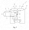
- Fig. 7 shows a further embodiment of an electrolysis arrangement 1.
- the electrolysis arrangement 1 comprises an electrolysis stack 2 connected to a feed installation 3 for supplying an electrolysis medium to the electrolysis stack 2.
- the electrolysis medium can be transferred together with the electrolysis products to an anode separator 13 and a cathode separator 14.
- the anode and cathode products of the electrolysis can be separated from the electrolysis medium.
- oxygen can be extracted at an oxygen outlet 15 of the anode separator 13 and hydrogen at a hydrogen outlet 16 of the cathode separator 14.
- new electrolysis medium can be supplied into the electrolysis arrangement 1 via an inlet 17.
- a heat exchanger 8 is integrated into the feed installation 3 . Similar to Fig. 2 , the heat exchanger 8 is part of a first heat transfer medium path 4 and a second heat transfer medium path 5 that partly overlap.
- the first heat transfer medium path 4 and the second heat transfer medium path 5 are configured as a respective circuit such that a heat transfer medium can be circulated through the first heat transfer medium path 4 or the second heat transfer medium path 5, respectively.
- the first heat transfer medium path 4 comprises an air cooler as a heat sink 6, a storage vessel 12 for storing the heat transfer medium, a pump unit 10 and an electric heater as a heat source 7.
- the pump unit 10 and the heat source 7 are also part of the second heat transfer medium path 5.
- a three-way control valve 11 is provided where the first heat transfer medium path 4 and the second heat transfer medium path 5 separate from each other.
- the first heat transfer medium path 4 is longer than the second heat transfer medium path 5.
- the electrolysis medium in the feed installation 3 can be cooled.
- Fig. 7 the heat sink 6 is active and the heat source 7 is inactive.
- the three-way control valve 11 is set such that the heat transfer medium flows through the first heat transfer medium path 4.
- the second heat transfer medium path 5 is flown through by the heat transfer medium only to the extent that the first heat transfer medium path 4 and the second heat transfer medium path 5 overlap.
- a dotted line it is indicated that the part of the second heat transfer medium path 5 that is exclusive to the second heat transfer medium path 5 is closed.
- the heat transfer medium has a temperature in the range of 40 to 80 °C when being used for cooling the electrolysis medium, that is when entering the heat exchanger 8.
- the heat transfer medium enters the heat exchanger 8 at a temperature that is less than 15 °C lower than a temperature at which the heat transfer medium leaves the heat exchanger 8.
- Fig. 8 shows the electrolysis arrangement 1 of Fig. 7 in a heating mode.
- the electrolysis medium in the feed installation 3 can be heated.
- the heat sink 6 is inactive and the heat source 7 is active.
- the three-way control valve 11 is set such that the heat transfer medium flows through the second heat transfer medium path 5.
- the first heat transfer medium path 4 is flown through by the heat transfer medium only to the extent that the first heat transfer medium path 4 and the second heat transfer medium path 5 overlap.
- the heat transfer medium has a temperature in the range of 50 to 1 10 °C when being used for heating the electrolysis medium, that is when entering the heat exchanger 8.
- the heat transfer medium enters the heat exchanger 8 at a temperature that is less than 15 °C higher than a temperature at which the heat transfer medium leaves the heat exchanger 8.
- the heating mode can be used, in particular, for a startup of the electrolysis stack 2.
- the cooling mode illustrated in Fig. 7 can be used if a temperature of the electrolysis medium prior to the electrolysis is detected to be above a first temperature threshold value and the heating mode illustrated in Fig. 8 can used if the temperature of the electrolysis medium prior to the electrolysis is detected to be below a second temperature threshold value.
- the cooling mode illustrated in Fig. 7 can be used if a load of the electrolysis stack 2 is detected to be above a first load threshold value and the heating mode illustrated in Fig. 8 can be used if the load of the electrolysis stack 2 is detected to be below a second load threshold value.
- the temperature of the electrolysis medium prior to the electrolysis can be controlled by adjusting a cooling power of the heat sink 6 and in the heating mode the temperature of the electrolysis medium prior to the electrolysis can be controlled by adjusting a hating power of the heat source 7.
- the electrolysis arrangement 1 can be switched particularly quickly between the heating mode and the cooling mode. This is because only part of the heat transfer medium has to be heated up when switching into the heating mode.
Landscapes
- Chemical & Material Sciences (AREA)
- Engineering & Computer Science (AREA)
- Chemical Kinetics & Catalysis (AREA)
- Electrochemistry (AREA)
- Materials Engineering (AREA)
- Metallurgy (AREA)
- Organic Chemistry (AREA)
- Automation & Control Theory (AREA)
- Inorganic Chemistry (AREA)
- Electrolytic Production Of Non-Metals, Compounds, Apparatuses Therefor (AREA)
Priority Applications (1)
| Application Number | Priority Date | Filing Date | Title |
|---|---|---|---|
| EP21153497.9A EP4033007A1 (de) | 2021-01-26 | 2021-01-26 | Elektrolyseanordnung und verfahren |
Applications Claiming Priority (1)
| Application Number | Priority Date | Filing Date | Title |
|---|---|---|---|
| EP21153497.9A EP4033007A1 (de) | 2021-01-26 | 2021-01-26 | Elektrolyseanordnung und verfahren |
Publications (1)
| Publication Number | Publication Date |
|---|---|
| EP4033007A1 true EP4033007A1 (de) | 2022-07-27 |
Family
ID=74285268
Family Applications (1)
| Application Number | Title | Priority Date | Filing Date |
|---|---|---|---|
| EP21153497.9A Pending EP4033007A1 (de) | 2021-01-26 | 2021-01-26 | Elektrolyseanordnung und verfahren |
Country Status (1)
| Country | Link |
|---|---|
| EP (1) | EP4033007A1 (de) |
Citations (4)
| Publication number | Priority date | Publication date | Assignee | Title |
|---|---|---|---|---|
| JPH07126883A (ja) * | 1993-11-05 | 1995-05-16 | Agency Of Ind Science & Technol | 太陽エネルギーを利用した水の電解装置及び電解方法 |
| US20070000789A1 (en) * | 2005-06-30 | 2007-01-04 | Libby Cara S | Integrated hydrogen production and processing system and method of operation |
| US20180287179A1 (en) * | 2015-04-08 | 2018-10-04 | Sunfire Gmbh | Heat management method in a high-temperature steam electrolysis (soec), solid oxide fuel cell (sofc) and/or reversible high-temperature fuel cell (rsoc), and high-temperature steam electrolysis (soec), solid oxide fuel cell (sofc) and/or reversible high-temperature fuel cell (rsoc) arrangement |
| US20190360110A1 (en) * | 2018-05-24 | 2019-11-28 | Honda Motor Co., Ltd. | Method of operating water electrolysis system and water electrolysis system |
-
2021
- 2021-01-26 EP EP21153497.9A patent/EP4033007A1/de active Pending
Patent Citations (4)
| Publication number | Priority date | Publication date | Assignee | Title |
|---|---|---|---|---|
| JPH07126883A (ja) * | 1993-11-05 | 1995-05-16 | Agency Of Ind Science & Technol | 太陽エネルギーを利用した水の電解装置及び電解方法 |
| US20070000789A1 (en) * | 2005-06-30 | 2007-01-04 | Libby Cara S | Integrated hydrogen production and processing system and method of operation |
| US20180287179A1 (en) * | 2015-04-08 | 2018-10-04 | Sunfire Gmbh | Heat management method in a high-temperature steam electrolysis (soec), solid oxide fuel cell (sofc) and/or reversible high-temperature fuel cell (rsoc), and high-temperature steam electrolysis (soec), solid oxide fuel cell (sofc) and/or reversible high-temperature fuel cell (rsoc) arrangement |
| US20190360110A1 (en) * | 2018-05-24 | 2019-11-28 | Honda Motor Co., Ltd. | Method of operating water electrolysis system and water electrolysis system |
Similar Documents
| Publication | Publication Date | Title |
|---|---|---|
| CA2752436C (en) | Back-up fuel cell electric generator comprising a compact manifold body, methods of managing the operation thereof | |
| CN109461952B (zh) | 一种船用燃料电池热电联供系统 | |
| KR101967488B1 (ko) | 연료 전지 디바이스에서의 동작 상태를 제어하는 방법 및 장치 | |
| US20250171911A1 (en) | Hydrogen production system, and thermal management method and apparatus therefor | |
| US8586257B2 (en) | Fuel cell system that provides high grade heat to an absorption chiller | |
| US11641019B1 (en) | Fuel cell system, and method of its operation | |
| CN110739470B (zh) | 一种燃料电池辅助系统 | |
| TW202405246A (zh) | 用於soec系統之大氣操作的壓縮器整合及安全操作啟動 | |
| JP2012018823A (ja) | 燃料電池システム及びその運転方法 | |
| KR102237506B1 (ko) | 연료 전지를 갖는 발전 시스템을 동작시키기 위한 방법 및 제어 서브시스템 | |
| CN117223133A (zh) | 具有冷却系统的电池动力设备 | |
| CN116344861A (zh) | 一种质子交换膜氢燃料电池热电联产系统 | |
| CN115404492B (zh) | 风光电源制氢装置及其制氢方法 | |
| US20230317979A1 (en) | Fuel cell, system comprising a fuel cell and method for controlling the system | |
| KR102819518B1 (ko) | 연료전지 냉각 시스템 및 그 제어방법 | |
| TW202526097A (zh) | 用於在電解器中轉變負載之方法 | |
| EP4109604B1 (de) | Abgasabwärmerückgewinnungssystem | |
| JP2020136041A (ja) | 燃料電池システム | |
| CN115986170A (zh) | 用于多堆燃料电池系统的电堆故障处理方法 | |
| EP4001465A1 (de) | Elektrolyseanordnung und verfahren | |
| CN219716907U (zh) | 多堆燃料电池系统 | |
| JP2022157510A (ja) | 燃料電池システムの運転方法 | |
| US20180069250A1 (en) | Fuel cell system and its operation method | |
| KR20260060349A (ko) | 전해조에서 부하를 전이하기 위한 방법 | |
| JP2026500871A (ja) | 電気分解装置と電気エネルギー貯蔵装置との組み合わせ |
Legal Events
| Date | Code | Title | Description |
|---|---|---|---|
| PUAI | Public reference made under article 153(3) epc to a published international application that has entered the european phase |
Free format text: ORIGINAL CODE: 0009012 |
|
| STAA | Information on the status of an ep patent application or granted ep patent |
Free format text: STATUS: THE APPLICATION HAS BEEN PUBLISHED |
|
| AK | Designated contracting states |
Kind code of ref document: A1 Designated state(s): AL AT BE BG CH CY CZ DE DK EE ES FI FR GB GR HR HU IE IS IT LI LT LU LV MC MK MT NL NO PL PT RO RS SE SI SK SM TR |
|
| STAA | Information on the status of an ep patent application or granted ep patent |
Free format text: STATUS: REQUEST FOR EXAMINATION WAS MADE |
|
| 17P | Request for examination filed |
Effective date: 20221018 |
|
| RBV | Designated contracting states (corrected) |
Designated state(s): AL AT BE BG CH CY CZ DE DK EE ES FI FR GB GR HR HU IE IS IT LI LT LU LV MC MK MT NL NO PL PT RO RS SE SI SK SM TR |
|
| RAP3 | Party data changed (applicant data changed or rights of an application transferred) |
Owner name: L'AIR LIQUIDE, SOCIETE ANONYME POUR L'ETUDE ET L'EXPLOITATION DES PROCEDES GEORGES CLAUDE |
|
| STAA | Information on the status of an ep patent application or granted ep patent |
Free format text: STATUS: EXAMINATION IS IN PROGRESS |
|
| 17Q | First examination report despatched |
Effective date: 20250430 |