EP4001574B1 - Gebäudetür und türband für eine gebäudetür - Google Patents
Gebäudetür und türband für eine gebäudetür Download PDFInfo
- Publication number
- EP4001574B1 EP4001574B1 EP21187713.9A EP21187713A EP4001574B1 EP 4001574 B1 EP4001574 B1 EP 4001574B1 EP 21187713 A EP21187713 A EP 21187713A EP 4001574 B1 EP4001574 B1 EP 4001574B1
- Authority
- EP
- European Patent Office
- Prior art keywords
- door
- wing
- hinge
- building
- door leaf
- Prior art date
- Legal status (The legal status is an assumption and is not a legal conclusion. Google has not performed a legal analysis and makes no representation as to the accuracy of the status listed.)
- Active
Links
Images




Classifications
-
- E—FIXED CONSTRUCTIONS
- E05—LOCKS; KEYS; WINDOW OR DOOR FITTINGS; SAFES
- E05D—HINGES OR SUSPENSION DEVICES FOR DOORS, WINDOWS OR WINGS
- E05D5/00—Construction of single parts, e.g. the parts for attachment
- E05D5/02—Parts for attachment, e.g. flaps
- E05D5/06—Bent flaps
-
- E—FIXED CONSTRUCTIONS
- E05—LOCKS; KEYS; WINDOW OR DOOR FITTINGS; SAFES
- E05D—HINGES OR SUSPENSION DEVICES FOR DOORS, WINDOWS OR WINGS
- E05D11/00—Additional features or accessories of hinges
- E05D11/0054—Covers, e.g. for protection
-
- E—FIXED CONSTRUCTIONS
- E05—LOCKS; KEYS; WINDOW OR DOOR FITTINGS; SAFES
- E05D—HINGES OR SUSPENSION DEVICES FOR DOORS, WINDOWS OR WINGS
- E05D7/00—Hinges or pivots of special construction
- E05D7/04—Hinges adjustable relative to the wing or the frame
- E05D7/0415—Hinges adjustable relative to the wing or the frame with adjusting drive means
- E05D7/0423—Screw-and-nut mechanisms
-
- E—FIXED CONSTRUCTIONS
- E06—DOORS, WINDOWS, SHUTTERS, OR ROLLER BLINDS IN GENERAL; LADDERS
- E06B—FIXED OR MOVABLE CLOSURES FOR OPENINGS IN BUILDINGS, VEHICLES, FENCES OR LIKE ENCLOSURES IN GENERAL, e.g. DOORS, WINDOWS, BLINDS, GATES
- E06B1/00—Border constructions of openings in walls, floors, or ceilings; Frames to be rigidly mounted in such openings
- E06B1/04—Frames for doors, windows, or the like to be fixed in openings
- E06B1/52—Frames specially adapted for doors
-
- E—FIXED CONSTRUCTIONS
- E06—DOORS, WINDOWS, SHUTTERS, OR ROLLER BLINDS IN GENERAL; LADDERS
- E06B—FIXED OR MOVABLE CLOSURES FOR OPENINGS IN BUILDINGS, VEHICLES, FENCES OR LIKE ENCLOSURES IN GENERAL, e.g. DOORS, WINDOWS, BLINDS, GATES
- E06B3/00—Window sashes, door leaves, or like elements for closing wall or like openings; Layout of fixed or moving closures, e.g. windows in wall or like openings; Features of rigidly-mounted outer frames relating to the mounting of wing frames
- E06B3/02—Wings made completely of glass
-
- E—FIXED CONSTRUCTIONS
- E05—LOCKS; KEYS; WINDOW OR DOOR FITTINGS; SAFES
- E05D—HINGES OR SUSPENSION DEVICES FOR DOORS, WINDOWS OR WINGS
- E05D5/00—Construction of single parts, e.g. the parts for attachment
- E05D5/02—Parts for attachment, e.g. flaps
- E05D5/06—Bent flaps
- E05D2005/067—Bent flaps gooseneck shaped
-
- E—FIXED CONSTRUCTIONS
- E05—LOCKS; KEYS; WINDOW OR DOOR FITTINGS; SAFES
- E05D—HINGES OR SUSPENSION DEVICES FOR DOORS, WINDOWS OR WINGS
- E05D7/00—Hinges or pivots of special construction
- E05D7/04—Hinges adjustable relative to the wing or the frame
- E05D2007/0476—Pocket hinges
-
- E—FIXED CONSTRUCTIONS
- E05—LOCKS; KEYS; WINDOW OR DOOR FITTINGS; SAFES
- E05Y—INDEXING SCHEME ASSOCIATED WITH SUBCLASSES E05D AND E05F, RELATING TO CONSTRUCTION ELEMENTS, ELECTRIC CONTROL, POWER SUPPLY, POWER SIGNAL OR TRANSMISSION, USER INTERFACES, MOUNTING OR COUPLING, DETAILS, ACCESSORIES, AUXILIARY OPERATIONS NOT OTHERWISE PROVIDED FOR, APPLICATION THEREOF
- E05Y2600/00—Mounting or coupling arrangements for elements provided for in this subclass
- E05Y2600/40—Mounting location; Visibility of the elements
- E05Y2600/41—Concealed
- E05Y2600/412—Concealed in the rabbet
-
- E—FIXED CONSTRUCTIONS
- E05—LOCKS; KEYS; WINDOW OR DOOR FITTINGS; SAFES
- E05Y—INDEXING SCHEME ASSOCIATED WITH SUBCLASSES E05D AND E05F, RELATING TO CONSTRUCTION ELEMENTS, ELECTRIC CONTROL, POWER SUPPLY, POWER SIGNAL OR TRANSMISSION, USER INTERFACES, MOUNTING OR COUPLING, DETAILS, ACCESSORIES, AUXILIARY OPERATIONS NOT OTHERWISE PROVIDED FOR, APPLICATION THEREOF
- E05Y2600/00—Mounting or coupling arrangements for elements provided for in this subclass
- E05Y2600/50—Mounting methods; Positioning
- E05Y2600/52—Toolless
- E05Y2600/526—Gluing or cementing
-
- E—FIXED CONSTRUCTIONS
- E05—LOCKS; KEYS; WINDOW OR DOOR FITTINGS; SAFES
- E05Y—INDEXING SCHEME ASSOCIATED WITH SUBCLASSES E05D AND E05F, RELATING TO CONSTRUCTION ELEMENTS, ELECTRIC CONTROL, POWER SUPPLY, POWER SIGNAL OR TRANSMISSION, USER INTERFACES, MOUNTING OR COUPLING, DETAILS, ACCESSORIES, AUXILIARY OPERATIONS NOT OTHERWISE PROVIDED FOR, APPLICATION THEREOF
- E05Y2800/00—Details, accessories and auxiliary operations not otherwise provided for
- E05Y2800/67—Materials; Strength alteration thereof
- E05Y2800/672—Glass
-
- E—FIXED CONSTRUCTIONS
- E05—LOCKS; KEYS; WINDOW OR DOOR FITTINGS; SAFES
- E05Y—INDEXING SCHEME ASSOCIATED WITH SUBCLASSES E05D AND E05F, RELATING TO CONSTRUCTION ELEMENTS, ELECTRIC CONTROL, POWER SUPPLY, POWER SIGNAL OR TRANSMISSION, USER INTERFACES, MOUNTING OR COUPLING, DETAILS, ACCESSORIES, AUXILIARY OPERATIONS NOT OTHERWISE PROVIDED FOR, APPLICATION THEREOF
- E05Y2900/00—Application of doors, windows, wings or fittings thereof
- E05Y2900/10—Application of doors, windows, wings or fittings thereof for buildings or parts thereof
- E05Y2900/13—Type of wing
- E05Y2900/132—Doors
Definitions
- the invention relates to a building door with a door frame, an unrebated door leaf, in particular made of glass, and at least one door hinge with which the door leaf is pivotably connected to the door frame, wherein the door leaf extends in a vertical direction in a closed position and along a door leaf width in a first horizontal direction, wherein the door frame has a reveal on one hinge side with a reveal surface, a rebate step and a boundary surface laterally adjacent to the door leaf in the closed position, wherein a shoulder section facing an inner side of the door leaf on the rebate step connects the reveal surface and the boundary surface to one another, wherein a frame body of the door hinge is inserted into a recess in the reveal and wherein a part of a leaf body of the door hinge is arranged within the recess in the closed position.
- the building door is particularly suitable as an interior door and in particular as a room door.
- the unrebated leaf can be formed in a particularly simple manner from a plate-shaped material, with glass being the preferred material and being provided as a plate or pane with a usually uniform or essentially uniform thickness.
- the thickness of the door leaf can be between 6 mm and 20 mm for example in a glass design, although other plate-shaped materials can also be considered.
- Building doors with an unrebated door leaf and in particular with a glass door leaf with the features described at the beginning are made of DE 10 2017 100 252 B3 , DE 10 2017 100 254 B3 , DE 10 2017 100 270 B3 and DE 20 2017 100 143 U1 known.
- the glass door leaf is clamped in a particularly simple manner at its edge by a leaf body of the door hinge, whereby the leaf body surrounds the edge of the door leaf in a U-shape and thus extends on an outer side, an inner side and the associated edge of the door leaf.
- the inner side of the door leaf faces the step section and is usually also in contact with it via a seal.
- the door leaf can be swung open towards its outer side.
- the state of the art also describes that the door leaf is approximately flush with one end face of the door frame or is set back from the end face ( Fig. 3 from DE 10 2017 100 254 B3 ). This results in a high-quality appearance, in which the door hinges are integrated relatively unobtrusively into the overall picture due to their compact design.
- the building door usually has two hinges, which are preferably designed identically, to ensure uniform support of the door leaf on the door frame. It is therefore sufficient, both in terms of the state of the art and in terms of the invention itself, to explain the structure and functioning of one of the hinges.
- the recess is formed in the reveal.
- the recess is located in the reveal surface and in the boundary surface, which are aligned parallel to each other with an offset. In the closed position, the leaf body is immersed partially into the recess. This means that when the inside of the door leaf is viewed in the closed position, only part of the door hinge is visible.
- the FR 2 324 839 A1 reveals a building door with a glass door leaf. Door hinges are attached to the door leaf by clamping on both sides.
- the leaf body does not extend to the outside of the door leaf.
- the door leaf therefore forms a continuous, uninterrupted and uncovered surface in the area of at least one door hinge on the outside, which results in a particularly high-quality appearance of the building door.
- the leaf body is arranged and fastened exclusively on the inside of the door leaf. This also results in a uniform or essentially uniform gap on the corresponding side of the door leaf. Except in such a narrow gap between the door leaf and the surrounding boundary surface or possibly through the door leaf, the leaf body is not visible when looking at the outside of the door leaf. In particular, if the door leaf is matt, opaque and/or colored, the entire door hinge is invisible or practically invisible when looking at the outside of the door leaf. Even if the door leaf is made of clear glass, the door hinge is largely inserted into the recess in the closed position and is not or at most barely noticeable, especially when the color is matched.
- gluing can be carried out.
- High-strength adhesives are available to the specialist with which door leaves made of glass or other plate-shaped materials can be securely glued to the leaf body, which is usually made of metal. It should be noted that the typical weight of the door leaf is between 10 kg and 100 kg, in particular between 15 kg and 50 kg.
- the at least one door hinge of the building door is particularly inconspicuous and preferably almost invisible even when looking at the inside of the door leaf in the closed position.
- the sash body in the closed position protrudes less than 10 mm along the first horizontal direction relative to the reveal surface and in particular is flush with the reveal surface or springs back into the recess relative to the reveal surface.
- the leaf body In the closed position, the leaf body is then largely or completely integrated into the door frame in the area of the reveal surface along the first horizontal direction.
- the individual sections and surfaces of the building door are usually arranged along three mutually perpendicular coordinates, at least when the door leaf is closed.
- the building door usually covers a wall opening that extends along the vertical direction and along the first horizontal direction.
- the first horizontal direction also corresponds to the width of the door leaf, so that the door leaf also extends along the vertical direction and the first horizontal direction.
- the reveal then runs along the vertical direction and essentially along a second horizontal direction, which in the closed position also corresponds to the thickness direction of the door leaf.
- the reveal surface and the boundary surface run along the vertical direction and the first horizontal direction, with the step section then running essentially along the vertical direction and the second horizontal direction at the rebate step.
- heel section is usually not completely flat but can, for example, be provided with a sealing groove and a seal inserted therein.
- the focus is on the arrangement of at least one door hinge and usually two door hinges, with which the door leaf is pivotably attached to the door frame. Therefore, the reveal is also explained in connection with the hinge side of the door leaf and the door frame.
- the opposite side of the building door, the lock side of the building door, is usually designed in a corresponding or similar manner. The same applies to a lintel area above the door leaf.
- the door leaf is preferably made of glass, with the typical thickness being in a range between 6 mm and 20 mm. If at least one door hinge is glued to the door leaf in the manner described, no openings, cuts or the like need to be provided in the glass. In order to arrange a handle set, a handle or the like on the lock side, an opening in the door leaf can be provided there. In principle, however, actuating means are also known which are simply placed on the door leaf. Simple handles can be glued on, for example. If mechanical actuation is provided, this can also be carried out magnetically through the door leaf.
- the invention provides that the frame body and the leaf body are connected via exactly one pivot axis, which is arranged within the recess.
- the pivot axis is then particularly preferably located in an area of the recess that is shifted towards the outside of the door leaf in its closed position.
- the pivot axis can be located, for example, at the height of the door leaf itself or within the thickness of the door leaf.
- wing body is also advantageous to attach the wing body to the inside of the door wing and preferably only to the inside of the door wing, because at least the area of the wing body that is directly connected to the door wing does not protrude sideways and cannot jam when pivoted.
- a mirror section can be connected to the reveal on the outside of the door, which runs parallel to the door leaf and is thus aligned along the vertical direction and the first horizontal direction. A right angle is then formed in the usual way between the mirror section and the boundary surface.
- the mirror section is flush or essentially flush with the outside of the door leaf. This then gives the impression of a continuous surface despite the arrangement of the building door.
- the frame body and/or the sash body is or are designed in several parts.
- a multi-part design of the sash body and frame body can be useful in order to be able to manufacture these components easily, to enable adjustment or to facilitate assembly, as will be explained further below in particular in connection with the sash body.
- the leaf body has a fastening part fastened to the door leaf and a separate hinge part with a hinge flap section, wherein particularly preferably the fastening part and the hinge part are adjustable relative to one another and in particular adjustable in the vertical direction.
- the frame body can also be designed in several parts, for example to enable adjustment in at least one of the two horizontal directions.
- the multi-part frame body comprises a base body and an insert, wherein the base body and the insert are adjustable relative to one another.
- the base body and the insert can be positioned along the first horizontal direction using appropriate clearances and adjusting means such as screws, so that the door leaf can then be adjusted laterally within the door frame.
- the door leaf can be moved laterally along the first horizontal direction by operating appropriate adjusting means on both door hinges. If the adjustment is uneven, sagging of the door leaf or tilting of the door leaf can then be compensated for.
- a door hinge which is particularly suitable for the building door described above is explained in detail below.
- the door hinge comprises the frame body and the leaf body, with a hinge portion of the leaf body engaging in a receiving space of the frame body and being connected to the frame body at its end on a pivot axis.
- the leaf body has a contact surface for connection and in particular for gluing to an inner side of the door leaf, with the contact surface extending along a height of between 60 mm and 200 mm, in particular between 100 mm and 150 mm, and perpendicularly thereto over a width of between 5 mm and 20 mm, in particular between 6 mm and 12 mm.
- the height refers to the vertical direction and the width in relation to the closed position refers to the first horizontal direction.
- the door hinge is therefore provided with a contact surface that is extremely narrow. A sufficient total area is provided by a comparatively large height. This makes it possible to make the leaf body particularly narrow, so that in the closed position it is arranged essentially or completely concealed within the door frame or the recess formed therein.
- the wing body is formed in several parts with a fastening part having the contact surface and a separate band part having the hinge portion, wherein the fastening part opposite the contact surface has at least one connection formation for coupling with the connection portion of the band part.
- the connection formation can be designed as a type of projection, wherein the connecting section has at least one opening for the at least one connection formation.
- gluing the leaf body to the door leaf which is preferably made of glass, must be carried out particularly precisely because, depending on the adhesive, corrections may not be possible or may only be possible with considerable effort. It is also difficult to install door hinges if they are already glued to the door leaf.
- the fastening part and the hinge part are initially formed separately and are only connected to one another during assembly. The fastening part can then first be precisely placed and in particular glued at the appropriate point on the door leaf, whereby the fastening part - preferably already connected to the other components of the door hinge - can then be installed, for which purpose the frame body is inserted into the receiving space of the door frame.
- the fastening part and the band part are connected with suitable connecting means, for example at least one connecting pin.
- suitable connecting means for example at least one connecting pin.
- an adjustability of the fastening part and the band part along the height is provided, wherein the adjustment path along the height can be, for example, between 3 mm and 14 mm, in particular between 6 mm and 11 mm.
- a screw means can be provided for the height adjustment, whereby, depending on the design, threaded pins, screws, adjusting spindles or the like can be used.
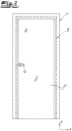
- the Fig. 1 shows a building door with a door frame 1 and a door leaf 2.
- the outside of the building door, the door frame 1 and the door leaf 2 is the side in which the door leaf 2 swings open.
- the door leaf 2 is therefore Fig. 1 from the drawing plane towards the viewer.
- the door leaf 2 In the illustrated closed position, the door leaf 2 extends along a vertical direction z and along the width of the door leaf 2 along a first horizontal direction x.
- a second horizontal direction y runs in the direction of the thickness of the door leaf 2 with respect to the illustrated closed position.
- the door leaf 2 rests against a step section 3 of a reveal 4 of the door frame 1 via a seal (not shown).
- the door leaf 2 is pivotally connected to the door frame 1 with two hinges 5, although the hinges 5 are concealed when the door leaf 2 is closed and are therefore only indicated.
- the hinges 5 do not extend beyond the width of the step section 3 along the first horizontal direction x. Even if the hinges 5 are visible in a transparent door leaf 2, this results in optical integration into the door frame 1.
- the Fig. 2 shows the arrangement according to the Fig. 1 from the opposite side, i.e. with a top view of the inside of the door leaf 2 and thus of the entire building door. Only the door frame 1, the door leaf 2 and a handle 6 on the lock side of the door leaf 2 are then visible.
- the door frame 1 therefore comprises the reveal 4, which extends up to a rebate step 7 along the second horizontal direction y.
- the passage width of the door frame 1 is determined by a reveal surface 8 of the reveal 4, whereby the door frame 1 widens in the area of the rebate step 7 with the step section 3 and whereby finally a boundary surface 9 of the reveal 4 runs parallel to the reveal surface 8 and borders laterally on the door leaf 2 in the closed position shown.
- the door leaf 2 usually rests against the shoulder section 3 via a seal (not shown), for which purpose the latter is provided with a sealing groove.
- a mirror section 10 adjoins the boundary surface 9 at a right angle, with the mirror section 10 running plane-parallel to the outside of the door leaf 2, resulting in a particularly homogeneous and uniform appearance.
- the mirror section 10 can also be flush with an adjacent wall surface (not shown).
- the two door hinges 5 are invisible or at least almost invisible when viewed from the outside.
- the Fig. 3B shows the door leaf 2 in an opening position, whereby the Door hinge 5 is visible.
- the door hinge 5 comprises a frame body 11 and a leaf body 12, both of which - as explained further below - are designed in several parts.
- the leaf body 12 engages with a hinge portion 13 in a receiving space 14 of the frame body 11, wherein the leaf body 12 is pivotally connected to the frame body 11 at the end of the hinge portion 13 and wherein a corresponding pivot axis 5 is located within the recess A of the door frame 1.
- the recess A in the embodiment is located approximately halfway in the reveal surface 8 and in the boundary surface 9.
- the pivot axis S is then arranged as far as possible in the direction of the outside in the embodiment shown and thus in the area of the boundary surface 9 with respect to the second horizontal direction y (see also below Fig. 5 ).
- the Fig. 4 shows the section according to the Fig. 3A in a view of the inside of the door leaf 2 and door frame 1. It can be seen that in the closed position shown, the leaf body 12 is completely inserted into the recess A along the first horizontal direction x and is thus barely visible. In the closed position, the entire arrangement of the door hinges 5 is therefore exceptionally inconspicuous and restrained.
- the Fig. 5 shows a part of the building door in a cross-section.
- the fastening of the leaf body 12 can be seen particularly clearly only on the inside of the door leaf 2, with the leaf body 12 along the first horizontal direction x does not protrude from the recess A and is approximately flush with the adjacent reveal surface 8.
- the flush arrangement of the outside of the door leaf 2 with the adjacent mirror section 10 can also be seen.
- the pivot axis S is oriented as far as possible towards the outside with respect to the recess A, so that the door leaf 2 can be swung open without jamming even with a simple hinge construction with exactly one pivot axis S. It is also advantageous that the leaf body 12 is only attached to the inside of the door leaf 2 and thus does not lead to a widening along the first horizontal direction x, which could lead to jamming during an opening movement.
- FIG. 6 and Fig. 7 Further details of the building door and the two door hinges can be found in the Fig. 6 and Fig. 7 , whereby the components of the exemplary door hinge 5 are shown and arranged in a largely identical manner. For a better recognition of details, Fig. 7 However, in the exploded view the door frame 1 and the door leaf 2 are omitted.
- the frame body 11 comprises a base body 16 and an insert 17, wherein the insert 17 accommodates screw heads of adjusting screws 18, with which the insert 17 can be positioned along the first horizontal direction x relative to the base body 16.
- the base body 16 further comprises fastening holes 19, wherein the frame body 11 is fastened to the door frame 1 with fastening screws (not shown) which extend through the fastening holes 19.
- the cover plates 15 are then provided, which for the sake of simplicity are in the Fig. 6 and 7 omitted are.
- the leaf body 12 is also designed in several parts and comprises a fastening part 20 and a separately formed hinge part 21. As described further below, this has the advantage that the fastening part 20 and the hinge part 21 can only be connected to one another when the door leaf 2 is mounted on the door frame 1, whereby a height adjustment can also be realized with a screw.
- the hinge part 21 also comprises the hinge tab section 13, wherein the corresponding holes in the insert 17 and the hinge tab section 13 are shown for the articulated connection of the sash body 12 and the frame body 11, but not the associated pivot pin.
- the fastening part 20 has a contact surface 22 with which the fastening part 20 is glued to the inside of the door leaf 2. Such a bonding can also take place in particular before the fastening part 20 is connected to the hinge part 21.
- the fastening part 20 has two connection formations 23 opposite the contact surface 22, each in the form of a projection, wherein a vertical bore 24 is provided in each connection formation 23.
- the band part 21 has, adjacent to the band flap section 13, a connecting section 25 with openings 26 which are provided for receiving the connection formations 23.
- FIG. 6 and 7 It can be seen that the openings 26 extend over a greater height than the respective associated connection formations 23, so that even after the connection of the fastening part 20 to the band part 21 by a connecting pin 27, an adjustment along the vertical direction z is still possible.
- a connecting pin (not shown) is with regard to the Fig. 6 and 7 also provided on the underside of the wing body 12.
- An adjustment can be made at the upper connection formation 23 and/or the lower connection formation 23.
- a screwing means in the form of a threaded pin can be provided, which engages in a thread in the vertical bore 24 and/or in the connecting section 25, wherein the adjustment can then be made by adjusting the threaded pin.
- Suitable embodiments are known to the person skilled in the art.
- Fig. 8 shows a vertical section in the area of the connection formations 23 with the vertical holes 24. If, for example, before mounting the door hinge 5, the connection formations 23 of the fastening part 20 are inserted into associated openings 26 on the connecting section 25 of the hinge part 21, the door leaf 2 with the fastening part 20 attached to it will sag downwards until the connection formations 23 strike the lower edge of the associated opening 26. If, for example, the vertical hole 24 of the upper connection formation 23 is equipped with an internal thread and the connecting pin 27 in the form of a threaded pin is screwed in from above, the connection formation 23 and thus the entire door leaf 2 can be raised as desired with an appropriate screw-in depth.
Landscapes
- Engineering & Computer Science (AREA)
- Mechanical Engineering (AREA)
- Civil Engineering (AREA)
- Structural Engineering (AREA)
- Wing Frames And Configurations (AREA)
- Hinges (AREA)
Description
- Die Erfindung betrifft eine Gebäudetür mit einer Türzarge, einem ungefälzten Türflügel, insbesondere aus Glas, und zumindest einem Türband, mit welchem der Türflügel schwenkbeweglich mit der Türzarge verbunden ist, wobei sich der Türflügel in einer Schließstellung in einer vertikalen Richtung und entlang einer Türblattbreite in einer ersten horizontalen Richtung erstreckt, wobei die Türzarge an einer Bandseite eine Laibung mit einer Laibungsfläche, einer Falzstufe und einer seitlich an den Türflügel in der Schließstellung angrenzenden Begrenzungsfläche aufweist, wobei an der Falzstufe ein einer Innenseite des Türflügels zugewandter Absatzabschnitt die Laibungsfläche und die Begrenzungsfläche miteinander verbindet, wobei ein Zargenkörper des Türbandes in eine Ausnehmung der Laibung eingesetzt ist und wobei ein Teil eines Flügelkörpers des Türbandes in der Schließstellung innerhalb der Ausnehmung angeordnet ist.
- Mit dem ungefälzten Türflügel ist die Gebäudetür besonders als Innentür und insbesondere Zimmertür geeignet. Der ungefälzte Flügel kann auf besonders einfache Weise aus einem plattenförmigen Material gebildet sein, wobei Glas als bevorzugtes Material als Platte oder Scheibe mit einer üblicherweise einheitlichen oder im Wesentlichen einheitlichen Dicke bereitgestellt werden kann. Die Dicke des Türflügels kann bei einer Ausgestaltung aus Glas beispielsweise zwischen 6 mm und 20 mm betragen, wobei jedoch auch andere plattenförmige Materialien in Betracht kommen. Gebäudetüren mit einem ungefälzten Türflügel und insbesondere mit einem Türflügel aus Glas mit den eingangs beschriebenen Merkmalen sind aus
DE 10 2017 100 252 B3 ,DE 10 2017 100 254 B3 ,DE 10 2017 100 270 B3 undDE 20 2017 100 143 U1 bekannt. - Bei der in diesem Stand der Technik beschriebenen Gebäudetür wird der Türflügel aus Glas auf besonders einfache Weise an seinem Rand von einem Flügelkörper des Türbandes geklemmt, wozu der Flügelkörper den Rand des Türflügels U-förmig umgreift und sich somit an einer Außenseite, einer Innenseite sowie dem zugeordneten Rand des Türflügels erstreckt. Die Innenseite des Türflügels ist dabei in der Schließstellung dem Absatzabschnitt zugewandt und liegt üblicherweise auch über eine Dichtung daran an.
- Ausgehend von der Schließstellung kann der Türflügel in Richtung seiner Außenseite aufgeschwenkt werden. In dem Stand der Technik ist dabei auch beschrieben, dass der Türflügel mit einer Stirnseite der Türzarge in etwa flächenbündig ist oder gegenüber der Stirnseite zurückspringt (
Fig. 3 vonDE 10 2017 100 254 B3 ). Es ergibt sich so ein hochwertiges Erscheinungsbild, bei dem die Türbänder auch aufgrund ihrer kompakten Bauweise relativ unauffällig in das Gesamtbild integriert sind. - In diesem Zusammenhang ist zu bemerken, dass die Gebäudetür für eine gleichmäßige Abstützung des Türflügels an der Türzarge üblicherweise zwei Türbänder aufweist, die vorzugsweise gleich ausgestaltet sind. Somit ist es sowohl hinsichtlich des Standes der Technik als auch hinsichtlich der Erfindung selbst ausreichend, die Struktur und Funktionsweise eines der Türbänder zu erläutern.
- Um eine kompakte Anordnung des Türbandes zu ermöglichen, ist in der Laibung die Ausnehmung gebildet. Die Ausnehmung befindet sich in der Laibungsfläche sowie in der Begrenzungsfläche, die mit einem Versatz zueinander parallel ausgerichtet sind. In der Schließstellung taucht der Flügelkörper teilweise in die Ausnehmung ein. Dies führt dazu, dass in der Schließstellung bei einer Betrachtung der Innenseite des Türflügels das Türband nur zu einem Teil sichtbar ist.
- Weitere Gebäudetüren mit den Merkmalen des Oberbegriffes des Anspruch 1 sind aus
EP 3 683 388 A1 undUS 2003/0088943 A1 bekannt, wobei die Türbänder verdeckt in die Türzarge und eine Schmalseite des Türflügels eingesetzt sind. Der Zargenkörper und der Flügelkörper sind über eine fünfachsige Gelenkarmanordnung miteinander verbunden. - Die
FR 2 324 839 A1 - Gemäß der
EP 1 108 840 A2 ist es bekannt, Türbänder durch ein Verkleben ausschließlich an einer Seite eines Türflügels zu befestigen. - Auch wenn gemäß dem Stand der Technik eine Gebäudetür mit einem Türflügel aus Glas bereitgestellt werden kann, die sich durch ein besonders ansprechendes, minimalistisches und hochwertiges Design auszeichnet, besteht das Bedürfnis, das optische Erscheinungsbild bei einer konstruktiv möglichst einfachen Ausgestaltung weiter zu verbessern.
- Gegenstand der Erfindung und Lösung der Aufgabe ist eine Gebäudetür gemäß Patentanspruch 1.
- Entsprechend erstreckt sich der Flügelkörper nicht an der Außenseite des Türflügels. Der Türflügel bildet also auch im Bereich des zumindest einen Türbandes an der Außenseite eine durchgehende nicht unterbrochene und auch nicht abgedeckte Fläche, was zu einem besonders hochwertigen Erscheinungsbild der Gebäudetür beiträgt.
- Der Flügelkörper ist gemäß der Erfindung ausschließlich an der Innenseite des Türflügels angeordnet und befestigt. So ergibt sich auch an der entsprechenden Seite des Türflügels ein gleichmäßiger oder im Wesentlichen gleichmäßiger Spalt. Außer in einem solchen schmalen Spalt zwischen dem Türflügel und der umgebenden Begrenzungsfläche oder gegebenenfalls durch den Türflügel hindurch ist der Flügelkörper bei einer Betrachtung der Außenseite des Türflügels nicht sichtbar. Insbesondere bei einer matten, undurchsichtigen und/oder farbigen Ausgestaltung des Türflügels ist das gesamte Türband bei einer Betrachtung der Außenseite des Türflügels unsichtbar oder praktisch unsichtbar. Selbst wenn der Türflügel aus einem klaren Glas gebildet ist, ist das Türband in der Schließstellung zu einem großen Teil in die Ausnehmung eingesetzt und fällt gerade bei einer farblichen Anpassung nicht oder allenfalls kaum ins Auge.
- Um den Flügelkörper wie beschrieben an der Innenseite des Türflügels und der Seitenkante des Türflügels oder besonders bevorzugt ausschließlich an der Innenseite des Türflügels zu befestigen, kann ein Verkleben erfolgen. Für den Fachmann sind hochfeste Klebstoffe verfügbar, mit denen Türflügel aus Glas oder anderen plattenförmigen Materialien sicher mit dem üblicherweise aus Metall gebildeten Flügelkörper verklebt werden können. Dabei ist zu beachten, dass das typische Gewicht des Türflügels zwischen 10 kg und 100 kg, insbesondere zwischen 15 kg und 50 kg beträgt.
- Im Rahmen der Erfindung wird auch angestrebt, dass das zumindest eine Türband der Gebäudetür auch bei einer Betrachtung der Innenseite des Türflügels in der Schließstellung besonders unauffällig und vorzugsweise nahezu unsichtbar ist.
- Gemäß einer bevorzugten Ausgestaltung der Erfindung ist in diesem Zusammenhang vorgesehen, dass der Flügelkörper in der Schließstellung entlang der ersten horizontalen Richtung weniger als 10 mm gegenüber der Laibungsfläche vorsteht und insbesondere flächenbündig mit der Laibungsfläche ist oder gegenüber der Laibungsfläche in die Ausnehmung hinein zurückspringt.
- Der Flügelkörper ist dann in der Schließstellung weitgehend oder auch vollständig entlang der ersten horizontalen Richtung in die Türzarge im Bereich der Laibungsfläche integriert.
- Die einzelnen Abschnitte und Flächen der Gebäudetür sind üblicherweise entlang von drei zueinander senkrecht stehenden Koordinaten angeordnet, zumindest wenn der Türflügel geschlossen ist. Die Gebäudetür deckt üblicherweise eine Wandöffnung ab, welche sich entlang der vertikalen Richtung und entlang der ersten horizontalen Richtung erstreckt. Die erste horizontale Richtung entspricht dabei also auch der Türblattbreite, so dass sich der Türflügel ebenfalls entlang der vertikalen Richtung und der ersten horizontalen Richtung erstreckt.
- Die Laibung verläuft dann entlang der vertikalen Richtung und im Wesentlichen entlang einer zweiten horizontalen Richtung, welche in der Schließstellung auch der Dickenrichtung des Türflügels entspricht. Konkret verlaufen die Laibungsfläche und die Begrenzungsfläche entlang der vertikalen Richtung und der ersten horizontalen Richtung, wobei dann an der Falzstufe der Absatzabschnitt im Wesentlichen entlang der vertikalen Richtung und der zweiten horizontalen Richtung verläuft.
- Dabei ist zu beachten, dass der Absatzabschnitt in der Regel nicht völlig eben ausgestaltet ist, sondern beispielsweise mit einer Dichtungsnut und einer darin eingesetzten Dichtung versehen sein kann.
- Im Rahmen der Erfindung steht die Anordnung des zumindest einen Türbandes und üblicherweise von zwei Türbändern im Vordergrund, mit denen der Türflügel an der Türzarge schwenkbeweglich befestigt ist. Deshalb wird die Laibung auch im Zusammenhang mit der Bandseite des Türflügels und der Türzarge erläutert. Üblicherweise ist die gegenüberliegende Seite der Gebäudetür, die Schlossseite der Gebäudetür, in entsprechender oder ähnlicher Weise ausgeführt. Das gleiche gilt für einen Sturzbereich oberhalb des Türflügels.
- Wie bereits zuvor erläutert, ist der Türflügel vorzugsweise aus Glas gebildet, wobei die typische Dicke in einem Bereich zwischen 6 mm und 20 mm liegt. Wenn das zumindest eine Türband in der beschriebenen Weise auf den Türflügel aufgeklebt ist, müssen dort keine Öffnungen, Einschnitte oder dergleichen in dem Glas vorgesehen werden. Um an der Schlossseite eine Drückergarnitur, einen Handgriff oder dergleichen anzuordnen, kann dort eine Durchbrechung des Türflügels vorgesehen sein. Grundsätzlich sind jedoch auch Betätigungsmittel bekannt, die lediglich auf den Türflügel aufgesetzt sind. Einfache Griffe können beispielsweise aufgeklebt werden. Sofern eine mechanische Betätigung vorgesehen ist, so kann diese auch magnetisch durch den Türflügel hindurch erfolgen.
- Um eine möglichst einfache Ausgestaltung der Gebäudetür zu ermöglichen, ist im Rahmen der Erfindung vorgesehen, dass der Zargenkörper und der Flügelkörper über genau eine Schwenkachse verbunden sind, welche innerhalb der Ausnehmung angeordnet ist.
- Besonders bevorzugt befindet sich die Schwenkachse dann in einem Bereich der Ausnehmung, der in Richtung der Außenseite des Türflügels in seiner Schließstellung verschoben ist. Entlang der zweiten horizontalen Richtung, also der Dickenrichtung des Türflügels kann sich die Schwenkachse beispielsweise auf Höhe des Türflügels selbst bzw. innerhalb der Dicke des Türflügels befinden. Durch eine in Richtung der Außenseite versetzte Anordnung der Schwenkachse kann erreicht werden, dass der Türflügel ohne ein Klemmen trotz der kompakten Bauweise des Türbandes aufgeschwenkt werden kann.
- Dabei ist auch die Befestigung des Flügelkörpers an der Innenseite des Türflügels und vorzugsweise ausschließlich an der Innenseite des Türflügels von Vorteil, weil zumindest der unmittelbar an den Türflügel angeschlossene Bereich des Flügelkörpers nicht seitlich vorsteht und bei einem Verschwenken auch nicht verklemmen kann.
- Gemäß der üblichen Bauform der Türzarge kann an die Laibung an der Außenseite der Tür ein Spiegelabschnitt anschließen, welcher parallel zu dem Türflügel verläuft und somit entlang der vertikalen Richtung und der ersten horizontalen Richtung ausgerichtet ist. Zwischen dem Spiegelabschnitt und der Begrenzungsfläche ist dann in üblicher Weise ein rechter Winkel gebildet. In diesem Zusammenhang ist gemäß einer bevorzugten Ausgestaltung der Erfindung vorgesehen, dass der Spiegelabschnitt zu der Außenseite des Türflügels flächenbündig oder im Wesentlichen flächenbündig ist. Es ergibt sich dann trotz der Anordnung der Gebäudetür der Eindruck einer durchgehenden Fläche. In diesem Zusammenhang ist es auch von besonderem Vorteil, wenn der Spiegelabschnitt flächenbündig oder im Wesentlichen flächenbündig zu der angrenzenden Wandfläche ist.
- Gemäß einem weiteren Aspekt der Erfindung ist vorgesehen, dass der Zargenkörper und/oder der Flügelkörper mehrteilig ausgestaltet ist bzw. sind. Eine mehrteilige Ausgestaltung von Flügelkörper und Zargenkörper kann zweckmäßig sein, um diese Komponenten leicht herstellen zu können, eine Verstellung zu ermöglichen oder auch die Montage zu erleichtern, wie dies insbesondere im Zusammenhang mit dem Flügelkörper nachfolgend weiter erläutert wird.
- So ist gemäß einer bevorzugten Ausgestaltung der Erfindung vorgesehen, dass der Flügelkörper ein an dem Türflügel befestigtes Befestigungsteil und ein separates Bandteil mit einem Bandlappenabschnitt aufweist, wobei besonders bevorzugt das Befestigungsteil und das Bandteil gegeneinander verstellbar und insbesondere in vertikaler Richtung verstellbar sind.
- Zusätzlich oder alternativ kann auch der Zargenkörper mehrteilig ausgeführt sein, um beispielsweise eine Verstellung in zumindest eine der beiden horizontalen Richtungen zu ermöglichen.
- So ist gemäß einer möglichen Ausgestaltung der Gebäudetür vorgesehen, dass der mehrteilige Zargenkörper einen Grundkörper und einen Einsatz umfasst, wobei der Grundkörper und der Einsatz gegeneinander verstellbar sind. Beispielsweise können der Grundkörper und der Einsatz durch entsprechende Freiräume und Stellmittel wie Schrauben entlang der ersten horizontalen Richtung positionierbar sein, so dass dann eine seitliche Verstellung des Türflügels innerhalb der Türzarge möglich ist. Wenn bei einer üblichen Ausgestaltung zwei Türbänder vorgesehen sind, kann durch eine Betätigung entsprechender Einstellmittel an beiden Türbändern der Türflügel seitlich entlang der ersten horizontalen Richtung verschoben werden. Bei einer ungleichen Einstellung kann dann ein Durchhängen des Türflügels bzw. eine Verkippung des Türflügels ausgeglichen werden.
- Ein Türband, welches in besonderem Maße für die zuvor beschriebene Gebäudetür geeignet ist, wird nachfolgend detaillierte erläutert.
- Das Türband umfasst wie bereits zuvor beschrieben den Zargenkörper und den Flügelkörper, wobei ein Bandlappenabschnitt des Flügelkörpers in einen Aufnahmeraum des Zargenkörpers eingreift und an seinem Ende an einer Schwenkachse mit dem Zargenkörper verbunden ist. Der Flügelkörper weist eine Anlagefläche zur Verbindung und insbesondere für ein Verkleben mit einer Innenseite des Türflügels auf, wobei sich die Anlagefläche entlang einer Höhe zwischen 60 mm und 200 mm, insbesondere zwischen 100 mm und 150 mm und senkrecht dazu über eine Breite zwischen 5 mm und 20 mm, insbesondere zwischen 6 mm und 12 mm erstreckt. Bei der zuvor beschriebenen Gebäudetür bezieht sich die Höhe auf die vertikale Richtung und die Breite bezogen auf die Schließstellung auf die erste horizontale Richtung.
- Bei dem Türband ist somit eine Anlagefläche vorgesehen, welche äußerst schmal ausgeführt ist. Eine ausreichende Gesamtfläche wird dabei durch eine vergleichsweise große Höhe bereitgestellt. Es ist damit möglich, den Flügelkörper besonders schmal auszuführen, so dass dieser in der Schließstellung im Wesentlichen oder vollständig verdeckt innerhalb der Türzarge bzw. der daran gebildeten Ausnehmung angeordnet ist.
- Gemäß einer Weiterbildung ist vorgesehen, dass der Flügelkörper mehrteilig mit einem die Anlagefläche aufweisenden Befestigungsteil und einem separaten, den Bandlappenabschnitt aufweisenden Bandteil gebildet ist, wobei das Befestigungsteil gegenüberliegend der Anlagefläche zumindest eine Anschlussausformung zur Kopplung mit dem Verbindungsabschnitt des Bandteils aufweist. Beispielsweise kann die Anschlussausformung als eine Art Vorsprung ausgeführt sein, wobei der Verbindungsabschnitt zumindest eine Öffnung für die zumindest eine Anschlussausformung aufweist. Durch eine derartige Zweiteilung sind mehrere Vorteile zu erzielen. Einerseits ist bei einer entsprechenden Detailausgestaltung eine Verstellung zwischen dem Befestigungsteil und dem Bandteil möglich, wobei gerade eine Verstellung entlang der Höhe, d.h. der vertikalen Richtung sehr einfach realisiert werden kann. Darüber hinaus kann die zweiteilige Ausgestaltung auch hinsichtlich einer Montage von Vorteil sein.
- Dabei ist zu beachten, dass gerade ein Verkleben des Flügelkörpers mit dem vorzugsweise aus Glas gebildeten Türflügel besonders genau erfolgen muss, weil je nach Klebstoff eine Korrektur nicht oder nur mit einem erheblichen Aufwand möglich ist. Auch ist die Montage von Türbändern schwierig, wenn diese bereits mit dem Türflügel verklebt sind. Vor diesem Hintergrund ist gemäß einer bevorzugten Ausgestaltung vorgesehen, dass das Befestigungsteil und das Bandteil zunächst separat gebildet sind und erst bei der Montage miteinander verbunden werden. Das Befestigungsteil kann dann zunächst präzise an der entsprechenden Stelle auf dem Türflügel platziert und insbesondere verklebt werden, wobei dann das Befestigungsteil - vorzugsweise bereits mit den weiteren Bestandteilen des Türbandes verbunden - montiert werden kann, wozu der Zargenkörper in den Aufnahmeraum der Türzarge eingesetzt wird.
- Gemäß einer Weiterbildung ist dann vorgesehen, dass das Befestigungsteil und das Bandteil mit geeigneten Verbindungsmitteln, beispielsweise zumindest einem Verbindungstift verbunden sind. Abgesehen von einer optionalen Verstellung des Bandteils und des Befestigungsteils insbesondere entlang der vertikalen Richtung erfolgt eine solche Verbindung üblicherweise unbeweglich, wobei eine Verbindung durch einen Verbindungstift oder dergleichen grundsätzlich auch reversibel ausgeführt sein kann.
- Wie bereits zuvor erläutert, ist gemäß einer bevorzugten Ausgestaltung eine Verstellbarkeit des Befestigungsteils und des Bandteils entlang der Höhe vorgesehen, wobei der Stellweg entlang der Höhe, beispielsweise zwischen 3 mm und 14 mm, insbesondere zwischen 6 mm und 11 mm betragen kann.
- Für die Höhenverstellung kann insbesondere ein Schraubmittel vorgesehen sein, wobei je nach Ausführungsform Gewindestifte, Schrauben, Stellspindeln oder dergleichen in Betracht kommen.
- Die Erfindung wird im Folgenden anhand einer lediglich ein Ausführungsbeispiel darstellenden Zeichnung erläutert Es zeigen:
- Fig. 1
- eine Gebäudetür in einer Ansicht auf eine Außenseite,
- Fig. 2
- die Gebäudetür gemäß der
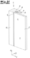
Fig. 1 in einer Ansicht auf eine Innenseite, - Fig. 3A
- einen Ausschnitt der Gebäudetür in einer perspektivischen Ansicht auf die Außenseite bei einem geschlossenen Türflügel,
- Fig. 3B
- der Ausschnitt gemäß der
Fig. 3A bei einem geöffneten Türflügel, - Fig. 4
- der Ausschnitt gemäß der
Fig. 3A bei einer Ansicht auf eine Innenseite der Gebäudetür, - Fig. 5
- einen Ausschnitt der Gebäudetür in einem Horizontalschnitt,
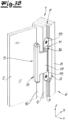
- Fig. 6
- der Ausschnitt gemäß der
Fig. 3A mit einer Türzarge, einem Türflügel sowie einem Türband in einer Explosionsdarstellung, - Fig. 7
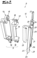
- lediglich das Türband in einer Explosionsdarstellung,
- Fig. 8
- einen Schnitt durch einen Zargenkörper des Türbandes.
- Die
Fig. 1 zeigt eine Gebäudetür mit einer Türzarge 1 und einem Türflügel 2. Als Außenseite der Gebäudetür, der Türzarge 1 und des Türflügels 2 wird die Seite bezeichnet, in welche der Türflügel 2 aufschwingt. Der Türflügel 2 ist also hinsichtlich derFig. 1 aus der Zeichnungsebene in Richtung des Betrachters zu öffnen. - In der dargestellten Schließstellung erstreckt sich der Türflügel 2 entlang einer vertikalen Richtung z und entlang der Breite des Türflügels 2 entlang einer ersten horizontalen Richtung x. Eine zweite horizontale Richtung y verläuft in Richtung der Dicke des Türflügels 2 in Bezug auf die dargestellte Schließstellung.
- Wie sich auch aus den weiteren Zeichnungen ergibt, liegt der Türflügel 2 an einem Absatzabschnitt 3 einer Laibung 4 der Türzarge 1 über eine nicht dargestellte Dichtung an. Der Türflügel 2 ist mit zwei Türbändern 5 schwenkbeweglich mit der Türzarge 1 verbunden, wobei jedoch die Türbänder 5 bei geschlossenem Türflügel 2 verdeckt und deshalb lediglich angedeutet sind. In diesem Zusammenhang ist auch zu erkennen, dass die Türbänder 5 sich entlang der ersten horizontalen Richtung x nicht über die Breite des Absatzabschnittes 3 hinaus erstrecken. Selbst wenn dann die Türbänder 5 bei einem durchsichtigen Türflügel 2 sichtbar sind, so ergibt sich eine optische Integration in die Türzarge 1.
- Die
Fig. 2 zeigt die Anordnung gemäß derFig. 1 von der gegenüberliegenden Seite, also mit einer Draufsicht auf eine Innenseite des Türflügels 2 und somit der gesamten Gebäudetür. Sichtbar sind dann lediglich die Türzarge 1, der Türflügel 2 sowie ein Griff 6 an einer Schlossseite des Türflügels 2. - Anhand der
Figur 3A ist die Form der Türzarge 1 besser zu erkennen. Die Türzarge 1 umfasst demnach die Laibung 4, welche sich bis auf eine Falzstufe 7 entlang der zweiten horizontalen Richtung y erstreckt. Die Durchgangsbreite der Türzarge 1 wird von einer Laibungsfläche 8 der Laibung 4 bestimmt, wobei sich die Türzarge 1 im Bereich der Falzstufe 7 mit dem Absatzabschnitt 3 erweitert und wobei schließlich eine Begrenzungsfläche 9 der Laibung 4 parallel zur Laibungsfläche 8 verläuft und seitlich an den Türflügel 2 in der dargestellten Schließstellung angrenzt. - Wie bereits zuvor erläutert, liegt der Türflügel 2 üblicherweise über eine nicht dargestellte Dichtung an dem Absatzabschnitt 3 an, wozu dieser mit einer Dichtungsnut versehen ist.
- An der Außenseite der Türzarge 1 schließt über einen rechten Winkel ein Spiegelabschnitt 10 an die Begrenzungsfläche 9 an, wobei der Spiegelabschnitt 10 planparallel zu der Außenseite des Türflügels 2 verläuft, so dass sich ein besonders homogenes und einheitliches Erscheinungsbild ergibt. Insbesondere kann der Spiegelabschnitt 10 auch flächenbündig mit einer nicht dargestellten angrenzenden Wandfläche sein.
- Wie sich auch aus der
Figur 3A ergibt, sind die beiden Türbänder 5 von der Außenseite betrachtet unsichtbar oder zumindest nahezu unsichtbar. - Die
Fig. 3B zeigt den Türflügel 2 in einer Öffnungsposition, wobei dann das Türband 5 sichtbar ist. Das Türband 5 umfasst einen Zargenkörper 11 und einen Flügelkörper 12, welche beide - wie nachfolgend weiter erläutert - mehrteilig ausgeführt sind. Der Flügelkörper 12 greift mit einem Bandlappenabschnitt 13 in einen Aufnahmeraum 14 des Zargenkörpers 11 ein, wobei der Flügelkörper 12 am Ende des Bandlappenabschnittes 13 schwenkbeweglich mit dem Zargenkörper 11 verbunden ist und wobei sich eine entsprechende Schwenkachse 5 innerhalb der Ausnehmung Ader Türzarge 1 befindet. - Aus der
Fig. 3B ist auch zu erkennen, dass die Ausnehmung A sich in dem Ausführungsbeispiel etwa zur Hälfte in der Laibungsfläche 8 sowie in der Begrenzungsfläche 9 befindet. Die Schwenkachse S ist dann in dem dargestellten Ausführungsbeispiel möglichst weit in Richtung der Außenseite und damit bezüglich der zweiten horizontalen Richtung y im Bereich der Begrenzungsfläche 9 angeordnet (siehe hierzu auch nachfolgendFig. 5 ). - In der
Fig. 3B sind an dem Zargenkörper 11 auch Abdeckplatten 15 angeordnet, welche in den nachfolgenden Abbildungen zur Vereinfachung teils weggelassen sind. - Die
Fig. 4 zeigt den Ausschnitt gemäß derFig. 3A in einer Ansicht auf die Innenseite von Türflügel 2 und Türzarge 1. Es ist zu erkennen, dass in der dargestellten Schließstellung der Flügelkörper 12 entlang der ersten horizontalen Richtung x vollständig in die Ausnehmung A eingesetzt und somit kaum sichtbar ist. In der Schließstellung ist die gesamte Anordnung der Türbänder 5 also außergewöhnlich unauffällig und zurückhaltend. - Die
Fig. 5 zeigt einen Teil der Gebäudetür in einem Querschnitt. Besonders deutlich ist die Befestigung des Flügelkörpers 12 lediglich an der Innenseite des Türflügels 2 zu erkennen, wobei der Flügelkörper 12 entlang der ersten horizontalen Richtung x nicht aus der Ausnehmung A vorsteht und mit der angrenzenden Laibungsfläche 8 in etwa flächenbündig ist. Auch die flächenbündige Anordnung der Außenseite des Türflügels 2 mit dem angrenzenden Spiegelabschnitt 10 ist zu erkennen. - Die Schwenkachse S ist hinsichtlich der Ausnehmung A soweit wie möglich in Richtung der Außenseite orientiert, so dass der Türflügel 2 auch bei einer einfachen Bandkonstruktion mit genau einer Schwenkachse S ohne ein Klemmen aufgeschwungen werden kann. Dabei ist auch von Vorteil, dass der Flügelkörper 12 ausschließlich an der Innenseite des Türflügels 2 befestigt ist und somit nicht zu einer Verbreiterung entlang der ersten horizontalen Richtung x führt, welche bei einer Öffnungsbewegung zu einem Klemmen führen könnte.
- Weitere Details der Gebäudetür sowie der beiden Türbänder ergeben sich aus der
Fig. 6 undFig. 7 , wobei die Komponenten des exemplarisch dargestellten Türbandes 5 weitgehend gleich dargestellt und angeordnet sind. Für eine bessere Erkennbarkeit von Details sind in derFig. 7 jedoch bei der Explosionsdarstellung die Türzarge 1 und der Türflügel 2 weggelassen. - Gemäß der
Fig. 6 und7 umfasst der Zargenkörper 11 einen Grundkörper 16 und einen Einsatz 17, wobei der Einsatz 17 Schraubenköpfe von Stellschrauben 18 aufnimmt, mit denen der Einsatz 17 entlang der ersten horizontalen Richtung x gegenüber dem Grundkörper 16 positioniert werden kann. Der Grundkörper 16 weist des Weiteren Befestigungsbohrungen 19 auf, wobei der Zargenkörper 11 mit nicht dargestellten Befestigungsschrauben, welche sich durch die Befestigungsbohrungen 19 hindurch erstrecken, an der Türzarge 1 befestigt ist. Aus optischen Gründen sind dann die Abdeckplatten 15 vorgesehen, welche der Einfachheit halber in denFig. 6 und7 weggelassen sind. - Auch der Flügelkörper 12 ist mehrteilig ausgeführt und umfasst ein Befestigungsteil 20 und ein separat gebildetes Bandteil 21. Wie nachfolgend weiter beschrieben, ergibt sich der Vorteil, dass das Befestigungsteil 20 und das Bandteil 21 erst bei der Montage des Türflügels 2 an der Türzarge 1 miteinander verbunden werden können, wobei auch eine Höhenverstellung mit einem Schraubmittel realisiert werden kann.
- Wie in den
Fig. 6 und7 zu erkennen ist, umfasst das Bandteil 21 auch den Bandlappenabschnitt 13, wobei für die gelenkige Verbindung von dem Flügelkörper 12 und dem Zargenkörper 11 die entsprechenden Bohrungen in dem Einsatz 17 sowie dem Bandlappenabschnitt 13, jedoch nicht der zugeordnete Schwenkstift dargestellt sind. - Das Befestigungsteil 20 weist eine Anlagefläche 22 auf, mit welcher das Befestigungsteil 20 auf die Innenseite des Türflügels 2 geklebt ist. Eine entsprechende Verklebung kann insbesondere auch erfolgen, bevor das Befestigungsteil 20 mit dem Bandteil 21 verbunden wird.
- Für die Verbindung weist das Befestigungsteil 20 gegenüberliegend der Anlagefläche 22 zwei Anschlussausformungen 23 in Form jeweils eines Vorsprunges auf, wobei in jeder Anschlussausformung 23 eine Vertikalbohrung 24 vorgesehen ist.
- Das Bandteil 21 weist anschließend an den Bandlappenabschnitt 13 einen Verbindungsabschnitt 25 mit Öffnungen 26 auf, welche für eine Aufnahme der Anschlussausformungen 23 vorgesehen sind.
- Bereits in den
Fig. 6 und7 ist zu erkennen, dass die Öffnungen 26 sich über eine größere Höhe als die jeweils zugeordneten Anschlussausformungen 23 erstrecken, so dass auch nach der Verbindung des Befestigungsteils 20 mit dem Bandteil 21 durch einen Verbindungstift 27 noch eine Verstellung entlang der vertikalen Richtung z möglich ist. Ein nicht dargestellter Verbindungstift ist hinsichtlich derFig. 6 und7 auch an der Unterseite des Flügelkörpers 12 vorgesehen. - Eine Verstellung kann dabei an der oberen Anschlussausformung 23 und/oder der unteren Anschlussausformung 23 erfolgen. Es kann beispielsweise ein Schraubmittel in Form eines Gewindestifts vorgesehen sein, der in der Vertikalbohrung 24 und/oder in dem Verbindungabschnitt 25 in ein Gewinde eingreift, wobei dann durch ein Verstellen des Gewindestiftes die Verstellung erfolgen kann. Geeignete Ausführungsformen sind dem Fachmann bekannt.
- Die beschriebene Verstellbarkeit ergibt sich auch aus der
Fig. 8 , welche einen Vertikalschnitt im Bereich der Anschlussausformungen 23 mit den Vertikalbohrungen 24 zeigt. Wenn beispielsweise vor der Montage des Türbandes 5 die Anschlussausformungen 23 des Befestigungsteils 20 in zugeordneten Öffnungen 26 an dem Verbindungabschnitt 25 des Bandteils 21 eingesetzt werden, so wird der Türflügel 2 mit dem daran festgelegten Befestigungsteil 20 nach unten absacken, bis die Anschlussausformungen 23 an dem unteren Rand der zugeordneten Öffnung 26 anschlagen. Wenn dann beispielsweise die Vertikalbohrung 24 der oberen Anschlussausformung 23 mit einem Innengewinde ausgestattet ist und von oben der Verbindungstift 27 in Form eines Gewindestiftes eingeschraubt wird, kann bei einer entsprechenden Einschraubtiefe die Anschlussausformung 23 und somit der gesamte Türflügel 2 in gewünschter Weise angehoben werden.
Claims (8)
- Gebäudetür mit einer Türzarge (1), einem ungefälzten Türflügel (2) und zumindest einem Türband (5), mit welchem der Türflügel (2) schwenkbeweglich mit der Türzarge (1) verbunden ist, wobei sich der Türflügel (2) in einer Schließstellung in einer vertikalen Richtung (z) und entlang einer Türblattbreite in einer ersten horizontalen Richtung (x) erstreckt, wobei die Türzarge (1) an einer Bandseite eine Laibung (4) mit einer Laibungsfläche (8), einer Falzstufe (7) und einer seitlich an den Türflügel (2) in der Schließstellung angrenzenden Begrenzungsfläche (9) aufweist, wobei an der Falzstufe (7) ein einer Innenseite des Türflügels (2) zugewandter Absatzabschnitt (3) die Laibungsfläche (8) und Begrenzungsfläche (9) miteinander verbindet, wobei ein Zargenkörper (11) des Türbandes (5) in eine Ausnehmung (A) der Laibung (4) eingesetzt ist und wobei ein Teil eines Flügelkörpers (12) des Türbandes (5) in der Schließstellung innerhalb der Ausnehmung (A) angeordnet ist, dadurch gekennzeichnet, dass der Flügelkörper (12) ausschließlich an der Innenseite des Türflügels (2) angeordnet und befestigt ist und dass der Zargenkörper (11) und der Flügelkörper (12) über genau eine Schwenkachse (S) verbunden sind, welche innerhalb der Ausnehmung (A) angeordnet ist.
- Gebäudetür nach Anspruch 1, dadurch gekennzeichnet, dass der Flügelkörper (12) mit dem Türflügel (2) verklebt ist.
- Gebäudetür nach Anspruch 1 oder 2, dadurch gekennzeichnet, dass der Flügelkörper (12) in der Schließstellung entlang der ersten horizontalen Richtung (x) weniger als 10 mm gegenüber der Laibungsfläche (8) vorsteht und insbesondere flächenbündig mit der Laibungsfläche (8) ist oder gegenüber der Laibungsfläche (8) zurückspringt.
- Gebäudetür nach einem der Ansprüche 1 bis 3, dadurch gekennzeichnet, dass der Türflügel (2) aus Glas gebildet ist.
- Gebäudetür nach einem der Ansprüche 1 bis 4, dadurch gekennzeichnet, dass die Türzarge (1) einen an die Laibung (4) anschließenden Spiegelabschnitt (10) aufweist, welcher in der Schließstellung zu einer Außenseite des Türflügels (2) flächenbündig oder im Wesentlichen flächenbündig ist.
- Gebäudetür nach einem der Ansprüche 1 bis 5, dadurch gekennzeichnet, dass der Zargenkörper (11) und/oder der Flügelkörper (12) mehrteilig ausgestaltet ist/sind.
- Gebäudetür nach Anspruch 6, dadurch gekennzeichnet, dass der Flügelkörper (12) ein an dem Türflügel (2) befestigtes Befestigungsteil (20) und ein separates Bandteil (21) mit einem Bandlappenabschnitt (13) aufweist, wobei das Befestigungsteil (20) und das Bandteil (21) gegeneinander verstellbar sind.
- Gebäudetür nach Anspruch 6 oder 7, dadurch gekennzeichnet, dass der mehrteilige Zargenkörper (11) einen Grundkörper (16) und einen Einsatz (17) umfasst, welche gegeneinander verstellbar sind.
Applications Claiming Priority (1)
| Application Number | Priority Date | Filing Date | Title |
|---|---|---|---|
| DE102020122730.2A DE102020122730B3 (de) | 2020-08-31 | 2020-08-31 | Gebäudetür und Türband für eine Gebäudetür |
Publications (3)
| Publication Number | Publication Date |
|---|---|
| EP4001574A1 EP4001574A1 (de) | 2022-05-25 |
| EP4001574B1 true EP4001574B1 (de) | 2024-10-09 |
| EP4001574C0 EP4001574C0 (de) | 2024-10-09 |
Family
ID=75584237
Family Applications (1)
| Application Number | Title | Priority Date | Filing Date |
|---|---|---|---|
| EP21187713.9A Active EP4001574B1 (de) | 2020-08-31 | 2021-07-26 | Gebäudetür und türband für eine gebäudetür |
Country Status (2)
| Country | Link |
|---|---|
| EP (1) | EP4001574B1 (de) |
| DE (1) | DE102020122730B3 (de) |
Family Cites Families (11)
| Publication number | Priority date | Publication date | Assignee | Title |
|---|---|---|---|---|
| FR2324839B1 (fr) * | 1975-07-02 | 1978-02-24 | Paumellerie Electrique | Paumelle pour le montage d'une porte en verre |
| DE29516023U1 (de) * | 1995-10-10 | 1997-02-06 | Pauli + Sohn GmbH, 51545 Waldbröl | Beschlag |
| DE19945184A1 (de) * | 1999-09-21 | 2001-04-12 | Fischbach Joachim | Befestigungsvorrichtung für plattenförmige Bauteile |
| DE19960724C2 (de) * | 1999-12-16 | 2003-02-06 | Dorma Gmbh & Co Kg | Justierbarer Beschlag |
| ES2335866T3 (es) * | 2001-10-31 | 2010-04-06 | Simonswerk, Gesellschaft Mit Beschrankter Haftung | Bisagra de puerta para una disposicion oculta entre el cerco de la puerta y la hoja de la puerta. |
| DE102009052417A1 (de) * | 2008-12-02 | 2010-06-10 | Dorma Gmbh + Co. Kg | Beschlag für eine Glastür |
| DE102017100254B3 (de) * | 2017-01-09 | 2018-01-04 | Simonswerk Gmbh | Türanordnung |
| DE102017100270B3 (de) * | 2017-01-09 | 2018-01-11 | Simonswerk Gmbh | Türband sowie Zimmertür |
| DE102017100252B3 (de) * | 2017-01-09 | 2017-09-28 | Simonswerk Gmbh | Türanordnung |
| DE202017100143U1 (de) | 2017-01-12 | 2017-02-06 | Simonswerk Gmbh | Türanordnung |
| EP3683388A1 (de) * | 2019-01-15 | 2020-07-22 | Robert Peer | Scharnier |
-
2020
- 2020-08-31 DE DE102020122730.2A patent/DE102020122730B3/de active Active
-
2021
- 2021-07-26 EP EP21187713.9A patent/EP4001574B1/de active Active
Also Published As
| Publication number | Publication date |
|---|---|
| EP4001574A1 (de) | 2022-05-25 |
| EP4001574C0 (de) | 2024-10-09 |
| DE102020122730B3 (de) | 2021-05-12 |
Similar Documents
| Publication | Publication Date | Title |
|---|---|---|
| DE10021330C2 (de) | Verstellbare Scharnier-Rahmen-Anordnung | |
| DE202017100143U1 (de) | Türanordnung | |
| DE10034071B4 (de) | Einrichtung zum Verschließen einer Öffnung | |
| EP3346077B1 (de) | Türanordnung | |
| DE202014102793U1 (de) | Türblattseitiges Bandteil eines Türbandes und Anordnung hiermit | |
| EP2369109B1 (de) | Türband für gefälzte Gebäudeabschlusstüren aus Holz | |
| DE2748623A1 (de) | Beschlag fuer einen glasfluegel, insbesondere fuer eine ganzglastuer | |
| DE102005022042B3 (de) | Mehrdimensional verstellbares Türband an einem Türflügel | |
| DE29514335U1 (de) | Stahlzargen-Scharnierkonstruktion | |
| EP0600102B1 (de) | Beschlag für zwangsweise kipp- und parallel abstellbare und in der Schliessstellung bzw. der Kipp- oder Ausstellstellung verriegelbare Flügel | |
| DE102020122730B3 (de) | Gebäudetür und Türband für eine Gebäudetür | |
| DE602004007009T2 (de) | Verbessertes kippfenster mit arretiermittel | |
| EP3768931A1 (de) | Dichtungseinheit | |
| EP0887501B1 (de) | Verdeckt angeordneter Beschlag für Fenster, Türen oder dergleichen | |
| DE19944549A1 (de) | Verschwindscharnier | |
| DE102007025857A1 (de) | Gelenkband für Türen oder Fenster | |
| DE102019100388B3 (de) | Türvorrichtung mit flächenbündiger Abschlussebene sowie Wandsystem | |
| EP0674077B1 (de) | Tür | |
| EP1527245A1 (de) | Bandteil für ein band für türen, fenster und dergleichen | |
| DE4403524A1 (de) | Anordnung eines Ecklagers an einem Fenster oder einer Tür sowie für diese Anordnung bestimmtes Ecklager | |
| DE2419842B2 (de) | Schließschieber für Dreh-Kippfenster | |
| EP3985219B1 (de) | Anordnung mit einer bodendichtung für eine tür, bei der zwischen einem türblatt und einer zarge ein zwischenraum vorgesehen ist, in dem die einzige drehachse des türblatts verläuft | |
| EP1375802B1 (de) | Glastür für Brandschutzzwecke mit Türbandabdeckung | |
| EP0787873B1 (de) | Schliessleiste | |
| EP0616106B1 (de) | Fenster oder Tür mit Scharnierbeschlag |
Legal Events
| Date | Code | Title | Description |
|---|---|---|---|
| PUAI | Public reference made under article 153(3) epc to a published international application that has entered the european phase |
Free format text: ORIGINAL CODE: 0009012 |
|
| STAA | Information on the status of an ep patent application or granted ep patent |
Free format text: STATUS: THE APPLICATION HAS BEEN PUBLISHED |
|
| AK | Designated contracting states |
Kind code of ref document: A1 Designated state(s): AL AT BE BG CH CY CZ DE DK EE ES FI FR GB GR HR HU IE IS IT LI LT LU LV MC MK MT NL NO PL PT RO RS SE SI SK SM TR |
|
| STAA | Information on the status of an ep patent application or granted ep patent |
Free format text: STATUS: REQUEST FOR EXAMINATION WAS MADE |
|
| 17P | Request for examination filed |
Effective date: 20220614 |
|
| RBV | Designated contracting states (corrected) |
Designated state(s): AL AT BE BG CH CY CZ DE DK EE ES FI FR GB GR HR HU IE IS IT LI LT LU LV MC MK MT NL NO PL PT RO RS SE SI SK SM TR |
|
| GRAP | Despatch of communication of intention to grant a patent |
Free format text: ORIGINAL CODE: EPIDOSNIGR1 |
|
| STAA | Information on the status of an ep patent application or granted ep patent |
Free format text: STATUS: GRANT OF PATENT IS INTENDED |
|
| INTG | Intention to grant announced |
Effective date: 20240523 |
|
| GRAS | Grant fee paid |
Free format text: ORIGINAL CODE: EPIDOSNIGR3 |
|
| GRAA | (expected) grant |
Free format text: ORIGINAL CODE: 0009210 |
|
| STAA | Information on the status of an ep patent application or granted ep patent |
Free format text: STATUS: THE PATENT HAS BEEN GRANTED |
|
| AK | Designated contracting states |
Kind code of ref document: B1 Designated state(s): AL AT BE BG CH CY CZ DE DK EE ES FI FR GB GR HR HU IE IS IT LI LT LU LV MC MK MT NL NO PL PT RO RS SE SI SK SM TR |
|
| REG | Reference to a national code |
Ref country code: CH Ref legal event code: EP |
|
| REG | Reference to a national code |
Ref country code: DE Ref legal event code: R096 Ref document number: 502021005402 Country of ref document: DE |
|
| REG | Reference to a national code |
Ref country code: IE Ref legal event code: FG4D Free format text: LANGUAGE OF EP DOCUMENT: GERMAN |
|
| U01 | Request for unitary effect filed |
Effective date: 20241023 |
|
| U07 | Unitary effect registered |
Designated state(s): AT BE BG DE DK EE FI FR IT LT LU LV MT NL PT RO SE SI Effective date: 20241107 |
|
| PG25 | Lapsed in a contracting state [announced via postgrant information from national office to epo] |
Ref country code: HR Free format text: LAPSE BECAUSE OF FAILURE TO SUBMIT A TRANSLATION OF THE DESCRIPTION OR TO PAY THE FEE WITHIN THE PRESCRIBED TIME-LIMIT Effective date: 20241009 Ref country code: IS Free format text: LAPSE BECAUSE OF FAILURE TO SUBMIT A TRANSLATION OF THE DESCRIPTION OR TO PAY THE FEE WITHIN THE PRESCRIBED TIME-LIMIT Effective date: 20250209 |
|
| PG25 | Lapsed in a contracting state [announced via postgrant information from national office to epo] |
Ref country code: ES Free format text: LAPSE BECAUSE OF FAILURE TO SUBMIT A TRANSLATION OF THE DESCRIPTION OR TO PAY THE FEE WITHIN THE PRESCRIBED TIME-LIMIT Effective date: 20241009 |
|
| PG25 | Lapsed in a contracting state [announced via postgrant information from national office to epo] |
Ref country code: NO Free format text: LAPSE BECAUSE OF FAILURE TO SUBMIT A TRANSLATION OF THE DESCRIPTION OR TO PAY THE FEE WITHIN THE PRESCRIBED TIME-LIMIT Effective date: 20250109 |
|
| PG25 | Lapsed in a contracting state [announced via postgrant information from national office to epo] |
Ref country code: GR Free format text: LAPSE BECAUSE OF FAILURE TO SUBMIT A TRANSLATION OF THE DESCRIPTION OR TO PAY THE FEE WITHIN THE PRESCRIBED TIME-LIMIT Effective date: 20250110 |
|
| PG25 | Lapsed in a contracting state [announced via postgrant information from national office to epo] |
Ref country code: PL Free format text: LAPSE BECAUSE OF FAILURE TO SUBMIT A TRANSLATION OF THE DESCRIPTION OR TO PAY THE FEE WITHIN THE PRESCRIBED TIME-LIMIT Effective date: 20241009 |
|
| PG25 | Lapsed in a contracting state [announced via postgrant information from national office to epo] |
Ref country code: RS Free format text: LAPSE BECAUSE OF FAILURE TO SUBMIT A TRANSLATION OF THE DESCRIPTION OR TO PAY THE FEE WITHIN THE PRESCRIBED TIME-LIMIT Effective date: 20250109 |
|
| PG25 | Lapsed in a contracting state [announced via postgrant information from national office to epo] |
Ref country code: SM Free format text: LAPSE BECAUSE OF FAILURE TO SUBMIT A TRANSLATION OF THE DESCRIPTION OR TO PAY THE FEE WITHIN THE PRESCRIBED TIME-LIMIT Effective date: 20241009 |
|
| PG25 | Lapsed in a contracting state [announced via postgrant information from national office to epo] |
Ref country code: SK Free format text: LAPSE BECAUSE OF FAILURE TO SUBMIT A TRANSLATION OF THE DESCRIPTION OR TO PAY THE FEE WITHIN THE PRESCRIBED TIME-LIMIT Effective date: 20241009 |
|
| PG25 | Lapsed in a contracting state [announced via postgrant information from national office to epo] |
Ref country code: CZ Free format text: LAPSE BECAUSE OF FAILURE TO SUBMIT A TRANSLATION OF THE DESCRIPTION OR TO PAY THE FEE WITHIN THE PRESCRIBED TIME-LIMIT Effective date: 20241009 |
|
| PLBE | No opposition filed within time limit |
Free format text: ORIGINAL CODE: 0009261 |
|
| STAA | Information on the status of an ep patent application or granted ep patent |
Free format text: STATUS: NO OPPOSITION FILED WITHIN TIME LIMIT |
|
| U20 | Renewal fee for the european patent with unitary effect paid |
Year of fee payment: 5 Effective date: 20250727 |
|
| 26N | No opposition filed |
Effective date: 20250710 |
|
| REG | Reference to a national code |
Ref country code: CH Ref legal event code: H13 Free format text: ST27 STATUS EVENT CODE: U-0-0-H10-H13 (AS PROVIDED BY THE NATIONAL OFFICE) Effective date: 20260224 |
|
| GBPC | Gb: european patent ceased through non-payment of renewal fee |
Effective date: 20250726 |
|
| PG25 | Lapsed in a contracting state [announced via postgrant information from national office to epo] |
Ref country code: GB Free format text: LAPSE BECAUSE OF NON-PAYMENT OF DUE FEES Effective date: 20250726 |
|
| PG25 | Lapsed in a contracting state [announced via postgrant information from national office to epo] |
Ref country code: CH Free format text: LAPSE BECAUSE OF NON-PAYMENT OF DUE FEES Effective date: 20250731 |