EP4001574B1 - Porte de bâtiment et charnière pour une porte de bâtiment - Google Patents
Porte de bâtiment et charnière pour une porte de bâtiment Download PDFInfo
- Publication number
- EP4001574B1 EP4001574B1 EP21187713.9A EP21187713A EP4001574B1 EP 4001574 B1 EP4001574 B1 EP 4001574B1 EP 21187713 A EP21187713 A EP 21187713A EP 4001574 B1 EP4001574 B1 EP 4001574B1
- Authority
- EP
- European Patent Office
- Prior art keywords
- door
- wing
- hinge
- building
- door leaf
- Prior art date
- Legal status (The legal status is an assumption and is not a legal conclusion. Google has not performed a legal analysis and makes no representation as to the accuracy of the status listed.)
- Active
Links
Images


Classifications
-
- E—FIXED CONSTRUCTIONS
- E05—LOCKS; KEYS; WINDOW OR DOOR FITTINGS; SAFES
- E05D—HINGES OR SUSPENSION DEVICES FOR DOORS, WINDOWS OR WINGS
- E05D5/00—Construction of single parts, e.g. the parts for attachment
- E05D5/02—Parts for attachment, e.g. flaps
- E05D5/06—Bent flaps
-
- E—FIXED CONSTRUCTIONS
- E05—LOCKS; KEYS; WINDOW OR DOOR FITTINGS; SAFES
- E05D—HINGES OR SUSPENSION DEVICES FOR DOORS, WINDOWS OR WINGS
- E05D11/00—Additional features or accessories of hinges
- E05D11/0054—Covers, e.g. for protection
-
- E—FIXED CONSTRUCTIONS
- E05—LOCKS; KEYS; WINDOW OR DOOR FITTINGS; SAFES
- E05D—HINGES OR SUSPENSION DEVICES FOR DOORS, WINDOWS OR WINGS
- E05D7/00—Hinges or pivots of special construction
- E05D7/04—Hinges adjustable relative to the wing or the frame
- E05D7/0415—Hinges adjustable relative to the wing or the frame with adjusting drive means
- E05D7/0423—Screw-and-nut mechanisms
-
- E—FIXED CONSTRUCTIONS
- E06—DOORS, WINDOWS, SHUTTERS, OR ROLLER BLINDS IN GENERAL; LADDERS
- E06B—FIXED OR MOVABLE CLOSURES FOR OPENINGS IN BUILDINGS, VEHICLES, FENCES OR LIKE ENCLOSURES IN GENERAL, e.g. DOORS, WINDOWS, BLINDS, GATES
- E06B1/00—Border constructions of openings in walls, floors, or ceilings; Frames to be rigidly mounted in such openings
- E06B1/04—Frames for doors, windows, or the like to be fixed in openings
- E06B1/52—Frames specially adapted for doors
-
- E—FIXED CONSTRUCTIONS
- E06—DOORS, WINDOWS, SHUTTERS, OR ROLLER BLINDS IN GENERAL; LADDERS
- E06B—FIXED OR MOVABLE CLOSURES FOR OPENINGS IN BUILDINGS, VEHICLES, FENCES OR LIKE ENCLOSURES IN GENERAL, e.g. DOORS, WINDOWS, BLINDS, GATES
- E06B3/00—Window sashes, door leaves, or like elements for closing wall or like openings; Layout of fixed or moving closures, e.g. windows in wall or like openings; Features of rigidly-mounted outer frames relating to the mounting of wing frames
- E06B3/02—Wings made completely of glass
-
- E—FIXED CONSTRUCTIONS
- E05—LOCKS; KEYS; WINDOW OR DOOR FITTINGS; SAFES
- E05D—HINGES OR SUSPENSION DEVICES FOR DOORS, WINDOWS OR WINGS
- E05D5/00—Construction of single parts, e.g. the parts for attachment
- E05D5/02—Parts for attachment, e.g. flaps
- E05D5/06—Bent flaps
- E05D2005/067—Bent flaps gooseneck shaped
-
- E—FIXED CONSTRUCTIONS
- E05—LOCKS; KEYS; WINDOW OR DOOR FITTINGS; SAFES
- E05D—HINGES OR SUSPENSION DEVICES FOR DOORS, WINDOWS OR WINGS
- E05D7/00—Hinges or pivots of special construction
- E05D7/04—Hinges adjustable relative to the wing or the frame
- E05D2007/0476—Pocket hinges
-
- E—FIXED CONSTRUCTIONS
- E05—LOCKS; KEYS; WINDOW OR DOOR FITTINGS; SAFES
- E05Y—INDEXING SCHEME ASSOCIATED WITH SUBCLASSES E05D AND E05F, RELATING TO CONSTRUCTION ELEMENTS, ELECTRIC CONTROL, POWER SUPPLY, POWER SIGNAL OR TRANSMISSION, USER INTERFACES, MOUNTING OR COUPLING, DETAILS, ACCESSORIES, AUXILIARY OPERATIONS NOT OTHERWISE PROVIDED FOR, APPLICATION THEREOF
- E05Y2600/00—Mounting or coupling arrangements for elements provided for in this subclass
- E05Y2600/40—Mounting location; Visibility of the elements
- E05Y2600/41—Concealed
- E05Y2600/412—Concealed in the rabbet
-
- E—FIXED CONSTRUCTIONS
- E05—LOCKS; KEYS; WINDOW OR DOOR FITTINGS; SAFES
- E05Y—INDEXING SCHEME ASSOCIATED WITH SUBCLASSES E05D AND E05F, RELATING TO CONSTRUCTION ELEMENTS, ELECTRIC CONTROL, POWER SUPPLY, POWER SIGNAL OR TRANSMISSION, USER INTERFACES, MOUNTING OR COUPLING, DETAILS, ACCESSORIES, AUXILIARY OPERATIONS NOT OTHERWISE PROVIDED FOR, APPLICATION THEREOF
- E05Y2600/00—Mounting or coupling arrangements for elements provided for in this subclass
- E05Y2600/50—Mounting methods; Positioning
- E05Y2600/52—Toolless
- E05Y2600/526—Gluing or cementing
-
- E—FIXED CONSTRUCTIONS
- E05—LOCKS; KEYS; WINDOW OR DOOR FITTINGS; SAFES
- E05Y—INDEXING SCHEME ASSOCIATED WITH SUBCLASSES E05D AND E05F, RELATING TO CONSTRUCTION ELEMENTS, ELECTRIC CONTROL, POWER SUPPLY, POWER SIGNAL OR TRANSMISSION, USER INTERFACES, MOUNTING OR COUPLING, DETAILS, ACCESSORIES, AUXILIARY OPERATIONS NOT OTHERWISE PROVIDED FOR, APPLICATION THEREOF
- E05Y2800/00—Details, accessories and auxiliary operations not otherwise provided for
- E05Y2800/67—Materials; Strength alteration thereof
- E05Y2800/672—Glass
-
- E—FIXED CONSTRUCTIONS
- E05—LOCKS; KEYS; WINDOW OR DOOR FITTINGS; SAFES
- E05Y—INDEXING SCHEME ASSOCIATED WITH SUBCLASSES E05D AND E05F, RELATING TO CONSTRUCTION ELEMENTS, ELECTRIC CONTROL, POWER SUPPLY, POWER SIGNAL OR TRANSMISSION, USER INTERFACES, MOUNTING OR COUPLING, DETAILS, ACCESSORIES, AUXILIARY OPERATIONS NOT OTHERWISE PROVIDED FOR, APPLICATION THEREOF
- E05Y2900/00—Application of doors, windows, wings or fittings thereof
- E05Y2900/10—Application of doors, windows, wings or fittings thereof for buildings or parts thereof
- E05Y2900/13—Type of wing
- E05Y2900/132—Doors
Definitions
- the invention relates to a building door with a door frame, an unrebated door leaf, in particular made of glass, and at least one door hinge with which the door leaf is pivotably connected to the door frame, wherein the door leaf extends in a vertical direction in a closed position and along a door leaf width in a first horizontal direction, wherein the door frame has a reveal on one hinge side with a reveal surface, a rebate step and a boundary surface laterally adjacent to the door leaf in the closed position, wherein a shoulder section facing an inner side of the door leaf on the rebate step connects the reveal surface and the boundary surface to one another, wherein a frame body of the door hinge is inserted into a recess in the reveal and wherein a part of a leaf body of the door hinge is arranged within the recess in the closed position.
- the building door is particularly suitable as an interior door and in particular as a room door.
- the unrebated leaf can be formed in a particularly simple manner from a plate-shaped material, with glass being the preferred material and being provided as a plate or pane with a usually uniform or essentially uniform thickness.
- the thickness of the door leaf can be between 6 mm and 20 mm for example in a glass design, although other plate-shaped materials can also be considered.
- Building doors with an unrebated door leaf and in particular with a glass door leaf with the features described at the beginning are made of DE 10 2017 100 252 B3 , DE 10 2017 100 254 B3 , DE 10 2017 100 270 B3 and DE 20 2017 100 143 U1 known.
- the glass door leaf is clamped in a particularly simple manner at its edge by a leaf body of the door hinge, whereby the leaf body surrounds the edge of the door leaf in a U-shape and thus extends on an outer side, an inner side and the associated edge of the door leaf.
- the inner side of the door leaf faces the step section and is usually also in contact with it via a seal.
- the door leaf can be swung open towards its outer side.
- the state of the art also describes that the door leaf is approximately flush with one end face of the door frame or is set back from the end face ( Fig. 3 from DE 10 2017 100 254 B3 ). This results in a high-quality appearance, in which the door hinges are integrated relatively unobtrusively into the overall picture due to their compact design.
- the building door usually has two hinges, which are preferably designed identically, to ensure uniform support of the door leaf on the door frame. It is therefore sufficient, both in terms of the state of the art and in terms of the invention itself, to explain the structure and functioning of one of the hinges.
- the recess is formed in the reveal.
- the recess is located in the reveal surface and in the boundary surface, which are aligned parallel to each other with an offset. In the closed position, the leaf body is immersed partially into the recess. This means that when the inside of the door leaf is viewed in the closed position, only part of the door hinge is visible.
- the FR 2 324 839 A1 reveals a building door with a glass door leaf. Door hinges are attached to the door leaf by clamping on both sides.
- the leaf body does not extend to the outside of the door leaf.
- the door leaf therefore forms a continuous, uninterrupted and uncovered surface in the area of at least one door hinge on the outside, which results in a particularly high-quality appearance of the building door.
- the leaf body is arranged and fastened exclusively on the inside of the door leaf. This also results in a uniform or essentially uniform gap on the corresponding side of the door leaf. Except in such a narrow gap between the door leaf and the surrounding boundary surface or possibly through the door leaf, the leaf body is not visible when looking at the outside of the door leaf. In particular, if the door leaf is matt, opaque and/or colored, the entire door hinge is invisible or practically invisible when looking at the outside of the door leaf. Even if the door leaf is made of clear glass, the door hinge is largely inserted into the recess in the closed position and is not or at most barely noticeable, especially when the color is matched.
- gluing can be carried out.
- High-strength adhesives are available to the specialist with which door leaves made of glass or other plate-shaped materials can be securely glued to the leaf body, which is usually made of metal. It should be noted that the typical weight of the door leaf is between 10 kg and 100 kg, in particular between 15 kg and 50 kg.
- the at least one door hinge of the building door is particularly inconspicuous and preferably almost invisible even when looking at the inside of the door leaf in the closed position.
- the sash body in the closed position protrudes less than 10 mm along the first horizontal direction relative to the reveal surface and in particular is flush with the reveal surface or springs back into the recess relative to the reveal surface.
- the leaf body In the closed position, the leaf body is then largely or completely integrated into the door frame in the area of the reveal surface along the first horizontal direction.
- the individual sections and surfaces of the building door are usually arranged along three mutually perpendicular coordinates, at least when the door leaf is closed.
- the building door usually covers a wall opening that extends along the vertical direction and along the first horizontal direction.
- the first horizontal direction also corresponds to the width of the door leaf, so that the door leaf also extends along the vertical direction and the first horizontal direction.
- the reveal then runs along the vertical direction and essentially along a second horizontal direction, which in the closed position also corresponds to the thickness direction of the door leaf.
- the reveal surface and the boundary surface run along the vertical direction and the first horizontal direction, with the step section then running essentially along the vertical direction and the second horizontal direction at the rebate step.
- heel section is usually not completely flat but can, for example, be provided with a sealing groove and a seal inserted therein.
- the focus is on the arrangement of at least one door hinge and usually two door hinges, with which the door leaf is pivotably attached to the door frame. Therefore, the reveal is also explained in connection with the hinge side of the door leaf and the door frame.
- the opposite side of the building door, the lock side of the building door, is usually designed in a corresponding or similar manner. The same applies to a lintel area above the door leaf.
- the door leaf is preferably made of glass, with the typical thickness being in a range between 6 mm and 20 mm. If at least one door hinge is glued to the door leaf in the manner described, no openings, cuts or the like need to be provided in the glass. In order to arrange a handle set, a handle or the like on the lock side, an opening in the door leaf can be provided there. In principle, however, actuating means are also known which are simply placed on the door leaf. Simple handles can be glued on, for example. If mechanical actuation is provided, this can also be carried out magnetically through the door leaf.
- the invention provides that the frame body and the leaf body are connected via exactly one pivot axis, which is arranged within the recess.
- the pivot axis is then particularly preferably located in an area of the recess that is shifted towards the outside of the door leaf in its closed position.
- the pivot axis can be located, for example, at the height of the door leaf itself or within the thickness of the door leaf.
- wing body is also advantageous to attach the wing body to the inside of the door wing and preferably only to the inside of the door wing, because at least the area of the wing body that is directly connected to the door wing does not protrude sideways and cannot jam when pivoted.
- a mirror section can be connected to the reveal on the outside of the door, which runs parallel to the door leaf and is thus aligned along the vertical direction and the first horizontal direction. A right angle is then formed in the usual way between the mirror section and the boundary surface.
- the mirror section is flush or essentially flush with the outside of the door leaf. This then gives the impression of a continuous surface despite the arrangement of the building door.
- the frame body and/or the sash body is or are designed in several parts.
- a multi-part design of the sash body and frame body can be useful in order to be able to manufacture these components easily, to enable adjustment or to facilitate assembly, as will be explained further below in particular in connection with the sash body.
- the leaf body has a fastening part fastened to the door leaf and a separate hinge part with a hinge flap section, wherein particularly preferably the fastening part and the hinge part are adjustable relative to one another and in particular adjustable in the vertical direction.
- the frame body can also be designed in several parts, for example to enable adjustment in at least one of the two horizontal directions.
- the multi-part frame body comprises a base body and an insert, wherein the base body and the insert are adjustable relative to one another.
- the base body and the insert can be positioned along the first horizontal direction using appropriate clearances and adjusting means such as screws, so that the door leaf can then be adjusted laterally within the door frame.
- the door leaf can be moved laterally along the first horizontal direction by operating appropriate adjusting means on both door hinges. If the adjustment is uneven, sagging of the door leaf or tilting of the door leaf can then be compensated for.
- a door hinge which is particularly suitable for the building door described above is explained in detail below.
- the door hinge comprises the frame body and the leaf body, with a hinge portion of the leaf body engaging in a receiving space of the frame body and being connected to the frame body at its end on a pivot axis.
- the leaf body has a contact surface for connection and in particular for gluing to an inner side of the door leaf, with the contact surface extending along a height of between 60 mm and 200 mm, in particular between 100 mm and 150 mm, and perpendicularly thereto over a width of between 5 mm and 20 mm, in particular between 6 mm and 12 mm.
- the height refers to the vertical direction and the width in relation to the closed position refers to the first horizontal direction.
- the door hinge is therefore provided with a contact surface that is extremely narrow. A sufficient total area is provided by a comparatively large height. This makes it possible to make the leaf body particularly narrow, so that in the closed position it is arranged essentially or completely concealed within the door frame or the recess formed therein.
- the wing body is formed in several parts with a fastening part having the contact surface and a separate band part having the hinge portion, wherein the fastening part opposite the contact surface has at least one connection formation for coupling with the connection portion of the band part.
- the connection formation can be designed as a type of projection, wherein the connecting section has at least one opening for the at least one connection formation.
- gluing the leaf body to the door leaf which is preferably made of glass, must be carried out particularly precisely because, depending on the adhesive, corrections may not be possible or may only be possible with considerable effort. It is also difficult to install door hinges if they are already glued to the door leaf.
- the fastening part and the hinge part are initially formed separately and are only connected to one another during assembly. The fastening part can then first be precisely placed and in particular glued at the appropriate point on the door leaf, whereby the fastening part - preferably already connected to the other components of the door hinge - can then be installed, for which purpose the frame body is inserted into the receiving space of the door frame.
- the fastening part and the band part are connected with suitable connecting means, for example at least one connecting pin.
- suitable connecting means for example at least one connecting pin.
- an adjustability of the fastening part and the band part along the height is provided, wherein the adjustment path along the height can be, for example, between 3 mm and 14 mm, in particular between 6 mm and 11 mm.
- a screw means can be provided for the height adjustment, whereby, depending on the design, threaded pins, screws, adjusting spindles or the like can be used.
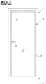
- the Fig. 1 shows a building door with a door frame 1 and a door leaf 2.
- the outside of the building door, the door frame 1 and the door leaf 2 is the side in which the door leaf 2 swings open.
- the door leaf 2 is therefore Fig. 1 from the drawing plane towards the viewer.
- the door leaf 2 In the illustrated closed position, the door leaf 2 extends along a vertical direction z and along the width of the door leaf 2 along a first horizontal direction x.
- a second horizontal direction y runs in the direction of the thickness of the door leaf 2 with respect to the illustrated closed position.
- the door leaf 2 rests against a step section 3 of a reveal 4 of the door frame 1 via a seal (not shown).
- the door leaf 2 is pivotally connected to the door frame 1 with two hinges 5, although the hinges 5 are concealed when the door leaf 2 is closed and are therefore only indicated.
- the hinges 5 do not extend beyond the width of the step section 3 along the first horizontal direction x. Even if the hinges 5 are visible in a transparent door leaf 2, this results in optical integration into the door frame 1.
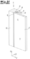
- the Fig. 2 shows the arrangement according to the Fig. 1 from the opposite side, i.e. with a top view of the inside of the door leaf 2 and thus of the entire building door. Only the door frame 1, the door leaf 2 and a handle 6 on the lock side of the door leaf 2 are then visible.
- the door frame 1 therefore comprises the reveal 4, which extends up to a rebate step 7 along the second horizontal direction y.
- the passage width of the door frame 1 is determined by a reveal surface 8 of the reveal 4, whereby the door frame 1 widens in the area of the rebate step 7 with the step section 3 and whereby finally a boundary surface 9 of the reveal 4 runs parallel to the reveal surface 8 and borders laterally on the door leaf 2 in the closed position shown.
- the door leaf 2 usually rests against the shoulder section 3 via a seal (not shown), for which purpose the latter is provided with a sealing groove.
- a mirror section 10 adjoins the boundary surface 9 at a right angle, with the mirror section 10 running plane-parallel to the outside of the door leaf 2, resulting in a particularly homogeneous and uniform appearance.
- the mirror section 10 can also be flush with an adjacent wall surface (not shown).
- the two door hinges 5 are invisible or at least almost invisible when viewed from the outside.
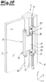
- the Fig. 3B shows the door leaf 2 in an opening position, whereby the Door hinge 5 is visible.
- the door hinge 5 comprises a frame body 11 and a leaf body 12, both of which - as explained further below - are designed in several parts.
- the leaf body 12 engages with a hinge portion 13 in a receiving space 14 of the frame body 11, wherein the leaf body 12 is pivotally connected to the frame body 11 at the end of the hinge portion 13 and wherein a corresponding pivot axis 5 is located within the recess A of the door frame 1.
- the recess A in the embodiment is located approximately halfway in the reveal surface 8 and in the boundary surface 9.
- the pivot axis S is then arranged as far as possible in the direction of the outside in the embodiment shown and thus in the area of the boundary surface 9 with respect to the second horizontal direction y (see also below Fig. 5 ).
- the Fig. 4 shows the section according to the Fig. 3A in a view of the inside of the door leaf 2 and door frame 1. It can be seen that in the closed position shown, the leaf body 12 is completely inserted into the recess A along the first horizontal direction x and is thus barely visible. In the closed position, the entire arrangement of the door hinges 5 is therefore exceptionally inconspicuous and restrained.
- the Fig. 5 shows a part of the building door in a cross-section.
- the fastening of the leaf body 12 can be seen particularly clearly only on the inside of the door leaf 2, with the leaf body 12 along the first horizontal direction x does not protrude from the recess A and is approximately flush with the adjacent reveal surface 8.
- the flush arrangement of the outside of the door leaf 2 with the adjacent mirror section 10 can also be seen.
- the pivot axis S is oriented as far as possible towards the outside with respect to the recess A, so that the door leaf 2 can be swung open without jamming even with a simple hinge construction with exactly one pivot axis S. It is also advantageous that the leaf body 12 is only attached to the inside of the door leaf 2 and thus does not lead to a widening along the first horizontal direction x, which could lead to jamming during an opening movement.
- FIG. 6 and Fig. 7 Further details of the building door and the two door hinges can be found in the Fig. 6 and Fig. 7 , whereby the components of the exemplary door hinge 5 are shown and arranged in a largely identical manner. For a better recognition of details, Fig. 7 However, in the exploded view the door frame 1 and the door leaf 2 are omitted.
- the frame body 11 comprises a base body 16 and an insert 17, wherein the insert 17 accommodates screw heads of adjusting screws 18, with which the insert 17 can be positioned along the first horizontal direction x relative to the base body 16.
- the base body 16 further comprises fastening holes 19, wherein the frame body 11 is fastened to the door frame 1 with fastening screws (not shown) which extend through the fastening holes 19.
- the cover plates 15 are then provided, which for the sake of simplicity are in the Fig. 6 and 7 omitted are.
- the leaf body 12 is also designed in several parts and comprises a fastening part 20 and a separately formed hinge part 21. As described further below, this has the advantage that the fastening part 20 and the hinge part 21 can only be connected to one another when the door leaf 2 is mounted on the door frame 1, whereby a height adjustment can also be realized with a screw.
- the hinge part 21 also comprises the hinge tab section 13, wherein the corresponding holes in the insert 17 and the hinge tab section 13 are shown for the articulated connection of the sash body 12 and the frame body 11, but not the associated pivot pin.
- the fastening part 20 has a contact surface 22 with which the fastening part 20 is glued to the inside of the door leaf 2. Such a bonding can also take place in particular before the fastening part 20 is connected to the hinge part 21.
- the fastening part 20 has two connection formations 23 opposite the contact surface 22, each in the form of a projection, wherein a vertical bore 24 is provided in each connection formation 23.
- the band part 21 has, adjacent to the band flap section 13, a connecting section 25 with openings 26 which are provided for receiving the connection formations 23.
- FIG. 6 and 7 It can be seen that the openings 26 extend over a greater height than the respective associated connection formations 23, so that even after the connection of the fastening part 20 to the band part 21 by a connecting pin 27, an adjustment along the vertical direction z is still possible.
- a connecting pin (not shown) is with regard to the Fig. 6 and 7 also provided on the underside of the wing body 12.
- An adjustment can be made at the upper connection formation 23 and/or the lower connection formation 23.
- a screwing means in the form of a threaded pin can be provided, which engages in a thread in the vertical bore 24 and/or in the connecting section 25, wherein the adjustment can then be made by adjusting the threaded pin.
- Suitable embodiments are known to the person skilled in the art.
- Fig. 8 shows a vertical section in the area of the connection formations 23 with the vertical holes 24. If, for example, before mounting the door hinge 5, the connection formations 23 of the fastening part 20 are inserted into associated openings 26 on the connecting section 25 of the hinge part 21, the door leaf 2 with the fastening part 20 attached to it will sag downwards until the connection formations 23 strike the lower edge of the associated opening 26. If, for example, the vertical hole 24 of the upper connection formation 23 is equipped with an internal thread and the connecting pin 27 in the form of a threaded pin is screwed in from above, the connection formation 23 and thus the entire door leaf 2 can be raised as desired with an appropriate screw-in depth.
Landscapes
- Engineering & Computer Science (AREA)
- Mechanical Engineering (AREA)
- Civil Engineering (AREA)
- Structural Engineering (AREA)
- Wing Frames And Configurations (AREA)
- Hinges (AREA)
Claims (8)
- Porte d'un bâtiment, pourvue d'un chambranle (1), d'un battant de porte (2) non feuillé et d'au moins une paumelle (5), à l'aide de laquelle le battant de porte (2) est assemblé de manière mobile en pivotement avec le chambranle (1), dans une position de fermeture, le battant de porte (2) s'étendant dans une direction (z) verticale et le long d'une largeur de panneau de porte dans une première direction (x) horizontale, le chambranle (1) comportant sur un côté de paumelle un intrados (4) pourvu d'une surface d'intrados (8), d'un niveau de feuillure (7) et d'une surface de délimitation (9) latéralement adjacente au battant de porte (2) dans la position de fermeture, sur le niveau de feuillure (7) une partie épaulée (3) tournée vers la face intérieure du battant de porte (2) assemblant l'une avec l'autre la surface d'intrados (8) et la surface de délimitation (9), un corps de chambranle (11) de la paumelle (5) étant inséré dans un évidement (A) de l'intrados (4) et dans la position de fermeture, une partie d'un corps de battant (12) de la paumelle (5) étant placée à l'intérieur de l'évidement (A), caractérisée en ce que le corps de battant (12) est placé et fixé exclusivement sur la face intérieure du battant de porte (2) et en ce que le corps de chambranle (11) et le corps de battant (12) sont assemblés par l'intermédiaire de précisément un axe de pivotement (S), lequel est placé à l'intérieur de l'évidement (A).
- Porte d'un bâtiment selon la revendication 1, caractérisée en ce que le corps de battant (12) est collé avec le battant de porte (2).
- Porte d'un bâtiment selon la revendication 1 ou 2, caractérisée en ce que dans la position de fermeture, le corps de battant (12) déborde le long de la première direction (x) horizontale de moins de 10 mm par rapport à la surface d'intrados (8) et est notamment à fleur de surface avec la surface d'intrados (8) ou est en retrait par rapport à la surface d'intrados (8).
- Porte d'un bâtiment selon l'une quelconque des revendications 1 à 3, caractérisée en ce que le battant de porte (2) est constitué en verre.
- Porte d'un bâtiment selon l'une quelconque des revendications 1 à 4, caractérisée en ce que le chambranle (1) comporte une partie miroir (10) se raccordant sur l'intrados (4), laquelle, dans la position de fermeture est à fleur de surface ou sensiblement à fleur de surface avec une face extérieure du battant de porte (2).
- Porte d'un bâtiment selon l'une quelconque des revendications 1 à 5, caractérisée en ce que le corps de chambranle (11) et / ou le corps de battant (12) est / sont conçu(s) en plusieurs parties.
- Porte d'un bâtiment selon la revendication 6, caractérisée en ce que le corps de battant (12) comporte une pièce de fixation (20) fixée sur le battant de porte (2) et une pièce de paumelle (21) séparée, pourvue d'une partie de patte (13) de paumelle, la pièce de fixation (20) et la pièce de paumelle (21) étant ajustables l'une contre l'autre.
- Porte d'un bâtiment selon la revendication 6 ou 7, caractérisée en ce que le corps de chambranle (11) en plusieurs parties comprend un corps de base (16) et un insert (17), lesquels sont ajustables l'un contre l'autre.
Applications Claiming Priority (1)
| Application Number | Priority Date | Filing Date | Title |
|---|---|---|---|
| DE102020122730.2A DE102020122730B3 (de) | 2020-08-31 | 2020-08-31 | Gebäudetür und Türband für eine Gebäudetür |
Publications (3)
| Publication Number | Publication Date |
|---|---|
| EP4001574A1 EP4001574A1 (fr) | 2022-05-25 |
| EP4001574C0 EP4001574C0 (fr) | 2024-10-09 |
| EP4001574B1 true EP4001574B1 (fr) | 2024-10-09 |
Family
ID=75584237
Family Applications (1)
| Application Number | Title | Priority Date | Filing Date |
|---|---|---|---|
| EP21187713.9A Active EP4001574B1 (fr) | 2020-08-31 | 2021-07-26 | Porte de bâtiment et charnière pour une porte de bâtiment |
Country Status (2)
| Country | Link |
|---|---|
| EP (1) | EP4001574B1 (fr) |
| DE (1) | DE102020122730B3 (fr) |
Family Cites Families (11)
| Publication number | Priority date | Publication date | Assignee | Title |
|---|---|---|---|---|
| FR2324839B1 (fr) * | 1975-07-02 | 1978-02-24 | Paumellerie Electrique | Paumelle pour le montage d'une porte en verre |
| DE29516023U1 (de) * | 1995-10-10 | 1997-02-06 | Pauli + Sohn GmbH, 51545 Waldbröl | Beschlag |
| DE19945184A1 (de) * | 1999-09-21 | 2001-04-12 | Fischbach Joachim | Befestigungsvorrichtung für plattenförmige Bauteile |
| DE19960724C2 (de) * | 1999-12-16 | 2003-02-06 | Dorma Gmbh & Co Kg | Justierbarer Beschlag |
| EP1308592B1 (fr) * | 2001-10-31 | 2009-12-09 | Simonswerk, Gesellschaft mit beschränkter Haftung | Charnière de porte pour arrangement caché entre battant et cadre de porte |
| DE102009052417A1 (de) * | 2008-12-02 | 2010-06-10 | Dorma Gmbh + Co. Kg | Beschlag für eine Glastür |
| DE102017100252B3 (de) * | 2017-01-09 | 2017-09-28 | Simonswerk Gmbh | Türanordnung |
| DE102017100270B3 (de) * | 2017-01-09 | 2018-01-11 | Simonswerk Gmbh | Türband sowie Zimmertür |
| DE102017100254B3 (de) * | 2017-01-09 | 2018-01-04 | Simonswerk Gmbh | Türanordnung |
| DE202017100143U1 (de) | 2017-01-12 | 2017-02-06 | Simonswerk Gmbh | Türanordnung |
| EP3683388A1 (fr) * | 2019-01-15 | 2020-07-22 | Robert Peer | Charnière |
-
2020
- 2020-08-31 DE DE102020122730.2A patent/DE102020122730B3/de active Active
-
2021
- 2021-07-26 EP EP21187713.9A patent/EP4001574B1/fr active Active
Also Published As
| Publication number | Publication date |
|---|---|
| EP4001574C0 (fr) | 2024-10-09 |
| DE102020122730B3 (de) | 2021-05-12 |
| EP4001574A1 (fr) | 2022-05-25 |
Similar Documents
| Publication | Publication Date | Title |
|---|---|---|
| DE10021330C2 (de) | Verstellbare Scharnier-Rahmen-Anordnung | |
| DE202017100143U1 (de) | Türanordnung | |
| DE10034071B4 (de) | Einrichtung zum Verschließen einer Öffnung | |
| DE202014102793U1 (de) | Türblattseitiges Bandteil eines Türbandes und Anordnung hiermit | |
| EP2369109B1 (fr) | Penture pour des portes de fermeture de bâtiments en bois feuillurées | |
| DE2748623A1 (de) | Beschlag fuer einen glasfluegel, insbesondere fuer eine ganzglastuer | |
| DE102005022042B3 (de) | Mehrdimensional verstellbares Türband an einem Türflügel | |
| DE29514335U1 (de) | Stahlzargen-Scharnierkonstruktion | |
| EP0600102B1 (fr) | Ferrure pour des battants pouvant être basculés et déplacés vers un plan parallèle et qui sont verrouillables en position formée, en position basculée ou en position parallèle | |
| EP4001574B1 (fr) | Porte de bâtiment et charnière pour une porte de bâtiment | |
| DE602004007009T2 (de) | Verbessertes kippfenster mit arretiermittel | |
| EP3768931A1 (fr) | Unité d'étanchéité | |
| EP0887501B1 (fr) | Ferrure arrangée en feuillure pour fenêtre, porte ou similaire | |
| DE102007025857A1 (de) | Gelenkband für Türen oder Fenster | |
| DE102019100388B3 (de) | Türvorrichtung mit flächenbündiger Abschlussebene sowie Wandsystem | |
| EP0674077B1 (fr) | Porte | |
| WO2004018815A1 (fr) | Partie de penture pour penture de porte, de fenetre ou similaire | |
| DE4403524A1 (de) | Anordnung eines Ecklagers an einem Fenster oder einer Tür sowie für diese Anordnung bestimmtes Ecklager | |
| EP3985219B1 (fr) | Agencement doté d'un joint d'étanchéité de plancher pour une porte, un espace intermédiaire se trouvant entre un battant de porte et un cadre, dans lequel passe le seul axe de rotation du battant | |
| EP1375802B1 (fr) | Porte coupe-feu vitrée avec couverture pour charnière de porte | |
| EP0787873B1 (fr) | Profil de verrouillage | |
| EP0616106B1 (fr) | Fenêtre ou porte avec ferrure de charnière | |
| DE19541042C2 (de) | Aluminium- oder Kunststoffenster, -tür oder dergleichen mit Gelenkverbindung | |
| DE20310889U1 (de) | Spaltlüftungsvorrichtung | |
| EP2090730B1 (fr) | Dispositif de verrouillage |
Legal Events
| Date | Code | Title | Description |
|---|---|---|---|
| PUAI | Public reference made under article 153(3) epc to a published international application that has entered the european phase |
Free format text: ORIGINAL CODE: 0009012 |
|
| STAA | Information on the status of an ep patent application or granted ep patent |
Free format text: STATUS: THE APPLICATION HAS BEEN PUBLISHED |
|
| AK | Designated contracting states |
Kind code of ref document: A1 Designated state(s): AL AT BE BG CH CY CZ DE DK EE ES FI FR GB GR HR HU IE IS IT LI LT LU LV MC MK MT NL NO PL PT RO RS SE SI SK SM TR |
|
| STAA | Information on the status of an ep patent application or granted ep patent |
Free format text: STATUS: REQUEST FOR EXAMINATION WAS MADE |
|
| 17P | Request for examination filed |
Effective date: 20220614 |
|
| RBV | Designated contracting states (corrected) |
Designated state(s): AL AT BE BG CH CY CZ DE DK EE ES FI FR GB GR HR HU IE IS IT LI LT LU LV MC MK MT NL NO PL PT RO RS SE SI SK SM TR |
|
| GRAP | Despatch of communication of intention to grant a patent |
Free format text: ORIGINAL CODE: EPIDOSNIGR1 |
|
| STAA | Information on the status of an ep patent application or granted ep patent |
Free format text: STATUS: GRANT OF PATENT IS INTENDED |
|
| INTG | Intention to grant announced |
Effective date: 20240523 |
|
| GRAS | Grant fee paid |
Free format text: ORIGINAL CODE: EPIDOSNIGR3 |
|
| GRAA | (expected) grant |
Free format text: ORIGINAL CODE: 0009210 |
|
| STAA | Information on the status of an ep patent application or granted ep patent |
Free format text: STATUS: THE PATENT HAS BEEN GRANTED |
|
| AK | Designated contracting states |
Kind code of ref document: B1 Designated state(s): AL AT BE BG CH CY CZ DE DK EE ES FI FR GB GR HR HU IE IS IT LI LT LU LV MC MK MT NL NO PL PT RO RS SE SI SK SM TR |
|
| REG | Reference to a national code |
Ref country code: CH Ref legal event code: EP |
|
| REG | Reference to a national code |
Ref country code: DE Ref legal event code: R096 Ref document number: 502021005402 Country of ref document: DE |
|
| REG | Reference to a national code |
Ref country code: IE Ref legal event code: FG4D Free format text: LANGUAGE OF EP DOCUMENT: GERMAN |
|
| U01 | Request for unitary effect filed |
Effective date: 20241023 |
|
| U07 | Unitary effect registered |
Designated state(s): AT BE BG DE DK EE FI FR IT LT LU LV MT NL PT RO SE SI Effective date: 20241107 |
|
| PG25 | Lapsed in a contracting state [announced via postgrant information from national office to epo] |
Ref country code: HR Free format text: LAPSE BECAUSE OF FAILURE TO SUBMIT A TRANSLATION OF THE DESCRIPTION OR TO PAY THE FEE WITHIN THE PRESCRIBED TIME-LIMIT Effective date: 20241009 Ref country code: IS Free format text: LAPSE BECAUSE OF FAILURE TO SUBMIT A TRANSLATION OF THE DESCRIPTION OR TO PAY THE FEE WITHIN THE PRESCRIBED TIME-LIMIT Effective date: 20250209 |
|
| PG25 | Lapsed in a contracting state [announced via postgrant information from national office to epo] |
Ref country code: ES Free format text: LAPSE BECAUSE OF FAILURE TO SUBMIT A TRANSLATION OF THE DESCRIPTION OR TO PAY THE FEE WITHIN THE PRESCRIBED TIME-LIMIT Effective date: 20241009 |
|
| PG25 | Lapsed in a contracting state [announced via postgrant information from national office to epo] |
Ref country code: NO Free format text: LAPSE BECAUSE OF FAILURE TO SUBMIT A TRANSLATION OF THE DESCRIPTION OR TO PAY THE FEE WITHIN THE PRESCRIBED TIME-LIMIT Effective date: 20250109 |
|
| PG25 | Lapsed in a contracting state [announced via postgrant information from national office to epo] |
Ref country code: GR Free format text: LAPSE BECAUSE OF FAILURE TO SUBMIT A TRANSLATION OF THE DESCRIPTION OR TO PAY THE FEE WITHIN THE PRESCRIBED TIME-LIMIT Effective date: 20250110 |
|
| PG25 | Lapsed in a contracting state [announced via postgrant information from national office to epo] |
Ref country code: PL Free format text: LAPSE BECAUSE OF FAILURE TO SUBMIT A TRANSLATION OF THE DESCRIPTION OR TO PAY THE FEE WITHIN THE PRESCRIBED TIME-LIMIT Effective date: 20241009 |
|
| PG25 | Lapsed in a contracting state [announced via postgrant information from national office to epo] |
Ref country code: RS Free format text: LAPSE BECAUSE OF FAILURE TO SUBMIT A TRANSLATION OF THE DESCRIPTION OR TO PAY THE FEE WITHIN THE PRESCRIBED TIME-LIMIT Effective date: 20250109 |
|
| PG25 | Lapsed in a contracting state [announced via postgrant information from national office to epo] |
Ref country code: SM Free format text: LAPSE BECAUSE OF FAILURE TO SUBMIT A TRANSLATION OF THE DESCRIPTION OR TO PAY THE FEE WITHIN THE PRESCRIBED TIME-LIMIT Effective date: 20241009 |
|
| PG25 | Lapsed in a contracting state [announced via postgrant information from national office to epo] |
Ref country code: SK Free format text: LAPSE BECAUSE OF FAILURE TO SUBMIT A TRANSLATION OF THE DESCRIPTION OR TO PAY THE FEE WITHIN THE PRESCRIBED TIME-LIMIT Effective date: 20241009 |
|
| PG25 | Lapsed in a contracting state [announced via postgrant information from national office to epo] |
Ref country code: CZ Free format text: LAPSE BECAUSE OF FAILURE TO SUBMIT A TRANSLATION OF THE DESCRIPTION OR TO PAY THE FEE WITHIN THE PRESCRIBED TIME-LIMIT Effective date: 20241009 |
|
| PLBE | No opposition filed within time limit |
Free format text: ORIGINAL CODE: 0009261 |
|
| STAA | Information on the status of an ep patent application or granted ep patent |
Free format text: STATUS: NO OPPOSITION FILED WITHIN TIME LIMIT |
|
| U20 | Renewal fee for the european patent with unitary effect paid |
Year of fee payment: 5 Effective date: 20250727 |
|
| 26N | No opposition filed |
Effective date: 20250710 |
|
| REG | Reference to a national code |
Ref country code: CH Ref legal event code: H13 Free format text: ST27 STATUS EVENT CODE: U-0-0-H10-H13 (AS PROVIDED BY THE NATIONAL OFFICE) Effective date: 20260224 |
|
| GBPC | Gb: european patent ceased through non-payment of renewal fee |
Effective date: 20250726 |
|
| PG25 | Lapsed in a contracting state [announced via postgrant information from national office to epo] |
Ref country code: GB Free format text: LAPSE BECAUSE OF NON-PAYMENT OF DUE FEES Effective date: 20250726 |
|
| PG25 | Lapsed in a contracting state [announced via postgrant information from national office to epo] |
Ref country code: CH Free format text: LAPSE BECAUSE OF NON-PAYMENT OF DUE FEES Effective date: 20250731 |