EP4001602A1 - Agencement de chauffage par gaz d'échappement - Google Patents
Agencement de chauffage par gaz d'échappement Download PDFInfo
- Publication number
- EP4001602A1 EP4001602A1 EP21202549.8A EP21202549A EP4001602A1 EP 4001602 A1 EP4001602 A1 EP 4001602A1 EP 21202549 A EP21202549 A EP 21202549A EP 4001602 A1 EP4001602 A1 EP 4001602A1
- Authority
- EP
- European Patent Office
- Prior art keywords
- heating unit
- heating
- exhaust gas
- longitudinal end
- carrier element
- Prior art date
- Legal status (The legal status is an assumption and is not a legal conclusion. Google has not performed a legal analysis and makes no representation as to the accuracy of the status listed.)
- Granted
Links
Images



Classifications
-
- F—MECHANICAL ENGINEERING; LIGHTING; HEATING; WEAPONS; BLASTING
- F01—MACHINES OR ENGINES IN GENERAL; ENGINE PLANTS IN GENERAL; STEAM ENGINES
- F01N—GAS-FLOW SILENCERS OR EXHAUST APPARATUS FOR MACHINES OR ENGINES IN GENERAL; GAS-FLOW SILENCERS OR EXHAUST APPARATUS FOR INTERNAL-COMBUSTION ENGINES
- F01N3/00—Exhaust or silencing apparatus having means for purifying, rendering innocuous, or otherwise treating exhaust
- F01N3/02—Exhaust or silencing apparatus having means for purifying, rendering innocuous, or otherwise treating exhaust for cooling, or for removing solid constituents of, exhaust
- F01N3/021—Exhaust or silencing apparatus having means for purifying, rendering innocuous, or otherwise treating exhaust for cooling, or for removing solid constituents of, exhaust by means of filters
- F01N3/023—Exhaust or silencing apparatus having means for purifying, rendering innocuous, or otherwise treating exhaust for cooling, or for removing solid constituents of, exhaust by means of filters using means for regenerating the filters, e.g. by burning trapped particles
- F01N3/027—Exhaust or silencing apparatus having means for purifying, rendering innocuous, or otherwise treating exhaust for cooling, or for removing solid constituents of, exhaust by means of filters using means for regenerating the filters, e.g. by burning trapped particles using electric or magnetic heating means
- F01N3/0275—Exhaust or silencing apparatus having means for purifying, rendering innocuous, or otherwise treating exhaust for cooling, or for removing solid constituents of, exhaust by means of filters using means for regenerating the filters, e.g. by burning trapped particles using electric or magnetic heating means using electric discharge means
-
- F—MECHANICAL ENGINEERING; LIGHTING; HEATING; WEAPONS; BLASTING
- F01—MACHINES OR ENGINES IN GENERAL; ENGINE PLANTS IN GENERAL; STEAM ENGINES
- F01N—GAS-FLOW SILENCERS OR EXHAUST APPARATUS FOR MACHINES OR ENGINES IN GENERAL; GAS-FLOW SILENCERS OR EXHAUST APPARATUS FOR INTERNAL-COMBUSTION ENGINES
- F01N3/00—Exhaust or silencing apparatus having means for purifying, rendering innocuous, or otherwise treating exhaust
- F01N3/02—Exhaust or silencing apparatus having means for purifying, rendering innocuous, or otherwise treating exhaust for cooling, or for removing solid constituents of, exhaust
- F01N3/021—Exhaust or silencing apparatus having means for purifying, rendering innocuous, or otherwise treating exhaust for cooling, or for removing solid constituents of, exhaust by means of filters
- F01N3/023—Exhaust or silencing apparatus having means for purifying, rendering innocuous, or otherwise treating exhaust for cooling, or for removing solid constituents of, exhaust by means of filters using means for regenerating the filters, e.g. by burning trapped particles
- F01N3/027—Exhaust or silencing apparatus having means for purifying, rendering innocuous, or otherwise treating exhaust for cooling, or for removing solid constituents of, exhaust by means of filters using means for regenerating the filters, e.g. by burning trapped particles using electric or magnetic heating means
-
- F—MECHANICAL ENGINEERING; LIGHTING; HEATING; WEAPONS; BLASTING
- F01—MACHINES OR ENGINES IN GENERAL; ENGINE PLANTS IN GENERAL; STEAM ENGINES
- F01N—GAS-FLOW SILENCERS OR EXHAUST APPARATUS FOR MACHINES OR ENGINES IN GENERAL; GAS-FLOW SILENCERS OR EXHAUST APPARATUS FOR INTERNAL-COMBUSTION ENGINES
- F01N3/00—Exhaust or silencing apparatus having means for purifying, rendering innocuous, or otherwise treating exhaust
- F01N3/08—Exhaust or silencing apparatus having means for purifying, rendering innocuous, or otherwise treating exhaust for rendering innocuous
- F01N3/10—Exhaust or silencing apparatus having means for purifying, rendering innocuous, or otherwise treating exhaust for rendering innocuous by thermal or catalytic conversion of noxious components of exhaust
- F01N3/18—Exhaust or silencing apparatus having means for purifying, rendering innocuous, or otherwise treating exhaust for rendering innocuous by thermal or catalytic conversion of noxious components of exhaust characterised by methods of operation; Control
- F01N3/20—Exhaust or silencing apparatus having means for purifying, rendering innocuous, or otherwise treating exhaust for rendering innocuous by thermal or catalytic conversion of noxious components of exhaust characterised by methods of operation; Control specially adapted for catalytic conversion
- F01N3/2006—Periodically heating or cooling catalytic reactors, e.g. at cold starting or overheating
- F01N3/2013—Periodically heating or cooling catalytic reactors, e.g. at cold starting or overheating using electric or magnetic heating means
-
- H—ELECTRICITY
- H05—ELECTRIC TECHNIQUES NOT OTHERWISE PROVIDED FOR
- H05B—ELECTRIC HEATING; ELECTRIC LIGHT SOURCES NOT OTHERWISE PROVIDED FOR; CIRCUIT ARRANGEMENTS FOR ELECTRIC LIGHT SOURCES, IN GENERAL
- H05B3/00—Ohmic-resistance heating
- H05B3/02—Details
- H05B3/06—Heater elements structurally combined with coupling elements or holders
-
- F—MECHANICAL ENGINEERING; LIGHTING; HEATING; WEAPONS; BLASTING
- F01—MACHINES OR ENGINES IN GENERAL; ENGINE PLANTS IN GENERAL; STEAM ENGINES
- F01N—GAS-FLOW SILENCERS OR EXHAUST APPARATUS FOR MACHINES OR ENGINES IN GENERAL; GAS-FLOW SILENCERS OR EXHAUST APPARATUS FOR INTERNAL-COMBUSTION ENGINES
- F01N2240/00—Combination or association of two or more different exhaust treating devices, or of at least one such device with an auxiliary device, not covered by indexing codes F01N2230/00 or F01N2250/00, one of the devices being
- F01N2240/16—Combination or association of two or more different exhaust treating devices, or of at least one such device with an auxiliary device, not covered by indexing codes F01N2230/00 or F01N2250/00, one of the devices being an electric heater, i.e. a resistance heater
-
- F—MECHANICAL ENGINEERING; LIGHTING; HEATING; WEAPONS; BLASTING
- F01—MACHINES OR ENGINES IN GENERAL; ENGINE PLANTS IN GENERAL; STEAM ENGINES
- F01N—GAS-FLOW SILENCERS OR EXHAUST APPARATUS FOR MACHINES OR ENGINES IN GENERAL; GAS-FLOW SILENCERS OR EXHAUST APPARATUS FOR INTERNAL-COMBUSTION ENGINES
- F01N2260/00—Exhaust treating devices having provisions not otherwise provided for
- F01N2260/10—Exhaust treating devices having provisions not otherwise provided for for avoiding stress caused by expansions or contractions due to temperature variations
-
- Y—GENERAL TAGGING OF NEW TECHNOLOGICAL DEVELOPMENTS; GENERAL TAGGING OF CROSS-SECTIONAL TECHNOLOGIES SPANNING OVER SEVERAL SECTIONS OF THE IPC; TECHNICAL SUBJECTS COVERED BY FORMER USPC CROSS-REFERENCE ART COLLECTIONS [XRACs] AND DIGESTS
- Y02—TECHNOLOGIES OR APPLICATIONS FOR MITIGATION OR ADAPTATION AGAINST CLIMATE CHANGE
- Y02T—CLIMATE CHANGE MITIGATION TECHNOLOGIES RELATED TO TRANSPORTATION
- Y02T10/00—Road transport of goods or passengers
- Y02T10/10—Internal combustion engine [ICE] based vehicles
- Y02T10/12—Improving ICE efficiencies
Definitions
- the present invention relates to an exhaust gas heating arrangement for an exhaust system of an internal combustion engine with a heating unit housing through which exhaust gas can flow.
- An exhaust gas heating arrangement for an exhaust system of an internal combustion engine in a vehicle in which a spirally wound heating unit is arranged in a tubular heating unit housing with a substantially circular peripheral contour.
- the heating unit comprises a sheathed heating conductor with a sheath and a heating conductor element running in the sheath. By applying an electrical voltage to the heating element, this is traversed by an electric current.
- the heat that is generated because of the electrical resistance is transferred via the jacket to a heat transfer formation surrounding the jacket on its outside.
- the heat transfer formation has a meandering structure with heat transfer sections which are arranged essentially parallel to one another, are connected to one another in connection sections and have the jacket passing through them in a respective central area. Exhaust gas flowing through the heating unit housing in an exhaust gas main flow direction essentially corresponding to the direction of a housing longitudinal axis flows along the surfaces of the heat transfer sections or connection sections and absorbs heat in the process.
- an exhaust gas heating arrangement in particular in a starting phase of the operation of an internal combustion engine, in which the exhaust gas emitted by the internal combustion engine has a comparatively low temperature and also the exhaust gas treatment arrangements provided in the exhaust system, in particular one or more catalytic converters, can still have a comparatively low temperature and thus an efficient reduction in the proportion of pollutants contained in the exhaust gas cannot be achieved, the exhaust gas flow is heated and heat is thus placed in system areas downstream of the exhaust gas heating arrangement, in particular Exhaust gas treatment arrangements, enter. As a result, the period of time during which efficient exhaust gas purification cannot take place at the start of operation of the internal combustion engine can be significantly reduced.
- an exhaust gas heating arrangement for an exhaust system of an internal combustion engine comprising a heating unit housing through which exhaust gas can flow and a plurality of heating units which are arranged in the heating unit housing and are elongated in the direction of a heating unit longitudinal axis, each with a first heating unit longitudinal end area and a second heating unit longitudinal end area , wherein the heating units are supported in their first heating unit longitudinal end areas and their second heating unit longitudinal end areas by means of a support structure with respect to the heating unit housing, wherein at least one, preferably each heating unit with its first heating unit longitudinal end area and/or its second heating unit longitudinal end area on the support structure in movably supported in the heating unit longitudinal direction.
- the heating units are movably supported in at least one of their end regions with respect to the heating unit housing, so that overloading of those regions in which the heating units are supported with respect to the heating unit housing, which occurs during heating operation due to thermally induced expansion of the heating units, is avoided. Due to the relative movement between the heating units in at least one of their longitudinal end regions and the housing made possible by the structure according to the invention, the change in length that occurs when the heating units are heated and also cooled can be compensated for or absorbed.
- the support structure in association with the first longitudinal end areas of the heating unit, have a bearing on the heating unit housing, supported by the heating units in the area first carrier element through which carrier element through-openings pass, or/and that the carrier structure comprises, in association with the second longitudinal end areas of the heating unit, a second carrier element carried on the heating unit housing and penetrated by the heating units in the area of carrier element through-openers.
- At least one, preferably each heating unit can pass through a carrier element passage opening in its first longitudinal end area of the heating unit in such a way that the first longitudinal end area of the heating unit can be moved in the direction of the longitudinal axis of the heating unit with respect to the first carrier element, and/or at least one, preferably each heating unit pass through a carrier element passage opening in its second longitudinal end area of the heating unit in such a way that the second longitudinal end area of the heating unit can be moved in the direction of the longitudinal axis of the heating unit with respect to the second carrier element.
- the heating units can be held in the respective carrier element passage openings, generating a friction fit in such a way that on the one hand a relative movement with respect to a respective carrier element in the area of the carrier element passage openings is possible, and on the other hand energy can also be dissipated by this relative movement and thus the occurrence of vibrations is prevented can be.
- the first carrier element is flexible in the direction of the longitudinal axis of the heating unit, and that at least one, preferably every heating unit is fixed to the first carrier element in its first longitudinal end region of the heating unit, and/or that the second support element is flexible in the direction of the longitudinal axis of the heating unit, and that at least one, preferably each heating unit is fixed in its second longitudinal end region of the heating unit to the second support element.
- the flexibility i.e.
- essentially elastic deformability, of the support elements thus enables movement of the heating units, which are firmly connected to them, for example by soldering, with respect to the heating unit housing, so that the thermally induced change in length of the heating units can be compensated for by deformation of the support elements firmly connected to them, which in particular an excessive load on the areas generated, for example, by material connection or also a firm frictional connection, in which the heating units are firmly connected to a respective carrier element, is also avoided.
- the first carrier element is essentially U-shaped with two U-legs and a connecting web connecting the two U-legs
- first U-leg of the first support element is fixed to the heating unit housing and the support element passage openings of the first support element are provided in a second U-leg of the first support element and/or the connecting web of the first support element is arranged in the direction of an inflow side of the heating unit housing and/or that the second support element is essentially U-shaped with two U-legs and a connecting web connecting the two U-legs, with a first U-leg of the second support element being fixed to the heating unit housing and in a second U-leg of the second support element the carrier element ment through-openings of the second support element are provided and/or wherein the connecting web of the second support element is arranged in the direction of an inflow side of the heating unit housing.
- At least one heating unit in its first longitudinal end area of the heating unit is electrically conductively connected to at least one further heating unit in its first longitudinal end area and/or in its second The longitudinal end area of the heating unit is electrically conductively connected to at least one further heating unit in the second longitudinal end area of the heating unit.
- At least one heating unit can be electrically conductively connected to at least one further heating unit in its first longitudinal end region of the heating unit and electrically conductively connected to at least one other further heating unit in its second longitudinal end region.
- At least two, preferably all, heating units can be electrically connected in parallel with one another and/or at least two, preferably all, heating units can be electrically connected in series with one another.
- At least two, preferably all, heating units can be electrically conductively connected in their first heating unit longitudinal end regions to at least one further heating unit in a carrier element interior space bounded by the two U-legs of the first carrier element, and/or at least two preferably all heating units are electrically conductively connected in their second longitudinal end regions of the heating unit to at least one further heating unit in a support element interior space delimited by the two U-legs of the second support element.
- heating units pass through a housing passage opening of the heating unit housing in their first heating unit longitudinal end areas and be connected to one another or/ and are electrically conductively connected to at least one additional heating unit on the outside of the heating unit housing, and/or that at least two, preferably all, heating units pass through a housing passage opening of the heating unit housing in their second longitudinal end areas of the heating unit and connect to one another and/or to at least one additional heating unit are electrically conductively connected to the outside of the heating unit housing.
- a first heating unit connection space, sealed essentially gas-tight by at least one cover element can be provided on the outside of the heating unit housing in association with the first longitudinal heating unit end areas for the electrical connection of at least two heating units in their first longitudinal heating unit end areas outside of the heating unit housing, and/or a second heating unit connection space, sealed essentially gas-tight by at least one cover element, for the electrical connection of at least two heating units in their second heating unit longitudinal end areas outside of the be provided heating unit housing.
- At least two, preferably all, heating units are arranged with the longitudinal axes of the heating unit essentially parallel to one another, or/and that at least two, preferably all of the heating units are arranged with the heating unit longitudinal axes lying in a plane that is essentially orthogonal to a longitudinal axis of the housing of the heating unit housing.
- at least one, preferably each, heating unit is elongated in a straight line along the longitudinal axis of the heating unit.
- Efficient flow of exhaust gas around the heating units can also be supported by the fact that the heating unit housing has a heating unit receiving area with a substantially rectangular inner peripheral contour, the heating units being arranged in the heating unit receiving area, and that the heating unit housing has a substantially round inner peripheral contour in an upstream connection area and/or has a substantially round inner peripheral contour in a downstream connection area.
- this creates the possibility of connecting the exhaust gas heating arrangement according to the invention to other system areas of an exhaust system, which generally have a round, for example circular, cross-sectional geometry, while in the area in which the heating units are arranged, almost the entire flow cross section is efficiently occupied by the heating units and thus the exhaust gas flowing through the heating unit housing is forced into thermal interaction with the heating units.
- the heating units can be designed, for example, as so-called sheathed heating conductors.
- at least one, preferably each, heating unit can comprise a jacket that is elongated in the direction of the longitudinal axis of the heating unit and a heating conductor element in the jacket and/or a heat transfer formation on an outside of the jacket.
- the heat transfer formation comprises a plurality of heat transfer sections that follow one another in the direction of the longitudinal axis of the heating unit and/or that in at least one, preferably each heating unit, the heat transfer formation is designed in a meandering manner with a plurality of heat transfer sections which are essentially parallel to one another and are connected to one another by connecting sections.
- at least one heat transfer formation can be provided on the outside of the jackets of at least two heating units.
- the heat transfer sections in a meandering structure By connecting individual heat transfer sections in a meandering structure, for example, an additional stiffening and thus a further increase in the natural frequency of the heat transfer formation is achieved.
- the provision of the heat transfer sections in a meandering structure also has the advantage that the heat transfer sections coupled to one another or adjoining one another in their lateral end regions have less of a tendency to fluttering movements in the exhaust gas flow.
- the or some of the successive heat transfer sections can also be provided separately and connected to one another, for example by soldering. This also leads to an increased rigidity of a respective heat transfer formation.
- the invention also relates to an exhaust system for an internal combustion engine, comprising at least one exhaust gas treatment arrangement, preferably a catalytic converter and/or particle filter, and an exhaust gas heating arrangement constructed according to the invention upstream of the at least one exhaust gas treatment arrangement.
- at least one exhaust gas treatment arrangement preferably a catalytic converter and/or particle filter
- an exhaust gas heating arrangement constructed according to the invention upstream of the at least one exhaust gas treatment arrangement.
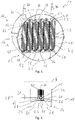
- FIGS. 1 and 2 show a first exemplary embodiment of an exhaust gas heating arrangement, generally designated 10, for an exhaust system of an internal combustion engine, for example in a vehicle.
- the exhaust gas heating arrangement 10 comprises a heating unit housing 16 constructed with two half-shells 12, 14.
- An inflow side 18 of the exhaust gas heating arrangement 10 or of the heating unit housing 16 can be seen at the rear, while an outflow side 20 of the exhaust gas heating arrangement 10 or of the heating unit housing 16 is located at the front.
- the heating unit housing 16 is constructed with three areas that follow one another in the direction of a longitudinal axis G of the housing.
- a heating unit receiving area 22 is provided centrally, in which the heating unit housing 16 is formed with a substantially rectangular, for example square, inner peripheral contour.
- the heating unit housing 16 is formed with an upstream connection area 24 with a substantially round, for example circular, inner peripheral contour.
- the heating unit housing 16 is formed with a substantially round, for example circular, inner peripheral contour and provides a downstream connection area 26 .
- the heating unit housing 16 can be connected to other system areas of an exhaust system.
- Each heating unit 32 comprises a sheathed heating conductor which is elongated in the direction of a longitudinal axis H of the heating unit and has a tubular, essentially rigid sheathing 34 constructed, for example, from metal material, and a heating conductor element 36 which runs inside the sheathing 34 and is kept electrically insulated from it by insulating material.
- a heat transfer formation 38 is provided for each heating unit 32, which in the exemplary embodiment shown comprises a meandering structure with a plurality of plate-like heat transfer sections 40 which follow one another in the direction of the longitudinal axes H of the heating unit and are penetrated, for example, in a central area by the respective jacket 34.
- the heat transfer sections 40 that follow one another in the direction of the longitudinal axes H of the heating unit are connected to one another in connection regions 42 that are similar to curvatures.
- the heat transfer formations 38 can be connected to the jacket 34 passing through them, for example by press fitting or shrinking, and/or can be connected to them in a material-locking manner, for example by soldering or the like.
- Each of the heating units 32 has a 1 overhead first heating unit longitudinal end region 44 and an in 1 second longitudinal end region 46 of the heating unit shown below.
- the heating units 32 are connected to the Heater unit housing 16 attached.
- the heating units 32 are connected to the heating unit housing 16 in the heating unit receiving region 22 via a U-shaped second support element 50 which is also bent from sheet metal, for example.
- the two carrier elements 48, 50 together form a carrier structure 52, by means of which the heating units 32 are carried on the heating unit housing 16.
- the heating units 32 are arranged in such a way that their longitudinal axes H of the heating unit are parallel to one another and lie in a plane that is essentially orthogonal to the longitudinal axis G of the housing.
- the total of six heating units 32 thus occupy essentially the entire cross section of the heating unit housing 16 through which exhaust gas can flow in the heating unit receiving area 22, so that an efficient thermal interaction between the exhaust gas and the heating units 32 is achieved.
- Each of the two U-shaped support elements 48, 50 of the support structure 52 has a material bonded to the inner surface of the heating unit housing 16, for example by a material connection such as, for. B. soldering or welding, fixed first U-legs 54, 56, as well as a second U-leg 62, 64 connected to the first U-leg 54, 56 by a respective connecting web 58, 60.
- the carrier elements 48, 50 are formed, for example, through openings 66, 68 provided by passages through which the heating elements 32 extend with their respective casing 34, so that in the area of their first heating unit longitudinal end areas 44 and their second heating unit longitudinal end areas 46 the heating units 32 are supported on the support elements 48, 50 and by means of these on the heating unit housing 16.
- the heating units 32 are connected to one another in an electrically conductive manner in the carrier element interior spaces delimited by the U-legs 54, 62 or 56, 64 and the connecting webs 58, 60.
- plate-like connecting elements 70 can be used, for example made of sheet metal material, which are connected to the heating conductor elements 36 of the heating elements 32 to be electrically conductively connected to one another, for example by material connection, such as, for example, B. soldering, are connected.
- the six adjacent heating units 32 are connected to each other in series.
- the two outermost heating units 32 are connected via respective bushings 72, 74 to a voltage source located outside of the heating unit housing 16, and the heating units 32 located between the two outermost heating units 32 are alternately in their first heating unit longitudinal end area 44 and their second heating unit longitudinal end area 46 with an immediately adjacent heating unit 32 is connected in an electrically conductive manner by one of the connecting elements 70, so that the heating units 32 are connected in series.
- the carrier elements 48, 50 are arranged in the heating unit housing 16 in such a way that their connecting webs 58, 60 are each oriented in the upstream direction, ie towards the inflow side 18.
- the areas in which the heating units 32 are connected to one another in an electrically conductive manner by the connecting elements 70 are thus shielded from the direct flow of exhaust gas and are thus protected from excessive heating.
- the support elements 48, 50 block the flow path in the first and second longitudinal heating unit end regions 44, 46, so that the exhaust gas flowing towards the heating units 32 in a main exhaust gas flow direction A is forced to flow around them in the region of the heat transfer formation 38.
- the heating units 32 can with their respective jacket 34 on the second U-leg 62 by material connection, for example by soldering, be fixed.
- the heating units 32 can be fixed in their second longitudinal end regions 46 of the heating unit on the second U-leg 64 of the second carrier element 50 by material connection, for example by soldering.
- the two carrier elements 48, 50 themselves are flexible, i.e. deformable, in the direction of the longitudinal axes H of the heating unit of the heating units 32, so that a change in length D of the heating units 32 that occurs during heating or cooling due to the flexibility, i.e.
- the elastic deformation of the carrier elements 48, 50 be included since the heating units 32 are movably supported in their first and second longitudinal end regions 44, 56 of the heating unit on the support structure 52 in the longitudinal direction H of the heating unit, in particular together with the respective second U-leg 62 or 64 in the direction of the longitudinal axes of the heating unit H are movably carried. Excessive loading of the connection areas of the heating units 32 with the carrier elements 48, 50 during the repeatedly occurring expansion or contraction of the heating units 32 in the direction of their longitudinal axes H of the heating unit is thus avoided.
- the carrier elements 48, 50 By selecting the material and also the shape of the carrier elements 48, 50, these can also be matched to the mass of the heating units 32 in such a way that vibration excitation can be avoided during operation. Furthermore, the elastic deformability of the carrier elements 48, 50 in the direction of the longitudinal axes H of the heating unit can be selected such that, particularly when heating units 32 heat up during heating operation and thus expand in the direction of the longitudinal axes H of the heating unit, a lateral evasive movement of the basically in In the direction of the longitudinal axes H of the heating unit, heating units 32 that extend essentially in a straight line is avoided, and thus mutual contact between heating units 32 that are directly adjacent to one another is also avoided.
- the heating units 32 can be held with their respective casing 34 in the carrier element through-openings 66, 68 or in the passages formed in the area of these carrier element through-openings 66, 68 by means of a press fit.
- This press fit can be so tight that it creates a firm connection with the support elements 48, 50 and thus the heating units 32 in their first and second longitudinal end regions 44, 46 of the heating unit together with the respective second U-legs 62, 64 of the support elements 48 , 50 can move in the direction of the longitudinal axes H of the heating unit.
- the heating units 32 in their first and second longitudinal heating unit ends 44, 46 in the carrier element passage openings 66, 68 can be carried in the direction of the longitudinal axes H of the heating unit.
- the carrier elements 48, 50 can be of essentially rigid design, so that the mobility of the heating units 32 in their respective longitudinal heating unit end regions 44, 46 is ensured in that the heating unit longitudinal end regions 44, 46 are in the respective second U Legs 62, 64 or the carrier element through-openings 66, 68 formed therein can move in the direction of the longitudinal axes H of the heating unit.
- the jackets 34 of the heating units 32 can be held in the respective carrier element through-openings 66, 68, with the generation of a frictional connection, this frictional connection being fundamentally designed in such a way that a relative movement between the longitudinal end regions of the heating unit 44, 46 and the second U-legs 62, 64 can occur during thermal expansion or contraction of the heating units 32.
- This relative mobility of the heating units 32 with respect to the carrier elements 48, 50 basically also achieves such a movement decoupling of the heating units 32 from the carrier elements 48, 50 that, when vibrations occur in an exhaust system, the heating units 32 cannot be excited to vibrate at their natural frequency.
- connection of the heating units 32 to the carrier elements 48, 50 described above can in principle be combined with one another.
- the heating units 32 can each be connected in the same way to the carrier elements 48, 50 or their second U-legs 62, 64 in their first heating-unit longitudinal end regions 44 and their second longitudinal end regions 46.
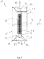
- An alternative embodiment of an exhaust gas heater assembly 10 is in the 3 and 4 shown.
- a plurality of heating units 32 are arranged next to one another transversely to the longitudinal axis G of the housing in the heating unit receiving area 22 of the heating unit housing 16, so that their longitudinal axes H of the heating unit are in turn essentially parallel to one another and in a plane which is essentially orthogonal to the longitudinal axis G of the housing, which the drawing level of 3 can match.
- the heating units 32 are carried with their first and second heating unit longitudinal end areas 44, 46 in the manner described above on the support elements 48, 50 or their second U-legs 62, 64 such that the heating unit longitudinal end areas 44, 46 thermally induced change in length can move in the direction of the longitudinal axes H of the heating unit.
- the heating units 32 with their first and second longitudinal heating unit end regions 44, 46, also pass through housing passage openings 76, 78 provided in the heating unit housing 16 in the heating unit receiving region 22. In the event of a thermally induced change in length, the heating units 32 can thus move in the region of the housing passage openings 76, 78 move.
- a first heating unit connection space 80 formed on the outside of the heating unit housing 16, in which the heating units 32 are conductively connected to one another in their first longitudinal heating unit end regions 44, and a second heating unit connecting space 82, in which the heating units 32 are connected to one another in an electrically conductive manner in their second heating unit longitudinal end regions 46, are sealed gas-tight by a respective substantially curved, cover-like cover element 84, 86.
- the cover elements 84, 86 can be connected to the heating unit housing 16 by material connection, for example soldering or welding.
- a total of six heating units 32 are connected in series with one another, with the connecting elements 70 now being positioned outside of the heating unit housing 16, so that the areas in which the connecting elements 70 are connected to the heating conductor elements 36 of the various heating units 32 are shielded from the oncoming flow of exhaust gas and are therefore protected from thermal overload.
- the design of the 3 and 4 could also with the embodiment of Figures 1 and 2 be combined.
- the heating units and 32 with their first heating unit longitudinal end areas 44 in the Figures 1 and 2 manner shown be integrated into the exhaust gas heating arrangement 10, while in their second heating unit longitudinal end areas 46, the heating units 32 in the 3 and 4 illustrated manner can be integrated into the exhaust gas heating assembly 10.
- the reverse arrangement is also possible.
- FIG. 10 A further alternative embodiment of an exhaust gas heating arrangement 10 is figure 5 shown.
- This basically corresponds to that in 3 and 4 illustrated design principle and differs from it insofar as the jackets 34 of several, in the illustrated embodiment example of all heating units 32 cooperate with the same heat transfer formation 38.
- This extends transversely to the longitudinal axis G of the housing and the exhaust gas main flow direction A, which is essentially oriented in the direction of the longitudinal axis G of the housing, across all heating units 32 and is therefore in contact with the casings 34 of all heating units 32.
- This heat transfer formation 38 also basically has the previously described formation meandering structure with the mutually essentially parallel, plate-like heat transfer sections 40 and the connecting sections 42 connecting them.
- each heating unit 32 has a heat transfer formation 38 exclusively assigned to it
- a respective heat transfer formation 38 can also be structured in a different way.
- a plurality of plate-like heat transfer sections constructed separately from one another can be provided on the respective jacket 34 .
- such a heat transfer formation 38 could also have a structure surrounding a respective jacket 34 wound in a helical manner.
- the Figures 6 to 9 represent various circuit examples for the electrical circuit of the heating units 32 provided in the heating unit housing 16.
- all heating units 32 are connected in parallel to one another.
- All heating units 32 are conductively connected to one another in their first longitudinal end regions 44 of the heating unit and in their second longitudinal end regions 46 of the heating unit by a respective connecting element 70 .
- the two bushings 72, 74 with which the heating units 32 can be connected to a voltage source, can be arranged in opposite areas of the heating unit housing and extend away from one another.
- the configuration shown leads to a voltage drop in the range of 12 V being able to occur in each of the heating units 32, which are constructed essentially identically to one another.
- FIG. 12 shows an exemplary embodiment in which three adjacent heating units 32 are connected in parallel with one another and the two packages of three heating units 32 connected in parallel with one another are connected in series with one another.
- Such a structure can be used, for example, when an on-board voltage system supplies a voltage of 24 V, in which case a voltage drop of approximately 12 V will occur in each of the heating units 32, which are essentially identical to one another.
- FIG. 12 shows an example embodiment in which three packages of two heating units 32 that are directly adjacent to one another and are connected in parallel are connected in series with one another.
- an on-board voltage system that can supply an on-board voltage of 36 V
- a voltage drop of approximately 12 V will also occur in this circuit in each of the heating units 32, which are constructed essentially identically to one another.
- the 9 shows the above with reference to in Figures 1 to 5 described serial circuit of all heating units 32.
- a voltage of about 12 V also drops in this circuit in each of the heating units 32, which are essentially identical to one another.
- the exhaust gas heating unit enables the exhaust gas flowing around the heating units to be heated efficiently, so that the exhaust gas can transfer the heat it absorbs to an exhaust gas treatment arrangement positioned downstream, for example a catalytic converter or particle filter, in particular in a starting phase of combustion operation, in order to heat it up and thus heat it up as quickly as possible to bring a state in which an efficient treatment of the exhaust gas and thus an efficient reduction of the pollutant content in the exhaust gas can be achieved.
- the design of the heating unit housing with the downstream connection area that widens like a funnel at the heating unit receiving area, in which a transition to a round, for example circular or elliptical, cross-sectional contour is achieved, allows the heating unit housing to be integrated into an exhaust system in such a way that a downstream following exhaust treatment arrangement can be easily connected.
- the exhaust gas heating unit with the heating unit case can provide the funnel portion, which is generally provided in an upstream part of an exhaust gas treatment assembly.
Landscapes
- Engineering & Computer Science (AREA)
- Chemical & Material Sciences (AREA)
- Chemical Kinetics & Catalysis (AREA)
- Combustion & Propulsion (AREA)
- Mechanical Engineering (AREA)
- General Engineering & Computer Science (AREA)
- Health & Medical Sciences (AREA)
- Toxicology (AREA)
- Exhaust Gas After Treatment (AREA)
Applications Claiming Priority (1)
| Application Number | Priority Date | Filing Date | Title |
|---|---|---|---|
| DE102020130429.3A DE102020130429A1 (de) | 2020-11-18 | 2020-11-18 | Abgasheizanordnung |
Publications (2)
| Publication Number | Publication Date |
|---|---|
| EP4001602A1 true EP4001602A1 (fr) | 2022-05-25 |
| EP4001602B1 EP4001602B1 (fr) | 2024-02-14 |
Family
ID=78179340
Family Applications (1)
| Application Number | Title | Priority Date | Filing Date |
|---|---|---|---|
| EP21202549.8A Active EP4001602B1 (fr) | 2020-11-18 | 2021-10-14 | Agencement de chauffage pour gaz d'échappement |
Country Status (4)
| Country | Link |
|---|---|
| US (1) | US11566549B2 (fr) |
| EP (1) | EP4001602B1 (fr) |
| CN (1) | CN114542241B (fr) |
| DE (1) | DE102020130429A1 (fr) |
Families Citing this family (3)
| Publication number | Priority date | Publication date | Assignee | Title |
|---|---|---|---|---|
| FR3128485A1 (fr) * | 2021-10-25 | 2023-04-28 | Faurecia Systemes D'echappement | Elément chauffant pour ligne d’échappement |
| DE102021132931B4 (de) | 2021-12-14 | 2025-09-04 | Purem GmbH | Abgasheizanordnung für eine Abgasanlage einer Brennkraftmaschine |
| DE102023114938A1 (de) | 2023-06-07 | 2024-12-12 | Dr. Ing. H.C. F. Porsche Aktiengesellschaft | Heizeinheit und Abgassystem einer Verbrennungskraftmaschine mit einer Heizeinheit |
Citations (3)
| Publication number | Priority date | Publication date | Assignee | Title |
|---|---|---|---|---|
| WO2014100118A1 (fr) * | 2012-12-18 | 2014-06-26 | Watlow Electric Manufacturing Company | Appareil de chauffage de gaz d'échappement perfectionné |
| WO2017151975A1 (fr) * | 2016-03-02 | 2017-09-08 | Watlow Electric Manufacturing Company | Éléments de chauffage à nu pour le chauffage d'écoulements de fluide |
| DE102019107384A1 (de) | 2019-03-22 | 2020-09-24 | Eberspächer Exhaust Technology GmbH & Co. KG | Abgasheizelement |
Family Cites Families (4)
| Publication number | Priority date | Publication date | Assignee | Title |
|---|---|---|---|---|
| US4723973A (en) * | 1985-09-28 | 1988-02-09 | Nippondenso Co., Ltd. | Purifying apparatus of a particulate trap-type for collecting particulates in exhaust gas from an engine |
| JPH04339122A (ja) * | 1991-05-15 | 1992-11-26 | Ngk Spark Plug Co Ltd | 触媒ヒータ付き排気浄化装置 |
| US5992399A (en) * | 1998-04-15 | 1999-11-30 | Phillips & Temro Industries Inc. | Modular air intake heater |
| DE202020104976U1 (de) * | 2020-08-28 | 2020-10-06 | Hjs Emission Technology Gmbh & Co. Kg | Elektrisches Heizaggregat zum Einschalten in den Abgasstrang einer Brennkraftmaschine sowie damit ausgerüstetes Abgasreinigungsaggregat |
-
2020
- 2020-11-18 DE DE102020130429.3A patent/DE102020130429A1/de active Pending
-
2021
- 2021-10-14 EP EP21202549.8A patent/EP4001602B1/fr active Active
- 2021-11-17 US US17/528,948 patent/US11566549B2/en active Active
- 2021-11-17 CN CN202111358921.1A patent/CN114542241B/zh active Active
Patent Citations (3)
| Publication number | Priority date | Publication date | Assignee | Title |
|---|---|---|---|---|
| WO2014100118A1 (fr) * | 2012-12-18 | 2014-06-26 | Watlow Electric Manufacturing Company | Appareil de chauffage de gaz d'échappement perfectionné |
| WO2017151975A1 (fr) * | 2016-03-02 | 2017-09-08 | Watlow Electric Manufacturing Company | Éléments de chauffage à nu pour le chauffage d'écoulements de fluide |
| DE102019107384A1 (de) | 2019-03-22 | 2020-09-24 | Eberspächer Exhaust Technology GmbH & Co. KG | Abgasheizelement |
Also Published As
| Publication number | Publication date |
|---|---|
| EP4001602B1 (fr) | 2024-02-14 |
| US20220154618A1 (en) | 2022-05-19 |
| CN114542241B (zh) | 2024-05-07 |
| US11566549B2 (en) | 2023-01-31 |
| CN114542241A (zh) | 2022-05-27 |
| DE102020130429A1 (de) | 2022-05-19 |
Similar Documents
| Publication | Publication Date | Title |
|---|---|---|
| EP4001602B1 (fr) | Agencement de chauffage pour gaz d'échappement | |
| EP3825528B1 (fr) | Chauffage de gaz d'échappement | |
| EP3964696B1 (fr) | Chauffage de gaz d'échappement | |
| EP2836687B1 (fr) | Connection électrique de plusieurs couches en tôle d'un corps en nid d'abeille et corps en nid d'abeille correspondant | |
| EP4060169B1 (fr) | Chaudière à gaz d'échappement | |
| DE102020132800A1 (de) | Abgasheizeinheit | |
| DE102021109568A1 (de) | Abgasheizer | |
| DE4307431A1 (de) | Elektrisch beheizbarer, in Teilbereiche unterteilter Wabenkörper mit zusätzlichen elektrischen Leiterelementen | |
| DE102014115063A1 (de) | Tragstruktur, Vorrichtung zur Behandlung von Abgasen und Verfahren zu deren Herstellung | |
| EP4174294A1 (fr) | Unité de chauffage pour un système d'échappement d'un moteur à combustion interne | |
| EP3901433A1 (fr) | Chauffage de gaz d'échappement | |
| EP3943720A1 (fr) | Dispositif de chauffage électrique | |
| EP4223991B1 (fr) | Dispositif de chauffage électrique de gaz d'échappement | |
| EP0853719B1 (fr) | Corps a nids d'abeilles pouvant etre chauffe electriquement, subdivise en zones partielles et pourvu d'elements jointifs | |
| EP4141229B1 (fr) | Chauffage à gaz d'échappement et procédé de fabrication d'un chauffage à gaz d'échappement | |
| DE102022130442A1 (de) | Heizelement für Abgasleitung | |
| DE102022111864B4 (de) | Heizvorrichtung | |
| DE102016214495A1 (de) | Elektrisch beheizbarer Wabenkörper zur Abgasbehandlung mit einer Mehrzahl von Heizelementen | |
| DE10000568C2 (de) | Thermisch isolierte Abgasreinigungsanlage | |
| EP3956550B1 (fr) | Dispositif de traitement de gaz d'échappement et véhicule | |
| WO2015039791A1 (fr) | Dispositif de blindage pour applications haute tension | |
| DE102022122102A1 (de) | Abgasheizer | |
| EP4198273B1 (fr) | Dispositif de chauffage de gaz d'échappement | |
| DE102022114107B4 (de) | Abgasheizer | |
| EP4417794B1 (fr) | Conducteur de chauffage pour un dispositif de chauffage de gaz d'échappement |
Legal Events
| Date | Code | Title | Description |
|---|---|---|---|
| PUAI | Public reference made under article 153(3) epc to a published international application that has entered the european phase |
Free format text: ORIGINAL CODE: 0009012 |
|
| STAA | Information on the status of an ep patent application or granted ep patent |
Free format text: STATUS: THE APPLICATION HAS BEEN PUBLISHED |
|
| AK | Designated contracting states |
Kind code of ref document: A1 Designated state(s): AL AT BE BG CH CY CZ DE DK EE ES FI FR GB GR HR HU IE IS IT LI LT LU LV MC MK MT NL NO PL PT RO RS SE SI SK SM TR |
|
| STAA | Information on the status of an ep patent application or granted ep patent |
Free format text: STATUS: REQUEST FOR EXAMINATION WAS MADE |
|
| 17P | Request for examination filed |
Effective date: 20221109 |
|
| RBV | Designated contracting states (corrected) |
Designated state(s): AL AT BE BG CH CY CZ DE DK EE ES FI FR GB GR HR HU IE IS IT LI LT LU LV MC MK MT NL NO PL PT RO RS SE SI SK SM TR |
|
| GRAP | Despatch of communication of intention to grant a patent |
Free format text: ORIGINAL CODE: EPIDOSNIGR1 |
|
| STAA | Information on the status of an ep patent application or granted ep patent |
Free format text: STATUS: GRANT OF PATENT IS INTENDED |
|
| INTG | Intention to grant announced |
Effective date: 20231122 |
|
| GRAS | Grant fee paid |
Free format text: ORIGINAL CODE: EPIDOSNIGR3 |
|
| GRAA | (expected) grant |
Free format text: ORIGINAL CODE: 0009210 |
|
| STAA | Information on the status of an ep patent application or granted ep patent |
Free format text: STATUS: THE PATENT HAS BEEN GRANTED |
|
| AK | Designated contracting states |
Kind code of ref document: B1 Designated state(s): AL AT BE BG CH CY CZ DE DK EE ES FI FR GB GR HR HU IE IS IT LI LT LU LV MC MK MT NL NO PL PT RO RS SE SI SK SM TR |
|
| REG | Reference to a national code |
Ref country code: GB Ref legal event code: FG4D Free format text: NOT ENGLISH |
|
| REG | Reference to a national code |
Ref country code: CH Ref legal event code: EP |
|
| REG | Reference to a national code |
Ref country code: DE Ref legal event code: R096 Ref document number: 502021002679 Country of ref document: DE |
|
| REG | Reference to a national code |
Ref country code: IE Ref legal event code: FG4D Free format text: LANGUAGE OF EP DOCUMENT: GERMAN |
|
| REG | Reference to a national code |
Ref country code: LT Ref legal event code: MG9D |
|
| REG | Reference to a national code |
Ref country code: NL Ref legal event code: MP Effective date: 20240214 |
|
| PG25 | Lapsed in a contracting state [announced via postgrant information from national office to epo] |
Ref country code: IS Free format text: LAPSE BECAUSE OF FAILURE TO SUBMIT A TRANSLATION OF THE DESCRIPTION OR TO PAY THE FEE WITHIN THE PRESCRIBED TIME-LIMIT Effective date: 20240614 |
|
| PG25 | Lapsed in a contracting state [announced via postgrant information from national office to epo] |
Ref country code: LT Free format text: LAPSE BECAUSE OF FAILURE TO SUBMIT A TRANSLATION OF THE DESCRIPTION OR TO PAY THE FEE WITHIN THE PRESCRIBED TIME-LIMIT Effective date: 20240214 |
|
| PG25 | Lapsed in a contracting state [announced via postgrant information from national office to epo] |
Ref country code: GR Free format text: LAPSE BECAUSE OF FAILURE TO SUBMIT A TRANSLATION OF THE DESCRIPTION OR TO PAY THE FEE WITHIN THE PRESCRIBED TIME-LIMIT Effective date: 20240515 |
|
| PG25 | Lapsed in a contracting state [announced via postgrant information from national office to epo] |
Ref country code: RS Free format text: LAPSE BECAUSE OF FAILURE TO SUBMIT A TRANSLATION OF THE DESCRIPTION OR TO PAY THE FEE WITHIN THE PRESCRIBED TIME-LIMIT Effective date: 20240514 Ref country code: NL Free format text: LAPSE BECAUSE OF FAILURE TO SUBMIT A TRANSLATION OF THE DESCRIPTION OR TO PAY THE FEE WITHIN THE PRESCRIBED TIME-LIMIT Effective date: 20240214 Ref country code: HR Free format text: LAPSE BECAUSE OF FAILURE TO SUBMIT A TRANSLATION OF THE DESCRIPTION OR TO PAY THE FEE WITHIN THE PRESCRIBED TIME-LIMIT Effective date: 20240214 |
|
| PG25 | Lapsed in a contracting state [announced via postgrant information from national office to epo] |
Ref country code: ES Free format text: LAPSE BECAUSE OF FAILURE TO SUBMIT A TRANSLATION OF THE DESCRIPTION OR TO PAY THE FEE WITHIN THE PRESCRIBED TIME-LIMIT Effective date: 20240214 |
|
| PG25 | Lapsed in a contracting state [announced via postgrant information from national office to epo] |
Ref country code: RS Free format text: LAPSE BECAUSE OF FAILURE TO SUBMIT A TRANSLATION OF THE DESCRIPTION OR TO PAY THE FEE WITHIN THE PRESCRIBED TIME-LIMIT Effective date: 20240514 Ref country code: NO Free format text: LAPSE BECAUSE OF FAILURE TO SUBMIT A TRANSLATION OF THE DESCRIPTION OR TO PAY THE FEE WITHIN THE PRESCRIBED TIME-LIMIT Effective date: 20240514 Ref country code: NL Free format text: LAPSE BECAUSE OF FAILURE TO SUBMIT A TRANSLATION OF THE DESCRIPTION OR TO PAY THE FEE WITHIN THE PRESCRIBED TIME-LIMIT Effective date: 20240214 Ref country code: LT Free format text: LAPSE BECAUSE OF FAILURE TO SUBMIT A TRANSLATION OF THE DESCRIPTION OR TO PAY THE FEE WITHIN THE PRESCRIBED TIME-LIMIT Effective date: 20240214 Ref country code: IS Free format text: LAPSE BECAUSE OF FAILURE TO SUBMIT A TRANSLATION OF THE DESCRIPTION OR TO PAY THE FEE WITHIN THE PRESCRIBED TIME-LIMIT Effective date: 20240614 Ref country code: HR Free format text: LAPSE BECAUSE OF FAILURE TO SUBMIT A TRANSLATION OF THE DESCRIPTION OR TO PAY THE FEE WITHIN THE PRESCRIBED TIME-LIMIT Effective date: 20240214 Ref country code: GR Free format text: LAPSE BECAUSE OF FAILURE TO SUBMIT A TRANSLATION OF THE DESCRIPTION OR TO PAY THE FEE WITHIN THE PRESCRIBED TIME-LIMIT Effective date: 20240515 Ref country code: FI Free format text: LAPSE BECAUSE OF FAILURE TO SUBMIT A TRANSLATION OF THE DESCRIPTION OR TO PAY THE FEE WITHIN THE PRESCRIBED TIME-LIMIT Effective date: 20240214 Ref country code: ES Free format text: LAPSE BECAUSE OF FAILURE TO SUBMIT A TRANSLATION OF THE DESCRIPTION OR TO PAY THE FEE WITHIN THE PRESCRIBED TIME-LIMIT Effective date: 20240214 Ref country code: BG Free format text: LAPSE BECAUSE OF FAILURE TO SUBMIT A TRANSLATION OF THE DESCRIPTION OR TO PAY THE FEE WITHIN THE PRESCRIBED TIME-LIMIT Effective date: 20240214 |
|
| PG25 | Lapsed in a contracting state [announced via postgrant information from national office to epo] |
Ref country code: PT Free format text: LAPSE BECAUSE OF FAILURE TO SUBMIT A TRANSLATION OF THE DESCRIPTION OR TO PAY THE FEE WITHIN THE PRESCRIBED TIME-LIMIT Effective date: 20240614 Ref country code: PL Free format text: LAPSE BECAUSE OF FAILURE TO SUBMIT A TRANSLATION OF THE DESCRIPTION OR TO PAY THE FEE WITHIN THE PRESCRIBED TIME-LIMIT Effective date: 20240214 |
|
| PG25 | Lapsed in a contracting state [announced via postgrant information from national office to epo] |
Ref country code: SE Free format text: LAPSE BECAUSE OF FAILURE TO SUBMIT A TRANSLATION OF THE DESCRIPTION OR TO PAY THE FEE WITHIN THE PRESCRIBED TIME-LIMIT Effective date: 20240214 Ref country code: PT Free format text: LAPSE BECAUSE OF FAILURE TO SUBMIT A TRANSLATION OF THE DESCRIPTION OR TO PAY THE FEE WITHIN THE PRESCRIBED TIME-LIMIT Effective date: 20240614 Ref country code: PL Free format text: LAPSE BECAUSE OF FAILURE TO SUBMIT A TRANSLATION OF THE DESCRIPTION OR TO PAY THE FEE WITHIN THE PRESCRIBED TIME-LIMIT Effective date: 20240214 Ref country code: LV Free format text: LAPSE BECAUSE OF FAILURE TO SUBMIT A TRANSLATION OF THE DESCRIPTION OR TO PAY THE FEE WITHIN THE PRESCRIBED TIME-LIMIT Effective date: 20240214 |
|
| PG25 | Lapsed in a contracting state [announced via postgrant information from national office to epo] |
Ref country code: DK Free format text: LAPSE BECAUSE OF FAILURE TO SUBMIT A TRANSLATION OF THE DESCRIPTION OR TO PAY THE FEE WITHIN THE PRESCRIBED TIME-LIMIT Effective date: 20240214 |
|
| PG25 | Lapsed in a contracting state [announced via postgrant information from national office to epo] |
Ref country code: SM Free format text: LAPSE BECAUSE OF FAILURE TO SUBMIT A TRANSLATION OF THE DESCRIPTION OR TO PAY THE FEE WITHIN THE PRESCRIBED TIME-LIMIT Effective date: 20240214 |
|
| PG25 | Lapsed in a contracting state [announced via postgrant information from national office to epo] |
Ref country code: CZ Free format text: LAPSE BECAUSE OF FAILURE TO SUBMIT A TRANSLATION OF THE DESCRIPTION OR TO PAY THE FEE WITHIN THE PRESCRIBED TIME-LIMIT Effective date: 20240214 Ref country code: EE Free format text: LAPSE BECAUSE OF FAILURE TO SUBMIT A TRANSLATION OF THE DESCRIPTION OR TO PAY THE FEE WITHIN THE PRESCRIBED TIME-LIMIT Effective date: 20240214 |
|
| PG25 | Lapsed in a contracting state [announced via postgrant information from national office to epo] |
Ref country code: SK Free format text: LAPSE BECAUSE OF FAILURE TO SUBMIT A TRANSLATION OF THE DESCRIPTION OR TO PAY THE FEE WITHIN THE PRESCRIBED TIME-LIMIT Effective date: 20240214 |
|
| PG25 | Lapsed in a contracting state [announced via postgrant information from national office to epo] |
Ref country code: SM Free format text: LAPSE BECAUSE OF FAILURE TO SUBMIT A TRANSLATION OF THE DESCRIPTION OR TO PAY THE FEE WITHIN THE PRESCRIBED TIME-LIMIT Effective date: 20240214 Ref country code: SK Free format text: LAPSE BECAUSE OF FAILURE TO SUBMIT A TRANSLATION OF THE DESCRIPTION OR TO PAY THE FEE WITHIN THE PRESCRIBED TIME-LIMIT Effective date: 20240214 Ref country code: RO Free format text: LAPSE BECAUSE OF FAILURE TO SUBMIT A TRANSLATION OF THE DESCRIPTION OR TO PAY THE FEE WITHIN THE PRESCRIBED TIME-LIMIT Effective date: 20240214 Ref country code: EE Free format text: LAPSE BECAUSE OF FAILURE TO SUBMIT A TRANSLATION OF THE DESCRIPTION OR TO PAY THE FEE WITHIN THE PRESCRIBED TIME-LIMIT Effective date: 20240214 Ref country code: DK Free format text: LAPSE BECAUSE OF FAILURE TO SUBMIT A TRANSLATION OF THE DESCRIPTION OR TO PAY THE FEE WITHIN THE PRESCRIBED TIME-LIMIT Effective date: 20240214 Ref country code: CZ Free format text: LAPSE BECAUSE OF FAILURE TO SUBMIT A TRANSLATION OF THE DESCRIPTION OR TO PAY THE FEE WITHIN THE PRESCRIBED TIME-LIMIT Effective date: 20240214 |
|
| REG | Reference to a national code |
Ref country code: DE Ref legal event code: R097 Ref document number: 502021002679 Country of ref document: DE |
|
| PG25 | Lapsed in a contracting state [announced via postgrant information from national office to epo] |
Ref country code: IT Free format text: LAPSE BECAUSE OF FAILURE TO SUBMIT A TRANSLATION OF THE DESCRIPTION OR TO PAY THE FEE WITHIN THE PRESCRIBED TIME-LIMIT Effective date: 20240214 |
|
| PLBE | No opposition filed within time limit |
Free format text: ORIGINAL CODE: 0009261 |
|
| STAA | Information on the status of an ep patent application or granted ep patent |
Free format text: STATUS: NO OPPOSITION FILED WITHIN TIME LIMIT |
|
| PG25 | Lapsed in a contracting state [announced via postgrant information from national office to epo] |
Ref country code: IT Free format text: LAPSE BECAUSE OF FAILURE TO SUBMIT A TRANSLATION OF THE DESCRIPTION OR TO PAY THE FEE WITHIN THE PRESCRIBED TIME-LIMIT Effective date: 20240214 |
|
| 26N | No opposition filed |
Effective date: 20241115 |
|
| PG25 | Lapsed in a contracting state [announced via postgrant information from national office to epo] |
Ref country code: SI Free format text: LAPSE BECAUSE OF FAILURE TO SUBMIT A TRANSLATION OF THE DESCRIPTION OR TO PAY THE FEE WITHIN THE PRESCRIBED TIME-LIMIT Effective date: 20240214 |
|
| REG | Reference to a national code |
Ref country code: CH Ref legal event code: PL |
|
| PG25 | Lapsed in a contracting state [announced via postgrant information from national office to epo] |
Ref country code: MC Free format text: LAPSE BECAUSE OF FAILURE TO SUBMIT A TRANSLATION OF THE DESCRIPTION OR TO PAY THE FEE WITHIN THE PRESCRIBED TIME-LIMIT Effective date: 20240214 |
|
| PG25 | Lapsed in a contracting state [announced via postgrant information from national office to epo] |
Ref country code: LU Free format text: LAPSE BECAUSE OF NON-PAYMENT OF DUE FEES Effective date: 20241014 Ref country code: BE Free format text: LAPSE BECAUSE OF NON-PAYMENT OF DUE FEES Effective date: 20241031 |
|
| PG25 | Lapsed in a contracting state [announced via postgrant information from national office to epo] |
Ref country code: CH Free format text: LAPSE BECAUSE OF NON-PAYMENT OF DUE FEES Effective date: 20241031 |
|
| REG | Reference to a national code |
Ref country code: BE Ref legal event code: MM Effective date: 20241031 |
|
| PG25 | Lapsed in a contracting state [announced via postgrant information from national office to epo] |
Ref country code: IE Free format text: LAPSE BECAUSE OF NON-PAYMENT OF DUE FEES Effective date: 20241014 |
|
| PGFP | Annual fee paid to national office [announced via postgrant information from national office to epo] |
Ref country code: DE Payment date: 20251020 Year of fee payment: 5 |
|
| PGFP | Annual fee paid to national office [announced via postgrant information from national office to epo] |
Ref country code: GB Payment date: 20251024 Year of fee payment: 5 |
|
| PGFP | Annual fee paid to national office [announced via postgrant information from national office to epo] |
Ref country code: AT Payment date: 20260113 Year of fee payment: 5 |
|
| PGFP | Annual fee paid to national office [announced via postgrant information from national office to epo] |
Ref country code: FR Payment date: 20251029 Year of fee payment: 5 |
|
| PG25 | Lapsed in a contracting state [announced via postgrant information from national office to epo] |
Ref country code: CY Free format text: LAPSE BECAUSE OF FAILURE TO SUBMIT A TRANSLATION OF THE DESCRIPTION OR TO PAY THE FEE WITHIN THE PRESCRIBED TIME-LIMIT; INVALID AB INITIO Effective date: 20211014 |
|
| PG25 | Lapsed in a contracting state [announced via postgrant information from national office to epo] |
Ref country code: HU Free format text: LAPSE BECAUSE OF FAILURE TO SUBMIT A TRANSLATION OF THE DESCRIPTION OR TO PAY THE FEE WITHIN THE PRESCRIBED TIME-LIMIT; INVALID AB INITIO Effective date: 20211014 |