EP4001652B1 - Fonctionnement de pompe centrifuge - Google Patents
Fonctionnement de pompe centrifuge Download PDFInfo
- Publication number
- EP4001652B1 EP4001652B1 EP20306374.8A EP20306374A EP4001652B1 EP 4001652 B1 EP4001652 B1 EP 4001652B1 EP 20306374 A EP20306374 A EP 20306374A EP 4001652 B1 EP4001652 B1 EP 4001652B1
- Authority
- EP
- European Patent Office
- Prior art keywords
- centrifugal pump
- head
- value
- npsh
- functional
- Prior art date
- Legal status (The legal status is an assumption and is not a legal conclusion. Google has not performed a legal analysis and makes no representation as to the accuracy of the status listed.)
- Active
Links
Images




Classifications
-
- F—MECHANICAL ENGINEERING; LIGHTING; HEATING; WEAPONS; BLASTING
- F04—POSITIVE - DISPLACEMENT MACHINES FOR LIQUIDS; PUMPS FOR LIQUIDS OR ELASTIC FLUIDS
- F04D—NON-POSITIVE-DISPLACEMENT PUMPS
- F04D29/00—Details, component parts, or accessories
- F04D29/66—Combating cavitation, whirls, noise, vibration or the like; Balancing
- F04D29/669—Combating cavitation, whirls, noise, vibration or the like; Balancing especially adapted for liquid pumps
-
- F—MECHANICAL ENGINEERING; LIGHTING; HEATING; WEAPONS; BLASTING
- F04—POSITIVE - DISPLACEMENT MACHINES FOR LIQUIDS; PUMPS FOR LIQUIDS OR ELASTIC FLUIDS
- F04D—NON-POSITIVE-DISPLACEMENT PUMPS
- F04D1/00—Radial-flow pumps, e.g. centrifugal pumps; Helico-centrifugal pumps
-
- F—MECHANICAL ENGINEERING; LIGHTING; HEATING; WEAPONS; BLASTING
- F04—POSITIVE - DISPLACEMENT MACHINES FOR LIQUIDS; PUMPS FOR LIQUIDS OR ELASTIC FLUIDS
- F04D—NON-POSITIVE-DISPLACEMENT PUMPS
- F04D13/00—Pumping installations or systems
- F04D13/02—Units comprising pumps and their driving means
- F04D13/06—Units comprising pumps and their driving means the pump being electrically driven
-
- F—MECHANICAL ENGINEERING; LIGHTING; HEATING; WEAPONS; BLASTING
- F04—POSITIVE - DISPLACEMENT MACHINES FOR LIQUIDS; PUMPS FOR LIQUIDS OR ELASTIC FLUIDS
- F04D—NON-POSITIVE-DISPLACEMENT PUMPS
- F04D15/00—Control, e.g. regulation, of pumps, pumping installations or systems
-
- F—MECHANICAL ENGINEERING; LIGHTING; HEATING; WEAPONS; BLASTING
- F04—POSITIVE - DISPLACEMENT MACHINES FOR LIQUIDS; PUMPS FOR LIQUIDS OR ELASTIC FLUIDS
- F04D—NON-POSITIVE-DISPLACEMENT PUMPS
- F04D15/00—Control, e.g. regulation, of pumps, pumping installations or systems
- F04D15/0027—Varying behaviour or the very pump
-
- F—MECHANICAL ENGINEERING; LIGHTING; HEATING; WEAPONS; BLASTING
- F04—POSITIVE - DISPLACEMENT MACHINES FOR LIQUIDS; PUMPS FOR LIQUIDS OR ELASTIC FLUIDS
- F04D—NON-POSITIVE-DISPLACEMENT PUMPS
- F04D15/00—Control, e.g. regulation, of pumps, pumping installations or systems
- F04D15/0066—Control, e.g. regulation, of pumps, pumping installations or systems by changing the speed, e.g. of the driving engine
-
- F—MECHANICAL ENGINEERING; LIGHTING; HEATING; WEAPONS; BLASTING
- F04—POSITIVE - DISPLACEMENT MACHINES FOR LIQUIDS; PUMPS FOR LIQUIDS OR ELASTIC FLUIDS
- F04D—NON-POSITIVE-DISPLACEMENT PUMPS
- F04D15/00—Control, e.g. regulation, of pumps, pumping installations or systems
- F04D15/0088—Testing machines
-
- F—MECHANICAL ENGINEERING; LIGHTING; HEATING; WEAPONS; BLASTING
- F04—POSITIVE - DISPLACEMENT MACHINES FOR LIQUIDS; PUMPS FOR LIQUIDS OR ELASTIC FLUIDS
- F04D—NON-POSITIVE-DISPLACEMENT PUMPS
- F04D15/00—Control, e.g. regulation, of pumps, pumping installations or systems
- F04D15/02—Stopping of pumps, or operating valves, on occurrence of unwanted conditions
- F04D15/0281—Stopping of pumps, or operating valves, on occurrence of unwanted conditions responsive to a condition not otherwise provided for
-
- F—MECHANICAL ENGINEERING; LIGHTING; HEATING; WEAPONS; BLASTING
- F05—INDEXING SCHEMES RELATING TO ENGINES OR PUMPS IN VARIOUS SUBCLASSES OF CLASSES F01-F04
- F05D—INDEXING SCHEME FOR ASPECTS RELATING TO NON-POSITIVE-DISPLACEMENT MACHINES OR ENGINES, GAS-TURBINES OR JET-PROPULSION PLANTS
- F05D2270/00—Control
- F05D2270/30—Control parameters, e.g. input parameters
- F05D2270/301—Pressure
- F05D2270/3015—Pressure differential pressure
-
- F—MECHANICAL ENGINEERING; LIGHTING; HEATING; WEAPONS; BLASTING
- F05—INDEXING SCHEMES RELATING TO ENGINES OR PUMPS IN VARIOUS SUBCLASSES OF CLASSES F01-F04
- F05D—INDEXING SCHEME FOR ASPECTS RELATING TO NON-POSITIVE-DISPLACEMENT MACHINES OR ENGINES, GAS-TURBINES OR JET-PROPULSION PLANTS
- F05D2270/00—Control
- F05D2270/30—Control parameters, e.g. input parameters
- F05D2270/306—Mass flow
- F05D2270/3061—Mass flow of the working fluid
-
- F—MECHANICAL ENGINEERING; LIGHTING; HEATING; WEAPONS; BLASTING
- F05—INDEXING SCHEMES RELATING TO ENGINES OR PUMPS IN VARIOUS SUBCLASSES OF CLASSES F01-F04
- F05D—INDEXING SCHEME FOR ASPECTS RELATING TO NON-POSITIVE-DISPLACEMENT MACHINES OR ENGINES, GAS-TURBINES OR JET-PROPULSION PLANTS
- F05D2270/00—Control
- F05D2270/30—Control parameters, e.g. input parameters
- F05D2270/335—Output power or torque
Definitions
- This invention relates to a method for controlling a hydraulic pumping system.
- the invention relates to the avoidance of cavitation phenomena in centrifugal pumps.
- a centrifugal pump is a pump which converts a rotation kinetic energy to a hydrodynamic energy of a fluid, using a motor.
- the fluid enters for example through a suction flange of the centrifugal pump and is accelerated by a plurality of blades of an impeller.
- the centrifugal pumps can be subject to cavitation phenomena during their use.
- the cavitation can comprise two steps :
- cavitation causes mechanical damages, noise and vibrations of centrifugal pumps that can lead to permanent damage.
- cavitation can reduce the lifetime of pumps and increase their maintenance costs.
- the power of the pump motor at a determined speed may be reduced compared to the pump nominal operation.
- a solution is to compare the inlet pressure of the pump with a threshold and raise an alert when the inlet pressure falls under the threshold.
- the threshold does not correspond to the actual inlet pressure leading to cavitation.
- Another solution is to detect the cavitation by monitoring the power of the motor in function of its speed and, when a significant power drop is detected (i.e. cavitation is detected), slowing the speed of a motor of the pump.
- This solution implies that the cavitation does appear before slowing the speed of the motor to resorb the phenomenon, and thereby induce damage in the pump.
- NPSH a Net Positive Suction Head Available
- NPSH r Net Positive Suction Head Required
- the NPSH, curve provided by the manufacturer becomes less and less reliable as the hydraulic parameters of the pump change with time, the NPSH, curve design being dependent of the hydraulic parameters. Therefore, in long term, even in the case when the NPSH a is greater than the NPSH, provided by the manufacturer, cavitation causing irremediable damages can appear.
- Document US 6,663,349 B1 discloses a pump control system and a controller which operate a motorized pump in a controlled fashion.
- the controller provides a control signal to a motor drive according to a setpoint or according to a cavitation signal from a cavitation detection component in the controller. If the cavitation detection component determines that pump cavitation is likely or suspected, the controller may operate the pump motor according to the cavitation signal, in order to reduce or eliminate the cavitation condition, before resuming normal control according to the setpoint.
- Document WO2005080798 A1 discloses a simplified water supply pump system at low cost by deriving a NPSH required in actual operation condition with a high accuracy. By correcting a first NPSH required according to a test water at the normal temperature, air saturation, and containing impurities, a second NPSH required at the high temperature, deaeration, and in pure water state according to the actual operation condition is derived and the system is defined according to the second NPSH required.
- Document JP 2000110769 discloses that an operating point of a variable speed pump is obtained by storage means which stores a characteristic curve of discharge flow rate and pressure of the variable speed pump, discharge pressure value of the variable speed pump that is measured by a pressure detection means, and discharge rate value of the variable speed pump that is measured by a discharge rate detection means.
- Document JP 2020510154 discloses a method of controlling the rotational speed of a centrifugal pump operating in an open hydraulic circuit.
- the pump control controller calculates the desired rotational speed of the pump drive in view of the desired and actual discharge levels as well as the actual rotational speed, and the controller considers the correction parameters for describing the geodesic height to calculate the desired rotational speed.
- An object of the present disclosure is therefore to propose a method for controlling a hydraulic pumping system avoiding that cavitation causing damages appears, in particular in cases of a used centrifugal pump.
- Another object is to allow detecting a current or future cavitation of the centrifugal pump in order to raise alerts.
- adapted NPSH value of a centrifugal pump based on the evolution of hydraulic parameters of the centrifugal pump during its life and on end-of-line characteristics of the centrifugal pump.
- adapted NPSH value
- the adapted NPSH, value may therefore replace the NPSH, value computed when the centrifugal pump was new in order to prevent the cavitation of the centrifugal pump at each moment of its life.
- the present disclosure describes a computer implemented method for controlling a hydraulic pumping system, the system comprising a centrifugal pump operating at a functional point, the method comprising:
- the specific functional parameter is one of a motor power of the centrifugal pump or a flow of the centrifugal pump.
- a motor power of the centrifugal pump or a flow of the centrifugal pump.
- the flow may be measured by a flowmeter and the motor power may be estimated by a variable speed drive or may be estimated based on a measure of an energy meter.
- the end-of-line characteristics comprise a plurality of representations, each representation being associated to a specific speed of the centrifugal pump, each representation associating values of a first respective reference parameter to values of a second respective reference parameters, the first respective reference parameter differing from the second respective reference parameter.
- Such representation allows determining the evolution of hydraulic parameters of the centrifugal pump and evolution of the NPSH, value between a state of the centrifugal pump when new and a state of the centrifugal pump at the moment of execution of the method.
- one of the first or second reference parameters corresponds to the specific functional parameter.
- Such reference parameter corresponding to the specific functional parameter allows determining the evolution of hydraulic parameters of the centrifugal pump between the new centrifugal pump and the centrifugal pump at the moment of execution of the method in a direct manner, without having to proceed with a conversion.
- the first or the second reference parameters correspond to one of a motor power of the centrifugal pump, a flow of the centrifugal pump, a Net Positive Suction Head Required, NPSH r , of the centrifugal pump or a head of the centrifugal pump.
- NPSH r Net Positive Suction Head Required
- the specific functional parameter is a functional flow of the centrifugal pump, the plurality of representations comprising a head representation associating values of flow to values of head, and a NPSH, representation associating values of flow to values of NPSH r ,
- the specific functional parameter is a functional motor power of the centrifugal pump, the plurality of representations comprising a head representation associating values of motor power to values of head and a NPSHr representation associating values of motor power to values of NPSHr,
- the aNPSH r value is obtained by adding the selected NPSH, value and the head difference.
- the specific functional parameter (fp) is a functional flow of the centrifugal pump and wherein the method also comprises:
- the method also comprises :
- the method also comprises :
- the method also comprises :
- the cavitation alert comprises several levels of alerts.
- Such method allows having several types of alerts depending on a level of criticality of the situation.
- an identification number is associated to the centrifugal pump (2) and the method also comprises :
- the present disclosure also describes a computer-readable storage medium comprising instructions which, when executed by a processor, cause the processor to carry out any of the methods hereby described.
- a processor may for example be a processor of a hydraulic pumping system controller.
- the present disclosure also describes a data apparatus comprising a processor adapted to control a hydraulic pumping system according to a control method presented above.
- hydraulic pumping system we mean a system for pumping a fluid from a fluid reservoir to another fluid reservoir using a centrifugal pump.
- a hydraulic pumping system may be a water treatment plant pumping used water, an oil pumping station, a drinking water distribution system or a desalination system.
- An example of a hydraulic pumping system is represented in Figure 1 .
- the hydraulic pumping system 1 of Figure 1 comprises a first fluid reservoir 3 from which a fluid may be pumped by a centrifugal pump 2.
- the fluid can be water, used water, salt water, oil or other fluids.
- the fluid may have higher density than water.
- the fluid may also comprise solids.
- the hydraulic pumping system 1 may comprise a second fluid reservoir 4 to which the fluid is pumped.
- the fluid is pumped from the first reservoir 3 to the second reservoir 4 by the centrifugal pump 2.
- the pumping operation is reversible.
- a fluid from the second fluid reservoir 4 can be pumped by the centrifugal pump 2 to the first reservoir 3.
- a bottom of the second reservoir 4 is disposed above a bottom of the first reservoir 3 according to gravity.
- the centrifugal pump 2 is in a suction mode while when the fluid is pumped from the second reservoir 4 to the first reservoir 3, the centrifugal pump is in a charge mode.
- the hydraulic pumping system 1 also comprises a discharge pressure sensor (not shown) for measuring a discharge pressure Pd which corresponds to a fluid pressure at a centrifugal pump 2 outlet.
- the hydraulic pumping system 1 may comprise a suction pressure sensor (not shown) for measuring a suction pressure Ps which corresponds to a fluid pressure at a centrifugal pump 2 inlet.
- Pressures described in the present disclosure may be expressed in meter water column (mH2O) where one meter water column corresponds to 10 5 Pascals.
- the hydraulic pumping system may comprise a flowmeter for measuring a flow of the centrifugal pump 2.
- the flow may be expressed in cubic meters per hour (m 3 /h).
- the hydraulic pumping system 1 may comprise a variable speed drive (not shown) for controlling a motor of the centrifugal pump 2.
- a variable speed drive should be understood as an electronic, virtual or software implemented control unit for a motor of the centrifugal pump 2.
- the variable speed drive may estimate a motor power of the centrifugal pump 2.
- the motor power may be expressed in Watt (W).
- W Watt
- the variable speed drive may apply a determined electric command to a motor of the centrifugal pump 2 for example to reach a determined speed of the motor.
- the variable speed drive may also measure a response of the motor to the electric command.
- the variable speed drive may then estimate a motor power based on the determined electric command and on the response of the motor.
- the hydraulic pumping system 1 may comprise an energy meter (not shown) for measuring an energy consumption of the centrifugal pump 2.
- a motor power of the centrifugal pump 2 may be estimated based on a measure of the energy consumption of the centrifugal pump 2.
- the hydraulic pumping system 1 may also comprise a data processing apparatus 5 comprising a processor PROC, the processor PROC being configured to operate according to any of the methods hereby described.
- Processor PROC may comprise electronic circuits for computation managed by an operating system.
- the data processing apparatus 5 may comprise a non-transitory machine-readable or a computer readable storage medium, such as, for example, memory or storage unit MEM whereby the non-transitory machine-readable storage medium is encoded with instructions executable by a processor such as processor PROC, the machine-readable storage medium comprising instructions to operate processor PROC to perform as per any of the example methods hereby described.
- a computer readable storage according to this disclosure may be any electronic, magnetic, optical or other physical storage device that stores executable instructions.
- the computer readable storage may be, for example, Random Access Memory (RAM), an Electrically Erasable Programmable Read Only Memory (EEPROM), a storage drive, and optical disk, and the like. As described hereby, the computer readable storage may be encoded with executable instructions according to any of the methods hereby described. Storage or memory may include any electronic, magnetic, optical or other physical storage device that stores executable instructions as described hereby.
- RAM Random Access Memory
- EEPROM Electrically Erasable Programmable Read Only Memory
- Storage or memory may include any electronic, magnetic, optical or other physical storage device that stores executable instructions as described hereby.
- the functional point of the centrifugal pump 2 may be associated with functional parameters of the centrifugal pump 2.
- the functional parameters characterize the centrifugal pump 2 at a specific functional point.
- a functional parameter associated to the functional point of the centrifugal pump 2 during operation may be a motor power which may be expressed in Watt (W) or a flow which may be expressed in cubic meters per hour (m 3 /h) of the centrifugal pump 2.
- W Watt
- m 3 /h cubic meters per hour
- Each of the functional parameter may be associated to a functional speed ⁇ f of the centrifugal pump 2 which may be expressed in radians per second (rd/s).
- Figure 2 illustrates an example of a method 100 for controlling a hydraulic pumping system that can be implemented in the example of hydraulic pumping system 1.
- the method 100 and other methods hereby presented may be computer implemented methods and may be implemented by the data processing apparatus 5.
- the methods for controlling a hydraulic pumping system presented hereby may be implemented in real time during the centrifugal pump operation.
- the centrifugal pump 2 is in suction mode during the execution of the methods, that is, the centrifugal pump 2 pumps the fluid against gravity from the first reservoir 3 to the second reservoir 4.
- the methods hereby described may be implemented when the centrifugal pump 2 is in charge mode, i.e. pumping in the same direction as gravity.
- the method 100 comprises a bloc 110 of estimating a suction pressure Ps of the centrifugal pump 2.
- the suction pressure Ps corresponds to a fluid pressure at an entry point of the centrifugal pump 2.
- An entry point of the centrifugal pumps 2 may correspond to a suction flange of the centrifugal pump 2.
- the suction pressure Ps may therefore correspond to a pressure at an entry point of a suction flange of the centrifugal pump 2.
- the suction pressure Ps may be estimated based on a measure of a suction pressure sensor or may be estimated based on characteristics of the hydraulic pumping system 1.
- the suction pressure Ps may be estimated based on a pressure P at the top of the first reservoir 3 (equivalent to the atmosphere pressure in most cases), a gravitational force equivalent value g (more generally known as g-force value), a density ⁇ of the fluid and a difference of height h between a distance along a vertical axis between the centrifugal pump 2 and the bottom of the first reservoir 3 in the direction of gravity.
- a gravitational force equivalent value g more generally known as g-force value
- the method 100 comprises estimating a discharge pressure Pd of the centrifugal pump 2.
- the discharge pressure Pd corresponds to a fluid pressure at an exit point of the centrifugal pump 2.
- the discharge pressure Pd corresponds to an outlet pressure of the centrifugal pump 2.
- the discharge pressure Pd may be estimated based on a measure of a discharge pressure sensor.
- the method 100 comprises computing a current head HMT p of the centrifugal pump 2.
- current head HMT p we mean a pressure provided by the centrifugal pump 2 at its functional point.
- the current head HMT p computing is based on the suction pressure Ps and on the discharge pressure Pd.
- the current head HMT p may represent a difference between the discharge pressure Pd and the suction pressure Ps at the functional point of the centrifugal pump 2.
- the current head HMT p thereby may correspond to a pressure difference between the inlet and the outlet of the centrifugal pump 2 at its functional point.
- the current head HMT p may be used as representing a current state of the hydraulic parameters of the centrifugal pump 2.
- the current HMT p may be comprised between 0.5 and 200 mH2O.
- the method 100 comprises determining a theoretical head HMT th of the centrifugal pump 2.
- the theoretical head is determined based on a specific functional parameter fp linked to the functional point of the centrifugal pump 2 in the hydraulic pumping system 1 and on end-of-line characteristics of the centrifugal pump 2.
- theoretical head HMT th we mean a theoretical pressure provided by the centrifugal pump 2 when the centrifugal pump 2 is significantly new (at the end-of-line, meaning end of the production line of a new pump) for a functional point corresponding to the functional point of the centrifugal pump 2 during the execution of the method.
- the theoretical head HMT th and the current head HMT p may have significantly the same value at the beginning of the centrifugal pump life.
- the theoretical head HMT th may be comprised between 0.5 and 200 mH2O.
- a functional parameter available and characterizing the centrifugal pump 2 for the functional point may be a flow of the centrifugal pump 2.
- a flow of the centrifugal pump 2 may be comprised between 0 and 600 m 3 /h.
- Another example functional parameter available in the hydraulic pumping system 1 may be a motor power of the centrifugal pump 2 when the centrifugal pump 2 is controlled by a variable speed drive or/and when the hydraulic pumping system 1 comprises an energy meter.
- the motor power may be estimated by the variable speed drive and may be estimated based on a measure of an energy meter.
- a motor power of the centrifugal pump 2 may be comprised between 3 and 1000 kW.
- the specific functional parameter fp may be associated with a functional speed ⁇ f of the centrifugal pump 2 for the functional point of the centrifugal pump 2.
- a functional speed ⁇ f of the centrifugal pump 2 may be comprised between 60 and 360 rd/s.
- end-of line characteristics we mean a plurality of parameters associated to the centrifugal pump 2 at the end-of-line, that is, when the centrifugal pump 2 is significantly new.
- the end-of line characteristics may be provided by a manufacturer of the centrifugal pump 2 or may be computed on test-benches by a reseller or by a pump user.
- the end-of line characteristics may comprise a plurality of representations R associated to a specific speed ⁇ s of the centrifugal pump 2.
- a specific speed ⁇ s of the centrifugal pump 2 may be comprised between 60 and 360 rd/s.
- a representation R may for example be a curve, a table or a list.
- Each representation R may associate values of a first respective reference parameter rp1 to values of a second respective reference parameters rp2, the first respective reference parameter differing from the second respective reference parameter.
- the first respective reference parameter rp 1 and the second respective reference parameter rp2 may correspond to physical quantities and in particular to hydraulic parameters of the centrifugal pump 2.
- at least one of the first reference parameters rp1 or second reference parameters rp2 in a representation R may correspond to the specific functional parameter fp.
- the first respective reference parameter rp1 and/or the second respective reference parameter rp2 may correspond to one of a motor power of the centrifugal pump 2, a flow of the centrifugal pump 2, a NPSH r of the centrifugal pump 2 or a head HMT of the centrifugal pump 2.
- An example of two representations R is illustrated in Figure 3 . End-of-line characteristics are represented by a bloc EOL and comprise a bloc R1 and a bloc R2.
- Bloc R1 illustrates a curve of NPSH, values in function of motor power values at a specific speed ⁇ s of the centrifugal pump 2.
- Bloc R2 illustrates a tab of head values HMT associated to flow values at a specific speed ⁇ s of the centrifugal pump 2.
- the Figure 3 does not illustrate an exhaustive example of end-of-line characteristics and that the bloc EOL may comprise others blocs (R3, R4, ..., Rn), for example corresponding to other specific speeds ⁇ s .
- the end-of-line may comprise, for a specific speed ⁇ s of the centrifugal pump:
- the specific functional parameter fp characterizing the functional point of the centrifugal pump 2 may be used to find the head HMT associated to the functional point of the centrifugal pump 2 in the end-of-line characteristics, such said head HMT corresponding to the theoretical head HMT th .
- the specific functional parameter fp may be converted into another functional parameter which is associated to the head values HMT of the centrifugal pump 2 in the end-of-line characteristics.
- the flow can be converted to a motor power based on the flow/power representation R f/P to determine the theoretical head HMT th based on the head/power representation R H/P .
- a flow may be proportional to a speed ⁇ of the centrifugal pump 2
- a head HMT and a NPSH may be proportional to the square of the speed ⁇ of the centrifugal pump 2
- a motor power may be proportional to the cube of the speed ⁇ of the centrifugal pump 2.
- the method 100 comprises computing a head difference ⁇ H between the current head HMT p and the theoretical head HMT th .
- the head difference ⁇ H may be less than 0.1% of the theoretical head HMT th .
- the head difference ⁇ H may be comprised between 0 and 0.2 mH2O. The head difference ⁇ H may therefore correspond to the evolution of the hydraulic parameters of the centrifugal pump 2 from the new centrifugal pump 2 to the centrifugal pump 2 during the execution method.
- the method 100 comprises determining, for the functional point, an adapted Net Positive Suction Head Required value, or aNPSH r value.
- NPSH nucleophilicity parameter
- the aNPSH r value is determined based on the head difference ⁇ H and on the end of-line characteristics.
- the method 100 thereby allows having an updated value of NPSH, adapted to the hydraulic parameters of the centrifugal pump 2 during the life time of the centrifugal pump 2.
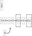
- Method 200 comprises blocs 110-160 in line with blocs 110-160 as described in Figure 2 .
- the hydraulic pumping system 1 comprises a flowmeter and the specific functional parameter fp is a functional flow of the centrifugal pump.
- functional flow we mean a flow of the centrifugal pump 2 at the functional point.
- the method 200 comprises a bloc 221 of acquiring the functional flow of the centrifugal pump 2 by a flowmeter and the specific functional parameter corresponds to the functional flow acquired by the flowmeter.
- the bloc 221 may be executed at any moment before the bloc 140 of computing the theoretical head HMT th .
- Method 300 comprises blocs 110-160 and 221 in line with blocs 110-160 and 221 as described in Figures 2 and 4 .
- the end-of-lines characteristics comprise a plurality of representations R.
- the plurality of representations R comprises a head/flow representation R H/f associating values of flow to values of head HMT and a NPSH r /flow representation R NPSHr/f associating values of flow to values of NPSH r .
- the bloc 140 of determining the theoretical head HMT th comprises a sub-bloc 341 of selecting a head value HMT of the head/flow representation R H/f based on the functional flow of the centrifugal pump 2 acquired in the bloc 221.
- the selected head HMT value may be the head value HMT of the head/flow representation R H/f associated to the same or to the closest flow value of the functional flow value.
- a functional speed ⁇ f associated to the functional flow is different from a specific speed ⁇ s associated to the head/flow representation R H/f
- all or part of the head/flow representation R H/f may be converted into the functional speed ⁇ f before selecting the head value in the head/flow representation R H/f .
- the flow can be considered proportional to the speed ⁇ of the centrifugal pump 2 and the head HMT can be considered proportional to the square of the speed ⁇ .
- the selected head HMT in the head/flow representation R H/f may correspond to the theoretical head HMT th .
- the bloc 160 of determining the aNPSH r value comprises a sub-bloc 361 of selecting a NPSH, value of the NPSH r /flow representation R NPSHr/f based on the functional flow of the centrifugal pump.
- the selected NPSH, value may be the NPSH, value of the NPSH r /flow representation R NFSHr/f associated to the same or to the closest flow value of the functional flow value.
- a functional speed ⁇ f associated to the functional flow is different from a specific speed ⁇ s associated to the NPSH r /flow representation R NPSHr/f
- all or part of the NPSH r /flow representation R NFSHr/f may be converted into the functional speed ⁇ f before selecting the NPSH, value in the NPSH r /flow representation R NPSHr/f .
- the flow can be considered proportional to the speed ⁇ of the centrifugal pump 2 and the NPSH, can be considered proportional to the square of the speed ⁇ .
- Method 400 which is an embodiment of the method 100 according to this disclose is illustrated in Figure 6 .
- Method 400 comprises blocs 110-160 in line with blocs 110-160 as described in Figure 2 .
- the specific functional parameter fp is a functional motor power of the centrifugal pump 2.
- functional motor power we mean a motor power of the centrifugal pump 2 at the functional point.
- the functional motor power may be obtained by reading the motor power of the centrifugal pump 2 at the functional point.
- the end-of-lines characteristics comprise a plurality of representations R.
- the plurality of representations R comprise a head/power representation R H/P associating values of motor power to values of head HMT and a NPSH r /power representation R NPSHr/P associating values of motor power to values of NPSH r .
- the bloc 140 of determining the theoretical head HMT th comprises a sub-bloc 441 of selecting a head value HMT of the head/power representation R H/P based on the functional motor power of the centrifugal pump 2.
- the selected head HMT value may be the head value HMT of the head/power representation R H/P associated to the same or to the closest motor power value of the functional motor power value.
- a functional speed ⁇ f associated to the functional motor power is different from a specific speed ⁇ s associated to the head/power representation R H/P
- all or part of the head/power representation R H/P may be converted into the functional speed ⁇ f before selecting the head value in the head/power representation R H/P .
- the motor power can be considered proportional to the cube of the speed ⁇ of the centrifugal pump 2 and the head HMT can be considered proportional to the square of the speed ⁇ .
- the selected head HMT in the head/power representation R H/P may correspond to the theoretical head HMT th .
- the bloc 160 of determining the aNPSH r value comprises a sub-bloc 461 of selecting a NPSH, value of the NPSH r /power representation R NPSHr/P based on the functional motor power of the centrifugal pump.
- the selected NPSH, value may be the NPSH, value of the NPSH r /power representation R NPSHr/P associating to the same or to the closest motor power value of the functional motor power value.
- a functional speed ⁇ f associated to the functional motor power is different from a specific speed ⁇ s associated to the NPSH r /power representation R NPSHr/P
- all or part of the NPSH r /power representation R NPSHr/P may be converted into the functional speed ⁇ f before selecting the NPSH, value in the NPSH r /power representation R NPSHr/P .
- the motor power can be considered proportional to the cube of the speed ⁇ of the centrifugal pump 2 and the NPSH, can be considered proportional to the square of the speed ⁇ .
- the aNPSH r value may be obtained by adding the selected NPSH, value selected in a representation R NPSHR/rp associating values of one of the reference parameter (flow or motor power respectively in methods 300 and 400) to NPSH, values and the head difference ⁇ H.
- Method 500 comprises blocs 110-160 in line with blocs 110-160 as described in Figure 2 .
- method 500 may be an embodiment of any of the methods 100 to 400 described above.
- the example method 500 comprises a bloc 570 of determining a Net Positive Suction Head Available value NPSH, based on the suction pressure Ps.
- NPSH Net Positive Suction Head Available value
- value we mean a pressure available at a suction flange of the centrifugal pump 2 for the functional point.
- the NPSH, value may be obtained based on the suction pressure Ps and on a vaporization pressure of the fluid.
- the method 500 also comprises a bloc 580 of triggering a cavitation alert when a difference between the NPSHa value and the aNPSH r value is below a predetermined threshold.
- a predetermined threshold As said above, when the NPSHa value is below the aNPSH r value, cavitation appears.
- the bloc 280 therefore allows preventing or alerting the pump user of cavitation.
- the threshold may correspond to 0.5 mH2O or may be comprised between 0.2 and 1 mH2O.
- the cavitation alert comprises several levels of alerts depending on the value of the difference between the NPSH, value and the aNPSH r value.
- a warning alert may be triggered when the difference between the NPSH, value and the aNPSH r value is below 0.5 water meter column (mH2O).
- an alarm alert may be triggered when the difference between the NPSH, value and the aNPSH r value is significantly equal to zero.
- a fault alert may be triggered when the difference between the NPSH, value and the aNPSH r value is below minus 0.1 water meter column mH2O.
- the specific speed ⁇ f of the centrifugal pump 2 may be decreased.
- each of the example methods presented hereby may comprise pumping, with the centrifugal pump 2, a fluid having a density higher than the density of water and/or comprising solids.
- the pumped fluid may comprise a density between 1 and 1.2 times the density of the water.
- the centrifugal pump 2 is associated to an identification number ID.
- each of the example methods described hereby may comprise storing the aNPSHr value along with the identification number ID of the centrifugal pump 2 into a memory of a data processing apparatus. Storing the aNPSHr value along with the identification number ID allows building statistics of the evolution of NPSH, values between different centrifugal pumps. For example, it may be built an average NPSH, value based on NPSHr values of centrifugal pumps at a determined time of life, the centrifugal pumps being produced by a same production line. The average NPSH r of centrifugal pumps built from different production lines may be compared to identify a problem on specific production lines. The average NPSH, value on a production line may also be used to study centrifugal pumps of this production line having a NPSH, value below the average value NPSH r .
Landscapes
- Engineering & Computer Science (AREA)
- Mechanical Engineering (AREA)
- General Engineering & Computer Science (AREA)
- Control Of Non-Positive-Displacement Pumps (AREA)
Claims (15)
- Procédé mis en oeuvre par ordinateur pour commander un système (1) de pompage hydraulique, le système (1) comprenant une pompe centrifuge (2) opérationnelle à un point fonctionnel, le procédé comprenant :- l'estimation (110) d'une pression d'aspiration (Ps) de la pompe centrifuge (2) représentant une pression à un point d'entrée de la pompe centrifuge (2) ;- l'estimation (120) d'une pression d'évacuation (Pd) de la pompe centrifuge (2) ; représentant une pression à un point de sortie de la pompe centrifuge (2) ;- le calcul (130) d'une hauteur manométrique actuelle (HMTp) de la pompe centrifuge (2) sur la base de la pression d'aspiration (Ps) et de la pression d'évacuation (Pd) ;- le fait de déterminer (140) une hauteur manométrique théorique (HMTth) sur la base d'une valeur d'un paramètre fonctionnel spécifique (fp) lié au point fonctionnel de la pompe centrifuge (2) dans le système (1) et sur des caractéristiques de fin de ligne de la pompe centrifuge (2), les caractéristiques de fin de ligne comprenant des paramètres associés à la pompe centrifuge (2) lorsqu'une telle pompe centrifuge (2) est sensiblement neuve ;- le calcul (150) d'une différence de hauteur (∂H) entre la hauteur manométrique actuelle (HMTp) et la hauteur manométrique théorique (HMTth) ; et- le fait de déterminer (160), pour le point fonctionnel, une valeur de hauteur d'aspiration positive nette requise adaptée, la valeur aNPSHr, de la pompe centrifuge (2), pour éviter la cavitation de la pompe centrifuge, sur la base de la différence de hauteur (∂H) et des caractéristiques de fin de ligne.
- Procédé selon la revendication 1, dans lequel le paramètre fonctionnel spécifique (fp) correspond à une puissance motrice de la pompe centrifuge (2) ou à un débit de la pompe centrifuge (2).
- Procédé selon l'une quelconque des revendications précédentes, dans lequel les caractéristiques de fin de ligne comprennent une pluralité de représentations (R), chaque représentation étant associée à une vitesse spécifique (ωs) de la pompe centrifuge (2), chaque représentation (R) associant des valeurs d'un premier paramètre de référence respectif (rp1) à des valeurs d'un second paramètre de référence respectif (rp2), le premier paramètre de référence respectif différant du second paramètre de référence respectif.
- Procédé selon la revendication précédente, dans lequel l'un des premier ou second paramètres de référence correspond au paramètre fonctionnel spécifique.
- Procédé selon l'une quelconque des revendications 3 ou 4, dans lequel les premier ou second paramètres de référence correspondent à l'un parmi une puissance motrice de la pompe centrifuge (2), un débit de la pompe centrifuge (2), une hauteur d'aspiration positive nette requise, NPSHr, de la pompe centrifuge (2) ou une hauteur manométrique (HMT) de la pompe centrifuge (2).
- Procédé selon l'une quelconque des revendications 3 à 5, dans lequel le paramètre fonctionnel spécifique (fp) est un débit fonctionnel de la pompe centrifuge (2), la pluralité de représentations (R) comprenant une représentation hauteur/débit (RH/f) associant des valeurs de débit à des valeurs de hauteur manométrique (HMT), et une représentation NPSHr/débit (RNPSHr/f) associant des valeurs de débit à des valeurs de NPSHr,dans lequel le fait de déterminer (140) la hauteur manométrique théorique (HMTth) comprend la sélection (341) d'une valeur de hauteur manométrique (HMT) de la représentation hauteur/débit (RH/f) sur la base du débit fonctionnel de la pompe centrifuge ; etdans lequel le fait de déterminer (160) la valeur aNPSHr comprend la sélection (161) d'une valeur NPSHr de la représentation NPSHr/débit (RNPSHr/f) sur la base du débit fonctionnel de la pompe centrifuge.
- Procédé selon l'une quelconque des revendications 3 à 5, dans lequel le paramètre fonctionnel spécifique est une puissance motrice fonctionnelle de la pompe centrifuge (2), la pluralité de représentations (R) comprenant une représentation hauteur/puissance (RH/P) associant des valeurs de puissance motrice à des valeurs de hauteur manométrique (HMT) et une représentation NPSHr/puissance (RNPSHr/P) associant des valeurs de puissance motrice à des valeurs de NPSHr,dans lequel le fait de déterminer (140) la hauteur manométrique théorique (HMTth) comprend la sélection (141) d'une valeur de hauteur manométrique (HMT) de la représentation hauteur/puissance (RH/P) sur la base de la puissance motrice fonctionnelle de la pompe centrifuge (2) ; etdans lequel le fait de déterminer (160) la valeur aNPSHr comprend la sélection (161) d'une valeur NPSH, de la représentation NPSHr/puissance (RNPSHr/P) sur la base de la puissance motrice fonctionnelle de la pompe centrifuge (2).
- Procédé selon l'une quelconque des revendications 6 ou 7, dans lequel la valeur aNPSHr est obtenue en additionnant la valeur NPSH, sélectionnée et la différence de hauteur (9H).
- Procédé selon l'une quelconque des revendications précédentes, dans lequel le paramètre fonctionnel spécifique (fp) est un débit fonctionnel de la pompe centrifuge (2) et dans lequel le procédé comprend également :- l'acquisition du débit fonctionnel de la pompe centrifuge (2) par un débitmètre.
- Procédé selon l'une quelconque des revendications précédentes, dans lequel le procédé comprend également :- le pompage, avec la pompe centrifuge (2), d'un fluide présentant une densité supérieure à la densité de l'eau, et/ou- le pompage, avec la pompe centrifuge (2), d'un fluide comprenant des solides.
- Procédé selon l'une quelconque des revendications précédentes, dans lequel le procédé comprend également :- le fait de déterminer (270) une valeur disponible de hauteur d'aspiration positive nette, la valeur NPSHa, sur la base de la pression d'aspiration (Ps) ; et- le déclenchement (280) d'une alerte de cavitation lorsqu'une différence entre la valeur NPSHa et la valeur aNPSHr est inférieure à un seuil prédéterminé.
- Procédé selon la revendication précédente, dans lequel l'alerte de cavitation comprend plusieurs niveaux d'alertes en fonction de la valeur de la différence entre la valeur NPSHa et la valeur aNPSHr.
- Procédé selon l'une quelconque des revendications précédentes, dans lequel un numéro d'identification (ID) est associé à la pompe centrifuge (2) et le procédé comprend également :- le stockage de la valeur aNPSHr avec le numéro d'identification (ID) de la pompe centrifuge (2) dans une mémoire d'un appareil de traitement de données (5).
- Support de stockage lisible par ordinateur comprenant des instructions qui, lorsqu'elles sont exécutées par un processeur (PROC), amènent le processeur à réaliser le procédé selon l'une quelconque des revendications de procédé ci-dessus.
- Appareil de traitement de données (5) comprenant un processeur adapté pour commander un système de pompage hydraulique (1) selon l'une quelconque des revendications de procédé ci-dessus.
Priority Applications (4)
| Application Number | Priority Date | Filing Date | Title |
|---|---|---|---|
| EP20306374.8A EP4001652B1 (fr) | 2020-11-13 | 2020-11-13 | Fonctionnement de pompe centrifuge |
| ES20306374T ES2963631T3 (es) | 2020-11-13 | 2020-11-13 | Funcionamiento de una bomba centrífuga |
| US17/522,996 US11994150B2 (en) | 2020-11-13 | 2021-11-10 | Centrifugal pump operation |
| CN202111338536.0A CN114483600B (zh) | 2020-11-13 | 2021-11-12 | 离心泵操作 |
Applications Claiming Priority (1)
| Application Number | Priority Date | Filing Date | Title |
|---|---|---|---|
| EP20306374.8A EP4001652B1 (fr) | 2020-11-13 | 2020-11-13 | Fonctionnement de pompe centrifuge |
Publications (2)
| Publication Number | Publication Date |
|---|---|
| EP4001652A1 EP4001652A1 (fr) | 2022-05-25 |
| EP4001652B1 true EP4001652B1 (fr) | 2023-08-16 |
Family
ID=74129974
Family Applications (1)
| Application Number | Title | Priority Date | Filing Date |
|---|---|---|---|
| EP20306374.8A Active EP4001652B1 (fr) | 2020-11-13 | 2020-11-13 | Fonctionnement de pompe centrifuge |
Country Status (4)
| Country | Link |
|---|---|
| US (1) | US11994150B2 (fr) |
| EP (1) | EP4001652B1 (fr) |
| CN (1) | CN114483600B (fr) |
| ES (1) | ES2963631T3 (fr) |
Families Citing this family (1)
| Publication number | Priority date | Publication date | Assignee | Title |
|---|---|---|---|---|
| JP7729284B2 (ja) * | 2022-08-05 | 2025-08-26 | 横河電機株式会社 | 検知装置、検知方法及び検知システム |
Family Cites Families (13)
| Publication number | Priority date | Publication date | Assignee | Title |
|---|---|---|---|---|
| JP2000110769A (ja) * | 1998-10-02 | 2000-04-18 | Toshiba Corp | 可変速ポンプの速度制御装置 |
| US6464464B2 (en) * | 1999-03-24 | 2002-10-15 | Itt Manufacturing Enterprises, Inc. | Apparatus and method for controlling a pump system |
| AU8001100A (en) * | 1999-10-06 | 2001-05-10 | Vaughan Co., Inc. | Centrifugal pump improvements |
| US6663349B1 (en) * | 2001-03-02 | 2003-12-16 | Reliance Electric Technologies, Llc | System and method for controlling pump cavitation and blockage |
| US7168924B2 (en) * | 2002-09-27 | 2007-01-30 | Unico, Inc. | Rod pump control system including parameter estimator |
| WO2005080798A1 (fr) * | 2004-02-23 | 2005-09-01 | Mitsubishi Heavy Industries, Ltd. | Système de pompe d'alimentation en eau |
| FR2931213A1 (fr) * | 2008-05-16 | 2009-11-20 | Air Liquide | Dispositif et procede de pompage d'un fluide cryogenique |
| JP2011185190A (ja) * | 2010-03-10 | 2011-09-22 | Ebara Corp | 制御装置一体型モータポンプ |
| GB2482861B (en) * | 2010-07-30 | 2014-12-17 | Hivis Pumps As | Pump/motor assembly |
| US9127678B2 (en) * | 2011-04-06 | 2015-09-08 | Field Intelligence, Inc. | Fast-response pump monitoring and in-situ pump data recording system |
| JP5714472B2 (ja) * | 2011-11-30 | 2015-05-07 | 株式会社日立製作所 | 製品情報管理装置、方法、及びプログラム |
| DE102017203990A1 (de) * | 2017-03-10 | 2018-09-13 | KSB SE & Co. KGaA | Verfahren zur Regelung der Drehzahl einer Kreiselpumpe |
| FR3072737B1 (fr) * | 2017-10-25 | 2021-09-24 | Suez Groupe | Procede et dispositif de maintien en condition operationnelle d'un systeme de pompage |
-
2020
- 2020-11-13 EP EP20306374.8A patent/EP4001652B1/fr active Active
- 2020-11-13 ES ES20306374T patent/ES2963631T3/es active Active
-
2021
- 2021-11-10 US US17/522,996 patent/US11994150B2/en active Active
- 2021-11-12 CN CN202111338536.0A patent/CN114483600B/zh active Active
Also Published As
| Publication number | Publication date |
|---|---|
| EP4001652A1 (fr) | 2022-05-25 |
| US20220154732A1 (en) | 2022-05-19 |
| ES2963631T3 (es) | 2024-04-01 |
| CN114483600A (zh) | 2022-05-13 |
| US11994150B2 (en) | 2024-05-28 |
| CN114483600B (zh) | 2026-04-24 |
Similar Documents
| Publication | Publication Date | Title |
|---|---|---|
| EP2196678B1 (fr) | Procédé et système pour détecter la cavitation d'une pompe et convertisseur de fréquence | |
| EP2610693B1 (fr) | Procédé et appareil pour optimiser l'efficacité énergétique dans un système de pompage | |
| US10197060B2 (en) | Gas lock resolution during operation of an electric submersible pump | |
| US20070183902A1 (en) | Anti-entrapment and anti-dead head function | |
| US9886018B2 (en) | Pump control for operation on a variable pressure force main | |
| EP4001652B1 (fr) | Fonctionnement de pompe centrifuge | |
| JP5921160B2 (ja) | ポンプの制御方法及びその制御装置 | |
| US12044239B2 (en) | Submersible pump system, information processing device, and computer program | |
| JPWO2021029387A5 (fr) | ||
| US11846293B2 (en) | Method for operating a pump | |
| JP6750058B1 (ja) | 給水装置 | |
| EP3199813B1 (fr) | Procédé de commande de chargement/déchargement pour système de compresseur | |
| US20030221722A1 (en) | Method of damping surges in a liquid system | |
| CN107013444A (zh) | 用于压缩机系统的控制方法及设备 | |
| JP7262742B2 (ja) | 給水装置 | |
| JP6591391B2 (ja) | 井戸ポンプ装置 | |
| JP2923249B2 (ja) | 水道用給液装置 | |
| CA3057529C (fr) | Commandes adaptatives de niveau d'eau pour applications de vidage ou de remplissage d'eau | |
| CN119373721A (zh) | 一种智能循环水泵及其控制方法 | |
| CN117984666A (zh) | 一种墨泵转速自适应控制方法、设备及存储介质 | |
| CN117267143A (zh) | 一种潜水泵用控制保护系统及方法 | |
| CN118856538A (zh) | 用于控制空调器的方法及装置、空调器、冷凝水排放装置 | |
| JPH02218487A (ja) | ポンプ台数制御装置 | |
| AU2005266837A1 (en) | Pump control system |
Legal Events
| Date | Code | Title | Description |
|---|---|---|---|
| PUAI | Public reference made under article 153(3) epc to a published international application that has entered the european phase |
Free format text: ORIGINAL CODE: 0009012 |
|
| STAA | Information on the status of an ep patent application or granted ep patent |
Free format text: STATUS: REQUEST FOR EXAMINATION WAS MADE |
|
| 17P | Request for examination filed |
Effective date: 20211018 |
|
| AK | Designated contracting states |
Kind code of ref document: A1 Designated state(s): AL AT BE BG CH CY CZ DE DK EE ES FI FR GB GR HR HU IE IS IT LI LT LU LV MC MK MT NL NO PL PT RO RS SE SI SK SM TR |
|
| RIC1 | Information provided on ipc code assigned before grant |
Ipc: F04D 29/66 20060101ALI20230125BHEP Ipc: F04D 15/00 20060101ALI20230125BHEP Ipc: F04D 1/00 20060101AFI20230125BHEP |
|
| GRAP | Despatch of communication of intention to grant a patent |
Free format text: ORIGINAL CODE: EPIDOSNIGR1 |
|
| STAA | Information on the status of an ep patent application or granted ep patent |
Free format text: STATUS: GRANT OF PATENT IS INTENDED |
|
| INTG | Intention to grant announced |
Effective date: 20230306 |
|
| GRAS | Grant fee paid |
Free format text: ORIGINAL CODE: EPIDOSNIGR3 |
|
| GRAA | (expected) grant |
Free format text: ORIGINAL CODE: 0009210 |
|
| STAA | Information on the status of an ep patent application or granted ep patent |
Free format text: STATUS: THE PATENT HAS BEEN GRANTED |
|
| AK | Designated contracting states |
Kind code of ref document: B1 Designated state(s): AL AT BE BG CH CY CZ DE DK EE ES FI FR GB GR HR HU IE IS IT LI LT LU LV MC MK MT NL NO PL PT RO RS SE SI SK SM TR |
|
| REG | Reference to a national code |
Ref country code: CH Ref legal event code: EP |
|
| REG | Reference to a national code |
Ref country code: DE Ref legal event code: R096 Ref document number: 602020015801 Country of ref document: DE |
|
| REG | Reference to a national code |
Ref country code: IE Ref legal event code: FG4D |
|
| REG | Reference to a national code |
Ref country code: LT Ref legal event code: MG9D |
|
| REG | Reference to a national code |
Ref country code: NL Ref legal event code: MP Effective date: 20230816 |
|
| REG | Reference to a national code |
Ref country code: AT Ref legal event code: MK05 Ref document number: 1600301 Country of ref document: AT Kind code of ref document: T Effective date: 20230816 |
|
| PG25 | Lapsed in a contracting state [announced via postgrant information from national office to epo] |
Ref country code: GR Free format text: LAPSE BECAUSE OF FAILURE TO SUBMIT A TRANSLATION OF THE DESCRIPTION OR TO PAY THE FEE WITHIN THE PRESCRIBED TIME-LIMIT Effective date: 20231117 |
|
| PG25 | Lapsed in a contracting state [announced via postgrant information from national office to epo] |
Ref country code: IS Free format text: LAPSE BECAUSE OF FAILURE TO SUBMIT A TRANSLATION OF THE DESCRIPTION OR TO PAY THE FEE WITHIN THE PRESCRIBED TIME-LIMIT Effective date: 20231216 |
|
| PG25 | Lapsed in a contracting state [announced via postgrant information from national office to epo] |
Ref country code: SE Free format text: LAPSE BECAUSE OF FAILURE TO SUBMIT A TRANSLATION OF THE DESCRIPTION OR TO PAY THE FEE WITHIN THE PRESCRIBED TIME-LIMIT Effective date: 20230816 Ref country code: RS Free format text: LAPSE BECAUSE OF FAILURE TO SUBMIT A TRANSLATION OF THE DESCRIPTION OR TO PAY THE FEE WITHIN THE PRESCRIBED TIME-LIMIT Effective date: 20230816 Ref country code: PT Free format text: LAPSE BECAUSE OF FAILURE TO SUBMIT A TRANSLATION OF THE DESCRIPTION OR TO PAY THE FEE WITHIN THE PRESCRIBED TIME-LIMIT Effective date: 20231218 Ref country code: NO Free format text: LAPSE BECAUSE OF FAILURE TO SUBMIT A TRANSLATION OF THE DESCRIPTION OR TO PAY THE FEE WITHIN THE PRESCRIBED TIME-LIMIT Effective date: 20231116 Ref country code: NL Free format text: LAPSE BECAUSE OF FAILURE TO SUBMIT A TRANSLATION OF THE DESCRIPTION OR TO PAY THE FEE WITHIN THE PRESCRIBED TIME-LIMIT Effective date: 20230816 Ref country code: LV Free format text: LAPSE BECAUSE OF FAILURE TO SUBMIT A TRANSLATION OF THE DESCRIPTION OR TO PAY THE FEE WITHIN THE PRESCRIBED TIME-LIMIT Effective date: 20230816 Ref country code: LT Free format text: LAPSE BECAUSE OF FAILURE TO SUBMIT A TRANSLATION OF THE DESCRIPTION OR TO PAY THE FEE WITHIN THE PRESCRIBED TIME-LIMIT Effective date: 20230816 Ref country code: IS Free format text: LAPSE BECAUSE OF FAILURE TO SUBMIT A TRANSLATION OF THE DESCRIPTION OR TO PAY THE FEE WITHIN THE PRESCRIBED TIME-LIMIT Effective date: 20231216 Ref country code: HR Free format text: LAPSE BECAUSE OF FAILURE TO SUBMIT A TRANSLATION OF THE DESCRIPTION OR TO PAY THE FEE WITHIN THE PRESCRIBED TIME-LIMIT Effective date: 20230816 Ref country code: GR Free format text: LAPSE BECAUSE OF FAILURE TO SUBMIT A TRANSLATION OF THE DESCRIPTION OR TO PAY THE FEE WITHIN THE PRESCRIBED TIME-LIMIT Effective date: 20231117 Ref country code: FI Free format text: LAPSE BECAUSE OF FAILURE TO SUBMIT A TRANSLATION OF THE DESCRIPTION OR TO PAY THE FEE WITHIN THE PRESCRIBED TIME-LIMIT Effective date: 20230816 Ref country code: AT Free format text: LAPSE BECAUSE OF FAILURE TO SUBMIT A TRANSLATION OF THE DESCRIPTION OR TO PAY THE FEE WITHIN THE PRESCRIBED TIME-LIMIT Effective date: 20230816 |
|
| PG25 | Lapsed in a contracting state [announced via postgrant information from national office to epo] |
Ref country code: PL Free format text: LAPSE BECAUSE OF FAILURE TO SUBMIT A TRANSLATION OF THE DESCRIPTION OR TO PAY THE FEE WITHIN THE PRESCRIBED TIME-LIMIT Effective date: 20230816 |
|
| REG | Reference to a national code |
Ref country code: ES Ref legal event code: FG2A Ref document number: 2963631 Country of ref document: ES Kind code of ref document: T3 Effective date: 20240401 |
|
| PG25 | Lapsed in a contracting state [announced via postgrant information from national office to epo] |
Ref country code: SM Free format text: LAPSE BECAUSE OF FAILURE TO SUBMIT A TRANSLATION OF THE DESCRIPTION OR TO PAY THE FEE WITHIN THE PRESCRIBED TIME-LIMIT Effective date: 20230816 Ref country code: RO Free format text: LAPSE BECAUSE OF FAILURE TO SUBMIT A TRANSLATION OF THE DESCRIPTION OR TO PAY THE FEE WITHIN THE PRESCRIBED TIME-LIMIT Effective date: 20230816 Ref country code: EE Free format text: LAPSE BECAUSE OF FAILURE TO SUBMIT A TRANSLATION OF THE DESCRIPTION OR TO PAY THE FEE WITHIN THE PRESCRIBED TIME-LIMIT Effective date: 20230816 Ref country code: DK Free format text: LAPSE BECAUSE OF FAILURE TO SUBMIT A TRANSLATION OF THE DESCRIPTION OR TO PAY THE FEE WITHIN THE PRESCRIBED TIME-LIMIT Effective date: 20230816 Ref country code: CZ Free format text: LAPSE BECAUSE OF FAILURE TO SUBMIT A TRANSLATION OF THE DESCRIPTION OR TO PAY THE FEE WITHIN THE PRESCRIBED TIME-LIMIT Effective date: 20230816 Ref country code: SK Free format text: LAPSE BECAUSE OF FAILURE TO SUBMIT A TRANSLATION OF THE DESCRIPTION OR TO PAY THE FEE WITHIN THE PRESCRIBED TIME-LIMIT Effective date: 20230816 |
|
| REG | Reference to a national code |
Ref country code: DE Ref legal event code: R097 Ref document number: 602020015801 Country of ref document: DE |
|
| PLBE | No opposition filed within time limit |
Free format text: ORIGINAL CODE: 0009261 |
|
| STAA | Information on the status of an ep patent application or granted ep patent |
Free format text: STATUS: NO OPPOSITION FILED WITHIN TIME LIMIT |
|
| REG | Reference to a national code |
Ref country code: CH Ref legal event code: PL |
|
| PG25 | Lapsed in a contracting state [announced via postgrant information from national office to epo] |
Ref country code: MC Free format text: LAPSE BECAUSE OF FAILURE TO SUBMIT A TRANSLATION OF THE DESCRIPTION OR TO PAY THE FEE WITHIN THE PRESCRIBED TIME-LIMIT Effective date: 20230816 |
|
| PG25 | Lapsed in a contracting state [announced via postgrant information from national office to epo] |
Ref country code: LU Free format text: LAPSE BECAUSE OF NON-PAYMENT OF DUE FEES Effective date: 20231113 |
|
| PG25 | Lapsed in a contracting state [announced via postgrant information from national office to epo] |
Ref country code: CH Free format text: LAPSE BECAUSE OF NON-PAYMENT OF DUE FEES Effective date: 20231130 |
|
| 26N | No opposition filed |
Effective date: 20240517 |
|
| PG25 | Lapsed in a contracting state [announced via postgrant information from national office to epo] |
Ref country code: MC Free format text: LAPSE BECAUSE OF FAILURE TO SUBMIT A TRANSLATION OF THE DESCRIPTION OR TO PAY THE FEE WITHIN THE PRESCRIBED TIME-LIMIT Effective date: 20230816 Ref country code: LU Free format text: LAPSE BECAUSE OF NON-PAYMENT OF DUE FEES Effective date: 20231113 Ref country code: IT Free format text: LAPSE BECAUSE OF NON-PAYMENT OF DUE FEES Effective date: 20231113 Ref country code: CH Free format text: LAPSE BECAUSE OF NON-PAYMENT OF DUE FEES Effective date: 20231130 Ref country code: SI Free format text: LAPSE BECAUSE OF FAILURE TO SUBMIT A TRANSLATION OF THE DESCRIPTION OR TO PAY THE FEE WITHIN THE PRESCRIBED TIME-LIMIT Effective date: 20230816 |
|
| REG | Reference to a national code |
Ref country code: BE Ref legal event code: MM Effective date: 20231130 |
|
| REG | Reference to a national code |
Ref country code: IE Ref legal event code: MM4A |
|
| PG25 | Lapsed in a contracting state [announced via postgrant information from national office to epo] |
Ref country code: IE Free format text: LAPSE BECAUSE OF NON-PAYMENT OF DUE FEES Effective date: 20231113 |
|
| PG25 | Lapsed in a contracting state [announced via postgrant information from national office to epo] |
Ref country code: BE Free format text: LAPSE BECAUSE OF NON-PAYMENT OF DUE FEES Effective date: 20231130 |
|
| PG25 | Lapsed in a contracting state [announced via postgrant information from national office to epo] |
Ref country code: IE Free format text: LAPSE BECAUSE OF NON-PAYMENT OF DUE FEES Effective date: 20231113 Ref country code: BE Free format text: LAPSE BECAUSE OF NON-PAYMENT OF DUE FEES Effective date: 20231130 |
|
| PG25 | Lapsed in a contracting state [announced via postgrant information from national office to epo] |
Ref country code: BG Free format text: LAPSE BECAUSE OF FAILURE TO SUBMIT A TRANSLATION OF THE DESCRIPTION OR TO PAY THE FEE WITHIN THE PRESCRIBED TIME-LIMIT Effective date: 20230816 |
|
| PG25 | Lapsed in a contracting state [announced via postgrant information from national office to epo] |
Ref country code: BG Free format text: LAPSE BECAUSE OF FAILURE TO SUBMIT A TRANSLATION OF THE DESCRIPTION OR TO PAY THE FEE WITHIN THE PRESCRIBED TIME-LIMIT Effective date: 20230816 |
|
| PG25 | Lapsed in a contracting state [announced via postgrant information from national office to epo] |
Ref country code: IT Free format text: LAPSE BECAUSE OF NON-PAYMENT OF DUE FEES Effective date: 20231113 |
|
| PGFP | Annual fee paid to national office [announced via postgrant information from national office to epo] |
Ref country code: IT Payment date: 20241125 Year of fee payment: 5 Ref country code: ES Payment date: 20241218 Year of fee payment: 5 |
|
| PGRI | Patent reinstated in contracting state [announced from national office to epo] |
Ref country code: IT Effective date: 20231130 |
|
| PG25 | Lapsed in a contracting state [announced via postgrant information from national office to epo] |
Ref country code: IT Free format text: LAPSE BECAUSE OF NON-PAYMENT OF DUE FEES Effective date: 20231113 |
|
| PGRI | Patent reinstated in contracting state [announced from national office to epo] |
Ref country code: IT Effective date: 20231130 |
|
| PG25 | Lapsed in a contracting state [announced via postgrant information from national office to epo] |
Ref country code: CY Free format text: LAPSE BECAUSE OF FAILURE TO SUBMIT A TRANSLATION OF THE DESCRIPTION OR TO PAY THE FEE WITHIN THE PRESCRIBED TIME-LIMIT; INVALID AB INITIO Effective date: 20201113 |
|
| PG25 | Lapsed in a contracting state [announced via postgrant information from national office to epo] |
Ref country code: HU Free format text: LAPSE BECAUSE OF FAILURE TO SUBMIT A TRANSLATION OF THE DESCRIPTION OR TO PAY THE FEE WITHIN THE PRESCRIBED TIME-LIMIT; INVALID AB INITIO Effective date: 20201113 |
|
| PG25 | Lapsed in a contracting state [announced via postgrant information from national office to epo] |
Ref country code: TR Free format text: LAPSE BECAUSE OF FAILURE TO SUBMIT A TRANSLATION OF THE DESCRIPTION OR TO PAY THE FEE WITHIN THE PRESCRIBED TIME-LIMIT Effective date: 20230816 |
|
| PGFP | Annual fee paid to national office [announced via postgrant information from national office to epo] |
Ref country code: DE Payment date: 20251126 Year of fee payment: 6 |
|
| PGFP | Annual fee paid to national office [announced via postgrant information from national office to epo] |
Ref country code: GB Payment date: 20251125 Year of fee payment: 6 |
|
| PGFP | Annual fee paid to national office [announced via postgrant information from national office to epo] |
Ref country code: FR Payment date: 20251124 Year of fee payment: 6 |