EP4001724A1 - Dispositif de raccordement pour composants guidant des milieux - Google Patents
Dispositif de raccordement pour composants guidant des milieux Download PDFInfo
- Publication number
- EP4001724A1 EP4001724A1 EP20209557.6A EP20209557A EP4001724A1 EP 4001724 A1 EP4001724 A1 EP 4001724A1 EP 20209557 A EP20209557 A EP 20209557A EP 4001724 A1 EP4001724 A1 EP 4001724A1
- Authority
- EP
- European Patent Office
- Prior art keywords
- media
- carrying component
- section
- securing
- connection
- Prior art date
- Legal status (The legal status is an assumption and is not a legal conclusion. Google has not performed a legal analysis and makes no representation as to the accuracy of the status listed.)
- Granted
Links
Images


Classifications
-
- F—MECHANICAL ENGINEERING; LIGHTING; HEATING; WEAPONS; BLASTING
- F16—ENGINEERING ELEMENTS AND UNITS; GENERAL MEASURES FOR PRODUCING AND MAINTAINING EFFECTIVE FUNCTIONING OF MACHINES OR INSTALLATIONS; THERMAL INSULATION IN GENERAL
- F16L—PIPES; JOINTS OR FITTINGS FOR PIPES; SUPPORTS FOR PIPES, CABLES OR PROTECTIVE TUBING; MEANS FOR THERMAL INSULATION IN GENERAL
- F16L37/00—Couplings of the quick-acting type
- F16L37/08—Couplings of the quick-acting type in which the connection between abutting or axially overlapping ends is maintained by locking members
- F16L37/084—Couplings of the quick-acting type in which the connection between abutting or axially overlapping ends is maintained by locking members combined with automatic locking
- F16L37/088—Couplings of the quick-acting type in which the connection between abutting or axially overlapping ends is maintained by locking members combined with automatic locking by means of a split elastic ring
-
- F—MECHANICAL ENGINEERING; LIGHTING; HEATING; WEAPONS; BLASTING
- F16—ENGINEERING ELEMENTS AND UNITS; GENERAL MEASURES FOR PRODUCING AND MAINTAINING EFFECTIVE FUNCTIONING OF MACHINES OR INSTALLATIONS; THERMAL INSULATION IN GENERAL
- F16L—PIPES; JOINTS OR FITTINGS FOR PIPES; SUPPORTS FOR PIPES, CABLES OR PROTECTIVE TUBING; MEANS FOR THERMAL INSULATION IN GENERAL
- F16L37/00—Couplings of the quick-acting type
- F16L37/08—Couplings of the quick-acting type in which the connection between abutting or axially overlapping ends is maintained by locking members
- F16L37/084—Couplings of the quick-acting type in which the connection between abutting or axially overlapping ends is maintained by locking members combined with automatic locking
- F16L37/088—Couplings of the quick-acting type in which the connection between abutting or axially overlapping ends is maintained by locking members combined with automatic locking by means of a split elastic ring
- F16L37/0887—Couplings of the quick-acting type in which the connection between abutting or axially overlapping ends is maintained by locking members combined with automatic locking by means of a split elastic ring with an axially movable separate member for releasing the coupling
Definitions
- the invention relates to a connecting device for media-carrying components, comprising a first media-carrying component with an end section with an external thread and a cylindrical inner shell and a second media-carrying component with an end connection section for connection to the first media-carrying component.
- the invention further relates to a connection device for connection to a first media-carrying component and a method for releasing elements of the connection device.
- Media-carrying components e.g. B. of pipes for the fresh water supply in buildings
- Screw connections are known in which a second media-carrying component (fitting, fitting, pipe, etc.) with an internal thread is screwed onto a first media-carrying component (fitting, fitting, pipe, etc.) with an external thread.
- the seal is often made with the help of hemp, which is wrapped around the external thread before screwing.
- Alternatives to hemp are sealing tapes or liquid plastics. If screwed connections are made correctly, they are permanently tight and can withstand high pressures.
- connection will not be completely correct, so the tightness is not guaranteed if the screw connection is not tightened sufficiently, if too much hemp is used or if it is pushed in front of you by the component with the internal thread when screwing. Hemp in compounds for drinking water also poses problems for drinking water hygiene because hemp can form a breeding ground for bacteria. In addition are used to produce the screw connection tools such. B. wrenches or open-end wrenches that require a certain amount of space. This can be problematic in tight spaces.
- plug-in connections in which a second media-carrying component is plugged into a first media-carrying component by means of a substantially axial plug-in movement.
- a connection section of the second media-carrying element snaps into a corresponding section of the first resilient element during the plugging process, after which the connection is sealed (by a suitable sealing element) and secured axially.
- Plug connections can thus be easily produced. However, they cannot usually be solved non-destructively. Replacing the connection results in a correspondingly high outlay.
- the object of the invention is to create a connecting device that belongs to the technical field mentioned at the outset, which can be manufactured easily and safely and can be released again without destroying it.
- the connecting device also includes a locking piece with an internal thread for screwing onto the external thread of the first media-carrying component.
- the securing piece and the second media-carrying component are designed in such a way that the second media-carrying component can be sealingly connected to the first media-carrying component with the screwed-on securing piece by means of a plug-in process, the connection being secured by the elastic element.
- distal refers to an arrangement towards the free end of a component
- proximal refers to an arrangement in the opposite direction.
- the securing section is therefore arranged behind the sealing section, starting from the free end of the second media-carrying component, for example, so the order is free end—sealing section—securing section.
- the elastic element is in particular a resilient element.
- a snapping, clicking or latching takes place, with the elastic element (fully or partially) relaxing abruptly in order to change from a first configuration to a second configuration.
- the second configuration is such that the connection is secured axially by the elastic element.
- the securing takes place in particular between the second media-carrying component and the securing piece screwed onto the first media-carrying component.
- connection device can be produced quickly and easily by the (axial) plug-in process. This does not even require a direct view of the connection point. However, by loosening the screw connection between the securing piece and the first media-carrying component, it can be loosened again in a simple and non-destructive manner, with it not even being necessary to turn one of the media-carrying components.
- the elements for the axial securing on the one hand and for the sealing against the guided medium are functionally clearly separated and can be optimized with regard to their function.
- connection device is basically suitable for various media-carrying components, e.g. B. for water, other liquids or gases suitable. It is particularly suitable for the fresh water supply, especially for floor installations.
- a connecting device can be used between a floor distributor and the outgoing lines.
- the first media-carrying component and the second media-carrying component can be z. B. be distributor connections, fittings or pipe ends.
- the connecting device can easily be manufactured with different dimensions. For example, it can be adapted to the nominal diameter of a distribution line (e.g. DN 10/15/20).
- the plug-in connection can be implemented in such a way that a clearly audible noise is generated when it snaps in, clicks in or engages, which the fitter can hear as a signal for the Production of the sealing connection and the axial securing is used.
- the elements between which the plug-in connection is made can be designed to be essentially rotationally symmetrical within the scope of the connection device according to the invention, so that even after the plug-in connection has been made, the second media-carrying component can still be rotated about its longitudinal axis relative to the first media-carrying component without the connection being broken loosens or leaks.
- the connecting device can be made of different materials, e.g. B. made of gunmetal, brass, stainless steel or in the EP 2 014 964 B1 (R. Nussbaum AG) specified alloy.
- connection ie the first media-carrying component, the second media-carrying component and the securing piece, can be made from the same material or from different materials.
- connection device also includes a locking piece with an internal thread for screwing onto the external thread of the first media-carrying component.
- the securing piece and the second media-carrying component are designed in such a way that the second media-carrying component can be sealingly connected to the first media-carrying component with the screwed-on securing piece by means of a plug-in process, the connection being secured by the elastic element.
- connection To establish the connection, the securing piece is first screwed onto the external thread of the first media-carrying component. The connection can then be established by a plug-in process.
- the securing section of the second media-carrying component preferably comprises a receiving groove and, as an elastic element, a snap ring arranged in the receiving groove.
- a snap ring made of an elastic material, e.g. B. spring steel, bent, open, essentially circular ring understood.
- connection section of the second media-carrying component When the connection section of the second media-carrying component is inserted (slided in), the snap ring is compressed by radial forces; when it snaps in, clicks in or snaps in, it suddenly relaxes (at least partially) in order to secure the second media-carrying component axially on the first media-carrying component.
- the securing piece advantageously has a tapered inlet for the securing section of the second media-carrying component and a receiving groove for the snap ring of the second media-carrying component in its pushed-in position.
- the tapered run-in allows for gradual compression of the snap ring, keeping insertion forces in check.
- the (inside) receiving groove of the securing piece interacts with its (outside) receiving groove in order to receive the (fully or partially) relaxed snap ring.
- the snap ring secures the connection axially because it prevents an axial movement of the second media-carrying component to the securing piece (and thus to the first media-carrying component screwed to it).
- the receiving groove of the securing piece directly adjoins the incoming inlet. This results in a defined locking process and the axial play is minimized.
- the connecting device can also be designed to be compact in the axial direction.
- the tapering inlet of the locking piece has a first taper value in a first section facing away from the receiving groove and has a second taper value in a second section facing the receiving groove, the second taper value being greater than the first taper value.
- the taper value denotes the value of the cone taper, defined as the ratio between the diameter difference and the axial distance. In the case of a tapering section, a high value thus corresponds to a faster decrease in the inner diameter than a low value.
- the geometry mentioned means that the snap ring is initially pre-centered when it is pushed in, with only slight radial forces acting on it. This prevents the snap ring from being clamped between the securing piece and the second media-carrying component, which would make further insertion impossible. Once pre-centering has occurred, higher radial forces act on and compress the snap ring due to the higher taper value in the second section.
- the first section and the second section can directly adjoin one another or be spaced apart by an intermediate section.
- the first section does not have to be directly adjacent to the free end of the securing piece on the inlet side, and the second section does not have to be directly adjacent to the receiving groove of the securing piece.
- the receiving groove of the second media-carrying component and the receiving groove of the securing piece advantageously together form a circumferential receptacle with a symmetrically oval cross-section.
- Such a cross-section can accommodate the snap ring in an appropriate manner in the axial direction, while there is a clearance in the radial direction, in particular for the (partial) transition from the receiving groove of the second media-carrying component into the receiving groove of the securing piece when the snap ring is relaxed after the has been fully pushed in second media-carrying component.
- the overall cross section is formed in particular by a central section with a constant width and rounded end sections, with one of the rounded sections and part of the central section being formed both in the second media-carrying component and in the securing piece.
- the axial extent (width) of the circumferential receptacle formed preferably essentially corresponds to the cross-sectional diameter of the snap ring plus a reasonable tolerance in order to prevent the snap ring from jamming with minimal axial play.
- the width of the middle section is, for example, 1.05-1.3 times the nominal diameter of the snap ring profile.
- the geometry of the mutually interacting elements of the securing section of the second media-carrying component and the securing piece is in particular such that the plug-in connection can be made safely with moderate forces and yet a relatively short insertion distance, with the profile of the inlet of the securing piece being designed in such a way that the second media-carrying component is pushed out of the locking piece if there is no push-in force due to the restoring forces of the snap ring.
- the connection is not finally established, i.e. sealed and secured, the two elements will automatically separate again as soon as the axial force is absent. This avoids that connections can be created that are only apparently sealed and / or secured.
- the free ends of the snap ring are bent radially inwards.
- the end portions of the snap ring can thus the groove in extreme end positions of the snap ring, as z. B. can occur when tilting the second media-carrying component relative to the locking piece, do not leave.
- the plug-in connection has been created, it cannot be released by the action of external forces on the elements involved. Due to the largely rotationally symmetrical design of the elements involved, rotation about the longitudinal axis does not lead to influences that could promote loosening of the plug connection.
- the inwardly bent ends reduce the possibilities of movement of the snap ring in a receiving groove. Accordingly, the positioning of the snap ring in the groove is more defined than without bent ends. This can be advantageous when the snap ring interacts with other elements, in particular when grasping the second media-carrying component provided with the snap ring.
- the sealing section of the second media-carrying component has a circumferential groove, and the sealing element is formed by a circumferential sealing element inserted in the groove, in particular by an O-ring.
- the seal is thus made radially on a cylinder.
- the sealing element can be arranged in such a way that it never comes into contact with the snap ring area - this avoids possible damage during assembly.
- connection device can be detached, as mentioned above, by loosening the screw connection of the securing piece to the first media-carrying component. If the outer contour of the securing piece is suitable, this can be done using standard tools, e.g. B. open-end or wrench possible. As a result, the combination of the second media-carrying component and the securing piece is released from the first media-carrying component. The securing piece is therefore still held on the second media-carrying component via the elastic element.
- the securing piece can now also be detached from the second media-carrying component. This is done by screwing in a release tool with an external thread and a peripheral axial web with a conically tapering end face arranged distally thereto, the external thread interacting with the internal thread of the securing piece, the elastic element arranged on the securing section of the second media-carrying component compressing radially due to the conically tapering end face until the connection is secured by the elastic element.
- the release tool comprises a tubular tool body with the external thread and the peripheral axial web with a conically tapering end face arranged distally on it.
- the external thread is designed in such a way that it can interact with the internal thread of the securing piece.
- the conically tapering end makes contact with the elastic element, in particular the snap ring, and presses this radially inwards.
- the fixation of the second media-carrying component is released and this can finally be released axially from the securing piece together with the elastic element (e.g. snap ring).
- the locking piece can now be unscrewed from the external thread of the special tool.
- all elements of the connection device according to the invention can be used again, provided this is permitted by the nature of the second media-carrying component.
- the connecting and separating can in principle be carried out several times without any damage to the individual components being expected.
- connection is to be created again, the locking piece is screwed back onto an external thread of a first media-carrying component, which can be done with a commercially available open-end wrench or wrench. This process is not critical because the screw connection is only used for fixation and has no sealing function.
- the plug-in connection can then be created again by pushing in the second media-carrying component.
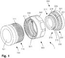
- the figure 1 shows an exploded view of a connecting device according to the invention.
- the connecting device 1 comprises a first media-carrying component 100, z. B. a distributor housing with several outlets, of which only the end portion 110 is shown here.
- the connecting device 1 further comprises a second media-carrying component 200 and a securing piece 300.
- the securing piece 300 is sleeve-like and includes an internal thread 311 which can be screwed onto the external thread 111 of the first media-carrying component 100 and which extends over half the axial extent of the securing piece 300 .
- the securing piece 300 has a receiving groove 321 behind the internal thread 311, behind which in turn is an inlet 330. This is described further below, in connection with FIG figure 2 , described in more detail.
- a hexagonal contour 340 is also formed on the outer casing of the securing piece 300 .
- the second media-carrying component 200 is shown, which is formed at the free end of the component body 201 .
- This component body 201 is adjoined by a connection section 210 for connection to the first media-carrying component 100 and the securing piece 300 .
- a fuse section 220 is formed in the connection section 210, adjacent to the component body 201 (see below, figure 2 ).
- a snap ring 225 made of spring steel is accommodated in this (cf. figure 3 ).
- a sealing section 211 is formed on the connection section 210 distally in front of the receiving groove 221 .
- This has a cylindrical outer shell 212 in which a circumferential receiving groove 214 is recessed.
- a greased O-ring 215 is added as a sealing element.
- the cylindrical outer shell 212 is dimensioned to fit in the bore 101 of the end section 110 of the first media-carrying component 100, so that the O-ring 215 seals against the shell surface of the bore 101 when it is received.
- the Figure 2a shows a longitudinal section through the connecting device 1 at the beginning of the insertion of the second media-carrying component (below) and in the connected state (above).
- the Figure 2b shows the detail section marked with a circle from the Figure 2a .
- the securing piece 300 is screwed with its internal thread 311 onto the external thread 111 in the end section 110 of the first media-carrying component 100 .
- the securing piece 300 contacts the front end of the end section 110 with an inner shoulder 312.
- the first media-carrying component 100 with the securing piece 300 screwed on is thus prepared for the production of a plug-in connection.
- the second media-carrying component 200 with snap ring 225 inserted in its receiving groove 221 is now inserted with its connection section 210 into the bore 101 of the first media-carrying component 100 .
- the outer shell 212 of the front seal portion 211 comes into contact with the inner shell of the cylindrical bore 101 and slides forward fittingly. Because the O-ring 215 is greased, it can be moved axially and rotated together with the second media-carrying component 200 without the risk of damage.
- the snap ring 225 is gripped by the inner surface of the inlet 330 of the locking piece and initially pre-centered by a slightly inclined first section 331 with respect to the longitudinal axis of the media-carrying components 100, 200. The gripping is supported by the positioning in the receiving groove 221 due to the ends bent inwards (see below, cf. figure 3 ). It follows the below in the Figure 2a situation shown.
- the snap ring 225 is compressed by a more steeply inclined second section 332 of the inlet 330, ie the two free ends (cf. figure 3 ) move towards each other, whereby the diameter of the snap ring 225 decreases.
- the O-ring 215 accommodated in the circumferential groove 214 of the second media-carrying component 200 comes into contact with the inner surface of the cylindrical bore 101 and seals the media-carrying components 100, 200 against one another in relation to the medium to be carried.
- the snap ring 225 has passed the end of the inlet 330, it gets into the receiving groove 321 of the locking piece 300.
- the second media-carrying component 200 is in contact with a correspondingly beveled section of the end section 110 of the first media-carrying component 100 via a bevel 216 of the connection section 210 distally located in front of the receiving groove and with a correspondingly shaped area of the connection section 210 on the inlet 330 of the securing piece 300.
- connection is secured axially by the snap ring 225 and sealed by the O-ring 215.
- the figure 3 shows a cross section through the connecting device in the connected state, in a plane AA (cf. Figure 2a ) perpendicular to the longitudinal axis of the media-carrying components.
- the snap ring 225 is accommodated in a peripheral receptacle with a symmetrically oval cross section, which is formed by the receptacle grooves 221, 321 in the second media-carrying component 200 or in the securing piece 300 (cf. Figure 2a ).
- the snap ring is circular and has a circular cross-section. Its ends 226a, 226b are bent inwards towards the center of symmetry.
- the snap ring 225 rests against the bottom of the receiving groove 321 of the securing piece 300 in the connected state of the connecting device, except in the region of its ends 226a, 226b. Because of this and because of the dimensioning of the receiving grooves 221, 321, it is ensured that the second media-carrying component 200 is fixed axially securely on the securing piece 300 (cf. also Figure 2b ).
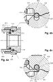
- the Figure 4a shows a longitudinal section through the second media-carrying component and the locking piece at the beginning of the release process (above) and after the snap ring has been compressed (below).
- the Figures 4b and 4c are details from the Figure 4a .
- the purpose of the release process is, after opening the connecting device by loosening the screw connection of the securing piece 300 to the first media-carrying component Securing piece 300 to remove from the second media-carrying component 200.
- a release tool 400 is used for this purpose.
- This has a hollow-cylindrical base body 401 in whose end area an external thread 411 is formed, which can interact with the internal thread 311 of the securing piece 300 .
- the release tool 400 On the front side, the release tool 400 has a peripheral axial web 405, which in turn has on the front side a front face 406 that tapers conically radially outwards towards the free end. Like in the Figure 4b is clearly visible, the web 405 and its end face 406 are positioned on the release tool 400 in such a way that when the same is screwed in, the end face 406 grips the snap ring 225 in the area of its radially outer half (cf. Figure 4b ), due to the (largely) rotationally symmetrical design of both the release tool 400 and the snap ring 225 along its entire circumference.
- the snap ring 225 is pressed radially inwards due to the conically widening end face 406 and is thus compressed. Finally, snap ring 225 is fully accommodated in receiving groove 221 of second media-carrying component 200 and no longer overlaps with securing piece 300 in the axial direction (cf. Figure 4c ). The second media-carrying component 200 can now easily be pulled axially out of the securing piece 300 . The snap ring 225 remains on the second media-carrying component 200. This is thus immediately ready for another plug-in connection.
- the invention is not limited to the illustrated embodiment.
- the shape of the various elements can be selected differently.
- a different type of elastic element can also be used.
- the seal between the media-carrying components can also be solved differently.
- the invention provides a connecting device which can be manufactured easily and safely and can be released again without being destroyed.
Landscapes
- Engineering & Computer Science (AREA)
- General Engineering & Computer Science (AREA)
- Mechanical Engineering (AREA)
- Quick-Acting Or Multi-Walled Pipe Joints (AREA)
Priority Applications (1)
| Application Number | Priority Date | Filing Date | Title |
|---|---|---|---|
| EP20209557.6A EP4001724B1 (fr) | 2020-11-24 | 2020-11-24 | Dispositif de raccordement pour composants guidant des milieux |
Applications Claiming Priority (1)
| Application Number | Priority Date | Filing Date | Title |
|---|---|---|---|
| EP20209557.6A EP4001724B1 (fr) | 2020-11-24 | 2020-11-24 | Dispositif de raccordement pour composants guidant des milieux |
Publications (2)
| Publication Number | Publication Date |
|---|---|
| EP4001724A1 true EP4001724A1 (fr) | 2022-05-25 |
| EP4001724B1 EP4001724B1 (fr) | 2024-05-29 |
Family
ID=73597803
Family Applications (1)
| Application Number | Title | Priority Date | Filing Date |
|---|---|---|---|
| EP20209557.6A Active EP4001724B1 (fr) | 2020-11-24 | 2020-11-24 | Dispositif de raccordement pour composants guidant des milieux |
Country Status (1)
| Country | Link |
|---|---|
| EP (1) | EP4001724B1 (fr) |
Citations (6)
| Publication number | Priority date | Publication date | Assignee | Title |
|---|---|---|---|---|
| FR2299588A1 (fr) * | 1975-01-30 | 1976-08-27 | Tch Hycop Ab | Accouplement de tube |
| US4105226A (en) * | 1976-06-01 | 1978-08-08 | Celanese Corporation | Snap-in fittings and coupling ring therefor |
| US20040090066A1 (en) * | 2002-04-15 | 2004-05-13 | Martin Hoffmann | Plug-in coupling for fluidic systems |
| US20080012326A1 (en) * | 2005-08-31 | 2008-01-17 | Oso Hotwater As | Connection valve |
| EP2014964B1 (fr) | 2007-06-05 | 2011-11-23 | R. Nussbaum AG | Armature |
| US8746750B2 (en) * | 2011-02-08 | 2014-06-10 | The Gates Corporation | Variable curvature clip for quick connect coupling |
-
2020
- 2020-11-24 EP EP20209557.6A patent/EP4001724B1/fr active Active
Patent Citations (6)
| Publication number | Priority date | Publication date | Assignee | Title |
|---|---|---|---|---|
| FR2299588A1 (fr) * | 1975-01-30 | 1976-08-27 | Tch Hycop Ab | Accouplement de tube |
| US4105226A (en) * | 1976-06-01 | 1978-08-08 | Celanese Corporation | Snap-in fittings and coupling ring therefor |
| US20040090066A1 (en) * | 2002-04-15 | 2004-05-13 | Martin Hoffmann | Plug-in coupling for fluidic systems |
| US20080012326A1 (en) * | 2005-08-31 | 2008-01-17 | Oso Hotwater As | Connection valve |
| EP2014964B1 (fr) | 2007-06-05 | 2011-11-23 | R. Nussbaum AG | Armature |
| US8746750B2 (en) * | 2011-02-08 | 2014-06-10 | The Gates Corporation | Variable curvature clip for quick connect coupling |
Also Published As
| Publication number | Publication date |
|---|---|
| EP4001724B1 (fr) | 2024-05-29 |
Similar Documents
| Publication | Publication Date | Title |
|---|---|---|
| DE69212793T2 (de) | Verbindungsvorrichtung für Teile eines Fluid-Verteilungssystems, besagte Teile und System | |
| DE69418701T2 (de) | Auf die aussenoberfläche eines polymer-rohres angreifende kupplung | |
| DE4335593C2 (de) | Einsteckteil für eine hydraulische Unterwasserkupplung | |
| DE69011769T2 (de) | Schnellkupplung. | |
| DE2625460C2 (fr) | ||
| CH253553A (de) | Rohrkupplung. | |
| DE20319959U1 (de) | Steckverbinder für Medienleitungen | |
| DE102011018465A1 (de) | Anziehwerkzeug für ein Schraubenelement mit einer Werkzeugaufnahme und einer zugeordneten Leitung sowie Kopplungsteil und Schraubenelement | |
| EP1070215B1 (fr) | Dispositif pour raccorder une tubulure, une piece de robinetterie ou un raccord tubulaire a un tuyau | |
| DE2921568A1 (de) | Steckverbindungs-anschlusstueck fuer druckluftbremsanlagen | |
| EP0126101A1 (fr) | Raccord de catheter | |
| DE19752528C2 (de) | Anschlußsteckvorrichtung für Kunststoffrohre | |
| DE60020212T2 (de) | Rohrverbindungselement, insbesondere für kunststoffrohre | |
| DE3923579A1 (de) | Anschlussarmatur fuer rohre, insbesondere fuer kunststoffrohre | |
| DE2528757C3 (de) | Anschlußverbindungseinheit | |
| EP0538196B1 (fr) | Dispositif pour le raccordement d'un tuyau flexible sous le crépi d'un mur et d'une robinetterie sur le crépi d'un mur | |
| EP4001724B1 (fr) | Dispositif de raccordement pour composants guidant des milieux | |
| DE102012201699A1 (de) | Anschlusseinrichtung für eine Sanitärarmatur | |
| DE3235125C2 (fr) | ||
| DE60305641T2 (de) | Verbindungsvorrichtung zur ende-zu-ende-verbindung von zwei rohren | |
| DE1675178A1 (de) | Rohrkupplung | |
| DE102019128040B4 (de) | Steckverbinder | |
| DE1110963B (de) | Rohrverbindung | |
| EP1475562A1 (fr) | Raccord de tuyaux | |
| DE3325350A1 (de) | Steckverbindung |
Legal Events
| Date | Code | Title | Description |
|---|---|---|---|
| PUAI | Public reference made under article 153(3) epc to a published international application that has entered the european phase |
Free format text: ORIGINAL CODE: 0009012 |
|
| STAA | Information on the status of an ep patent application or granted ep patent |
Free format text: STATUS: THE APPLICATION HAS BEEN PUBLISHED |
|
| AK | Designated contracting states |
Kind code of ref document: A1 Designated state(s): AL AT BE BG CH CY CZ DE DK EE ES FI FR GB GR HR HU IE IS IT LI LT LU LV MC MK MT NL NO PL PT RO RS SE SI SK SM TR |
|
| RIN1 | Information on inventor provided before grant (corrected) |
Inventor name: HUEBSCHER, MICHEL Inventor name: MEINL, MARKUS |
|
| STAA | Information on the status of an ep patent application or granted ep patent |
Free format text: STATUS: REQUEST FOR EXAMINATION WAS MADE |
|
| 17P | Request for examination filed |
Effective date: 20220923 |
|
| RBV | Designated contracting states (corrected) |
Designated state(s): AL AT BE BG CH CY CZ DE DK EE ES FI FR GB GR HR HU IE IS IT LI LT LU LV MC MK MT NL NO PL PT RO RS SE SI SK SM TR |
|
| GRAP | Despatch of communication of intention to grant a patent |
Free format text: ORIGINAL CODE: EPIDOSNIGR1 |
|
| STAA | Information on the status of an ep patent application or granted ep patent |
Free format text: STATUS: GRANT OF PATENT IS INTENDED |
|
| INTG | Intention to grant announced |
Effective date: 20240103 |
|
| GRAS | Grant fee paid |
Free format text: ORIGINAL CODE: EPIDOSNIGR3 |
|
| GRAA | (expected) grant |
Free format text: ORIGINAL CODE: 0009210 |
|
| STAA | Information on the status of an ep patent application or granted ep patent |
Free format text: STATUS: THE PATENT HAS BEEN GRANTED |
|
| AK | Designated contracting states |
Kind code of ref document: B1 Designated state(s): AL AT BE BG CH CY CZ DE DK EE ES FI FR GB GR HR HU IE IS IT LI LT LU LV MC MK MT NL NO PL PT RO RS SE SI SK SM TR |
|
| REG | Reference to a national code |
Ref country code: CH Ref legal event code: EP |
|
| REG | Reference to a national code |
Ref country code: IE Ref legal event code: FG4D Free format text: LANGUAGE OF EP DOCUMENT: GERMAN |
|
| REG | Reference to a national code |
Ref country code: DE Ref legal event code: R096 Ref document number: 502020008129 Country of ref document: DE |
|
| REG | Reference to a national code |
Ref country code: LT Ref legal event code: MG9D |
|
| REG | Reference to a national code |
Ref country code: NL Ref legal event code: MP Effective date: 20240529 |
|
| PG25 | Lapsed in a contracting state [announced via postgrant information from national office to epo] |
Ref country code: IS Free format text: LAPSE BECAUSE OF FAILURE TO SUBMIT A TRANSLATION OF THE DESCRIPTION OR TO PAY THE FEE WITHIN THE PRESCRIBED TIME-LIMIT Effective date: 20240929 |
|
| PG25 | Lapsed in a contracting state [announced via postgrant information from national office to epo] |
Ref country code: BG Free format text: LAPSE BECAUSE OF FAILURE TO SUBMIT A TRANSLATION OF THE DESCRIPTION OR TO PAY THE FEE WITHIN THE PRESCRIBED TIME-LIMIT Effective date: 20240529 |
|
| PG25 | Lapsed in a contracting state [announced via postgrant information from national office to epo] |
Ref country code: FI Free format text: LAPSE BECAUSE OF FAILURE TO SUBMIT A TRANSLATION OF THE DESCRIPTION OR TO PAY THE FEE WITHIN THE PRESCRIBED TIME-LIMIT Effective date: 20240529 Ref country code: HR Free format text: LAPSE BECAUSE OF FAILURE TO SUBMIT A TRANSLATION OF THE DESCRIPTION OR TO PAY THE FEE WITHIN THE PRESCRIBED TIME-LIMIT Effective date: 20240529 |
|
| PG25 | Lapsed in a contracting state [announced via postgrant information from national office to epo] |
Ref country code: GR Free format text: LAPSE BECAUSE OF FAILURE TO SUBMIT A TRANSLATION OF THE DESCRIPTION OR TO PAY THE FEE WITHIN THE PRESCRIBED TIME-LIMIT Effective date: 20240830 |
|
| PG25 | Lapsed in a contracting state [announced via postgrant information from national office to epo] |
Ref country code: ES Free format text: LAPSE BECAUSE OF FAILURE TO SUBMIT A TRANSLATION OF THE DESCRIPTION OR TO PAY THE FEE WITHIN THE PRESCRIBED TIME-LIMIT Effective date: 20240529 |
|
| PG25 | Lapsed in a contracting state [announced via postgrant information from national office to epo] |
Ref country code: PL Free format text: LAPSE BECAUSE OF FAILURE TO SUBMIT A TRANSLATION OF THE DESCRIPTION OR TO PAY THE FEE WITHIN THE PRESCRIBED TIME-LIMIT Effective date: 20240529 |
|
| PG25 | Lapsed in a contracting state [announced via postgrant information from national office to epo] |
Ref country code: LV Free format text: LAPSE BECAUSE OF FAILURE TO SUBMIT A TRANSLATION OF THE DESCRIPTION OR TO PAY THE FEE WITHIN THE PRESCRIBED TIME-LIMIT Effective date: 20240529 |
|
| PG25 | Lapsed in a contracting state [announced via postgrant information from national office to epo] |
Ref country code: PL Free format text: LAPSE BECAUSE OF FAILURE TO SUBMIT A TRANSLATION OF THE DESCRIPTION OR TO PAY THE FEE WITHIN THE PRESCRIBED TIME-LIMIT Effective date: 20240529 Ref country code: NO Free format text: LAPSE BECAUSE OF FAILURE TO SUBMIT A TRANSLATION OF THE DESCRIPTION OR TO PAY THE FEE WITHIN THE PRESCRIBED TIME-LIMIT Effective date: 20240829 Ref country code: LV Free format text: LAPSE BECAUSE OF FAILURE TO SUBMIT A TRANSLATION OF THE DESCRIPTION OR TO PAY THE FEE WITHIN THE PRESCRIBED TIME-LIMIT Effective date: 20240529 Ref country code: IS Free format text: LAPSE BECAUSE OF FAILURE TO SUBMIT A TRANSLATION OF THE DESCRIPTION OR TO PAY THE FEE WITHIN THE PRESCRIBED TIME-LIMIT Effective date: 20240929 Ref country code: HR Free format text: LAPSE BECAUSE OF FAILURE TO SUBMIT A TRANSLATION OF THE DESCRIPTION OR TO PAY THE FEE WITHIN THE PRESCRIBED TIME-LIMIT Effective date: 20240529 Ref country code: GR Free format text: LAPSE BECAUSE OF FAILURE TO SUBMIT A TRANSLATION OF THE DESCRIPTION OR TO PAY THE FEE WITHIN THE PRESCRIBED TIME-LIMIT Effective date: 20240830 Ref country code: FI Free format text: LAPSE BECAUSE OF FAILURE TO SUBMIT A TRANSLATION OF THE DESCRIPTION OR TO PAY THE FEE WITHIN THE PRESCRIBED TIME-LIMIT Effective date: 20240529 Ref country code: ES Free format text: LAPSE BECAUSE OF FAILURE TO SUBMIT A TRANSLATION OF THE DESCRIPTION OR TO PAY THE FEE WITHIN THE PRESCRIBED TIME-LIMIT Effective date: 20240529 Ref country code: BG Free format text: LAPSE BECAUSE OF FAILURE TO SUBMIT A TRANSLATION OF THE DESCRIPTION OR TO PAY THE FEE WITHIN THE PRESCRIBED TIME-LIMIT Effective date: 20240529 Ref country code: RS Free format text: LAPSE BECAUSE OF FAILURE TO SUBMIT A TRANSLATION OF THE DESCRIPTION OR TO PAY THE FEE WITHIN THE PRESCRIBED TIME-LIMIT Effective date: 20240829 |
|
| PG25 | Lapsed in a contracting state [announced via postgrant information from national office to epo] |
Ref country code: NL Free format text: LAPSE BECAUSE OF FAILURE TO SUBMIT A TRANSLATION OF THE DESCRIPTION OR TO PAY THE FEE WITHIN THE PRESCRIBED TIME-LIMIT Effective date: 20240529 |
|
| PG25 | Lapsed in a contracting state [announced via postgrant information from national office to epo] |
Ref country code: NL Free format text: LAPSE BECAUSE OF FAILURE TO SUBMIT A TRANSLATION OF THE DESCRIPTION OR TO PAY THE FEE WITHIN THE PRESCRIBED TIME-LIMIT Effective date: 20240529 |
|
| PG25 | Lapsed in a contracting state [announced via postgrant information from national office to epo] |
Ref country code: DK Free format text: LAPSE BECAUSE OF FAILURE TO SUBMIT A TRANSLATION OF THE DESCRIPTION OR TO PAY THE FEE WITHIN THE PRESCRIBED TIME-LIMIT Effective date: 20240529 |
|
| PG25 | Lapsed in a contracting state [announced via postgrant information from national office to epo] |
Ref country code: EE Free format text: LAPSE BECAUSE OF FAILURE TO SUBMIT A TRANSLATION OF THE DESCRIPTION OR TO PAY THE FEE WITHIN THE PRESCRIBED TIME-LIMIT Effective date: 20240529 |
|
| PG25 | Lapsed in a contracting state [announced via postgrant information from national office to epo] |
Ref country code: CZ Free format text: LAPSE BECAUSE OF FAILURE TO SUBMIT A TRANSLATION OF THE DESCRIPTION OR TO PAY THE FEE WITHIN THE PRESCRIBED TIME-LIMIT Effective date: 20240529 |
|
| PG25 | Lapsed in a contracting state [announced via postgrant information from national office to epo] |
Ref country code: RO Free format text: LAPSE BECAUSE OF FAILURE TO SUBMIT A TRANSLATION OF THE DESCRIPTION OR TO PAY THE FEE WITHIN THE PRESCRIBED TIME-LIMIT Effective date: 20240529 Ref country code: SK Free format text: LAPSE BECAUSE OF FAILURE TO SUBMIT A TRANSLATION OF THE DESCRIPTION OR TO PAY THE FEE WITHIN THE PRESCRIBED TIME-LIMIT Effective date: 20240529 |
|
| PG25 | Lapsed in a contracting state [announced via postgrant information from national office to epo] |
Ref country code: SM Free format text: LAPSE BECAUSE OF FAILURE TO SUBMIT A TRANSLATION OF THE DESCRIPTION OR TO PAY THE FEE WITHIN THE PRESCRIBED TIME-LIMIT Effective date: 20240529 |
|
| PG25 | Lapsed in a contracting state [announced via postgrant information from national office to epo] |
Ref country code: SM Free format text: LAPSE BECAUSE OF FAILURE TO SUBMIT A TRANSLATION OF THE DESCRIPTION OR TO PAY THE FEE WITHIN THE PRESCRIBED TIME-LIMIT Effective date: 20240529 Ref country code: SK Free format text: LAPSE BECAUSE OF FAILURE TO SUBMIT A TRANSLATION OF THE DESCRIPTION OR TO PAY THE FEE WITHIN THE PRESCRIBED TIME-LIMIT Effective date: 20240529 Ref country code: RO Free format text: LAPSE BECAUSE OF FAILURE TO SUBMIT A TRANSLATION OF THE DESCRIPTION OR TO PAY THE FEE WITHIN THE PRESCRIBED TIME-LIMIT Effective date: 20240529 Ref country code: EE Free format text: LAPSE BECAUSE OF FAILURE TO SUBMIT A TRANSLATION OF THE DESCRIPTION OR TO PAY THE FEE WITHIN THE PRESCRIBED TIME-LIMIT Effective date: 20240529 Ref country code: DK Free format text: LAPSE BECAUSE OF FAILURE TO SUBMIT A TRANSLATION OF THE DESCRIPTION OR TO PAY THE FEE WITHIN THE PRESCRIBED TIME-LIMIT Effective date: 20240529 Ref country code: CZ Free format text: LAPSE BECAUSE OF FAILURE TO SUBMIT A TRANSLATION OF THE DESCRIPTION OR TO PAY THE FEE WITHIN THE PRESCRIBED TIME-LIMIT Effective date: 20240529 |
|
| PG25 | Lapsed in a contracting state [announced via postgrant information from national office to epo] |
Ref country code: IT Free format text: LAPSE BECAUSE OF FAILURE TO SUBMIT A TRANSLATION OF THE DESCRIPTION OR TO PAY THE FEE WITHIN THE PRESCRIBED TIME-LIMIT Effective date: 20240529 |
|
| REG | Reference to a national code |
Ref country code: DE Ref legal event code: R097 Ref document number: 502020008129 Country of ref document: DE |
|
| PLBE | No opposition filed within time limit |
Free format text: ORIGINAL CODE: 0009261 |
|
| STAA | Information on the status of an ep patent application or granted ep patent |
Free format text: STATUS: NO OPPOSITION FILED WITHIN TIME LIMIT |
|
| PG25 | Lapsed in a contracting state [announced via postgrant information from national office to epo] |
Ref country code: SI Free format text: LAPSE BECAUSE OF FAILURE TO SUBMIT A TRANSLATION OF THE DESCRIPTION OR TO PAY THE FEE WITHIN THE PRESCRIBED TIME-LIMIT Effective date: 20240529 |
|
| 26N | No opposition filed |
Effective date: 20250303 |
|
| PG25 | Lapsed in a contracting state [announced via postgrant information from national office to epo] |
Ref country code: MC Free format text: LAPSE BECAUSE OF FAILURE TO SUBMIT A TRANSLATION OF THE DESCRIPTION OR TO PAY THE FEE WITHIN THE PRESCRIBED TIME-LIMIT Effective date: 20240529 |
|
| PG25 | Lapsed in a contracting state [announced via postgrant information from national office to epo] |
Ref country code: LU Free format text: LAPSE BECAUSE OF NON-PAYMENT OF DUE FEES Effective date: 20241124 |
|
| GBPC | Gb: european patent ceased through non-payment of renewal fee |
Effective date: 20241124 |
|
| REG | Reference to a national code |
Ref country code: BE Ref legal event code: MM Effective date: 20241130 |
|
| PG25 | Lapsed in a contracting state [announced via postgrant information from national office to epo] |
Ref country code: SE Free format text: LAPSE BECAUSE OF FAILURE TO SUBMIT A TRANSLATION OF THE DESCRIPTION OR TO PAY THE FEE WITHIN THE PRESCRIBED TIME-LIMIT Effective date: 20240529 |
|
| PG25 | Lapsed in a contracting state [announced via postgrant information from national office to epo] |
Ref country code: BE Free format text: LAPSE BECAUSE OF NON-PAYMENT OF DUE FEES Effective date: 20241130 Ref country code: GB Free format text: LAPSE BECAUSE OF NON-PAYMENT OF DUE FEES Effective date: 20241124 |
|
| PG25 | Lapsed in a contracting state [announced via postgrant information from national office to epo] |
Ref country code: FR Free format text: LAPSE BECAUSE OF NON-PAYMENT OF DUE FEES Effective date: 20241130 |
|
| PG25 | Lapsed in a contracting state [announced via postgrant information from national office to epo] |
Ref country code: IE Free format text: LAPSE BECAUSE OF NON-PAYMENT OF DUE FEES Effective date: 20241124 |
|
| REG | Reference to a national code |
Ref country code: CH Ref legal event code: U11 Free format text: ST27 STATUS EVENT CODE: U-0-0-U10-U11 (AS PROVIDED BY THE NATIONAL OFFICE) Effective date: 20251201 |
|
| PGFP | Annual fee paid to national office [announced via postgrant information from national office to epo] |
Ref country code: DE Payment date: 20251119 Year of fee payment: 6 |
|
| PGFP | Annual fee paid to national office [announced via postgrant information from national office to epo] |
Ref country code: AT Payment date: 20260113 Year of fee payment: 5 |
|
| PGFP | Annual fee paid to national office [announced via postgrant information from national office to epo] |
Ref country code: CH Payment date: 20251201 Year of fee payment: 6 |
|
| PG25 | Lapsed in a contracting state [announced via postgrant information from national office to epo] |
Ref country code: PT Free format text: LAPSE BECAUSE OF NON-PAYMENT OF DUE FEES Effective date: 20240529 |
|
| PG25 | Lapsed in a contracting state [announced via postgrant information from national office to epo] |
Ref country code: HU Free format text: LAPSE BECAUSE OF FAILURE TO SUBMIT A TRANSLATION OF THE DESCRIPTION OR TO PAY THE FEE WITHIN THE PRESCRIBED TIME-LIMIT; INVALID AB INITIO Effective date: 20201124 |
|
| PG25 | Lapsed in a contracting state [announced via postgrant information from national office to epo] |
Ref country code: CY Free format text: LAPSE BECAUSE OF FAILURE TO SUBMIT A TRANSLATION OF THE DESCRIPTION OR TO PAY THE FEE WITHIN THE PRESCRIBED TIME-LIMIT; INVALID AB INITIO Effective date: 20201124 |