EP4001735A1 - Überwachung von rohrleitungssystemen - Google Patents
Überwachung von rohrleitungssystemen Download PDFInfo
- Publication number
- EP4001735A1 EP4001735A1 EP20208251.7A EP20208251A EP4001735A1 EP 4001735 A1 EP4001735 A1 EP 4001735A1 EP 20208251 A EP20208251 A EP 20208251A EP 4001735 A1 EP4001735 A1 EP 4001735A1
- Authority
- EP
- European Patent Office
- Prior art keywords
- marking
- markings
- recording
- components
- pair
- Prior art date
- Legal status (The legal status is an assumption and is not a legal conclusion. Google has not performed a legal analysis and makes no representation as to the accuracy of the status listed.)
- Granted
Links
Images


Classifications
-
- F—MECHANICAL ENGINEERING; LIGHTING; HEATING; WEAPONS; BLASTING
- F17—STORING OR DISTRIBUTING GASES OR LIQUIDS
- F17D—PIPE-LINE SYSTEMS; PIPE-LINES
- F17D5/00—Protection or supervision of installations
-
- G—PHYSICS
- G06—COMPUTING OR CALCULATING; COUNTING
- G06T—IMAGE DATA PROCESSING OR GENERATION, IN GENERAL
- G06T7/00—Image analysis
- G06T7/0002—Inspection of images, e.g. flaw detection
- G06T7/0004—Industrial image inspection
- G06T7/001—Industrial image inspection using an image reference approach
-
- F—MECHANICAL ENGINEERING; LIGHTING; HEATING; WEAPONS; BLASTING
- F17—STORING OR DISTRIBUTING GASES OR LIQUIDS
- F17D—PIPE-LINE SYSTEMS; PIPE-LINES
- F17D3/00—Arrangements for supervising or controlling working operations
-
- G—PHYSICS
- G01—MEASURING; TESTING
- G01M—TESTING STATIC OR DYNAMIC BALANCE OF MACHINES OR STRUCTURES; TESTING OF STRUCTURES OR APPARATUS, NOT OTHERWISE PROVIDED FOR
- G01M5/00—Investigating the elasticity of structures, e.g. deflection of bridges or air-craft wings
- G01M5/0041—Investigating the elasticity of structures, e.g. deflection of bridges or air-craft wings by determining deflection or stress
- G01M5/005—Investigating the elasticity of structures, e.g. deflection of bridges or air-craft wings by determining deflection or stress by means of external apparatus, e.g. test benches or portable test systems
- G01M5/0058—Investigating the elasticity of structures, e.g. deflection of bridges or air-craft wings by determining deflection or stress by means of external apparatus, e.g. test benches or portable test systems of elongated objects, e.g. pipes, masts, towers or railways
-
- G—PHYSICS
- G01—MEASURING; TESTING
- G01M—TESTING STATIC OR DYNAMIC BALANCE OF MACHINES OR STRUCTURES; TESTING OF STRUCTURES OR APPARATUS, NOT OTHERWISE PROVIDED FOR
- G01M5/00—Investigating the elasticity of structures, e.g. deflection of bridges or air-craft wings
- G01M5/0091—Investigating the elasticity of structures, e.g. deflection of bridges or air-craft wings by using electromagnetic excitation or detection
-
- G—PHYSICS
- G06—COMPUTING OR CALCULATING; COUNTING
- G06K—GRAPHICAL DATA READING; PRESENTATION OF DATA; RECORD CARRIERS; HANDLING RECORD CARRIERS
- G06K7/00—Methods or arrangements for sensing record carriers, e.g. for reading patterns
- G06K7/10—Methods or arrangements for sensing record carriers, e.g. for reading patterns by electromagnetic radiation, e.g. optical sensing; by corpuscular radiation
- G06K7/14—Methods or arrangements for sensing record carriers, e.g. for reading patterns by electromagnetic radiation, e.g. optical sensing; by corpuscular radiation using light without selection of wavelength, e.g. sensing reflected white light
- G06K7/1404—Methods for optical code recognition
- G06K7/1408—Methods for optical code recognition the method being specifically adapted for the type of code
- G06K7/1417—2D bar codes
-
- G—PHYSICS
- G06—COMPUTING OR CALCULATING; COUNTING
- G06K—GRAPHICAL DATA READING; PRESENTATION OF DATA; RECORD CARRIERS; HANDLING RECORD CARRIERS
- G06K7/00—Methods or arrangements for sensing record carriers, e.g. for reading patterns
- G06K7/10—Methods or arrangements for sensing record carriers, e.g. for reading patterns by electromagnetic radiation, e.g. optical sensing; by corpuscular radiation
- G06K7/14—Methods or arrangements for sensing record carriers, e.g. for reading patterns by electromagnetic radiation, e.g. optical sensing; by corpuscular radiation using light without selection of wavelength, e.g. sensing reflected white light
- G06K7/1404—Methods for optical code recognition
- G06K7/1439—Methods for optical code recognition including a method step for retrieval of the optical code
- G06K7/1443—Methods for optical code recognition including a method step for retrieval of the optical code locating of the code in an image
-
- G—PHYSICS
- G06—COMPUTING OR CALCULATING; COUNTING
- G06T—IMAGE DATA PROCESSING OR GENERATION, IN GENERAL
- G06T7/00—Image analysis
- G06T7/70—Determining position or orientation of objects or cameras
-
- F—MECHANICAL ENGINEERING; LIGHTING; HEATING; WEAPONS; BLASTING
- F16—ENGINEERING ELEMENTS AND UNITS; GENERAL MEASURES FOR PRODUCING AND MAINTAINING EFFECTIVE FUNCTIONING OF MACHINES OR INSTALLATIONS; THERMAL INSULATION IN GENERAL
- F16L—PIPES; JOINTS OR FITTINGS FOR PIPES; SUPPORTS FOR PIPES, CABLES OR PROTECTIVE TUBING; MEANS FOR THERMAL INSULATION IN GENERAL
- F16L2201/00—Special arrangements for pipe couplings
- F16L2201/10—Indicators for correct coupling
-
- F—MECHANICAL ENGINEERING; LIGHTING; HEATING; WEAPONS; BLASTING
- F16—ENGINEERING ELEMENTS AND UNITS; GENERAL MEASURES FOR PRODUCING AND MAINTAINING EFFECTIVE FUNCTIONING OF MACHINES OR INSTALLATIONS; THERMAL INSULATION IN GENERAL
- F16L—PIPES; JOINTS OR FITTINGS FOR PIPES; SUPPORTS FOR PIPES, CABLES OR PROTECTIVE TUBING; MEANS FOR THERMAL INSULATION IN GENERAL
- F16L2201/00—Special arrangements for pipe couplings
- F16L2201/60—Identification or marking
-
- G—PHYSICS
- G06—COMPUTING OR CALCULATING; COUNTING
- G06T—IMAGE DATA PROCESSING OR GENERATION, IN GENERAL
- G06T2207/00—Indexing scheme for image analysis or image enhancement
- G06T2207/30—Subject of image; Context of image processing
- G06T2207/30108—Industrial image inspection
-
- G—PHYSICS
- G06—COMPUTING OR CALCULATING; COUNTING
- G06T—IMAGE DATA PROCESSING OR GENERATION, IN GENERAL
- G06T2207/00—Indexing scheme for image analysis or image enhancement
- G06T2207/30—Subject of image; Context of image processing
- G06T2207/30204—Marker
Definitions
- Pipeline systems are known from the prior art that have markings that allow the pipes and their position to be identified. By recognizing the marking, it is possible to evaluate what type of pipe has been used. For example, the marking can be arranged on the inner circumference of the pipe, which is recognized by a sewer robot and the corresponding data, which were already recorded and stored when the line was laid, are displayed. This also allows the position of pipeline components that are installed underground to be determined by assigning the coordinates to the routed components during installation.
- this object is achieved in that at least two markings are arranged in such a way that they are recorded together on a base recording. At least two markings are arranged on the pipeline system in the system according to the invention, with two markings each forming a pair, with the pair of markings being recorded in a base receptacle.
- the method according to the invention for detecting displacements in installed pipeline systems and identifying components and their properties includes arranging or attaching a marking to at least one of the components of the installed pipeline system. Each mark is unique, distinctive and unique. The arrangement or attachment of the marking can be done by sticking, embossing or in some other known way. The marking is preferably only applied when the pipe system has been completely installed or at least this area of the pipe system is firmly anchored. The marking attached to the piping system is recorded or scanned or photographed and a basic recording of the initial state is generated or created. Whether recording, scanning or photography is used depends on which tool is used to do this. A mobile device or a digital camera is preferably used for this purpose, and these can preferably be connected to a computer.
- the marking is preferably recorded or scanned or photographed in such a way that at least a partial area of the components of the pipeline system can be seen on the base recording. It is an advantage if a 3D scan is carried out, this enables a good 3-dimensional measurement of the installation, especially in the Z-direction.
- Properties and data are assigned and stored to the detected marking, with the properties and data preferably being based on the obtain the corresponding component on which the marking is applied. For example, the location of the marking can also be stored, as well as information on the installer of the pipe system or the time of installation, etc..
- the baseline recording is stored, preferably in a database, it being advantageous if the stored baseline recordings or the stored data can be accessed from anywhere, or the database, which would make a cloud solution possible.
- the basic recording of the initial state is also assigned and stored to the corresponding marking or marking pair.
- a follow-up recording is preferably created by re-detecting or scanning or photographing the marking.
- the marking which is unique, is recognized autonomously and the follow-up image is compared with the base image. By comparing, changes or shifts in the marking in relation to the baseline recording are determined. The determined values are then output accordingly.
- the follow-up recording and further follow-up recordings are also saved, this allows a history to be created which shows the change or shift in the pipe system at a point over a specific period of time.
- the present method according to the invention includes that at least two markings are arranged on a pipeline system in such a way that they are recorded together on a base recording.
- the method according to the invention makes it possible to detect a displacement of the markings in the horizontal and vertical direction as well as in depth, or in the X, Y and Z direction. An angular displacement ⁇ can also be detected and evaluated using the method according to the invention.
- QR code is used for marking. Due to the uniqueness of such a QR code, it is clearly recognized. In addition, the shifting is easy due to the geometric design of the code determine and the definition of the shift or change in the X, Y, and Z direction or horizontally, vertically or in depth, as well as angular shifts can be determined and defined.
- a preferred embodiment consists in that at least two markings are arranged on different components or on one component and one structural element. This makes it easy to see a shift in the components relative to one another.
- a structural element is a wall, floor, ceiling or pillar or other stable structure to which a pipe system is usually attached.
- Two markers are preferably arranged, with the two markers forming a pair which is detected on the base receptacle.
- one marking forms the "master” and the other marking forms the "slave", which means that the displacement of the markings in the respective X, Y and Z directions can be determined easily.
- Each subsequent shot is saved accordingly, so that a successive shift can be seen.
- the constant monitoring by means of the recorded follow-up recordings can be used, for example, to set an automatic alarm that is triggered, for example, when a certain displacement value is reached or exceeded. How this alarm occurs is a matter of personal choice, whether it be a notification to piping system maintenance or a warning light or other known alarm system.
- An assessment of the displacement and/or a recommendation for suppressing a displacement of the pipeline system at the corresponding point is preferably calculated using the determined values of the displacement or change in the position of the marking that occurs.
- An algorithm is preferably used for the calculation.
- the determined values use an algorithm to calculate an assessment of the shift and/or a recommendation for reducing the shift. This can prevent the pipe system from leaking or cracks from forming or screw connections from loosening such as other unwanted problems with the piping system can also be avoided.
- a further refinement of the method is that the algorithm is continuously optimized and is therefore self-learning.
- the inventive system for detecting shifts in installed piping systems and identifying components and their properties includes an installed piping system and its components, such as pipes, valves, fittings, couplings, etc., and fasteners and components to which the fasteners are fixed.
- the system includes markings, with at least two markings being arranged on the piping system and preferably applied after the piping system has been installed. Two markers each form a pair, with the pair of markers being recorded in a base recording.
- the basic recording documents the initial state, directly after the installation of the pipeline.
- the piping system is a system that is not buried in the ground but is anchored to structural elements such as walls, ceilings, floors or other fixed elements by means of fastening elements and is more or less accessible, especially insofar as photographs are taken of the markings can become.
- the marking is formed by a QR code. This has the advantage that each marking is unique and therefore cannot be confused.
- the desired data and properties are then stored in the marking or QR code, as already described above.
- one marking of the pair of markings is arranged on one component of the pipeline system and the other marking on another component or a structural element or a fastening element. Since there are usually shifts and changes between the individual components in the pipeline system, it is advantageous if the markings of the marking pair, which are in the form of a QR code, are not arranged on the same component.
- the system includes a mobile terminal and/or a digital camera for capturing/scanning/photographing the marking.
- the system has a memory that makes it possible to store the recorded recordings such as basic recordings and follow-up recordings. Furthermore, it is advantageous if the system has a computing unit that allows the recordings to be evaluated accordingly by means of an algorithm, as described above.
- the mobile terminal device also enables the determined values to be output, as well as the assessment of these and, if available, also a recommendation for reducing the displacement of the pipeline.
- markings 3 are arranged on components 2 of the pipe system 1 or also on structural elements 13 such as walls, pillars, etc., with the markings obviously being able to be arranged on any possible component of the pipe system 1.
- markings 3 to 5 further options for arranging markings 3, which are preferably in the form of a QR code, on components 2 of the pipeline system 1 are disclosed, this listing of course not being conclusive.
- the marking 3, which is preferably in the form of a QR code is recorded or scanned or photographed, preferably with a mobile device 7 or a digital camera 7.
- a base recording 4 which shows the initial state of the pipeline 1 at this position or with the recorded components 2 and/or structural elements 13, this can be found in Section B.
- the exact position and alignment of the two markings 3 relative to one another is recorded by the base receptacle 4 .
- the markers 3 properties and data are assigned and stored. For example, properties of the respective component, properties of the pipeline, location, etc..
- the base recording 4 is preferably stored in a database 5 or another storage location, it being advantageous if there is the possibility of remote access and various users can access it, whereby a Saving in a cloud is also conceivable.
- the marking is recorded again or scanned or photographed, as shown in Section C.
- the two markings 3, ie the same pair of markings 8, are recorded again, preferably again with a mobile terminal device or a digital camera that can be connected to a computer.
- a computing unit is used to autonomously identify which marking 3 or pair of markings 8 is involved and at the same time a comparison of the positions of the markings with one another is carried out, which can be seen in section D. It is also advantageous if the renewed detection of the pair of markings 8 is also stored as a follow-up picture 6, and further follow-up pictures 6 can also be created and saved, so that a shift or change in the pipeline system 1 can be observed in the corresponding components 2.
- the determined values ⁇ X, ⁇ Y, ⁇ Z, ⁇ of the displacement are then output 11; this can also be displayed on a mobile terminal 7 or by another display device, which is shown in Section E.
- a visual output of the values can also be dispensed with and the values are processed immediately or used for further calculations or simply stored for the time being.
- the method according to the invention can also be used to monitor a pipeline system 1 in that regular follow-up recordings 6 are recorded and the shift is automatically determined, based on which an alarm is also issued can be stored, which is triggered when a value of the shift is exceeded or reached. Maximum values should be defined and stored for this purpose.
- the method is stored with an algorithm which, based on the determined values of the shift between the basic recording and the subsequent recording of the marking pair 8, makes it possible to provide an assessment of the shift and/or a recommendation as to how the shift can be reduced, or what For example, to improve the attachment 12 of the pipe system or other recommendations.
- In 2 shows how the values ⁇ X, ⁇ Y, ⁇ Z, ⁇ are preferably determined.
- one of the two markings is defined as master 9 and the other of the marking pair 8 as slave 10.
- This allows the displacement of the markings 3 relative to each other to be well defined in the directions X, Y and Z as well as in an angular displacement ⁇ and calculate, where only the X, Y directions and the angular displacement ⁇ are shown here, the Z direction is the depth here and can of course be determined in the same way. It is also not necessary to determine all values, sometimes two are sufficient.
- angular displacements ⁇ can also be detected.
- FIG. 3 shows a flange coupling as a possible component 2 of the pipeline 1 on the flanges of which a marking 3 is arranged and which form a pair of markings 8 .
- 4 shows a pipeline 1 attached to a structural element 13, in which the markings 3 are on an elbow and a pipe were attached.
- the markings 3 are applied after the pipe system 1 has been laid, and the installer usually decides on which components 2 or structural elements 13. As a rule, those components 2 and structural elements 13 are selected in which a displacement or change in the pipeline 1 is easily recognizable and they are also most likely to tend to do so due to their position or their installation and represent a danger point for leaks.
- Fastening elements 12 which fasten a pipeline 1 to a component 13 are usual.
- markings 3 or pairs of markings 8 can also be arranged next to one another on a pipe, as in figure 5 shown.
- This can be used to detect expansion or contraction as in the first image, or inflation of the pipe as in the second image figure 5 6 shows the system according to the invention for detecting a shift or change in an installed pipeline system 1.
- the system includes an installed pipeline system 1 with components 2, fastening elements 12 and markings 3.
- the basic recording is an image of the initial state and is saved accordingly and stored as a comparison value.
- 6 it can be seen that a change in component 2 has occurred.
- the first image represents the basic image 4 and the second shows the displacement through the values ⁇ X and ⁇ Y, which are then preferably recorded in a subsequent image 6 for comparison.
Landscapes
- Engineering & Computer Science (AREA)
- Physics & Mathematics (AREA)
- General Physics & Mathematics (AREA)
- Computer Vision & Pattern Recognition (AREA)
- Theoretical Computer Science (AREA)
- Electromagnetism (AREA)
- Toxicology (AREA)
- Artificial Intelligence (AREA)
- General Health & Medical Sciences (AREA)
- Health & Medical Sciences (AREA)
- Mechanical Engineering (AREA)
- General Engineering & Computer Science (AREA)
- Aviation & Aerospace Engineering (AREA)
- Quality & Reliability (AREA)
- Length Measuring Devices By Optical Means (AREA)
- Image Processing (AREA)
- Pipeline Systems (AREA)
- Examining Or Testing Airtightness (AREA)
Abstract
• anordnen / anbringen einer Markierung auf mindestens einer der Komponenten des installierten Rohrleitungssystems,
• erfassen / scannen / fotografieren der Markierung (3) und generieren einer Basisaufnahme des Ausgangszustands,
• der Markierung Eigenschaften und Daten zuweisen und hinterlegen,
• speichern der Basisaufnahme an einem Speicherort,
• erneutes erfassen / scannen / fotografieren der Markierung,
• autonomes erkennen der Markierung und vergleichen mit der gespeicherten Basisaufnahme der entsprechenden Markierung,
• ermitteln von Veränderungen oder Verschiebungen der Markierung,
• Ausgabe von ermittelten Werten,
wobei mindestens zwei Markierungen so angeordnet sind, dass sie auf einer Basisaufnahme gemeinsam erfasst werden.
Description
- Die Erfindung betrifft ein Verfahren und ein System zur Erkennung von Verschiebungen in installierten Rohrleitungssystemen und Identifizierung von Komponenten und deren Eigenschaften, beinhaltend:
- anordnen / anbringen einer Markierung auf mindestens einer der Komponenten des installierten Rohrleitungssystems,
- erfassen / scannen / fotografieren der Markierung und generieren einer Basisaufnahme des Ausgangszustands,
- speichern der Basisaufnahme vorzugsweise in einer Datenbank,
- der Basisaufnahme entsprechende Eigenschaften und Daten zuweisen und hinterlegen,
- erneutes erfassen / scannen / fotografieren der Markierung,
- autonomes erkennen der Markierung und vergleichen mit der gespeicherten Basisaufnahme der entsprechenden Markierung,
- ermitteln von Veränderungen oder Verschiebungen der Markierung,
- Ausgabe von ermittelten Werten.
- Aus dem Stand der Technik sind Rohrleitungssysteme bekannt die Markierungen aufweisen, die es erlauben die Rohre und ihre Position zu identifizieren. Durch die Erkennung der Markierung kann evaluiert werden, welche Art von Rohr eingesetzt wurde. Beispielsweise kann die Markierung am Innenumfang des Rohres angeordnet sein, die mittels eines Kanalroboters erkannt wird und die entsprechenden Daten, welche bereits beim Verlegen der Leitung erfasst und gespeichert wurden werden angezeigt. Dies lässt auch eine Ermittlung der Position von Rohrleitungskomponenten zu, die unter der Erde verbaut sind, indem der verlegten Komponente bereits die Koordinaten bei der Installation zugewiesen werden.
- Die
US 2001/0029989 A1 offenbart eine alphanummerische Markierung für Rohrleitungen, welche es erlaubt die Position sowie die Rohrleitung zu identifizieren. - Die aus dem Stand der Technik bekannten Systeme lassen eine Identifizierung der Rohrleitung sowie die Erkennung deren Position zu, jedoch ermöglichen sie keine Erkennung von Veränderungen im Rohrleitungssystem.
- Es ist Aufgabe der Erfindung ein Verfahren und ein damit verbundenes System vorzuschlagen, dass es erlaubt auftretende Spannungen in bereits verlegten und installierten Rohrleitungssystemen frühzeitig zu erkennen um eventuell entstehende Leckagen oder Rohrbrüche zu verhindern.
- Diese Aufgabe wird erfindungsgemäss dadurch gelöst, dass mindestens zwei Markierungen so angeordnet sind, dass sie auf einer Basisaufnahme gemeinsam erfasst werden. Wobei am erfindungsgemässen System mindestens zwei Markierungen am Rohrleitungssystem angeordnet sind, wobei jeweils zwei Markierungen ein Paar bilden, wobei das Markierungspaar in einer Basisaufnahme erfasst ist.
- Das erfindungsgemässe Verfahren zur Erkennung von Verschiebungen in installierten Rohrleitungssystemen und Identifizierung von Komponenten und deren Eigenschaften, beinhaltet ein Anordnen bzw. Anbringen einer Markierung auf mindestens einer der Komponenten des installierten Rohrleitungssystems. Jede Markierung ist eindeutig, unverwechselbar und einzigartig. Das Anordnen bzw. Anbringen der Markierung kann durch aufkleben, einprägen oder auf andere bekannte Weise erfolgen. Vorzugsweise wird die Markierung erst angebracht, wenn das Rohrleitungssystem fertig installiert ist oder zumindest dieser Bereich des Rohrleitungssystems fest verankert ist.
Die am Rohrleitungssystem angebrachte Markierung wird erfasst bzw. gescannt bzw. fotografiert und es wird eine Basisaufnahme des Ausgangszustands generiert oder erstellt. Ob ein Erfassen, Scannen oder Photographien angewandt wird ist abhängig davon mit welchem Tool dies durchgeführt wird, vorzugsweise wird dazu ein mobiles Endgerät oder eine Digitalkamera verwendet, wobei diese vorzugsweise mit einem Rechner verbindbar sind. Vorzugsweise wird die Markierung so erfasst bzw. gescannt bzw. fotografiert, dass auf der Basisaufnahme zumindest ein Teilbereich der Komponenten des Rohrleitungssystems ersichtlich ist. Es ist von Vorteil, wenn ein 3D Scann durchgeführt wird, dies ermöglicht eine gute 3-dimensionale Vermessungen der Installation speziell in Z-Richtung.
Der erfassten Markierung werden Eigenschaften und Daten zugewiesen und hinterlegt, wobei die Eigenschaften und Daten sich vorzugsweise auf die entsprechende Komponente beziehen, auf der die Markierung angebracht ist. Beispielsweise kann auch der Standort der Markierung hinterlegt werden, wie auch Angaben zum Installateur des Rohrleitungssystems oder der Verbauungszeitpunkt, etc..
Die Basisaufnahme wird gespeichert, vorzugsweise in einer Datenbank, wobei es vorteilhaft ist, wenn von überall auf die gespeicherten Basisaufnahmen bzw. auf die hinterlegten Daten zugegriffen werden kann oder auf die Datenbank, wodurch sich eine Cloud-Lösung anbieten würde. Es ist vorteilhaft wenn die Basisaufnahme des Ausgangszustands ebenfalls der entsprechenden Markierung bzw. dem Markierungspaar zugewiesen und hinterlegt wird.
Durch ein erneutes Erfassen oder Scannen oder Fotografieren der Markierung, wird vorzugsweise eine Folgeaufnahme erstellt. Des Weiteren wird autonom die Markierung, welche einzigartig ist erkannt und die Folgeaufnahme mit der Basisaufnahme verglichen. Durch das Vergleichen werden Veränderungen oder Verschiebungen der Markierung in Bezug auf die Basisaufnahme ermittelt. Die ermittelten Werte werden dann entsprechend ausgegeben. Es ist vorteilhaft wenn die Folgeaufnahme und weitere Folgeaufnahmen ebenfalls gespeichert werden, dadurch lässt sich eine Historie erstellen, welche die Veränderung bzw. Verschiebung des Rohrleitungssystems an einer Stelle über eine bestimmte Zeit aufzeigt.
Das vorliegende erfindungsgemässe Verfahren beinhaltet, dass an einem Rohrleitungssystem mindestens zwei Markierungen so angeordnet werden, dass sie auf einer Basisaufnahme gemeinsam erfasst werden. Dies erlaubt, das Erkennen der Verschiebung der beiden Markierungen zueinander. Dadurch kann festgestellt werden, wie sich eine Markierung bzw. in welche Richtungen und wie weit sie sich im Vergleich zur anderen verschoben hat. Daraus kann ermittelt werden wie sich das Rohrleitungssystem und seine Komponenten in seiner Lage verändert bzw. verschoben haben. Das erfindungsgemässe Verfahren ermöglicht die Erkennung einer Verschiebung der Markierungen in horizontaler und vertikaler Richtung sowie auch in der Tiefe, bzw. in X-, Y- und Z-Richtung. Auch eine Winkelverschiebung θ kann mit dem erfindungsgemässen Verfahren erfasst und ausgewertet werden. - Es ist vorteilhaft, wenn zur Markierung ein QR-Code verwendet wird. Durch die Einzigartigkeit eines solchen QR-Codes wird er eindeutig wiedererkannt. Zudem ist durch die geometrische Ausgestaltung des Codes die Verschiebung einfach zu ermitteln sowie die Definition der Verschiebung oder Veränderung in die X-, Y, und Z-Richtung bzw. horizontal, vertikal oder in die Tiefe, wie auch Winkelverschiebungen ermittelt und definiert werden können.
- Eine bevorzugte Ausführungsform besteht darin, dass mindestens zwei Markierungen an unterschiedlichen Komponenten oder an einer Komponente und einem Bauelement angeordnet werden. Dadurch lässt sich einer Verschiebung der Komponenten zueinander gut erkennen. Als Bauelement ist eine Wand, ein Boden, eine Decke oder Pfeiler oder sonstige stabile Strukturen an denen ein Rohrleitungssystem in der Regel befestigt wird.
- Vorzugsweise werden zwei Markierungen angeordnet, wobei die beiden Markierungen ein Paar bilden, welches auf der Basisaufnahme erfasst wird. Dadurch bildet die eine Markierung den "Master" und die andere Markierung den "Slave" wodurch sich die Verschiebung der Markierungen gut in die jeweilige Richtung X, Y und Z ermitteln lässt. Jede Folgeaufnahme wird entsprechend gespeichert wodurch eine sukzessive Verschiebung erkennbar ist.
- Vorzugsweise kann durch die stetige Überwachung mittels den erfassten Folgeaufnahmen beispielsweise ein automatischer Alarm gesetzt werden der beispielsweise auslöst, wenn ein bestimmter Wert der Verschiebung erreicht oder überschritten ist. Wie dieser Alarm erfolgt ist individuell zu handhaben, sei es mittels einer Mitteilung an den Rohrleitungssystemunterhalt oder einer Warnleuchte oder sonst einem bekannten Alarmsystem.
- Vorzugsweise wird mittels den ermittelten Werten der auftretenden Verschiebung bzw. Veränderung der Position der Markierung eine Beurteilung der Verschiebung und/oder eine Empfehlung zur Unterdrückung einer Verschiebung des Rohrleitungssystems an der entsprechenden Stelle kalkuliert. Vorzugsweise wird zur Kalkulation ein Algorithmus verwendet.
- Es ist vorteilhaft, wenn die ermittelten Werte mittels eins Algorithmus eine Beurteilung der Verschiebung und/oder eine Empfehlung zur Reduktion der Verschiebung kalkulieren. Dadurch kann frühzeitig verhindert werden, dass das Rohrleitungssystem leckt bzw. sich Risse bilden oder Verschraubungen lösen wie auch andere ungewollte Probleme mit dem Rohrleitungssystem vermieden werden können. Eine weitere Ausgestaltung des Verfahrens besteht darin, dass sich der Algorithmus laufend optimiert, somit selbstlernend ist.
- Das erfindungsgemässe System zur Erkennung von Verschiebungen in installierten Rohrleitungssystemen und Identifizierung von Komponenten und deren Eigenschaften, beinhaltet ein installiertes Rohrleitungssystem und dessen Komponente, wie beispielsweise, Rohren, Ventilen, Fittings, Kupplungen etc., und Befestigungselemente sowie Bauelemente an denen die Befestigungselemente fixiert sind. Zudem beinhaltet das System Markierungen, wobei mindestens zwei Markierungen am Rohrleitungssystem angeordnet sind und vorzugsweise nach dem Installieren des Rohrleitungssystems angebracht werden. Jeweils zwei Markierungen bilden ein Paar, wobei das Markierungspaar in einer Basisaufnahme erfasst ist. Die Basisaufnahme dokumentiert den Ausgangszustand, direkt nach der Installation der Rohrleitung. Beim Rohrleitungssystem handelt es sich um ein System, welches nicht in der Erde vergraben ist sondern mittels Befestigungselementen an Bauelementen wie Wänden, Decken, Böden oder sonstigen festen Elementen verankert ist und mehr oder weniger zugänglich ist, zumal insoweit zugänglich, dass Aufnahmen von den Markierungen gemacht werden können.
- Es ist vorteilhaft, wenn die Markierung durch einen QR-Code gebildet ist. Dies bringt den Vorteil mit sich, dass jede Markierung einzigartig ist und somit nicht verwechselbar. Der Markierung bzw. dem QR-Code werden dann die gewünschten Daten und Eigenschaften hinterlegt wie bereits oben beschrieben.
- Gemäss einer bevorzugten Ausführungsform ist eine Markierung des Markierungspaars auf einer Komponente des Rohrleitungssystems angeordnet und die andere Markierung auf einer anderen Komponente oder einem Bauelement oder einem Befestigungselement. Da sich meist Verschiebungen und Veränderungen zwischen den einzelnen Komponenten im Rohrleitungssystem ergeben, ist es vorteilhaft wenn die Markierungen des Markierungspaares, welche als QR-Code ausgebildet sind, nicht auf derselben Komponente angeordnet sind.
- Es ist vorteilhaft, wenn das System ein mobiles Endgerät und/oder eine Digitalkamera zum Erfassen / Scannen / Photographien der Markierung beinhaltet.
- Es ist zudem vorteilhaft wenn das System einen Speicher aufweist der es ermöglicht die erfassten Aufnahmen wie Basisaufnahmen und Folgeaufnahmen abzuspeichern. Des Weiteren ist es vorteilhaft wenn das System eine Recheneinheit aufweist, die es erlaubt mittels eines Algorithmus die Aufnahmen entsprechend auszuwerten wie oben beschrieben.
- Gemäss einer bevorzugten Ausführungsform ermöglicht das mobile Endgerät auch die Ausgabe der ermittelten Werte wie auch die Beurteilung dieser und wenn vorhanden auch eine Empfehlung zur Reduktion der Rohrleitungsverschiebung.
- Alle Ausgestaltungmöglichkeiten sind untereinander frei kombinierbar sowie Merkmale des Verfahrens wie auch Merkmale des Systems untereinander kombiniert werden können.
- Ein Ausführungsbeispiel der Erfindung wird anhand der Figuren beschrieben, wobei sich die Erfindung nicht nur auf das Ausführungsbeispiel beschränkt. Es zeigen:
-
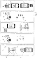
Fig. 1 ein Schema des erfindungsgemässen Verfahrens, -
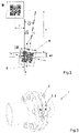
Fig. 2 ein Markierungspaar mit Master und Slave, -
Fig. 3 Beispiel einer Anordnungsmöglichkeit eines Markierungspaars, -
Fig. 4 Beispiel einer Anordnungsmöglichkeit eines Markierungspaars, -
Fig. 5 Beispiel einer Anordnungsmöglichkeit eines Markierungspaars, -
Fig. 6 Aufgezeigte Verschiebung in einer Rohrleitung und -
Fig. 7 Endgerät mit möglichen Anzeigen. -
Fig. 1 zeigt das erfindungsgemässe Verfahren schematisch. In Abschnitt A ist zu erkennen, dass Markierungen 3 an Komponenten 2 des Rohrleitungssystems 1 oder auch an Bauelementen 13, wie Wände, Pfeiler usw. angeordnet werden, wobei die Markierungen selbstverständlich auf jeder möglichen Komponente des Rohrleitungssystems 1 angeordnet werden können. In denFiguren 3 bis 5 sind weitere Möglichkeiten von Anordnung von Markierungen 3 welche vorzugsweise als QR-Code ausgebildet sind an Komponenten 2 des Rohrleitungssystems 1 offenbart, wobei diese Aufführung selbstverständlich nicht abschliessend ist. Zudem wird in A aufgeführt, dass die Markierung 3, welche vorzugsweise als QR-Code ausgebildet ist, erfasst oder gescannt oder fotografiert wird, vorzugsweise mit einem mobilen Endgerät 7 oder eine Digitalkamera 7. Daraus wird eine Basisaufnahme 4 erstellt, welche den Ausgangszustand der Rohrleitung 1 an dieser Position bzw. mit den erfassten Komponenten 2 und/oder Bauelementen 13 aufzeigt, dies ist dem Abschnitt B zu entnehmen. Wobei durch die Basisaufnahme 4 die exakte Position und Ausrichtung der beiden Markierungen 3 zueinander erfasst wird. Zudem werden den Markierungen 3 Eigenschaften und Daten zugewiesen und hinterlegt. Beispielsweise Eigenschaften der jeweiligen Komponente, Eigenschaften der Rohrleitung, Standort, etc.. Die Basisaufnahme 4 wird gespeichert vorzugsweise in einer Datenbank 5 oder einem sonstigen Speicherort, wobei es von Vorteil ist wenn die Möglichkeit eines Fernzugriffs besteht und diverse Anwender darauf zugreifen können, wodurch ein Speichern in einer Cloud auch denkbar ist. Um nun zu erkennen ob sich eine Veränderung oder Verschiebung im Rohrleitungssystem 1 ergeben hat, wird die Markierung erneut erfasst oder gescannt oder fotographiert, wie in Abschnitt C gezeigt. Es werden erneut die beiden Markierungen 3 also dasselbe Markierungspaar 8 erfasst, vorzugsweise wieder mit einem mobilen Endgerät oder einer Digitalkamera die mit einem Rechner verbunden werden kann. Mit Hilfe einer Recheneinheit wird autonom erkannt um welche Markierung 3 bzw. Markierungspaar 8 es sich handelt und zugleich ein Vergleich der Positionen der Markierungen zueinander durchgeführt, was dem Abschnitt D zu entnehmen ist. Zudem ist es von Vorteil, wenn die erneute Erfassung des Markierungspaares 8 als Folgeaufnahme 6 ebenfalls gespeichert wird, wie auch weitere Folgeaufnahmen 6 erstellt und gespeichert werden können, wodurch eine entstehende Verschiebung bzw. Veränderung des Rohrleitungssystems 1 bei den entsprechenden Komponenten 2 beobachtet werden kann.
Die ermittelten Werte ΔX, ΔY, ΔZ, θ der Verschiebung werden daraufhin ausgegeben 11, dies kann auch auf einem mobilen Endgerät 7 angezeigt werden oder auch durch ein anderes Anzeigegerät erfolgen, was in Abschnitt E dargestellt ist. Es kann aber auch auf eine visuelle Ausgabe der Werte verzichtet werden und die Werte werden gleich weiterverarbeitet bzw. für weitere Kalkulationen verwendet oder einfach vorerst nur gespeichert. Vorzugsweise kann mittels des erfindungsgemässen Verfahren auch eine Überwachung eines Rohrleitungssystems 1 erstellt werden, indem regelmässige Folgeaufnahmen 6 erfasst werden und automatisch die Verschiebung ermittelt wird aufgrund dessen auch ein Alarm hinterlegt werden kann, der beim Überschreiten oder Erreichen eines Wertes der Verschiebung ausgelöst wird. Dazu sollten Maximalwerte definiert und hinterlegt werden. Beim Auslösen des Alarms kann beispielsweise automatisch ein Verantwortlicher über ein mobiles Endgerät informiert werden wie auch andere bekannte Formen des Alarms denkbar sind. Zudem ist es vorteilhaft wenn dem Verfahren ein Algorithmus hinterlegt ist, der es ermöglicht aufgrund der ermittelten Werte der Verschiebung zwischen der Basisaufnahme und der Folgeaufnahme des Markierungspaares 8 eine Beurteilung der Verschiebung abzugeben und/oder eine Empfehlung wie die Verschiebung reduziert werden kann, bzw. was z.B. an der Befestigung 12 des Rohrleitungssystems zu verbessern ist oder andere Empfehlungen. - In
Fig. 2 ist aufgezeigt wie die Ermittlung der Werte ΔX, ΔY, ΔZ, θ vorzugsweise erfolgt. Dazu ist es vorteilhaft, wenn eine der beiden Markierungen als Master 9 definiert wird und die anderer des Markierungspaares 8 als Slave 10. Dadurch lässt sich die Verschiebung der Markierungen 3 zueinander gut in die Richtungen X, Y und Z definieren wie auch in eine Winkelverschiebung θ und berechnen, wobei hier nur die Richtungen X, Y und die Winkelverschiebung θ dargestellt sind, die Richtung Z ist hier die Tiefe und kann selbstverständlich genauso ermittelt werden. Es müssen auch nicht alle Werte ermittelt werden, manchmal sind zwei bereits ausreichend. Wie bereits erwähnt können auch Winkelverschiebungen θ erkannt werden. InFig. 2 ist aufgezeigt, dass sich die Folgeaufnahme 6 des Slaves 10 zur Basisaufnahme 4 (durch zwei breite Linien die sich kreuzen mit grauem QR-Code dargestellt) des Slaves 10 um ΔX, ΔY und eine Winkelverschiebungen θ verschoben hat. Diese Werte werden dann entsprechend ausgegeben und/oder auch gespeichert. Darauf kann eine Beurteilung der Lage erfolgen oder auch eine Empfehlung wie auch ein Alarm eingerichtet sein kann der beim Überschreiten eines bestimmten Werts auslöst. Als Beispiel ist inFig. 7 ein mobiles Endgerät 7 mit möglichen Ausgaben dargestellt. -
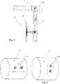
Fig. 3 zeigt eine Flanschkupplung als mögliche Komponente 2 der Rohrleitung 1 an deren Flanschen jeweils eine Markierung 3 angeordnet ist und die ein Markierungspaar 8 bilden.Fig. 4 zeigt eine an einem Bauelement 13 befestigte Rohrleitung 1 bei dem die Markierungen 3 auf einem Winkelstück und einem Rohr angebracht wurden. Die Markierungen 3 werden nach dem fertigen Verlegen des Rohrleitungssystems 1 angebracht, an welchen Komponenten 2 oder Bauelementen 13 entscheidet in der Regel der Installateur. In der Regel werden solche Komponenten 2 und Bauelemente 13 ausgewählt, bei denen eine Verschiebung bzw. Veränderung der Rohrleitung 1 gut erkennbar ist und sie durch ihre Lage oder durch ihren Einbau auch am ehesten dazu neigen und eine Gefahrenstelle für Leckagen darstellen. Üblich sind Befestigungselemente 12 die eine Rohrleitung 1 an einem Bauelement 13 befestigen.
Als weitere Einsatzmöglichkeit des erfindungsgemässen Verfahrens können Markierungen 3 bzw. Markierungspaare 8 auch an einem Rohr nebeneinander angeordnet werden, wie inFig. 5 dargestellt. Dadurch kann eine Ausdehnung oder ein Schrumpfen wie im ersten Bild erkannt werden oder eine Blähung des Rohres wie in der zweiten Abbildung derFig. 5
Fig. 6 zeigt das erfindungsgemässe System zur Erkennung einer Verschiebung oder Veränderung in einem installierten Rohrleitungssystem 1. Das System beinhaltet ein installiertes Rohrleitungssystem 1 mit Komponenten 2, Befestigungselemente 12 und Markierungen 3. Die Markierungen 3 welche vorzugsweise als QR-Code ausgebildet sind bilden jeweils ein Markierungspaar 8 welches in einer Basisaufnahme 4 erfasst ist. Die Basisaufnahme ist eine Abbildung des Ausgangszustands und wird dementsprechend gespeichert und als Vergleichswert hinterlegt. Zudem ist inFig. 6 ersichtlich, dass eine Veränderung einer Komponente 2 aufgetreten ist. Die erste Abbildung stellt die Basisaufnahme 4 dar und in der zweiten ist die Verschiebung durch die Werte ΔX und ΔY erkennbar, welche dann vorzugsweise zum Vergleich in einer Folgeaufnahme 6 erfasst werden. -
- 1
- Rohrleitungssystem
- 2
- Komponente
- 3
- Markierung
- 4
- Basisaufnahme Ausgangszustand
- 5
- Speicherort, Datenbank
- 6
- Folgeaufnahme
- 7
- Mobiles Endgerät oder Digitalkamera
- 8
- Markierungspaar
- 9
- Master
- 10
- Slave
- 11
- Ausgabe, Mitteilung, Alarm, Beurteilung, Empfehlung
- 12
- Befestigungselement
- 13
- Bauelement (Wände, Böden, Decken, Pfeiler usw.)
- 14
- Winkelverschiebung θ
Claims (12)
- Verfahren zur Erkennung von Verschiebungen in installierten Rohrleitungssystemen (1) und Identifizierung von Komponenten (2) und deren Eigenschaften, beinhaltend:• anordnen / anbringen einer Markierung (3) auf mindestens einer der Komponenten (2) des installierten Rohrleitungssystems (1),• erfassen / scannen / fotografieren der Markierung (3) und generieren einer Basisaufnahme (4) des Ausgangszustands,• der Markierung (3) Eigenschaften und Daten zuweisen und hinterlegen,• speichern der Basisaufnahme (4) an einem Speicherort (5),• erneutes erfassen / scannen / fotografieren der Markierung (3),• autonomes erkennen der Markierung (3) und vergleichen mit der gespeicherten Basisaufnahme (4) der entsprechenden Markierung (3),• ermitteln von Veränderungen oder Verschiebungen der Markierung (3),• Ausgabe (11) von ermittelten Werten (ΔX, ΔY, ΔZ, θ)
dadurch gekennzeichnet, dass mindestens zwei Markierungen so angeordnet sind, dass sie auf einer Basisaufnahme (4) gemeinsam erfasst werden. - Verfahren nach Anspruch 1, dadurch gekennzeichnet, dass beim erneuten erfassen / scannen / fotografieren der Markierung (3) eine Folgeaufnahme (6) erstellt wird.
- Verfahren nach Anspruch 1 oder 2, dadurch gekennzeichnet, dass die Markierung (3) durch ein QR-Code gebildet wird.
- Verfahren nach einem der Ansprüche 1 bis 3, dadurch gekennzeichnet, dass mindestens zwei Markierungen (3) an unterschiedlichen Komponenten (2) oder an einer Komponente (2) und einem Bauelement (13) angeordnet werden.
- Verfahren nach einem der Ansprüche 1 bis 4, dadurch gekennzeichnet, dass zwei Markierungen (3) angeordnet werden, wobei die Markierung (3) ein Paar (8) bilden, welches auf der Basisaufnahme (4) erfasst wird.
- Verfahren nach einem der Ansprüche 1 bis 5, dadurch gekennzeichnet, dass eine Beurteilung (11) der Verschiebung und/oder eine Empfehlung (11) zur Reduktion einer Verschiebung des Rohrleitungssystems (1) an der entsprechenden Stelle mit Hilfe der ermittelten Werte (ΔX, ΔY, ΔZ) erfolgt.
- Verfahren nach einem der Ansprüche 1 bis 6, dadurch gekennzeichnet, dass mittels der ermittelten Werte (ΔX, ΔY, ΔZ) und/oder Winkelverschiebungen θ und eines Algorithmus eine Beurteilung (11) der Verschiebung und/oder Empfehlung (11) zur Reduktion der Verschiebung erstellt wird.
- Verfahren nach einem der Ansprüche 1 bis 7, dadurch gekennzeichnet, dass das Erfassen / Scannen / Photographien mittels eines mobilen Endgerätes (7) oder einer Digitalkamera (7) erfolgt.
- System zur Erkennung von Verschiebungen in installierten Rohrleitungssystemen (1) und Identifizierung von Komponenten (2) und deren Eigenschaften, beinhaltend:ein installiertes Rohrleitungssystem (1), dessen Komponente (2),Befestigungselemente (12), Bauelemente (13) und Markierungen (3),dadurch gekennzeichnet, dass mindestens zwei Markierungen (3) am Rohrleitungssystem (1) angeordnet sind, wobei jeweils zwei Markierungen (3) ein Paar (8) bilden, wobei das Markierungspaar (8) in einer Basisaufnahme (4) erfasst ist.
- System nach Anspruch 9, dadurch gekennzeichnet, dass die Markierung (3) durch einen QR-Code gebildet ist.
- System nach einem der Ansprüche 9 oder 10, dadurch gekennzeichnet, dass jeweils eine Markierung (3) des Markierungspaares (8) jeweils auf einer Komponente (2) des Rohrleitungssystems (1) angeordnet ist oder auf einer Komponente (2) und auf einem Bauelement (13).
- System nach einem der Ansprüche 9 bis 11, dadurch gekennzeichnet, dass das System ein mobiles Endgerät (7) und/oder eine Digitalkamera (7) zum Erfassen / Scannen / Photographien der Markierung (3) beinhaltet.
Priority Applications (4)
| Application Number | Priority Date | Filing Date | Title |
|---|---|---|---|
| EP20208251.7A EP4001735B1 (de) | 2020-11-18 | 2020-11-18 | Überwachung von rohrleitungssystemen |
| AU2021258021A AU2021258021B2 (en) | 2020-11-18 | 2021-10-28 | Monitoring of pipeline systems |
| CA3138073A CA3138073C (en) | 2020-11-18 | 2021-11-08 | Monitoring of pipeline systems |
| US17/527,618 US12266095B2 (en) | 2020-11-18 | 2021-11-16 | Monitoring of pipeline systems |
Applications Claiming Priority (1)
| Application Number | Priority Date | Filing Date | Title |
|---|---|---|---|
| EP20208251.7A EP4001735B1 (de) | 2020-11-18 | 2020-11-18 | Überwachung von rohrleitungssystemen |
Publications (3)
| Publication Number | Publication Date |
|---|---|
| EP4001735A1 true EP4001735A1 (de) | 2022-05-25 |
| EP4001735B1 EP4001735B1 (de) | 2024-04-10 |
| EP4001735C0 EP4001735C0 (de) | 2024-04-10 |
Family
ID=73597759
Family Applications (1)
| Application Number | Title | Priority Date | Filing Date |
|---|---|---|---|
| EP20208251.7A Active EP4001735B1 (de) | 2020-11-18 | 2020-11-18 | Überwachung von rohrleitungssystemen |
Country Status (4)
| Country | Link |
|---|---|
| US (1) | US12266095B2 (de) |
| EP (1) | EP4001735B1 (de) |
| AU (1) | AU2021258021B2 (de) |
| CA (1) | CA3138073C (de) |
Cited By (1)
| Publication number | Priority date | Publication date | Assignee | Title |
|---|---|---|---|---|
| WO2025124642A1 (de) | 2023-12-14 | 2025-06-19 | Hochschule Kaiserslautern, Körperschaft des öffentlichen Rechts | Anschlusssystem |
Families Citing this family (4)
| Publication number | Priority date | Publication date | Assignee | Title |
|---|---|---|---|---|
| CN115234845B (zh) * | 2022-07-26 | 2024-07-23 | 西安石油大学 | 基于投影模型的油气管道内壁缺陷图像可视化检测方法 |
| CN119677983A (zh) * | 2022-09-22 | 2025-03-21 | 诺玛美国控股有限责任公司 | 查明流体管路组件中的一个或多个连接状态 |
| CN117078635A (zh) * | 2023-08-21 | 2023-11-17 | 北京理工大学 | 管接头松动状态检测方法、装置、设备和可读存储介质 |
| WO2025213202A1 (de) * | 2024-04-09 | 2025-10-16 | Henn Gmbh & Co Kg. | Verbindungssystem, ausleseeinrichtung für ein verbindungssystem und validierungverfahren für ein verbindungssystem |
Citations (4)
| Publication number | Priority date | Publication date | Assignee | Title |
|---|---|---|---|---|
| US20010029989A1 (en) | 2000-02-17 | 2001-10-18 | Paz German N. | Pipeline identification and positioning system |
| US20180350273A1 (en) * | 2014-05-01 | 2018-12-06 | James W. Walley, JR. | Color Coding System for PVC Pipes and Couplings |
| US10443772B2 (en) * | 2013-10-09 | 2019-10-15 | Kubota Corporation | Pipe joint structure, seal member, assembled condition management method for pipe joint, and assembled condition management device for pipe joint |
| EP3567294A1 (de) * | 2018-05-08 | 2019-11-13 | Witzenmann GmbH | Bewegliches bauteil aus metall |
Family Cites Families (9)
| Publication number | Priority date | Publication date | Assignee | Title |
|---|---|---|---|---|
| US5095365A (en) * | 1989-10-20 | 1992-03-10 | Hitachi, Ltd. | System for monitoring operating state of devices according to their degree of importance |
| KR100553410B1 (ko) * | 2003-12-31 | 2006-02-20 | 조선영 | 배관의 3축 변위 계측장치 및 모니터링 시스템 |
| JP6264834B2 (ja) * | 2013-10-24 | 2018-01-24 | 富士通株式会社 | ガイド方法、情報処理装置およびガイドプログラム |
| WO2015072188A1 (ja) * | 2013-11-15 | 2015-05-21 | 株式会社Ihi | 検査システム |
| KR102085411B1 (ko) * | 2014-12-18 | 2020-03-05 | 가부시키가이샤 아이에이치아이 | 검사 프로브 |
| JP2018205834A (ja) * | 2017-05-30 | 2018-12-27 | マークテック株式会社 | 二次元コードのマーキング装置、及び二次元コードのマーキング方法 |
| CN107449470A (zh) * | 2017-09-18 | 2017-12-08 | 尤立荣 | 基于视觉检测的微流量传感装置 |
| TWI779268B (zh) * | 2019-02-28 | 2022-10-01 | 日商Ihi股份有限公司 | 超音波探傷裝置 |
| CN209765567U (zh) * | 2019-03-07 | 2019-12-10 | 邬光红 | 城市供水智能管理系统 |
-
2020
- 2020-11-18 EP EP20208251.7A patent/EP4001735B1/de active Active
-
2021
- 2021-10-28 AU AU2021258021A patent/AU2021258021B2/en active Active
- 2021-11-08 CA CA3138073A patent/CA3138073C/en active Active
- 2021-11-16 US US17/527,618 patent/US12266095B2/en active Active
Patent Citations (4)
| Publication number | Priority date | Publication date | Assignee | Title |
|---|---|---|---|---|
| US20010029989A1 (en) | 2000-02-17 | 2001-10-18 | Paz German N. | Pipeline identification and positioning system |
| US10443772B2 (en) * | 2013-10-09 | 2019-10-15 | Kubota Corporation | Pipe joint structure, seal member, assembled condition management method for pipe joint, and assembled condition management device for pipe joint |
| US20180350273A1 (en) * | 2014-05-01 | 2018-12-06 | James W. Walley, JR. | Color Coding System for PVC Pipes and Couplings |
| EP3567294A1 (de) * | 2018-05-08 | 2019-11-13 | Witzenmann GmbH | Bewegliches bauteil aus metall |
Cited By (1)
| Publication number | Priority date | Publication date | Assignee | Title |
|---|---|---|---|---|
| WO2025124642A1 (de) | 2023-12-14 | 2025-06-19 | Hochschule Kaiserslautern, Körperschaft des öffentlichen Rechts | Anschlusssystem |
Also Published As
| Publication number | Publication date |
|---|---|
| EP4001735B1 (de) | 2024-04-10 |
| US20220156907A1 (en) | 2022-05-19 |
| AU2021258021B2 (en) | 2023-02-02 |
| CA3138073C (en) | 2025-09-09 |
| AU2021258021A1 (en) | 2022-06-02 |
| CA3138073A1 (en) | 2022-05-18 |
| EP4001735C0 (de) | 2024-04-10 |
| US12266095B2 (en) | 2025-04-01 |
Similar Documents
| Publication | Publication Date | Title |
|---|---|---|
| EP4001735B1 (de) | Überwachung von rohrleitungssystemen | |
| EP2824525B1 (de) | Verfahren und Einrichtung zur Bestimmung der Position von Betriebsmitteln einer industriellen Automatisierungsanordnung | |
| DE102020134680B4 (de) | Verfahren und Anordnung zur Qualitätsprüfung eines Objekts | |
| DE102005021735B4 (de) | Videoüberwachungssystem | |
| WO2015028294A1 (de) | Überwachungsanlage sowie verfahren zur darstellung eines überwachungsbereichs | |
| WO2005091245A1 (de) | Verfahren und warnvorrichtung zum grafischen aufbereiten eines bildes einer kamera | |
| DE102020109357A1 (de) | Verfahren zur Bewertung der Einbauposition eines Messgeräts in einer Anlage, Augmented-Reality-Gerät und Verfahren zum Einbau eines Messgeräts | |
| EP3628993A1 (de) | Verfahren zur ermittlung des auftretens einer störstelle einer leitung mittels schätzung | |
| EP3387375B1 (de) | Verfahren zur erstellung einer tiefenkarte | |
| WO2023209145A1 (de) | Detektionsverfahren und system zur detektion eines bauwerkteils auf einer baustelle | |
| DE10049366A1 (de) | Verfahren zum Überwachen eines Sicherheitsbereichs und entsprechendes System | |
| EP3918882B1 (de) | Verfahren zur unterstützung der installation eines sensors bzw. einer leuchte in beleuchtungssystemen | |
| DE102014012693A1 (de) | System zur Positions-und Lagebestimmung von Objekten | |
| WO2008131826A1 (de) | Verfahren zum generieren von zielmarkierenden peiltracks | |
| EP2219155A2 (de) | Vorrichtung, Verfahren und Computerprogramm zur Segmentierung eines Objektes in einem Bild, und Videoüberwachungssystem | |
| DE102013218299A1 (de) | Verfahren zum Detektieren eines Schadens eines Fahrzeugs anhand eines Prüfbilds, entsprechendes System und Computerprogrammprodukt | |
| DE102019220364A1 (de) | Kalibriereinrichtung und Verfahren zum Kalibrieren einer Vorrichtung | |
| DE4042511C2 (de) | Überwachungssystem für Störungen | |
| EP3352111B1 (de) | Verfahren zum erkennen von kritischen ereignissen | |
| EP3928056B1 (de) | Computerimplementiertes verfahren, computerprogrammprodukt und system zum bestimmen von installationsdaten betreffend die lage zumindest einer zu installierenden wassertechnischen einrichtung | |
| EP3107047A1 (de) | System und verfahren zur ortung und darstellung von inspektionsdaten | |
| DE102023116812B4 (de) | Erfassungsanordnung und Verfahren zur Steuerung eines Betriebs einer Erfassungsanordnung | |
| EP3671540A1 (de) | Verfahren und vorrichtung zur auslösung einer aktion | |
| DE102019211102A1 (de) | Verfahren, Vorrichtung und Computerprogramm zum Auswerten von Ampelinformationen über eine Ampelanlage | |
| DE10024718C2 (de) | Verfahren zur digitalen Erfassung von Oberflächen von Flachdächern |
Legal Events
| Date | Code | Title | Description |
|---|---|---|---|
| PUAI | Public reference made under article 153(3) epc to a published international application that has entered the european phase |
Free format text: ORIGINAL CODE: 0009012 |
|
| STAA | Information on the status of an ep patent application or granted ep patent |
Free format text: STATUS: THE APPLICATION HAS BEEN PUBLISHED |
|
| AK | Designated contracting states |
Kind code of ref document: A1 Designated state(s): AL AT BE BG CH CY CZ DE DK EE ES FI FR GB GR HR HU IE IS IT LI LT LU LV MC MK MT NL NO PL PT RO RS SE SI SK SM TR |
|
| STAA | Information on the status of an ep patent application or granted ep patent |
Free format text: STATUS: REQUEST FOR EXAMINATION WAS MADE |
|
| 17P | Request for examination filed |
Effective date: 20221031 |
|
| RBV | Designated contracting states (corrected) |
Designated state(s): AL AT BE BG CH CY CZ DE DK EE ES FI FR GB GR HR HU IE IS IT LI LT LU LV MC MK MT NL NO PL PT RO RS SE SI SK SM TR |
|
| P01 | Opt-out of the competence of the unified patent court (upc) registered |
Effective date: 20230529 |
|
| GRAJ | Information related to disapproval of communication of intention to grant by the applicant or resumption of examination proceedings by the epo deleted |
Free format text: ORIGINAL CODE: EPIDOSDIGR1 |
|
| GRAP | Despatch of communication of intention to grant a patent |
Free format text: ORIGINAL CODE: EPIDOSNIGR1 |
|
| GRAP | Despatch of communication of intention to grant a patent |
Free format text: ORIGINAL CODE: EPIDOSNIGR1 |
|
| STAA | Information on the status of an ep patent application or granted ep patent |
Free format text: STATUS: GRANT OF PATENT IS INTENDED |
|
| INTG | Intention to grant announced |
Effective date: 20231122 |
|
| GRAS | Grant fee paid |
Free format text: ORIGINAL CODE: EPIDOSNIGR3 |
|
| P04 | Withdrawal of opt-out of the competence of the unified patent court (upc) registered |
Effective date: 20240126 |
|
| GRAA | (expected) grant |
Free format text: ORIGINAL CODE: 0009210 |
|
| STAA | Information on the status of an ep patent application or granted ep patent |
Free format text: STATUS: THE PATENT HAS BEEN GRANTED |
|
| AK | Designated contracting states |
Kind code of ref document: B1 Designated state(s): AL AT BE BG CH CY CZ DE DK EE ES FI FR GB GR HR HU IE IS IT LI LT LU LV MC MK MT NL NO PL PT RO RS SE SI SK SM TR |
|
| REG | Reference to a national code |
Ref country code: GB Ref legal event code: FG4D Free format text: NOT ENGLISH |
|
| REG | Reference to a national code |
Ref country code: CH Ref legal event code: EP |
|
| REG | Reference to a national code |
Ref country code: DE Ref legal event code: R096 Ref document number: 502020007608 Country of ref document: DE |
|
| REG | Reference to a national code |
Ref country code: IE Ref legal event code: FG4D Free format text: LANGUAGE OF EP DOCUMENT: GERMAN |
|
| U01 | Request for unitary effect filed |
Effective date: 20240411 |
|
| U07 | Unitary effect registered |
Designated state(s): AT BE BG DE DK EE FI FR IT LT LU LV MT NL PT SE SI Effective date: 20240422 |
|
| PG25 | Lapsed in a contracting state [announced via postgrant information from national office to epo] |
Ref country code: IS Free format text: LAPSE BECAUSE OF FAILURE TO SUBMIT A TRANSLATION OF THE DESCRIPTION OR TO PAY THE FEE WITHIN THE PRESCRIBED TIME-LIMIT Effective date: 20240810 |
|
| PG25 | Lapsed in a contracting state [announced via postgrant information from national office to epo] |
Ref country code: HR Free format text: LAPSE BECAUSE OF FAILURE TO SUBMIT A TRANSLATION OF THE DESCRIPTION OR TO PAY THE FEE WITHIN THE PRESCRIBED TIME-LIMIT Effective date: 20240410 |
|
| PG25 | Lapsed in a contracting state [announced via postgrant information from national office to epo] |
Ref country code: GR Free format text: LAPSE BECAUSE OF FAILURE TO SUBMIT A TRANSLATION OF THE DESCRIPTION OR TO PAY THE FEE WITHIN THE PRESCRIBED TIME-LIMIT Effective date: 20240711 |
|
| PG25 | Lapsed in a contracting state [announced via postgrant information from national office to epo] |
Ref country code: ES Free format text: LAPSE BECAUSE OF FAILURE TO SUBMIT A TRANSLATION OF THE DESCRIPTION OR TO PAY THE FEE WITHIN THE PRESCRIBED TIME-LIMIT Effective date: 20240410 |
|
| PG25 | Lapsed in a contracting state [announced via postgrant information from national office to epo] |
Ref country code: PL Free format text: LAPSE BECAUSE OF FAILURE TO SUBMIT A TRANSLATION OF THE DESCRIPTION OR TO PAY THE FEE WITHIN THE PRESCRIBED TIME-LIMIT Effective date: 20240410 |
|
| PG25 | Lapsed in a contracting state [announced via postgrant information from national office to epo] |
Ref country code: PL Free format text: LAPSE BECAUSE OF FAILURE TO SUBMIT A TRANSLATION OF THE DESCRIPTION OR TO PAY THE FEE WITHIN THE PRESCRIBED TIME-LIMIT Effective date: 20240410 Ref country code: NO Free format text: LAPSE BECAUSE OF FAILURE TO SUBMIT A TRANSLATION OF THE DESCRIPTION OR TO PAY THE FEE WITHIN THE PRESCRIBED TIME-LIMIT Effective date: 20240710 Ref country code: IS Free format text: LAPSE BECAUSE OF FAILURE TO SUBMIT A TRANSLATION OF THE DESCRIPTION OR TO PAY THE FEE WITHIN THE PRESCRIBED TIME-LIMIT Effective date: 20240810 Ref country code: HR Free format text: LAPSE BECAUSE OF FAILURE TO SUBMIT A TRANSLATION OF THE DESCRIPTION OR TO PAY THE FEE WITHIN THE PRESCRIBED TIME-LIMIT Effective date: 20240410 Ref country code: GR Free format text: LAPSE BECAUSE OF FAILURE TO SUBMIT A TRANSLATION OF THE DESCRIPTION OR TO PAY THE FEE WITHIN THE PRESCRIBED TIME-LIMIT Effective date: 20240711 Ref country code: ES Free format text: LAPSE BECAUSE OF FAILURE TO SUBMIT A TRANSLATION OF THE DESCRIPTION OR TO PAY THE FEE WITHIN THE PRESCRIBED TIME-LIMIT Effective date: 20240410 Ref country code: RS Free format text: LAPSE BECAUSE OF FAILURE TO SUBMIT A TRANSLATION OF THE DESCRIPTION OR TO PAY THE FEE WITHIN THE PRESCRIBED TIME-LIMIT Effective date: 20240710 |
|
| U20 | Renewal fee for the european patent with unitary effect paid |
Year of fee payment: 5 Effective date: 20241126 |
|
| REG | Reference to a national code |
Ref country code: DE Ref legal event code: R097 Ref document number: 502020007608 Country of ref document: DE |
|
| PG25 | Lapsed in a contracting state [announced via postgrant information from national office to epo] |
Ref country code: CZ Free format text: LAPSE BECAUSE OF FAILURE TO SUBMIT A TRANSLATION OF THE DESCRIPTION OR TO PAY THE FEE WITHIN THE PRESCRIBED TIME-LIMIT Effective date: 20240410 |
|
| PG25 | Lapsed in a contracting state [announced via postgrant information from national office to epo] |
Ref country code: RO Free format text: LAPSE BECAUSE OF FAILURE TO SUBMIT A TRANSLATION OF THE DESCRIPTION OR TO PAY THE FEE WITHIN THE PRESCRIBED TIME-LIMIT Effective date: 20240410 Ref country code: SK Free format text: LAPSE BECAUSE OF FAILURE TO SUBMIT A TRANSLATION OF THE DESCRIPTION OR TO PAY THE FEE WITHIN THE PRESCRIBED TIME-LIMIT Effective date: 20240410 |
|
| PG25 | Lapsed in a contracting state [announced via postgrant information from national office to epo] |
Ref country code: SM Free format text: LAPSE BECAUSE OF FAILURE TO SUBMIT A TRANSLATION OF THE DESCRIPTION OR TO PAY THE FEE WITHIN THE PRESCRIBED TIME-LIMIT Effective date: 20240410 |
|
| PG25 | Lapsed in a contracting state [announced via postgrant information from national office to epo] |
Ref country code: SM Free format text: LAPSE BECAUSE OF FAILURE TO SUBMIT A TRANSLATION OF THE DESCRIPTION OR TO PAY THE FEE WITHIN THE PRESCRIBED TIME-LIMIT Effective date: 20240410 Ref country code: SK Free format text: LAPSE BECAUSE OF FAILURE TO SUBMIT A TRANSLATION OF THE DESCRIPTION OR TO PAY THE FEE WITHIN THE PRESCRIBED TIME-LIMIT Effective date: 20240410 Ref country code: RO Free format text: LAPSE BECAUSE OF FAILURE TO SUBMIT A TRANSLATION OF THE DESCRIPTION OR TO PAY THE FEE WITHIN THE PRESCRIBED TIME-LIMIT Effective date: 20240410 Ref country code: CZ Free format text: LAPSE BECAUSE OF FAILURE TO SUBMIT A TRANSLATION OF THE DESCRIPTION OR TO PAY THE FEE WITHIN THE PRESCRIBED TIME-LIMIT Effective date: 20240410 |
|
| PLBE | No opposition filed within time limit |
Free format text: ORIGINAL CODE: 0009261 |
|
| STAA | Information on the status of an ep patent application or granted ep patent |
Free format text: STATUS: NO OPPOSITION FILED WITHIN TIME LIMIT |
|
| 26N | No opposition filed |
Effective date: 20250113 |
|
| PG25 | Lapsed in a contracting state [announced via postgrant information from national office to epo] |
Ref country code: MC Free format text: LAPSE BECAUSE OF FAILURE TO SUBMIT A TRANSLATION OF THE DESCRIPTION OR TO PAY THE FEE WITHIN THE PRESCRIBED TIME-LIMIT Effective date: 20240410 |
|
| GBPC | Gb: european patent ceased through non-payment of renewal fee |
Effective date: 20241118 |
|
| PG25 | Lapsed in a contracting state [announced via postgrant information from national office to epo] |
Ref country code: GB Free format text: LAPSE BECAUSE OF NON-PAYMENT OF DUE FEES Effective date: 20241118 |
|
| PG25 | Lapsed in a contracting state [announced via postgrant information from national office to epo] |
Ref country code: IE Free format text: LAPSE BECAUSE OF NON-PAYMENT OF DUE FEES Effective date: 20241118 |
|
| REG | Reference to a national code |
Ref country code: CH Ref legal event code: U11 Free format text: ST27 STATUS EVENT CODE: U-0-0-U10-U11 (AS PROVIDED BY THE NATIONAL OFFICE) Effective date: 20251201 |
|
| U20 | Renewal fee for the european patent with unitary effect paid |
Year of fee payment: 6 Effective date: 20251127 |
|
| PGFP | Annual fee paid to national office [announced via postgrant information from national office to epo] |
Ref country code: CH Payment date: 20251201 Year of fee payment: 6 |
|
| PG25 | Lapsed in a contracting state [announced via postgrant information from national office to epo] |
Ref country code: HU Free format text: LAPSE BECAUSE OF FAILURE TO SUBMIT A TRANSLATION OF THE DESCRIPTION OR TO PAY THE FEE WITHIN THE PRESCRIBED TIME-LIMIT; INVALID AB INITIO Effective date: 20201118 |
|
| PG25 | Lapsed in a contracting state [announced via postgrant information from national office to epo] |
Ref country code: CY Free format text: LAPSE BECAUSE OF FAILURE TO SUBMIT A TRANSLATION OF THE DESCRIPTION OR TO PAY THE FEE WITHIN THE PRESCRIBED TIME-LIMIT; INVALID AB INITIO Effective date: 20201118 |