EP4001739A1 - Luminaire pourvu de composants de luminaire intégrés - Google Patents
Luminaire pourvu de composants de luminaire intégrés Download PDFInfo
- Publication number
- EP4001739A1 EP4001739A1 EP21208673.0A EP21208673A EP4001739A1 EP 4001739 A1 EP4001739 A1 EP 4001739A1 EP 21208673 A EP21208673 A EP 21208673A EP 4001739 A1 EP4001739 A1 EP 4001739A1
- Authority
- EP
- European Patent Office
- Prior art keywords
- lamp
- housing
- electrical
- components
- electronic
- Prior art date
- Legal status (The legal status is an assumption and is not a legal conclusion. Google has not performed a legal analysis and makes no representation as to the accuracy of the status listed.)
- Granted
Links
Images




Classifications
-
- F—MECHANICAL ENGINEERING; LIGHTING; HEATING; WEAPONS; BLASTING
- F21—LIGHTING
- F21V—FUNCTIONAL FEATURES OR DETAILS OF LIGHTING DEVICES OR SYSTEMS THEREOF; STRUCTURAL COMBINATIONS OF LIGHTING DEVICES WITH OTHER ARTICLES, NOT OTHERWISE PROVIDED FOR
- F21V23/00—Arrangement of electric circuit elements in or on lighting devices
- F21V23/003—Arrangement of electric circuit elements in or on lighting devices the elements being electronics drivers or controllers for operating the light source, e.g. for a LED array
- F21V23/007—Arrangement of electric circuit elements in or on lighting devices the elements being electronics drivers or controllers for operating the light source, e.g. for a LED array enclosed in a casing
- F21V23/009—Arrangement of electric circuit elements in or on lighting devices the elements being electronics drivers or controllers for operating the light source, e.g. for a LED array enclosed in a casing the casing being inside the housing of the lighting device
-
- F—MECHANICAL ENGINEERING; LIGHTING; HEATING; WEAPONS; BLASTING
- F21—LIGHTING
- F21S—NON-PORTABLE LIGHTING DEVICES; SYSTEMS THEREOF; VEHICLE LIGHTING DEVICES SPECIALLY ADAPTED FOR VEHICLE EXTERIORS
- F21S8/00—Lighting devices intended for fixed installation
- F21S8/04—Lighting devices intended for fixed installation intended only for mounting on a ceiling or the like overhead structures
- F21S8/043—Lighting devices intended for fixed installation intended only for mounting on a ceiling or the like overhead structures mounted by means of a rigid support, e.g. bracket or arm
-
- F—MECHANICAL ENGINEERING; LIGHTING; HEATING; WEAPONS; BLASTING
- F21—LIGHTING
- F21S—NON-PORTABLE LIGHTING DEVICES; SYSTEMS THEREOF; VEHICLE LIGHTING DEVICES SPECIALLY ADAPTED FOR VEHICLE EXTERIORS
- F21S8/00—Lighting devices intended for fixed installation
- F21S8/04—Lighting devices intended for fixed installation intended only for mounting on a ceiling or the like overhead structures
- F21S8/06—Lighting devices intended for fixed installation intended only for mounting on a ceiling or the like overhead structures by suspension
-
- F—MECHANICAL ENGINEERING; LIGHTING; HEATING; WEAPONS; BLASTING
- F21—LIGHTING
- F21V—FUNCTIONAL FEATURES OR DETAILS OF LIGHTING DEVICES OR SYSTEMS THEREOF; STRUCTURAL COMBINATIONS OF LIGHTING DEVICES WITH OTHER ARTICLES, NOT OTHERWISE PROVIDED FOR
- F21V15/00—Protecting lighting devices from damage
- F21V15/01—Housings, e.g. material or assembling of housing parts
-
- F—MECHANICAL ENGINEERING; LIGHTING; HEATING; WEAPONS; BLASTING
- F21—LIGHTING
- F21V—FUNCTIONAL FEATURES OR DETAILS OF LIGHTING DEVICES OR SYSTEMS THEREOF; STRUCTURAL COMBINATIONS OF LIGHTING DEVICES WITH OTHER ARTICLES, NOT OTHERWISE PROVIDED FOR
- F21V31/00—Gas-tight or water-tight arrangements
- F21V31/005—Sealing arrangements therefor
-
- F—MECHANICAL ENGINEERING; LIGHTING; HEATING; WEAPONS; BLASTING
- F21—LIGHTING
- F21V—FUNCTIONAL FEATURES OR DETAILS OF LIGHTING DEVICES OR SYSTEMS THEREOF; STRUCTURAL COMBINATIONS OF LIGHTING DEVICES WITH OTHER ARTICLES, NOT OTHERWISE PROVIDED FOR
- F21V17/00—Fastening of component parts of lighting devices, e.g. shades, globes, refractors, reflectors, filters, screens, grids or protective cages
- F21V17/10—Fastening of component parts of lighting devices, e.g. shades, globes, refractors, reflectors, filters, screens, grids or protective cages characterised by specific fastening means or way of fastening
- F21V17/12—Fastening of component parts of lighting devices, e.g. shades, globes, refractors, reflectors, filters, screens, grids or protective cages characterised by specific fastening means or way of fastening by screwing
-
- F—MECHANICAL ENGINEERING; LIGHTING; HEATING; WEAPONS; BLASTING
- F21—LIGHTING
- F21V—FUNCTIONAL FEATURES OR DETAILS OF LIGHTING DEVICES OR SYSTEMS THEREOF; STRUCTURAL COMBINATIONS OF LIGHTING DEVICES WITH OTHER ARTICLES, NOT OTHERWISE PROVIDED FOR
- F21V23/00—Arrangement of electric circuit elements in or on lighting devices
- F21V23/001—Arrangement of electric circuit elements in or on lighting devices the elements being electrical wires or cables
- F21V23/002—Arrangements of cables or conductors inside a lighting device, e.g. means for guiding along parts of the housing or in a pivoting arm
-
- F—MECHANICAL ENGINEERING; LIGHTING; HEATING; WEAPONS; BLASTING
- F21—LIGHTING
- F21V—FUNCTIONAL FEATURES OR DETAILS OF LIGHTING DEVICES OR SYSTEMS THEREOF; STRUCTURAL COMBINATIONS OF LIGHTING DEVICES WITH OTHER ARTICLES, NOT OTHERWISE PROVIDED FOR
- F21V23/00—Arrangement of electric circuit elements in or on lighting devices
- F21V23/02—Arrangement of electric circuit elements in or on lighting devices the elements being transformers, impedances or power supply units, e.g. a transformer with a rectifier
- F21V23/023—Power supplies in a casing
-
- F—MECHANICAL ENGINEERING; LIGHTING; HEATING; WEAPONS; BLASTING
- F21—LIGHTING
- F21V—FUNCTIONAL FEATURES OR DETAILS OF LIGHTING DEVICES OR SYSTEMS THEREOF; STRUCTURAL COMBINATIONS OF LIGHTING DEVICES WITH OTHER ARTICLES, NOT OTHERWISE PROVIDED FOR
- F21V29/00—Protecting lighting devices from thermal damage; Cooling or heating arrangements specially adapted for lighting devices or systems
- F21V29/50—Cooling arrangements
- F21V29/70—Cooling arrangements characterised by passive heat-dissipating elements, e.g. heat-sinks
- F21V29/83—Cooling arrangements characterised by passive heat-dissipating elements, e.g. heat-sinks the elements having apertures, ducts or channels, e.g. heat radiation holes
-
- F—MECHANICAL ENGINEERING; LIGHTING; HEATING; WEAPONS; BLASTING
- F21—LIGHTING
- F21V—FUNCTIONAL FEATURES OR DETAILS OF LIGHTING DEVICES OR SYSTEMS THEREOF; STRUCTURAL COMBINATIONS OF LIGHTING DEVICES WITH OTHER ARTICLES, NOT OTHERWISE PROVIDED FOR
- F21V5/00—Refractors for light sources
- F21V5/007—Array of lenses or refractors for a cluster of light sources, e.g. for arrangement of multiple light sources in one plane
-
- F—MECHANICAL ENGINEERING; LIGHTING; HEATING; WEAPONS; BLASTING
- F21—LIGHTING
- F21W—INDEXING SCHEME ASSOCIATED WITH SUBCLASSES F21K, F21L, F21S and F21V, RELATING TO USES OR APPLICATIONS OF LIGHTING DEVICES OR SYSTEMS
- F21W2131/00—Use or application of lighting devices or systems not provided for in codes F21W2102/00-F21W2121/00
- F21W2131/40—Lighting for industrial, commercial, recreational or military use
-
- F—MECHANICAL ENGINEERING; LIGHTING; HEATING; WEAPONS; BLASTING
- F21—LIGHTING
- F21Y—INDEXING SCHEME ASSOCIATED WITH SUBCLASSES F21K, F21L, F21S and F21V, RELATING TO THE FORM OR THE KIND OF THE LIGHT SOURCES OR OF THE COLOUR OF THE LIGHT EMITTED
- F21Y2105/00—Planar light sources
- F21Y2105/10—Planar light sources comprising a two-dimensional [2D] array of point-like light-generating elements
-
- F—MECHANICAL ENGINEERING; LIGHTING; HEATING; WEAPONS; BLASTING
- F21—LIGHTING
- F21Y—INDEXING SCHEME ASSOCIATED WITH SUBCLASSES F21K, F21L, F21S and F21V, RELATING TO THE FORM OR THE KIND OF THE LIGHT SOURCES OR OF THE COLOUR OF THE LIGHT EMITTED
- F21Y2115/00—Light-generating elements of semiconductor light sources
- F21Y2115/10—Light-emitting diodes [LED]
Definitions
- the present invention relates to a lamp which is designed to efficiently dissipate the heat given off by the lamp components during operation of the lamp.
- the present invention relates to a so-called high-bay lamp.
- Highbay lights are lights that are used, for example, to illuminate larger halls or industrial complexes.
- the lamps are usually arranged at a relatively large distance from the floor, which is why there is a requirement that the lamp generates light with high intensity, which is then radiated onto the area below, for example a hall.
- relatively powerful lamps are used in such lights, which then have to be stored in a suitable manner, whereby care must be taken to ensure that on the one hand the heat generated during operation of the lamps is dissipated in a suitable manner and on the other hand the lamps are protected from external influences, in particular are protected from moisture and/or dust.
- a lamp of the type described above is, for example, from WO 2014/086770 A1 known to the applicant.
- the lamp described here is essentially formed by an aluminum die-cast body, which has large-area cooling rib structures and cooling channels for dissipating the high heat generated during operation of the lamp.
- Equipment is positioned centrally between two elongated LED arrays, with the design of the die-cast body being such that air can also flow around a centrally located housing in which the equipment is accommodated, in order to enable sufficient heat dissipation.
- By using appropriate cooling air openings a thermal decoupling between the housing for the equipment and the areas of the lamp body in which the lamps are arranged is also largely achieved.
- a trough-shaped lamp housing is used, which is formed by a one-piece and correspondingly deformed sheet metal part, with the housing base having areas for accommodating lamp components, for example the LED lamps and an associated control gear.
- the receiving areas are closed on all sides in order to efficiently protect the corresponding components from external influences.
- the design of the lamp housing and the cover is such that cooling air flows around those areas of the lamp that are subject to high thermal loads during operation in order to be able to efficiently dissipate the heat generated.
- the lights known from the prior art have proven themselves many times over and are characterized by their excellent light output and at the same time high operational reliability, which is due in particular to the optimized design of the respective light housing.
- the cost of realizing the lamp housing is relatively high.
- the use of one or more die-cast aluminum bodies is required, while in the other case, a one-piece housing formed from sheet metal is used. In this case too, however, relatively complex processing of the sheet metal part is required.
- the present invention is therefore based on the object of specifying a way of providing a lamp that is comparable in terms of its photometric properties, but in which the cost of manufacture and assembly is reduced and, despite everything, the heat generated during operation can be efficiently dissipated becomes.
- the lamp housing is again realized in the form of a one-piece component, which is preferably designed as a sheet metal part.
- a sheet metal part Compared to the relatively complex shape of the sheet metal part, as mentioned in the above WO 2020/228997 A1 is described, however, it is now provided that the corresponding sheet metal part only has to be deformed minimally.
- the housing base of the lamp housing then being completely flat on its side facing the interior of the lamp.
- the lamp housing is formed from at least two trough-shaped partial lamp housings, each of which has a housing base and a housing wall that runs laterally around the housing base.
- the housing base of each lamp part housing forms a flat area for accommodating electrical and/or electronic lamp components, the trough-shaped lamp part housings then being connected to one housing wall directly or indirectly via at least one connecting element. Due to the fact that the housing is formed by several light housing parts, which are then joined together in a corresponding manner, the overall effort involved in producing the light can also be reduced, since the light housing parts, which are preferably made of sheet metal, compared to those from the prior art Technology known solutions can be made relatively easily. In spite of everything, the luminaire housing achieved overall can in turn fulfill all functions, as is also the case with the luminaires in the prior art.
- each lamp part housing has a ring-like seal, which in each case encloses the associated area for accommodating electrical and/or electronic lamp components.
- the covers are designed in such a way that when they are mounted on the housing, they are closed all the way around the respective seal.
- the covers thus have circumferential webs which, in terms of their shape, correspond to the respective seals and touch the seals or dip into the seals with their end regions in the assembled state. This prevents dust and/or moisture from penetrating into the corresponding accommodation spaces for the electrical and/or electronic lighting components.
- the lamp has a frame-like holding element which is connected to the lamp housing in such a way that it presses the covers into contact with the associated seal.
- this holding element is responsible for closing the lamp housing - regardless of whether it is designed according to the first variant according to the invention or the second variant according to the invention - towards the front or in the light emission direction in order to close off the interior space in which the electrical and/or electronic lighting components are arranged to enclose safely.
- the cover is formed by a separate component, which is placed in the holding element in a suitable manner and is then attached to the lamp housing with its help.
- the cover is formed by a separate component which can be fastened to the holding element fastened to the lamp housing, in particular screwed to it.
- the cover is designed in such a way that it can be completely removed from the lamp or attached to it separately from the holding element. This can then be used, for example, to open a specific receiving area separately from other receiving areas of the lamp in order to service or, if necessary, replace the electrical and/or electronic components located therein.
- Such a cover lends itself, for example, in particular for the receiving area that is used to store an operating device or other power supply means.
- a third variant could consist in at least one cover being an integral part of the holding element.
- This configuration would be particularly advantageous if it is not desired for the end user to open the corresponding receiving area in a simple manner. This would then require a complete removal of the frame-like holding element, so that access to the corresponding receiving area can only be achieved here with increased effort or not at all.
- this advantage also results from the first variant, in which the cover is inserted accordingly into the holding element.
- At least one of the covers used here preferably has an optical system for influencing the light from illuminants.
- these optics can be an integral part of the corresponding cover, which is then of course formed from a light-transmitting material, or can be formed by a separate component that is inserted into the cover.
- the lamp according to the present invention has several areas in which electrical and/or electronic lamp components are arranged, it would be advantageous if these areas are at least partially thermally decoupled from one another in order to transfer the heat from one area to the other area as much as possible to suppress.
- the housing preferably has elongate through-openings which extend between two adjacent areas for accommodating electrical and/or electronic lighting components.
- the openings can be punched in a simple manner into the sheet metal part which forms the housing.
- the through-openings can be formed, for example, in a connecting element connecting the two lamp part housings.
- the passage openings are formed in the lamp housing itself.
- the holding element holding the covers also has through-openings which are aligned with the through-openings of the housing.
- lighting means are arranged in at least one receiving area, while operating means in the form of a converter, for example, are provided in the other receiving area, which supply the lighting means with a suitable voltage.
- two adjacent areas for accommodating electrical and/or electronic lamp components are connected to one another by electrical lines.
- the electrical lines can be routed along the back of the lamp housing, so that they do not impair the seals provided inside the housing.
- the housing or the partial lamp housings are preferably each made of a sheet metal part. Due to the special design of the lamp housing or the lamp part housing, however, the components can be manufactured with relatively little effort, in particular a deep-drawing process can be dispensed with.
- the lamp according to the invention which is explained in more detail below and is provided with the reference number 1 in the figures, is intended to form a so-called high bay lamp which, as a compact but powerful lamp, is suitable for use as a hall lamp, for example.
- a so-called high bay lamp which, as a compact but powerful lamp, is suitable for use as a hall lamp, for example.
- the present lamp 1 it is therefore also provided with the present lamp 1 to arrange it at a relatively large distance from the floor, whereby light is to be generated with high intensity, which is then radiated onto an area below, for example a hall.
- the basic arrangement of the components responsible for generating light corresponds accordingly to the arrangement, as is also the case in particular with the lamp WO 2020/228993 A1 is provided.
- At least one operating device should therefore be positioned in a central area 1 of the luminaire, with lighting means then being arranged on both sides of this central area, which are responsible for generating and emitting light.
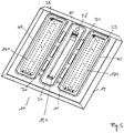
- the essential components of the lamp 1 according to the invention are a trough-shaped lamp housing 10 and a holding element 50 attached to the lamp housing 10, which encloses areas of the housing 10 with further covers 70, 80 in which electrical or electronic components of the lamp 1 are arranged.
- the luminaire 1 is divided into three areas, a central area running in the middle along a longitudinal direction, which serves to accommodate an operating device, and two light emission areas formed on both sides of the central area, in which the light sources and the optical components assigned to the light sources for the Light emission are arranged. The light is therefore emitted in the view according to FIG figure 1 over two essentially rectangular lateral areas of the lamp 1, over which light is emitted with high intensity.
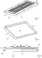
- the single in figure 3 The recognizable lamp housing 10 is trough-shaped with an approximately square housing base 11 in the illustrated embodiment, from which a laterally circumferential housing wall 12 extends downwards or in the light emission direction of the lamp 1, with the housing base 11 and housing wall 12 delimiting a lamp space.
- the housing 10 consists of a one-piece sheet metal part which has been stamped and shaped accordingly, with the side walls of the surrounding housing wall 12 preferably being realized simply by bending the edge regions of the sheet metal part accordingly and then optionally being connected to one another at the joints.
- the housing 10 shown in the figures can thus be produced in a particularly simple and cost-effective manner, since in particular no complex reshaping is required.
- the primary task of the flat housing base 11 is to enable the components of the lamp 1 responsible for generating and emitting light to be accommodated or supported over a wide area.
- three essentially flat areas are to be formed on the housing base 11 on its side facing the interior of the housing 10, a central flat area 20 and two lateral flat areas 25.
- the central area 20 is here for the later inclusion of an in figure 5 recognizable operating device 120 is provided, for example in the form of a converter.
- an in figure 5 recognizable operating device 120 is provided, for example in the form of a converter.
- it is essentially adapted to the width of the operating device 120 and, in the exemplary embodiment shown, is accordingly dimensioned somewhat narrower than the two lateral receiving regions 25.
- the two lateral receiving areas 25 each serve to store one or more LED circuit boards 130 (see also figure 5 ), each of which forms a large-area light source. All three receiving areas 20 and 25 are flat due to the special design of the lamp housing 10 in order to enable either the operating device 120 or the LED circuit boards 130 to be placed flat. This ensures efficient transfer of heat during the Allows operation on the housing base 11, whereby a dissipation of heat and thus cooling of the lamp components 120, 130 is improved.
- the operating device 120 and the LED circuit boards 130 are preferably fastened to the lamp housing 10 by means of screw connections, for which purpose corresponding openings or bores can then be provided in the housing 10, in particular in the housing base 11.
- the fastenings for the various electrical or electronic components are preferably designed in such a way that the lamp 1 is protected against the ingress of dust and/or moisture. Any screw connections that are used are therefore preferably designed to be sealed, so that the lamp 1 may meet corresponding requirements of a desired so-called IP protection class.
- the receiving areas 20 and 25 are preferably closed towards the back of the lamp housing 10 .
- An exception to this is the central receiving area 20, which also has a somewhat larger opening 26 on one end face, through which the passage of a power supply cable 125 for the power supply of the operating device 120 is made possible.
- appropriate sealing measures for example in the form of a grommet 140 or the like, are provided on the back of the housing 10, which allow the power supply cable 125 to be led out in a sealed manner, so that all three receiving areas 20 or 25 are as free as possible when the lamp 1 is installed are well sealed to the rear.
- control gear 120 and the LED light sources 130 are not arranged together in a single, tightly enclosed space, but rather that receiving spaces corresponding to the flat receiving areas 20 or 25 are formed, which are each closed in a sealed manner and accommodate either the converter 120 or the LED light sources 130 .
- the separate arrangement of these lamp components 120, 130 in the three separate rooms opens up the possibility of thermally decoupling the areas from one another on the one hand and on the other hand by appropriate design of the covers 70, 80 in a targeted manner making individual areas accessible for repair or maintenance measures, while other areas remain permanently closed.
- a further advantage of the separation is that the lamp housing 10 can be designed in such a way that cooling air can flow through in gaps between two adjacent receiving spaces.
- three elongated passage openings 30 are formed in the housing base 11 on both sides of the central receiving area 20, with the aid of which the cooling air ducts, which will be described in more detail later, are formed.
- These passage openings 30, which could of course also be designed differently in terms of their length and shape, if necessary, cause not only the flow of cooling air but also a reduction in material in the area between two adjacent receiving areas 20, 25. This has the consequence that between two adjacent areas there is a certain thermal decoupling and accordingly the risk is reduced that, for example, the heat generated by the LED illuminants 130 is transferred to the area 20 with the operating device 120 .
- each area 20, 25 is surrounded by its own ring-like seal 40, which interacts with a cover that will be described in more detail later.
- the figure 4 recognizable seals 40 are applied in a simple manner to the flat housing base 11 and thereby define the three receiving areas 20 and 25 respectively.
- the seals 40 can be applied to the base 11 in the form of a prefabricated sealing ring, for example glued on, or sprayed or foamed onto the housing base 11 in the desired configuration. It is crucial here that the housing base 11 itself does not have to have any special structures or other components in order to hold the seals 40 in the desired manner. Instead, these can be applied in a simple assembly step in such a way that the in figure 4 recognizable configuration results. This also contributes to simplifying the production of the lamp 1 overall.
- two approximately rectangular elongated holes 35 punched into the housing base 11 can be used, which extend transversely to the longitudinal direction of the receiving spaces 20, 25 between the adjacent seals 40. These openings 35 end just below the seals 30 so that they allow a cable to be fed through on the underside of the respective seal 40 without their sealing effect being significantly impaired.
- FIG. 2 Another possibility that in figure 2 is to use the openings 35 for the arrangement of a channel-forming component 36, which is attached to the housing 10 from the rear, for example snapped on.
- This component 36 has a tubular configuration and thereby forms a channel which extends at the rear of the housing 10 from the central receiving area 20 to an adjacent lateral receiving area 25 .
- the openings 35 are of appropriate length, the end area of the channel-forming component 36 opens into the bottom surface of the associated receiving area 20, 25, so that a channel-like or tube-like connection is achieved between the areas 20, 25, which in turn enables the protected laying of a corresponding allows electrical connection.
- the final sealing of the receiving areas 20, 25 for the operating device 120 and the LED lamps 130 is then carried out using the covers 70, 80.
- the housing 10 provides the three receiving areas 20 or 25 and the surrounding seals 40, but it is necessary That the areas are also closed according to the front side to protect the lighting components 120, 130 from external influences, especially from dust and / or moisture can.
- the retaining element 50 consists of a peripheral frame 51 which corresponds approximately to the shape of the lamp housing 10 and is therefore square in the present case, which has two connecting webs 52 running parallel to the longitudinal sides.
- the cover 80 is fastened to the holding element 50 using a plurality of screws which pass through the corresponding bores 53 or screw receptacles 83 in the webs 52 of the holding element 50 and the cover element 80 .
- the retaining element 50 is also fastened to the lamp housing 10 with the aid of a plurality of screws.
- the attachment of the cover 80 to the holding element 50 is designed in such a way that even when the holding element 50 is already installed on the lamp housing 10, only the cover for the central receiving area 20 can be opened and maintenance work can be carried out separately in this area, if necessary. or repair work can be carried out.
- the protected arrangement of the lighting means 130 which is described in more detail below, is then retained in this case, so that there is no risk of them being accidentally damaged or touched.
- the cover 80 has a dome-like or hood-like covering area 81 which is surrounded by a circumferential, flange-like web 82, with the already mentioned screw sockets 83 for the screw connection to the holding element 50 being formed on the two longitudinal sides of this web 82.
- the two frontal areas of the web 82 are received in corresponding recesses 54 on the underside of the retaining element 50, which are dimensioned such that when the cover element 80 is screwed on, the web 82 and the underside of the retaining element 50 lie flush in a common plane, like this in figure 9 can be seen, which shows the holding element 50 and the cover element 80 in the assembled state.
- a ring-like closed further web 85 extends from the outer circumference of the covering area 81 towards the back (and thus perpendicularly to the circumferential web 82 ), which forms a circumferentially closed sealing edge 86 .
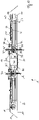
- the shape of the edge 86 is selected in such a way that when the retaining element 50 is mounted on the lamp housing 10 and the cover 80 attached thereto, the edge 86 touches the seal 40 or ideally dips into the flexible material of the seal 40, as is shown in figure 13 is indicated. As a result, a central receiving space A is enclosed in a completely sealed manner jointly by the housing 10 and the cover 80, so that the operating device 120 arranged therein is safely and reliably protected from external influences.
- the dome-like or hood-like cover 81 can protrude slightly compared to the level of the underside of the frame 51, so that it forms a somewhat recessed accommodation space A.
- the height and also the width of the cover 81 can be adapted to the dimensions of the operating device 120 and, if necessary, further electrical or electronic operating components for operating the lamp 1 as required.
- the retaining element 50 is fastened to the housing 10 via a large number of screw connections, with corresponding bores or openings in the housing base 11 of the lamp housing 10 being outside of the areas 20 or 25 to be sealed, so that the sealing of the receiving areas 20, 25 is not adversely affected.
- a sealing corresponding to the above-described interaction between the cover 80 and the seal 40 is also provided for the two receiving areas 25 for the LED illuminants 130 , with this function now being fulfilled by transparent covers 70 .
- These covers 70 are accommodated in the area of the openings 56 of the frame 51 formed on both sides of the hood-like cover 80, which ultimately form the light emission openings of the frame-like holding element 50, and are held and positioned by the holding element 50 in such a way that they are in turn connected to the seals 40 can work together.
- the housing 10 and the cover 70 then enclose a space B in which the LED lighting means 130 are accommodated.
- the Figures 10 to 12 show a conceivable embodiment for the cover 70, which also serves to influence the light emitted by the LEDs.
- the cover 70 has a flat light emission area 71, which is surrounded all around by a U-shaped edge 72, which has a limb 73 tapering out towards the seal 40, a connecting limb running transversely thereto and a connecting limb with the rest of the Cover 70 has connecting inner leg, the U-shape on the one hand increases the stability of the cover 70 and on the other hand the outer leg 73 is directed upwards and forms a circumferential sealing edge 74 in one plane.
- the function of this sealing edge 74 is comparable to edge 86 of cover 80.
- edge 74 dips into surrounding seal 40 on housing base 11 of light housing 10 and thereby completely encloses corresponding receiving area 25 for LED light sources 130 In this case, too, a completely sealed, enclosed space is obtained, in which the LED lighting means 130 are now accommodated.
- the holding or positioning of the cover 70 required for this is realized by the holding element 50 which, surrounding the two openings 56, has a bearing edge 57 or a bearing web which projects inwards. As per the sectional view figure 13 can be removed, the covers 70 then lie with their lower edge of the U-shaped edge 72 floating on the support edge 57, with the dimensions of the retaining element 50 being selected in such a way that it is ensured that the cover 70 actually forms a seal with the respective seal 40 works together.
- the bearing edge 57 extends in a plane transversely or orthogonally to a pressing direction for pressing the cover 70 into contact with the seal 40.
- support or bearing areas formed in sections could also be provided, which are then distributed, are preferably evenly distributed around the circumference of the openings 56 are arranged.
- the cover 70 is therefore not rigidly connected to the holding element 50 or the lamp housing 10 . Instead, during assembly of the lamp 1, only the cover 70 is inserted accordingly into the holding element 50 and this is then screwed to the lamp housing 10 in the manner described above.
- the cover 70 also has suitable optical elements for influencing the light emitted by the LED illuminants 130 .
- TIR lenses 75 positioned on the rear side opposite the light-emitting surface of the cover 70, which in a known manner focus the light emitted by an LED and emit it in a directed manner toward the underside.
- one lens 75 is used for each LED or LED cluster of the lighting means 130 , the LED or the associated LED cluster then engaging in a recess formed on the upper side of the lens 75 .
- This arrangement of the lens 75 with respect to the associated LED and the design of the lens 75 ensures that the LEDs in almost all Directions emitted light is influenced in the desired way and used for efficient light emission.
- the lenses 75 are an integral part of the cover 70 and are formed integrally on the rear side in a corresponding manner.
- the cover 70 is preferably made of the same light-permeable material throughout, although it would still be conceivable for those components through which the light passes or which are intended to influence the light to be made of a different material than the rest of the cover 70
- the covers 70 can have optical materials such as scattering particles or conversion particles, optical structures such as a roughened surface, and/or optical elements such as lenses or a lens array.
- cover 70 in such a way that it is an integral part of the holding element 50 .
- the cover 80 for the operating device 120 could also be designed as an integral part of the holding element 50 .
- a further function of the holding element 50 with the cover 80 fastened thereto is that they allow cooling air to flow through the passage openings 30 of the lamp housing 10 .
- the holding element 50 and the cover 80 have openings 58 , 88 corresponding to the through-openings 30 of the housing 10 , the openings 88 of the cover 80 being surrounded by circumferential webs 89 in each case.
- These webs 89 are oriented essentially transversely to the plane of the openings, but in this case are aligned slightly inclined and are aligned on their upper side with the through openings 30 of the luminaire housing 10, so that cooling air ducts are formed which widen slightly downwards and which, as already mentioned, are on both sides of the Recording areas 20, 25 for the LED lamps 130 and for the operating device 120 are formed and according to the arrows of the illustration figure 13 allow air to flow upwards.
- the holding element 50 is preferably designed as a one-piece plastic part and is produced here in particular as part of an injection molding process. Depending on whether the covers 70 or 80 are to be an integral part of the holding element 50, a two-component injection molding process can then also be used if necessary. In this case, the use of a chemically resistant material is preferably provided at least for the cover 80 in order to be able to protect the lamp components arranged in the space A as well as possible. Furthermore, it would also be conceivable to design the holding element 50 in several parts, but this leads to an increase in the number of components and is therefore less preferred.
- the solution according to the invention opens up the possibility of realizing a lamp which, in terms of its photometric properties, is similar to the lamps known from the prior art and likewise enables the various electrical or electronic components to be accommodated in a protected manner. Efficient dissipation of the heat generated during operation is also guaranteed. All of these properties are achieved with the aid of the housing designed according to the invention, which, however, can be manufactured in a much simpler and more cost-effective manner than previously known housings, since only a correspondingly stamped and bent sheet metal part is used here.
- the lamp housing 210 as a whole is essentially comparable to that of the lamp in FIG WO 2020/228993 A1 ,
- a trough-like configuration with a housing base 211 and a laterally surrounding housing wall 212 is provided and the housing 210 provides three receiving areas 20, 25 for receiving light sources 130 and an operating device 130.
- the lamp housing 210 is modular.
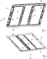
- the housing 210 is formed from three trough-shaped partial lamp housings 210a, 210b and 210c, each partial lamp housing 210a, 210b, 210c corresponding to one of the receiving areas 20, 25 of the lamp.
- These sub-housings 210a, 210b and 210c are arranged next to one another and joined together as described below, so that ultimately the lamp housing 210, which is essentially square in design overall, results.
- the housing 10 of Figures 1 to 13 This then in turn has the properties of the housing 10 of Figures 1 to 13 on and is intended to be used with the above Holding element 50 and the covers 70, 80 to cooperate in an analogous manner.
- the receiving areas 20, 25 are each surrounded by a ring-like seal 40, which is contacted by the sealing edges 74 and 86 of the covers 70 and 80 in order to enclose the resulting receiving spaces A, B accordingly.
- openings 30 are also provided in the housing 210 between two adjacent receiving areas 20, 25, through which cooling air channels are formed.
- two adjacent lamp housing sections 210a, 210b and 210c are connected via connecting elements 220, which are formed by U-shaped or O-shaped angle elements which each extend between two lamp section housings 210a, 210b and 210c.
- These connecting elements 220 can, for example, then allow the corresponding adjacent lamp housing part 210a, 210b, 210c to be fastened, for example via corresponding screw connections, which then interact with the facing side walls of the corresponding lamp part housing 210a, 210b, 210c.
- the through-openings 30 which are also present and which enable the cooling air to flow through and on the other hand enable thermal decoupling of the adjacent receiving regions 20 , 25 , are formed in the connecting elements 220 .
- the respective partial lamp housings 210a, 210b, 210c are therefore of very simple design with a closed bottom area and peripheral side walls. However, structures that are difficult to produce in other ways are not required. Only the connecting elements 80 represent a possibly somewhat more complex shape, which can be produced with a certain amount of effort.
- the lamp part housing 210a, 210b, 210c can be formed again in a very simple manner by simple sheet metal parts, as is the case with the lamp housing Figures 1 to 13 the case is.
- the interconnected housing walls of the partial lamp housings 210a, 210b, 210c can have cable openings 215, e.g. bores, via which the interconnected partial lamp housings 210a, 210b, 210c can be electrically connected to one another, for example again via a channel-forming component which is attached to the cable openings 215 is arranged.
- the cable openings 215 can be sealed.
- An advantage of the modular design of the housing is that, if necessary, different light housing parts can be used. If, for example, the central receiving area for the control gear is to be enlarged in order to accommodate additional emergency power supply means in the form of batteries or the like, a variant of the central lighting part housing that is correspondingly larger could be used for this purpose. On the other hand, the two side lamp housings for accommodating the lamps could continue to be used in an unchanged form. Ultimately, a modular system could be made available in this way, from which a wide variety of choices can be made in order ultimately to realize a desired luminaire. Despite everything, all the different variants can be produced in a simple and inexpensive manner.
- the solutions according to the invention create the possibility of realizing a lamp which, as desired, is able to generate and emit light with high intensity, although the associated material and assembly costs are further reduced compared to previously known solutions becomes.
Landscapes
- Engineering & Computer Science (AREA)
- General Engineering & Computer Science (AREA)
- Microelectronics & Electronic Packaging (AREA)
- Arrangement Of Elements, Cooling, Sealing, Or The Like Of Lighting Devices (AREA)
Applications Claiming Priority (2)
| Application Number | Priority Date | Filing Date | Title |
|---|---|---|---|
| ATGM50226/2020U AT17531U1 (de) | 2020-11-19 | 2020-11-19 | Modulare Leuchte |
| DE102021102586.9A DE102021102586A1 (de) | 2020-11-19 | 2021-02-04 | Leuchte mit darin aufgenommenen Leuchtenkomponenten |
Publications (2)
| Publication Number | Publication Date |
|---|---|
| EP4001739A1 true EP4001739A1 (fr) | 2022-05-25 |
| EP4001739B1 EP4001739B1 (fr) | 2024-01-03 |
Family
ID=81214573
Family Applications (1)
| Application Number | Title | Priority Date | Filing Date |
|---|---|---|---|
| EP21208673.0A Active EP4001739B1 (fr) | 2020-11-19 | 2021-11-17 | Luminaire pourvu de composants de luminaire intégrés |
Country Status (1)
| Country | Link |
|---|---|
| EP (1) | EP4001739B1 (fr) |
Citations (8)
| Publication number | Priority date | Publication date | Assignee | Title |
|---|---|---|---|---|
| US20110188233A1 (en) * | 2008-09-15 | 2011-08-04 | Led Roadway Lighting Ltd. | Light emitting diode (led) roadway lighting fixture |
| US8042977B1 (en) * | 2008-05-05 | 2011-10-25 | Koninklijke Philips Electronics N.V. | Troffer luminaire |
| DE102011081369A1 (de) * | 2011-08-23 | 2013-02-28 | Trilux Gmbh & Co. Kg | Leuchte, insbesondere LED-Leuchte mit passiver Kühlung |
| WO2014086770A1 (fr) | 2012-12-04 | 2014-06-12 | Zumtobel Lighting Gmbh | Appareil d'éclairage pourvu de surfaces de guidage d'air |
| US20160208998A1 (en) * | 2013-08-26 | 2016-07-21 | Delta T Corporation | Tunable luminaire and related methods to control light output |
| WO2020228996A1 (fr) | 2019-05-15 | 2020-11-19 | Zumtobel Lighting Gmbh | Appareil d'éclairage comportant des moyens d'éclairage logés de manière protégée |
| WO2020228997A1 (fr) | 2019-05-16 | 2020-11-19 | Ab Sandvik Coromant | Outil rotatif pour coupe de métaux |
| WO2020228993A1 (fr) | 2019-05-15 | 2020-11-19 | Zumtobel Lighting Gmbh | Logement d'appareil d'éclairage en forme de cuve |
Family Cites Families (2)
| Publication number | Priority date | Publication date | Assignee | Title |
|---|---|---|---|---|
| DE202014102002U1 (de) * | 2014-04-29 | 2015-07-31 | Zumtobel Lighting Gmbh | Dichtung |
| US10054285B2 (en) * | 2016-06-24 | 2018-08-21 | Cree, Inc. | Light fixture and optic with light-transmissive shield |
-
2021
- 2021-11-17 EP EP21208673.0A patent/EP4001739B1/fr active Active
Patent Citations (8)
| Publication number | Priority date | Publication date | Assignee | Title |
|---|---|---|---|---|
| US8042977B1 (en) * | 2008-05-05 | 2011-10-25 | Koninklijke Philips Electronics N.V. | Troffer luminaire |
| US20110188233A1 (en) * | 2008-09-15 | 2011-08-04 | Led Roadway Lighting Ltd. | Light emitting diode (led) roadway lighting fixture |
| DE102011081369A1 (de) * | 2011-08-23 | 2013-02-28 | Trilux Gmbh & Co. Kg | Leuchte, insbesondere LED-Leuchte mit passiver Kühlung |
| WO2014086770A1 (fr) | 2012-12-04 | 2014-06-12 | Zumtobel Lighting Gmbh | Appareil d'éclairage pourvu de surfaces de guidage d'air |
| US20160208998A1 (en) * | 2013-08-26 | 2016-07-21 | Delta T Corporation | Tunable luminaire and related methods to control light output |
| WO2020228996A1 (fr) | 2019-05-15 | 2020-11-19 | Zumtobel Lighting Gmbh | Appareil d'éclairage comportant des moyens d'éclairage logés de manière protégée |
| WO2020228993A1 (fr) | 2019-05-15 | 2020-11-19 | Zumtobel Lighting Gmbh | Logement d'appareil d'éclairage en forme de cuve |
| WO2020228997A1 (fr) | 2019-05-16 | 2020-11-19 | Ab Sandvik Coromant | Outil rotatif pour coupe de métaux |
Also Published As
| Publication number | Publication date |
|---|---|
| EP4001739B1 (fr) | 2024-01-03 |
Similar Documents
| Publication | Publication Date | Title |
|---|---|---|
| EP3969806B1 (fr) | Appareil d'éclairage comportant des moyens d'éclairage logés de manière protégée | |
| AT17709U1 (de) | Wannenförmiges Leuchtengehäuse | |
| EP3969804B1 (fr) | Logement d'appareil d'éclairage en forme de cuve | |
| DE202011107787U1 (de) | Lichtemissionsvorrichtung | |
| EP3366991B1 (fr) | Support d'appareil pour luminaire | |
| EP2177823B1 (fr) | Module d'intégration à DEL, agencement d'éclairage et construction de plafond ou de mur à l'aide de ce module d'intégration à DEL | |
| DE102020101152B4 (de) | Verfahren und Bausatz zum Bilden einer Leuchte | |
| EP4001739B1 (fr) | Luminaire pourvu de composants de luminaire intégrés | |
| DE102021102586A1 (de) | Leuchte mit darin aufgenommenen Leuchtenkomponenten | |
| AT17710U1 (de) | Wannenförmiges Leuchtengehäuse | |
| DE102015222187A1 (de) | Wannenleuchte | |
| EP3969807B1 (fr) | Appareil d'éclairage comportant des canaux à air de refroidissement | |
| EP4040038A1 (fr) | Luminaire pourvu de composants de luminaire protégés | |
| DE102023111028A1 (de) | Modulare leuchte | |
| EP3969805A1 (fr) | Appareil d'éclairage comportant un composant d'appareil d'éclairage logé de manière protégée | |
| DE102021102554A1 (de) | Leuchtengehäuse zur aufnahme einer leuchtenkomponente | |
| WO2025131821A1 (fr) | Kit de luminaire et luminaire modulaire | |
| DE202024101912U1 (de) | Miniaturisierte Leuchte | |
| DE102025143023A1 (de) | Gehäuse für eine Leuchte | |
| EP2833050B1 (fr) | Lampe suspendue dotée d'une source lumineuse destinée à produire un éclairage indirect |
Legal Events
| Date | Code | Title | Description |
|---|---|---|---|
| PUAI | Public reference made under article 153(3) epc to a published international application that has entered the european phase |
Free format text: ORIGINAL CODE: 0009012 |
|
| STAA | Information on the status of an ep patent application or granted ep patent |
Free format text: STATUS: THE APPLICATION HAS BEEN PUBLISHED |
|
| AK | Designated contracting states |
Kind code of ref document: A1 Designated state(s): AL AT BE BG CH CY CZ DE DK EE ES FI FR GB GR HR HU IE IS IT LI LT LU LV MC MK MT NL NO PL PT RO RS SE SI SK SM TR |
|
| STAA | Information on the status of an ep patent application or granted ep patent |
Free format text: STATUS: REQUEST FOR EXAMINATION WAS MADE |
|
| 17P | Request for examination filed |
Effective date: 20220531 |
|
| RBV | Designated contracting states (corrected) |
Designated state(s): AL AT BE BG CH CY CZ DE DK EE ES FI FR GB GR HR HU IE IS IT LI LT LU LV MC MK MT NL NO PL PT RO RS SE SI SK SM TR |
|
| RIC1 | Information provided on ipc code assigned before grant |
Ipc: F21Y 115/10 20160101ALN20230719BHEP Ipc: F21Y 105/10 20160101ALN20230719BHEP Ipc: F21W 131/40 20060101ALN20230719BHEP Ipc: F21V 29/83 20150101ALN20230719BHEP Ipc: F21V 23/02 20060101ALN20230719BHEP Ipc: F21V 17/12 20060101ALN20230719BHEP Ipc: F21V 5/00 20180101ALN20230719BHEP Ipc: F21V 31/00 20060101ALI20230719BHEP Ipc: F21V 23/00 20150101ALI20230719BHEP Ipc: F21V 15/01 20060101ALI20230719BHEP Ipc: F21S 8/06 20060101ALI20230719BHEP Ipc: F21S 8/04 20060101AFI20230719BHEP |
|
| GRAP | Despatch of communication of intention to grant a patent |
Free format text: ORIGINAL CODE: EPIDOSNIGR1 |
|
| STAA | Information on the status of an ep patent application or granted ep patent |
Free format text: STATUS: GRANT OF PATENT IS INTENDED |
|
| RIC1 | Information provided on ipc code assigned before grant |
Ipc: F21Y 115/10 20160101ALN20230906BHEP Ipc: F21Y 105/10 20160101ALN20230906BHEP Ipc: F21W 131/40 20060101ALN20230906BHEP Ipc: F21V 29/83 20150101ALN20230906BHEP Ipc: F21V 23/02 20060101ALN20230906BHEP Ipc: F21V 17/12 20060101ALN20230906BHEP Ipc: F21V 5/00 20180101ALN20230906BHEP Ipc: F21V 31/00 20060101ALI20230906BHEP Ipc: F21V 23/00 20150101ALI20230906BHEP Ipc: F21V 15/01 20060101ALI20230906BHEP Ipc: F21S 8/06 20060101ALI20230906BHEP Ipc: F21S 8/04 20060101AFI20230906BHEP |
|
| INTG | Intention to grant announced |
Effective date: 20230922 |
|
| RIC1 | Information provided on ipc code assigned before grant |
Ipc: F21Y 115/10 20160101ALN20230914BHEP Ipc: F21Y 105/10 20160101ALN20230914BHEP Ipc: F21W 131/40 20060101ALN20230914BHEP Ipc: F21V 29/83 20150101ALN20230914BHEP Ipc: F21V 23/02 20060101ALN20230914BHEP Ipc: F21V 17/12 20060101ALN20230914BHEP Ipc: F21V 5/00 20180101ALN20230914BHEP Ipc: F21V 31/00 20060101ALI20230914BHEP Ipc: F21V 23/00 20150101ALI20230914BHEP Ipc: F21V 15/01 20060101ALI20230914BHEP Ipc: F21S 8/06 20060101ALI20230914BHEP Ipc: F21S 8/04 20060101AFI20230914BHEP |
|
| GRAS | Grant fee paid |
Free format text: ORIGINAL CODE: EPIDOSNIGR3 |
|
| GRAA | (expected) grant |
Free format text: ORIGINAL CODE: 0009210 |
|
| STAA | Information on the status of an ep patent application or granted ep patent |
Free format text: STATUS: THE PATENT HAS BEEN GRANTED |
|
| AK | Designated contracting states |
Kind code of ref document: B1 Designated state(s): AL AT BE BG CH CY CZ DE DK EE ES FI FR GB GR HR HU IE IS IT LI LT LU LV MC MK MT NL NO PL PT RO RS SE SI SK SM TR |
|
| REG | Reference to a national code |
Ref country code: GB Ref legal event code: FG4D Free format text: NOT ENGLISH |
|
| P01 | Opt-out of the competence of the unified patent court (upc) registered |
Effective date: 20231130 |
|
| REG | Reference to a national code |
Ref country code: DE Ref legal event code: R096 Ref document number: 502021002349 Country of ref document: DE |
|
| REG | Reference to a national code |
Ref country code: CH Ref legal event code: EP |
|
| REG | Reference to a national code |
Ref country code: IE Ref legal event code: FG4D Free format text: LANGUAGE OF EP DOCUMENT: GERMAN |
|
| REG | Reference to a national code |
Ref country code: LT Ref legal event code: MG9D |
|
| PG25 | Lapsed in a contracting state [announced via postgrant information from national office to epo] |
Ref country code: ES Free format text: LAPSE BECAUSE OF FAILURE TO SUBMIT A TRANSLATION OF THE DESCRIPTION OR TO PAY THE FEE WITHIN THE PRESCRIBED TIME-LIMIT Effective date: 20240103 |
|
| PG25 | Lapsed in a contracting state [announced via postgrant information from national office to epo] |
Ref country code: ES Free format text: LAPSE BECAUSE OF FAILURE TO SUBMIT A TRANSLATION OF THE DESCRIPTION OR TO PAY THE FEE WITHIN THE PRESCRIBED TIME-LIMIT Effective date: 20240103 |
|
| REG | Reference to a national code |
Ref country code: NL Ref legal event code: MP Effective date: 20240103 |
|
| PG25 | Lapsed in a contracting state [announced via postgrant information from national office to epo] |
Ref country code: NL Free format text: LAPSE BECAUSE OF FAILURE TO SUBMIT A TRANSLATION OF THE DESCRIPTION OR TO PAY THE FEE WITHIN THE PRESCRIBED TIME-LIMIT Effective date: 20240103 |
|
| PG25 | Lapsed in a contracting state [announced via postgrant information from national office to epo] |
Ref country code: NL Free format text: LAPSE BECAUSE OF FAILURE TO SUBMIT A TRANSLATION OF THE DESCRIPTION OR TO PAY THE FEE WITHIN THE PRESCRIBED TIME-LIMIT Effective date: 20240103 |
|
| PG25 | Lapsed in a contracting state [announced via postgrant information from national office to epo] |
Ref country code: IS Free format text: LAPSE BECAUSE OF FAILURE TO SUBMIT A TRANSLATION OF THE DESCRIPTION OR TO PAY THE FEE WITHIN THE PRESCRIBED TIME-LIMIT Effective date: 20240503 |
|
| PG25 | Lapsed in a contracting state [announced via postgrant information from national office to epo] |
Ref country code: LT Free format text: LAPSE BECAUSE OF FAILURE TO SUBMIT A TRANSLATION OF THE DESCRIPTION OR TO PAY THE FEE WITHIN THE PRESCRIBED TIME-LIMIT Effective date: 20240103 |
|
| PG25 | Lapsed in a contracting state [announced via postgrant information from national office to epo] |
Ref country code: GR Free format text: LAPSE BECAUSE OF FAILURE TO SUBMIT A TRANSLATION OF THE DESCRIPTION OR TO PAY THE FEE WITHIN THE PRESCRIBED TIME-LIMIT Effective date: 20240404 |
|
| PG25 | Lapsed in a contracting state [announced via postgrant information from national office to epo] |
Ref country code: HR Free format text: LAPSE BECAUSE OF FAILURE TO SUBMIT A TRANSLATION OF THE DESCRIPTION OR TO PAY THE FEE WITHIN THE PRESCRIBED TIME-LIMIT Effective date: 20240103 Ref country code: RS Free format text: LAPSE BECAUSE OF FAILURE TO SUBMIT A TRANSLATION OF THE DESCRIPTION OR TO PAY THE FEE WITHIN THE PRESCRIBED TIME-LIMIT Effective date: 20240403 |
|
| PG25 | Lapsed in a contracting state [announced via postgrant information from national office to epo] |
Ref country code: CZ Free format text: LAPSE BECAUSE OF FAILURE TO SUBMIT A TRANSLATION OF THE DESCRIPTION OR TO PAY THE FEE WITHIN THE PRESCRIBED TIME-LIMIT Effective date: 20240103 |
|
| PG25 | Lapsed in a contracting state [announced via postgrant information from national office to epo] |
Ref country code: RS Free format text: LAPSE BECAUSE OF FAILURE TO SUBMIT A TRANSLATION OF THE DESCRIPTION OR TO PAY THE FEE WITHIN THE PRESCRIBED TIME-LIMIT Effective date: 20240403 Ref country code: NO Free format text: LAPSE BECAUSE OF FAILURE TO SUBMIT A TRANSLATION OF THE DESCRIPTION OR TO PAY THE FEE WITHIN THE PRESCRIBED TIME-LIMIT Effective date: 20240403 Ref country code: LT Free format text: LAPSE BECAUSE OF FAILURE TO SUBMIT A TRANSLATION OF THE DESCRIPTION OR TO PAY THE FEE WITHIN THE PRESCRIBED TIME-LIMIT Effective date: 20240103 Ref country code: IS Free format text: LAPSE BECAUSE OF FAILURE TO SUBMIT A TRANSLATION OF THE DESCRIPTION OR TO PAY THE FEE WITHIN THE PRESCRIBED TIME-LIMIT Effective date: 20240503 Ref country code: HR Free format text: LAPSE BECAUSE OF FAILURE TO SUBMIT A TRANSLATION OF THE DESCRIPTION OR TO PAY THE FEE WITHIN THE PRESCRIBED TIME-LIMIT Effective date: 20240103 Ref country code: GR Free format text: LAPSE BECAUSE OF FAILURE TO SUBMIT A TRANSLATION OF THE DESCRIPTION OR TO PAY THE FEE WITHIN THE PRESCRIBED TIME-LIMIT Effective date: 20240404 Ref country code: CZ Free format text: LAPSE BECAUSE OF FAILURE TO SUBMIT A TRANSLATION OF THE DESCRIPTION OR TO PAY THE FEE WITHIN THE PRESCRIBED TIME-LIMIT Effective date: 20240103 Ref country code: BG Free format text: LAPSE BECAUSE OF FAILURE TO SUBMIT A TRANSLATION OF THE DESCRIPTION OR TO PAY THE FEE WITHIN THE PRESCRIBED TIME-LIMIT Effective date: 20240103 |
|
| PG25 | Lapsed in a contracting state [announced via postgrant information from national office to epo] |
Ref country code: PT Free format text: LAPSE BECAUSE OF FAILURE TO SUBMIT A TRANSLATION OF THE DESCRIPTION OR TO PAY THE FEE WITHIN THE PRESCRIBED TIME-LIMIT Effective date: 20240503 Ref country code: PL Free format text: LAPSE BECAUSE OF FAILURE TO SUBMIT A TRANSLATION OF THE DESCRIPTION OR TO PAY THE FEE WITHIN THE PRESCRIBED TIME-LIMIT Effective date: 20240103 |
|
| PG25 | Lapsed in a contracting state [announced via postgrant information from national office to epo] |
Ref country code: SE Free format text: LAPSE BECAUSE OF FAILURE TO SUBMIT A TRANSLATION OF THE DESCRIPTION OR TO PAY THE FEE WITHIN THE PRESCRIBED TIME-LIMIT Effective date: 20240103 Ref country code: PT Free format text: LAPSE BECAUSE OF FAILURE TO SUBMIT A TRANSLATION OF THE DESCRIPTION OR TO PAY THE FEE WITHIN THE PRESCRIBED TIME-LIMIT Effective date: 20240503 Ref country code: PL Free format text: LAPSE BECAUSE OF FAILURE TO SUBMIT A TRANSLATION OF THE DESCRIPTION OR TO PAY THE FEE WITHIN THE PRESCRIBED TIME-LIMIT Effective date: 20240103 Ref country code: LV Free format text: LAPSE BECAUSE OF FAILURE TO SUBMIT A TRANSLATION OF THE DESCRIPTION OR TO PAY THE FEE WITHIN THE PRESCRIBED TIME-LIMIT Effective date: 20240103 |
|
| REG | Reference to a national code |
Ref country code: DE Ref legal event code: R097 Ref document number: 502021002349 Country of ref document: DE |
|
| PG25 | Lapsed in a contracting state [announced via postgrant information from national office to epo] |
Ref country code: DK Free format text: LAPSE BECAUSE OF FAILURE TO SUBMIT A TRANSLATION OF THE DESCRIPTION OR TO PAY THE FEE WITHIN THE PRESCRIBED TIME-LIMIT Effective date: 20240103 |
|
| PG25 | Lapsed in a contracting state [announced via postgrant information from national office to epo] |
Ref country code: SM Free format text: LAPSE BECAUSE OF FAILURE TO SUBMIT A TRANSLATION OF THE DESCRIPTION OR TO PAY THE FEE WITHIN THE PRESCRIBED TIME-LIMIT Effective date: 20240103 |
|
| PG25 | Lapsed in a contracting state [announced via postgrant information from national office to epo] |
Ref country code: EE Free format text: LAPSE BECAUSE OF FAILURE TO SUBMIT A TRANSLATION OF THE DESCRIPTION OR TO PAY THE FEE WITHIN THE PRESCRIBED TIME-LIMIT Effective date: 20240103 |
|
| PG25 | Lapsed in a contracting state [announced via postgrant information from national office to epo] |
Ref country code: SK Free format text: LAPSE BECAUSE OF FAILURE TO SUBMIT A TRANSLATION OF THE DESCRIPTION OR TO PAY THE FEE WITHIN THE PRESCRIBED TIME-LIMIT Effective date: 20240103 |
|
| PG25 | Lapsed in a contracting state [announced via postgrant information from national office to epo] |
Ref country code: SM Free format text: LAPSE BECAUSE OF FAILURE TO SUBMIT A TRANSLATION OF THE DESCRIPTION OR TO PAY THE FEE WITHIN THE PRESCRIBED TIME-LIMIT Effective date: 20240103 Ref country code: SK Free format text: LAPSE BECAUSE OF FAILURE TO SUBMIT A TRANSLATION OF THE DESCRIPTION OR TO PAY THE FEE WITHIN THE PRESCRIBED TIME-LIMIT Effective date: 20240103 Ref country code: RO Free format text: LAPSE BECAUSE OF FAILURE TO SUBMIT A TRANSLATION OF THE DESCRIPTION OR TO PAY THE FEE WITHIN THE PRESCRIBED TIME-LIMIT Effective date: 20240103 Ref country code: EE Free format text: LAPSE BECAUSE OF FAILURE TO SUBMIT A TRANSLATION OF THE DESCRIPTION OR TO PAY THE FEE WITHIN THE PRESCRIBED TIME-LIMIT Effective date: 20240103 Ref country code: DK Free format text: LAPSE BECAUSE OF FAILURE TO SUBMIT A TRANSLATION OF THE DESCRIPTION OR TO PAY THE FEE WITHIN THE PRESCRIBED TIME-LIMIT Effective date: 20240103 |
|
| PLBE | No opposition filed within time limit |
Free format text: ORIGINAL CODE: 0009261 |
|
| STAA | Information on the status of an ep patent application or granted ep patent |
Free format text: STATUS: NO OPPOSITION FILED WITHIN TIME LIMIT |
|
| PG25 | Lapsed in a contracting state [announced via postgrant information from national office to epo] |
Ref country code: IT Free format text: LAPSE BECAUSE OF FAILURE TO SUBMIT A TRANSLATION OF THE DESCRIPTION OR TO PAY THE FEE WITHIN THE PRESCRIBED TIME-LIMIT Effective date: 20240103 |
|
| 26N | No opposition filed |
Effective date: 20241007 |
|
| PG25 | Lapsed in a contracting state [announced via postgrant information from national office to epo] |
Ref country code: IT Free format text: LAPSE BECAUSE OF FAILURE TO SUBMIT A TRANSLATION OF THE DESCRIPTION OR TO PAY THE FEE WITHIN THE PRESCRIBED TIME-LIMIT Effective date: 20240103 |
|
| PG25 | Lapsed in a contracting state [announced via postgrant information from national office to epo] |
Ref country code: SI Free format text: LAPSE BECAUSE OF FAILURE TO SUBMIT A TRANSLATION OF THE DESCRIPTION OR TO PAY THE FEE WITHIN THE PRESCRIBED TIME-LIMIT Effective date: 20240103 |
|
| PG25 | Lapsed in a contracting state [announced via postgrant information from national office to epo] |
Ref country code: MC Free format text: LAPSE BECAUSE OF FAILURE TO SUBMIT A TRANSLATION OF THE DESCRIPTION OR TO PAY THE FEE WITHIN THE PRESCRIBED TIME-LIMIT Effective date: 20240103 |
|
| PG25 | Lapsed in a contracting state [announced via postgrant information from national office to epo] |
Ref country code: LU Free format text: LAPSE BECAUSE OF NON-PAYMENT OF DUE FEES Effective date: 20241117 |
|
| REG | Reference to a national code |
Ref country code: BE Ref legal event code: MM Effective date: 20241130 |
|
| PG25 | Lapsed in a contracting state [announced via postgrant information from national office to epo] |
Ref country code: FI Free format text: LAPSE BECAUSE OF FAILURE TO SUBMIT A TRANSLATION OF THE DESCRIPTION OR TO PAY THE FEE WITHIN THE PRESCRIBED TIME-LIMIT Effective date: 20240103 |
|
| PG25 | Lapsed in a contracting state [announced via postgrant information from national office to epo] |
Ref country code: BE Free format text: LAPSE BECAUSE OF NON-PAYMENT OF DUE FEES Effective date: 20241130 |
|
| PG25 | Lapsed in a contracting state [announced via postgrant information from national office to epo] |
Ref country code: IE Free format text: LAPSE BECAUSE OF NON-PAYMENT OF DUE FEES Effective date: 20241117 |
|
| REG | Reference to a national code |
Ref country code: CH Ref legal event code: U11 Free format text: ST27 STATUS EVENT CODE: U-0-0-U10-U11 (AS PROVIDED BY THE NATIONAL OFFICE) Effective date: 20251201 |
|
| PGFP | Annual fee paid to national office [announced via postgrant information from national office to epo] |
Ref country code: DE Payment date: 20251126 Year of fee payment: 5 |
|
| PGFP | Annual fee paid to national office [announced via postgrant information from national office to epo] |
Ref country code: GB Payment date: 20251125 Year of fee payment: 5 |
|
| PGFP | Annual fee paid to national office [announced via postgrant information from national office to epo] |
Ref country code: AT Payment date: 20260113 Year of fee payment: 5 |
|
| PGFP | Annual fee paid to national office [announced via postgrant information from national office to epo] |
Ref country code: FR Payment date: 20251124 Year of fee payment: 5 |
|
| PGFP | Annual fee paid to national office [announced via postgrant information from national office to epo] |
Ref country code: CH Payment date: 20251201 Year of fee payment: 5 |
|
| PG25 | Lapsed in a contracting state [announced via postgrant information from national office to epo] |
Ref country code: HU Free format text: LAPSE BECAUSE OF FAILURE TO SUBMIT A TRANSLATION OF THE DESCRIPTION OR TO PAY THE FEE WITHIN THE PRESCRIBED TIME-LIMIT; INVALID AB INITIO Effective date: 20211117 |
|
| PG25 | Lapsed in a contracting state [announced via postgrant information from national office to epo] |
Ref country code: CY Free format text: LAPSE BECAUSE OF FAILURE TO SUBMIT A TRANSLATION OF THE DESCRIPTION OR TO PAY THE FEE WITHIN THE PRESCRIBED TIME-LIMIT; INVALID AB INITIO Effective date: 20211117 |