EP4001909A1 - Wasserqualitätsmesssystem - Google Patents
Wasserqualitätsmesssystem Download PDFInfo
- Publication number
- EP4001909A1 EP4001909A1 EP20841118.1A EP20841118A EP4001909A1 EP 4001909 A1 EP4001909 A1 EP 4001909A1 EP 20841118 A EP20841118 A EP 20841118A EP 4001909 A1 EP4001909 A1 EP 4001909A1
- Authority
- EP
- European Patent Office
- Prior art keywords
- section
- rearing
- water
- rearing water
- sensor
- Prior art date
- Legal status (The legal status is an assumption and is not a legal conclusion. Google has not performed a legal analysis and makes no representation as to the accuracy of the status listed.)
- Withdrawn
Links
Images




Classifications
-
- G—PHYSICS
- G01—MEASURING; TESTING
- G01N—INVESTIGATING OR ANALYSING MATERIALS BY DETERMINING THEIR CHEMICAL OR PHYSICAL PROPERTIES
- G01N27/00—Investigating or analysing materials by the use of electric, electrochemical, or magnetic means
- G01N27/26—Investigating or analysing materials by the use of electric, electrochemical, or magnetic means by investigating electrochemical variables; by using electrolysis or electrophoresis
- G01N27/403—Cells and electrode assemblies
- G01N27/406—Cells and probes with solid electrolytes
-
- G—PHYSICS
- G01—MEASURING; TESTING
- G01N—INVESTIGATING OR ANALYSING MATERIALS BY DETERMINING THEIR CHEMICAL OR PHYSICAL PROPERTIES
- G01N27/00—Investigating or analysing materials by the use of electric, electrochemical, or magnetic means
- G01N27/26—Investigating or analysing materials by the use of electric, electrochemical, or magnetic means by investigating electrochemical variables; by using electrolysis or electrophoresis
- G01N27/28—Electrolytic cell components
- G01N27/30—Electrodes, e.g. test electrodes; Half-cells
- G01N27/333—Ion-selective electrodes or membranes
-
- A—HUMAN NECESSITIES
- A01—AGRICULTURE; FORESTRY; ANIMAL HUSBANDRY; HUNTING; TRAPPING; FISHING
- A01K—ANIMAL HUSBANDRY; AVICULTURE; APICULTURE; PISCICULTURE; FISHING; REARING OR BREEDING ANIMALS, NOT OTHERWISE PROVIDED FOR; NEW BREEDS OF ANIMALS
- A01K63/00—Receptacles for live fish, e.g. aquaria; Terraria
- A01K63/04—Arrangements for treating water specially adapted to receptacles for live fish
- A01K63/045—Filters for aquaria
-
- C—CHEMISTRY; METALLURGY
- C02—TREATMENT OF WATER, WASTE WATER, SEWAGE, OR SLUDGE
- C02F—TREATMENT OF WATER, WASTE WATER, SEWAGE, OR SLUDGE
- C02F9/00—Multistage treatment of water, waste water or sewage
-
- G—PHYSICS
- G01—MEASURING; TESTING
- G01N—INVESTIGATING OR ANALYSING MATERIALS BY DETERMINING THEIR CHEMICAL OR PHYSICAL PROPERTIES
- G01N21/00—Investigating or analysing materials by the use of optical means, i.e. using sub-millimetre waves, infrared, visible or ultraviolet light
- G01N21/75—Systems in which material is subjected to a chemical reaction, the progress or the result of the reaction being investigated
- G01N21/77—Systems in which material is subjected to a chemical reaction, the progress or the result of the reaction being investigated by observing the effect on a chemical indicator
- G01N21/78—Systems in which material is subjected to a chemical reaction, the progress or the result of the reaction being investigated by observing the effect on a chemical indicator producing a change of colour
-
- G—PHYSICS
- G01—MEASURING; TESTING
- G01N—INVESTIGATING OR ANALYSING MATERIALS BY DETERMINING THEIR CHEMICAL OR PHYSICAL PROPERTIES
- G01N27/00—Investigating or analysing materials by the use of electric, electrochemical, or magnetic means
- G01N27/26—Investigating or analysing materials by the use of electric, electrochemical, or magnetic means by investigating electrochemical variables; by using electrolysis or electrophoresis
- G01N27/27—Association of two or more measuring systems or cells, each measuring a different parameter, where the measurement results may be either used independently, the systems or cells being physically associated, or combined to produce a value for a further parameter
-
- G—PHYSICS
- G01—MEASURING; TESTING
- G01N—INVESTIGATING OR ANALYSING MATERIALS BY DETERMINING THEIR CHEMICAL OR PHYSICAL PROPERTIES
- G01N27/00—Investigating or analysing materials by the use of electric, electrochemical, or magnetic means
- G01N27/26—Investigating or analysing materials by the use of electric, electrochemical, or magnetic means by investigating electrochemical variables; by using electrolysis or electrophoresis
- G01N27/416—Systems
-
- G—PHYSICS
- G01—MEASURING; TESTING
- G01N—INVESTIGATING OR ANALYSING MATERIALS BY DETERMINING THEIR CHEMICAL OR PHYSICAL PROPERTIES
- G01N33/00—Investigating or analysing materials by specific methods not covered by groups G01N1/00 - G01N31/00
- G01N33/18—Water
- G01N33/1813—Specific cations in water, e.g. heavy metals
-
- G—PHYSICS
- G01—MEASURING; TESTING
- G01N—INVESTIGATING OR ANALYSING MATERIALS BY DETERMINING THEIR CHEMICAL OR PHYSICAL PROPERTIES
- G01N33/00—Investigating or analysing materials by specific methods not covered by groups G01N1/00 - G01N31/00
- G01N33/18—Water
- G01N33/182—Specific anions in water
-
- G—PHYSICS
- G01—MEASURING; TESTING
- G01N—INVESTIGATING OR ANALYSING MATERIALS BY DETERMINING THEIR CHEMICAL OR PHYSICAL PROPERTIES
- G01N33/00—Investigating or analysing materials by specific methods not covered by groups G01N1/00 - G01N31/00
- G01N33/18—Water
- G01N33/188—Determining the state of nitrification
-
- A—HUMAN NECESSITIES
- A01—AGRICULTURE; FORESTRY; ANIMAL HUSBANDRY; HUNTING; TRAPPING; FISHING
- A01K—ANIMAL HUSBANDRY; AVICULTURE; APICULTURE; PISCICULTURE; FISHING; REARING OR BREEDING ANIMALS, NOT OTHERWISE PROVIDED FOR; NEW BREEDS OF ANIMALS
- A01K63/00—Receptacles for live fish, e.g. aquaria; Terraria
- A01K63/04—Arrangements for treating water specially adapted to receptacles for live fish
-
- C—CHEMISTRY; METALLURGY
- C02—TREATMENT OF WATER, WASTE WATER, SEWAGE, OR SLUDGE
- C02F—TREATMENT OF WATER, WASTE WATER, SEWAGE, OR SLUDGE
- C02F1/00—Treatment of water, waste water, or sewage
- C02F1/001—Processes for the treatment of water whereby the filtration technique is of importance
-
- C—CHEMISTRY; METALLURGY
- C02—TREATMENT OF WATER, WASTE WATER, SEWAGE, OR SLUDGE
- C02F—TREATMENT OF WATER, WASTE WATER, SEWAGE, OR SLUDGE
- C02F1/00—Treatment of water, waste water, or sewage
- C02F1/24—Treatment of water, waste water, or sewage by flotation
-
- C—CHEMISTRY; METALLURGY
- C02—TREATMENT OF WATER, WASTE WATER, SEWAGE, OR SLUDGE
- C02F—TREATMENT OF WATER, WASTE WATER, SEWAGE, OR SLUDGE
- C02F1/00—Treatment of water, waste water, or sewage
- C02F1/30—Treatment of water, waste water, or sewage by irradiation
- C02F1/32—Treatment of water, waste water, or sewage by irradiation with ultraviolet light
-
- C—CHEMISTRY; METALLURGY
- C02—TREATMENT OF WATER, WASTE WATER, SEWAGE, OR SLUDGE
- C02F—TREATMENT OF WATER, WASTE WATER, SEWAGE, OR SLUDGE
- C02F1/00—Treatment of water, waste water, or sewage
- C02F1/44—Treatment of water, waste water, or sewage by dialysis, osmosis or reverse osmosis
- C02F1/444—Treatment of water, waste water, or sewage by dialysis, osmosis or reverse osmosis by ultrafiltration or microfiltration
-
- C—CHEMISTRY; METALLURGY
- C02—TREATMENT OF WATER, WASTE WATER, SEWAGE, OR SLUDGE
- C02F—TREATMENT OF WATER, WASTE WATER, SEWAGE, OR SLUDGE
- C02F1/00—Treatment of water, waste water, or sewage
- C02F1/72—Treatment of water, waste water, or sewage by oxidation
- C02F1/727—Treatment of water, waste water, or sewage by oxidation using pure oxygen or oxygen rich gas
-
- C—CHEMISTRY; METALLURGY
- C02—TREATMENT OF WATER, WASTE WATER, SEWAGE, OR SLUDGE
- C02F—TREATMENT OF WATER, WASTE WATER, SEWAGE, OR SLUDGE
- C02F1/00—Treatment of water, waste water, or sewage
- C02F2001/007—Processes including a sedimentation step
-
- C—CHEMISTRY; METALLURGY
- C02—TREATMENT OF WATER, WASTE WATER, SEWAGE, OR SLUDGE
- C02F—TREATMENT OF WATER, WASTE WATER, SEWAGE, OR SLUDGE
- C02F2103/00—Nature of the water, waste water, sewage or sludge to be treated
- C02F2103/20—Nature of the water, waste water, sewage or sludge to be treated from animal husbandry
-
- C—CHEMISTRY; METALLURGY
- C02—TREATMENT OF WATER, WASTE WATER, SEWAGE, OR SLUDGE
- C02F—TREATMENT OF WATER, WASTE WATER, SEWAGE, OR SLUDGE
- C02F2209/00—Controlling or monitoring parameters in water treatment
- C02F2209/005—Processes using a programmable logic controller [PLC]
- C02F2209/006—Processes using a programmable logic controller [PLC] comprising a software program or a logic diagram
-
- C—CHEMISTRY; METALLURGY
- C02—TREATMENT OF WATER, WASTE WATER, SEWAGE, OR SLUDGE
- C02F—TREATMENT OF WATER, WASTE WATER, SEWAGE, OR SLUDGE
- C02F2209/00—Controlling or monitoring parameters in water treatment
- C02F2209/005—Processes using a programmable logic controller [PLC]
- C02F2209/008—Processes using a programmable logic controller [PLC] comprising telecommunication features, e.g. modems or antennas
-
- C—CHEMISTRY; METALLURGY
- C02—TREATMENT OF WATER, WASTE WATER, SEWAGE, OR SLUDGE
- C02F—TREATMENT OF WATER, WASTE WATER, SEWAGE, OR SLUDGE
- C02F2209/00—Controlling or monitoring parameters in water treatment
- C02F2209/02—Temperature
-
- C—CHEMISTRY; METALLURGY
- C02—TREATMENT OF WATER, WASTE WATER, SEWAGE, OR SLUDGE
- C02F—TREATMENT OF WATER, WASTE WATER, SEWAGE, OR SLUDGE
- C02F2209/00—Controlling or monitoring parameters in water treatment
- C02F2209/04—Oxidation reduction potential [ORP]
-
- C—CHEMISTRY; METALLURGY
- C02—TREATMENT OF WATER, WASTE WATER, SEWAGE, OR SLUDGE
- C02F—TREATMENT OF WATER, WASTE WATER, SEWAGE, OR SLUDGE
- C02F2209/00—Controlling or monitoring parameters in water treatment
- C02F2209/05—Conductivity or salinity
-
- C—CHEMISTRY; METALLURGY
- C02—TREATMENT OF WATER, WASTE WATER, SEWAGE, OR SLUDGE
- C02F—TREATMENT OF WATER, WASTE WATER, SEWAGE, OR SLUDGE
- C02F2209/00—Controlling or monitoring parameters in water treatment
- C02F2209/06—Controlling or monitoring parameters in water treatment pH
-
- C—CHEMISTRY; METALLURGY
- C02—TREATMENT OF WATER, WASTE WATER, SEWAGE, OR SLUDGE
- C02F—TREATMENT OF WATER, WASTE WATER, SEWAGE, OR SLUDGE
- C02F2209/00—Controlling or monitoring parameters in water treatment
- C02F2209/11—Turbidity
-
- C—CHEMISTRY; METALLURGY
- C02—TREATMENT OF WATER, WASTE WATER, SEWAGE, OR SLUDGE
- C02F—TREATMENT OF WATER, WASTE WATER, SEWAGE, OR SLUDGE
- C02F2209/00—Controlling or monitoring parameters in water treatment
- C02F2209/14—NH3-N
-
- C—CHEMISTRY; METALLURGY
- C02—TREATMENT OF WATER, WASTE WATER, SEWAGE, OR SLUDGE
- C02F—TREATMENT OF WATER, WASTE WATER, SEWAGE, OR SLUDGE
- C02F2303/00—Specific treatment goals
- C02F2303/04—Disinfection
-
- G—PHYSICS
- G01—MEASURING; TESTING
- G01N—INVESTIGATING OR ANALYSING MATERIALS BY DETERMINING THEIR CHEMICAL OR PHYSICAL PROPERTIES
- G01N21/00—Investigating or analysing materials by the use of optical means, i.e. using sub-millimetre waves, infrared, visible or ultraviolet light
- G01N21/75—Systems in which material is subjected to a chemical reaction, the progress or the result of the reaction being investigated
- G01N21/77—Systems in which material is subjected to a chemical reaction, the progress or the result of the reaction being investigated by observing the effect on a chemical indicator
- G01N2021/775—Indicator and selective membrane
Definitions
- the present invention relates to a water quality measuring system.
- a land-based aquaculture apparatus disclosed in Patent Literature 1 includes a culturing tank filled with culturing water (seawater) for culturing fishery products, an ammonia sensor for detecting the ammonia concentration of the water, and an ion sensor for detecting the concentration of a specific ion in the water.
- the ion sensor is, for example, a nitrate ion sensor.
- An ion electrode for detecting nitrate ion is connected to a reference electrode. An electromotive force between the two electrodes in a test solution is measured, and the nitrate ion concentration is calculated from the electromotive force.
- Patent Literature 1 Japanese Patent Application Laid-Open (kokai) No. 2003-52275
- the ion electrode used in the ion sensor may detect not only a target ion to be detected but also ions of other species (interference ions) whose characteristics are similar to those of the target ion, thereby affecting the electromotive force. Accordingly, in the case where detection of the target ion is attempted by using the ion sensor for a solution which contains not only the target ion but also a large amount of interference ions, due to the influence of the interference ions, the target ion concentration cannot be detected accurately in some cases.
- the ammonia and/or nitrous acid concentration of saline water for rearing an aquatic organism is detected by the ion sensor, the ammonia and/or nitrous acid concentration cannot be measured accurately due to the influence of salt contents; i.e., sodium ion, potassium ion, or chloride ion.
- the present invention has been accomplished so as to solve at least part of the above-described problem and its object is to provide a water quality measuring system which can accurately measure the nitrous acid or ammonia concentration of rearing water which is used for rearing an aquatic organism and which contains salt contents.
- a water quality measuring system which is one solution of the present invention is a water quality measuring system which measures properties of rearing water which is used for rearing an aquatic organism and which contains a salt content, comprising:
- an acid is added by the adding section to the rearing water introduced by the introduction section, whereby nitrite ion contained in the rearing water can be transformed to nitrous acid gas.
- the nitrous acid gas produced in this manner can be detected selectively by the diaphragm type ion sensor. As a result, it is possible to prevent adverse effect of ions still contained in the water on detection of nitrous acid, thereby enabling accurate measurement of the nitrous acid concentration.
- this water quality measuring system is configured in such a manner that an acid is added by the adding section to the rearing water introduced by the introduction section, whereby the pH of the rearing water is adjusted. Since it is unnecessary to perform a preliminary treatment for pH adjustment for the entire rearing water (from which sample rearing water is obtained) before being introduced into the introduction section, an environment in which the aquatic organism is reared is unlikely to be adversely affected.
- this water quality measuring system suppresses the influence of disturbances (aeration, movement of organisms, etc.) more easily as compared with a configuration in which a direct-insertion-type sensor is used for the rearing water (from which sample rearing water is obtained) before being introduced into the introduction section.
- a water quality measuring system which is another solution of the present invention is a water quality measuring system which measures properties of rearing water which is used for rearing an aquatic organism and which contains a salt content, comprising:
- a base is added by the adding section to the rearing water introduced by the introduction section, whereby ammonium ion contained in the rearing water can be transformed to ammonia gas.
- the ammonia gas produced in this manner can be detected selectively by the diaphragm type ion sensor. As a result, it is possible to prevent adverse effect of ions still contained in the water on detection of ammonia, thereby enabling accurate measurement of the ammonia concentration.
- this water quality measuring system is configured in such a manner that a base is added by the adding section to the rearing water introduced by the introduction section, whereby the pH of the rearing water is adjusted. Since it is unnecessary to perform a preliminary treatment for pH adjustment for the entire rearing water (from which sample rearing water is obtained) before being introduced into the introduction section, an environment in which the aquatic organism is reared is unlikely to be adversely effected.
- this water quality measuring system suppresses the influence of disturbances (aeration, movement of organisms, etc.) more easily as compared with a configuration in which a direct-insertion-type sensor is used for the rearing water (from which sample rearing water is obtained) before being introduced into the introduction section.
- the above-described water quality measuring system may further comprise a second introduction section which introduces the rearing water, which is the sampling target, through a passage different from the introduction section; an adjustment section which performs a reduction treatment on the rearing water introduced by the second introduction section; a color forming section which adds a color former to the rearing water chemically reduced by the adjustment section, the color former developing a color by reacting with nitrite ion; a color sensor which measures the color of the rearing water to which the color former has been added by the color forming section; and a calculation section which calculates the nitrate ion concentration of the rearing water, which is the sampling target, on the basis of the measurement target concentration detected by the diaphragm type ion sensor and the color of the rearing water detected by the color sensor.
- the adjustment section performs reduction treatment on the rearing water introduced by the second introduction section, whereby nitrate ion contained in the rearing water can be converted to nitrite ion. Since the water quality measuring system is configured to cause the color forming section to add a color former, which reacts with nitrite ion and develops a color, to the rearing water chemically reduced in this manner, the chemically reduced rearing water develops a color corresponding to the nitrite ion concentration.
- the calculation section can calculate the nitrate ion concentration of the rearing water on the basis of the measurement target concentration (nitrous acid concentration) detected by the diaphragm type ion sensor and the color of the rearing water detected by the color sensor.
- the above-described water quality measuring system may further comprise a filtration section for filtering the rearing water.
- the diaphragm type ion sensor may measure the measurement target concentration of the rearing water filtered by the filtration section.
- the above-described water quality measuring system may further comprise a measurement section which measures the concentration of a component which is contained in the rearing water before flowing through the adding section and which differs from the measurement target.
- the concentration of a component different from the measurement target is measured by the measurement section before the pH of the rearing water is adjusted by the adding section. Therefore, the concentration of the component different from the measurement target can be measured without receiving the influence of pH adjustment and the influence of a component added for pH adjustment.
- the above-described water quality measuring system may further comprise a measurement section which measures the concentration of a component which is contained in the rearing water before flowing through the adjustment section and which differs from the measurement target.
- the concentration of a component different from the measurement target is measured by the measurement section before reduction treatment is performed on the rearing water by the adjustment section. Therefore, the concentration of the component different from the measurement target can be measured without receiving the influence of the reduction treatment.
- the present invention enables accurate measurement of the nitrous acid or ammonia concentration of rearing water which is used for rearing an aquatic organism and contains salt contents.
- a production system Sy shown in FIG. 1 is a system for rearing an aquatic organism and is provided at a production base where the aquatic organism is reared.
- the following is description of an example in which the production system Sy is configured in the form of a closed-recirculating-type land-based aquaculture aquaculture system.
- a crustacean such as prawn is shown as an example of the aquatic organism, and an example in which the crustacean is cultured by the production system Sy will be described.
- the aquatic organism is not limited to this example and may be fishes such as sea bream, shellfishes such as scallop, or seaweeds such as Wakame seaweed.
- the production system Sy shown in FIG. 1 includes a production base side apparatus 10, a rearing tank 50, a sedimentation tank 52, a bubble separation tank 54, filtration section 56, a temperature adjustment section 58, a pump 60, a UV sterilization section 62, an oxygen supply apparatus 64, etc.
- the rearing tank 50 is a water tank in which rearing water is stored and an aquatic product is reared.
- the sedimentation tank 52 is a tank in which sold substances contained in the rearing water are sedimented for sold liquid separation.
- the bubble separation tank 54 is a tank in which bubbles (air bubbles) are generated by a bubble separation apparatus and contaminants in the rearing water are caused to adhere to the bubbles for separation.
- the filtration section 56 is a facility for filtering the rearing water and includes, for example, a tank which enables successive performance of physical filtration and biological filtration.
- the temperature adjustment section 58 is a facility for adjusting the temperature of the rearing water and is configured, for example, in the form of a tank which can heat and cool the rearing water.
- the pump 60 is a pump for circulating the rearing water.
- the UV sterilization section 62 is a facility for sterilizing the flowing rearing water by using a UV germicidal lamp.
- the oxygen supply apparatus 64 is an apparatus for supplying oxygen into the rearing tank 50 so as to optimize the amount of oxygen dissolved in the rearing water.
- the production base side apparatus 10 includes an information processing apparatus 11 and a sensor group 13 and is configured in such a manner that pieces of information can be transmitted to and received from other apparatuses via a communication network.
- the information processing apparatus 11 is configured, for example, in the form of a computer and mainly includes a control apparatus (calculation section) 12, a communication section 36, an operation section 38, a storage section 40, a display section 42, a printing section 44, etc.
- the control apparatus 12 is an information processing apparatus including a CPU and can perform various types of computation, control, and information processing.
- the communication section 36 is an apparatus which performs wired communication or wireless communication with external apparatuses in accordance with a well-known scheme.
- the operation section 38 is a well-known input device such as a keyboard, a mouse, a touch panel, or the like.
- the display section 42 is a well-known display apparatus such as a display.
- the printing section 44 is a well-known printing apparatus such as a printer.
- the sensor group 13 includes a temperature sensor 14, a dissolved oxygen sensor 16, a pH sensor 18, a salt content sensor 20, a calcium sensor 22, a magnesium sensor 24, ammonia sensor 26, a nitrous acid sensor 28, a nitric acid sensor 30, a redox potential sensor 32 (hereinafter also referred to as the ORP sensor 32), an electrical conductivity sensor 34, etc.
- the temperature sensor 14 has a configuration for enabling detection of temperature at one or more locations in the system Sy and detects, for example, the temperature of the rearing water within the rearing tank 50.
- the dissolved oxygen sensor 16 detects the dissolved oxygen concentration of the rearing water within the rearing tank 50.
- the pH sensor 18 detects the pH of the rearing water within the rearing tank 50.
- the salt content sensor 20 detects the salinity concentration of the rearing water within the rearing tank 50.
- the calcium sensor 22 detects the calcium concentration of the rearing water within the rearing tank 50.
- the magnesium sensor 24 detects the magnesium concentration of the rearing water within the rearing tank 50.
- the ammonia sensor 26 detects the ammonia concentration of the rearing water within the rearing tank 50.
- the nitrous acid sensor 28 detects the nitrous acid concentration of the rearing water within the rearing tank 50.
- the nitric acid sensor 30 detects the nitric acid concentration of the rearing water within the rearing tank 50.
- the ORP sensor 32 detects the redox potential of the rearing water within the rearing tank 50.
- the electrical conductivity sensor 34 detects the electrical conductivity of the rearing water within the rearing tank 50.
- each sensor may include one detecting portion or a plurality of detecting portions for detecting a detection target.
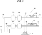
- the water quality measuring system 100 of the first embodiment shown in FIG. 3 is a system for measuring the properties of the rearing water stored in the rearing tank 50.
- the rearing water is water which is used for rearing an aquatic organism and which contains salt contents (for example, seawater, brackish water, artificial seawater, or the like).
- the water quality measuring system 100 measures the concentrations of measurement targets (ammonia gas, nitrous acid gas, ammonium ion, nitrite ion, nitrate ion, etc.) contained in the rearing water.
- the water quality measuring system 10 includes a first sensor section 110, a second sensor section 120, the control apparatus 12, a first flow line 130, a second flow line 140, a first pump 150, a second pump 160, a first filtration section 180, a second filtration section 190, etc.
- the water quality measuring system 100 sucks the rearing water within a sampling container 170 by using the first pump 150 and the second pump 160 so that the rearing water flows through the first flow line 130 and the second flow line 140.
- the rearing water flowing through the first flow line 130 and the rearing water flowing through the second flow line 140 are introduced into the first sensor section 110 and the second sensor section 120, respectively, so as to measure the concentrations of the measurement targets contained in the rearing water.
- the rearing water which is a sampling target, is sampled from the rearing tank 50 and is stored in the sampling container 170.
- the first pump 150 is a well-known pump and is provided in the first flow line 130.
- the first pump 150 pumps the rearing water from the sampling container 170 to the first flow line 130 and feeds the pumped rearing water through the first filtration section 180 to a first introduction section (introduction section) 131 communicating with the first sensor section 110.
- the first filtration section 180 removes foreign substances from the rearing water by filtration.
- the first introduction section 131 is a passage for introducing the rearing water (sampling target) into the first sensor section 110.
- the second pump 160 is a well-known pump and is provided in the second flow line 140.
- the second pump 160 pumps the rearing water from the sampling container 170 to the second flow line 140 and feeds the pumped rearing water through the second filtration section 190 to a second introduction section (introduction section) 141 communicating with the second sensor section 120.
- the second filtration section 190 removes foreign substances from the rearing water by filtration.
- the second introduction section 141 is a passage for introducing the rearing water (sampling target) into the second sensor section 120. Upstream portions of the first flow line 130 and the second flow line 140 may be replaced with a common line, and the flow of the rearing water may be divided into two lines by using a valve or the like before flowing into the first sensor section 110 and the second sensor section 120.
- the first sensor section 110 shown in FIG. 4 measures the concentrations of the measurement targets (ammonia gas, nitrous acid gas, ammonium ion, nitrite ion) contained in the rearing water flowing through the first flow line 130.
- the first sensor section 110 includes the calcium sensor (measurement section) 22, the magnesium sensor (measurement section) 24, the nitrous acid sensor 28, the ammonia sensor 26, and a reference electrode 111.
- the calcium sensor 22 is provided in the first flow line 130 to be located downstream of and adjacent to the first introduction section 131.
- the calcium sensor 22 includes an ion electrode 22A and a first potentiometer 22B.
- the ion electrode 22A is configured, for example, in the form of a well-known liquid membrane ion electrode.
- the ion electrode 22A has an electrode film which selectively reacts with calcium ion and generates an electromotive force in response to the ion concentration.
- the ion electrode 22A is immersed into the rearing water flowing through the first flow line 130 on the downstream side of the first introduction section 131.
- the ion electrode 22A generates an electrode potential in response to the calcium ion concentration of the rearing water.
- the first potentiometer 22B is electrically connected to the ion electrode 22A and the reference electrode 111.
- the reference electrode 111 is an electrode which is configured in the form of a well-known reference electrode (comparison electrode) and generates a standard potential which serves as a reference for the electrode potential of the ion electrode 22A.
- the reference electrode 111 is provided in the first flow line 130 to be located downstream of and adjacent to the ammonia sensor 26, which will be described later.
- the first potentiometer 22B measures the difference between the electrode potential of the ion electrode 22A and the electrode potential of the reference electrode 111 and outputs a measurement result (a signal indicating a potential difference in response to the calcium ion concentration of the rearing water) to the control apparatus 12.
- the magnesium sensor 24 is provided in the first flow line 130 to be located downstream of and adjacent to the calcium sensor 22 (specifically, the ion electrode 22A).
- the magnesium sensor 24 includes an ion electrode 24A and a second potentiometer 24B.
- the ion electrode 24A is configured, for example, in the form of a liquid membrane ion electrode.
- the ion electrode 24A is immersed into the rearing water flowing through the first flow line 130 on the downstream side of the ion electrode 22A.
- the ion electrode 24A generates an electrode potential in response to the magnesium ion concentration of the rearing water having passed through the calcium sensor 22.
- the second potentiometer 24B is electrically connected to the ion electrode 24A and the reference electrode 111.
- the second potentiometer 24B measures the difference between the electrode potential of the ion electrode 24A and the electrode potential of the reference electrode 111 and outputs a measurement result (a signal indicating a potential difference in response to the magnesium ion concentration of the rearing water) to the control apparatus 12.
- the nitrous acid sensor 28 measures the nitrous acid (measurement target) concentration of the rearing water after addition of an acid to the rearing water by a first adding section 132.
- the nitrous acid sensor 28 is provided in the first flow line 130 to be located downstream of and adjacent to the magnesium sensor 24, which is provided downstream of and adjacent to the magnesium sensor 24.
- the first adding section 132 is a passage for adding an acid (for example, sulfuric acid) to the rearing water introduced by the first introduction section 131.
- an acid for example, sulfuric acid
- nitrite ion contained in the rearing water can be transformed into nitrous acid gas.
- the pH of the rearing water is adjusted to 1.5 or lower by adding an acid to the rearing water by the first adding section 132.
- the nitrous acid sensor 28 is configured in the form of a well-known diaphragm type ion sensor and includes an ion electrode 28A and a third potentiometer 28B.
- the ion electrode 28A is configured in the form of a well-known diaphragm type ion electrode.
- the ion electrode 28A is configured, for example, such that nitrous acid gas passing through a diaphragm is dissolved into an electrolytic solution within the electrode, and an electromotive force in response to the pH of the internal solution which changes due to nitrous acid gas is generated. In this manner, the ion electrode 28A can detect nitrous acid gas selectively.
- the ion electrode 28A is immersed into the rearing water flowing through the first flow line 130 on the downstream side of the first adding section 132.
- the ion electrode 28A generates an electrode potential in response to the concentration of nitrous acid gas contained in the rearing water having passed through the first adding section 132 (namely, nitrous acid gas which is composed of nitrous acid gas contained in the rearing water from the beginning before passing through the first adding section 132 and nitrous acid gas transformed from nitrite ion as a result of passage through the first adding section 132).
- the third potentiometer 28B is electrically connected to the ion electrode 28A and the reference electrode 111.
- the third potentiometer 28B measures the difference between the electrode potential of the ion electrode 28A and the electrode potential of the reference electrode 111 and outputs a measurement result (a signal indicating the potential difference in response to the concentration of the gas composed of nitrous acid gas contained in the rearing water from the beginning and nitrous acid gas transformed from nitrite ion) to the control apparatus 12.
- the ammonia sensor 26 measures the ammonia (measurement target) concentration of the rearing water after addition of a base by a second adding section 133.
- the ammonia sensor 26 is provided in the first flow line 130 to be located downstream of and adjacent to the second adding section 133, which is provided downstream of and adjacent to the nitrous acid sensor 28.
- the second adding section 133 is a passage for adding a base (for example, sodium hydroxide aqueous solution) to the rearing water introduced by the first introduction section 131.
- a base for example, sodium hydroxide aqueous solution
- ammonium ion contained in the rearing water can be transformed into ammonia gas.
- the pH of the rearing water is adjusted to 11.5 or higher by adding a base to the rearing water at the second adding section 133.
- the ammonia sensor 26 is configured in the form of a well-known diaphragm type ion sensor and includes an ion electrode 26A and a fourth potentiometer 26B.
- the ion electrode 26A is configured in the form of a well-known diaphragm type ion electrode.
- the ion electrode 26A is configured, for example, such that ammonia gas passing through a diaphragm is dissolved into an electrolytic solution within the electrode, and an electromotive force in response to the pH of the internal solution which changes due to ammonia acid gas is generated. In this manner, the ion electrode 26A can detect ammonia gas selectively.
- the ion electrode 26A is immersed into the rearing water flowing through the first flow line 130 on the downstream side of the second adding section 133.
- the ion electrode 26A generates an electrode potential in response to the concentration of ammonia gas contained in the rearing water having passed through the second adding section 133 (namely, ammonia gas which is composed of ammonia gas contained in the rearing water from the beginning before passing through the second adding section 133 and ammonia gas transformed from ammonium ion as a result of passage through the second adding section 133).
- the fourth potentiometer 26B is electrically connected to the ion electrode 26A and the reference electrode 111.
- the fourth potentiometer 26B measures the difference between the electrode potential of the ion electrode 26A and the electrode potential of the reference electrode 111 and outputs a measurement result (a signal indicating the potential difference in response to the concentration of the gas composed of ammonia gas contained in the rearing water from the beginning and ammonia gas transformed from ammonium ion) to the control apparatus 12.
- the rearing water having passed through the ammonia sensor 26 is discharged from a first discharge section 134 after passing through the reference electrode 111.
- the control apparatus 12 calculates the calcium ion concentration on the basis of the measurement result (signal indicating the potential difference in response to the calcium ion concentration of the rearing water) output from the calcium sensor 22 and stores the calcium ion concentration in the storage section 40. Similarly, the control apparatus 12 calculates the magnesium ion concentration on the basis of the measurement result (signal indicating the potential difference in response to the magnesium ion concentration of the rearing water) output from the magnesium sensor 24 and store the magnesium ion concentration in the storage section 40.
- control apparatus 12 calculates the nitrous acid gas concentration on the basis of the measurement result (signal indicating the potential difference in response to the concentration of the gas composed of nitrous acid gas contained in the rearing water from the beginning and nitrous acid gas transformed from nitrite ion) output from the nitrous acid sensor 28 and stores the nitrous acid concentration in the storage section 40.
- control apparatus 12 calculates the ammonia gas concentration on the basis of the measurement result (signal indicating the potential difference in response to the concentration of the gas composed of ammonia gas contained in the rearing water from the beginning and ammonia gas transformed from ammonium ion) output from the ammonia sensor 26 and stores the ammonia gas concentration in the storage section 40.
- the control apparatus 12 transmits pieces of information regarding these concentrations stored in the storage section 40 to other apparatuses through the communication section 36, displays the pieces of information on the display section 42, and prints the pieces of information by using the printing section 44.
- the second sensor section 120 shown in FIG. 5 measures the measurement target (nitrite ion contained in the rearing water from the beginning and nitrite ion transformed from nitrate ion) concentration of the rearing water flowing through the second flow line 140.
- the second sensor section 120 is provided in the second flow line 140.
- the second sensor section 120 includes the nitric acid sensor 30.
- the nitric acid sensor 30 is configured in the form of a well-known color sensor.
- the nitric acid sensor 30 obtains color information (information which specifies a color) of liquid (measurement target).
- the second flow line 140 introduces the rearing water to be sampled into the second sensor section 120 through a second introduction section 141, which is a passage different from the first introduction section 131.
- An adjustment section 142 is provided in the second flow line 140 to be located downstream of and adjacent to the second introduction section 141.
- the adjustment section 142 is a passage for adding a reducing agent (for example, zinc) to the rearing water introduced by the second introduction section 141.
- a reducing agent for example, zinc
- a color forming section 143 is provided downstream of and adjacent to the adjustment section 142.
- the color forming section 143 is a passage for adding a color former (for example, naphthylethylenediamine) to the rearing water containing the reducing agent added by the adjustment section 142.
- the rearing water develops a color when the color former reacts with nitrite ion.
- the color former causes the rearing water to develop a color in response to the nitrite ion concentration of the rearing water.
- a measurement area 144 is provided downstream of and adjacent to the color forming section 143.
- the measurement area 144 is an area where the rearing water having passed through the color forming section 143 is temporarily stored.
- the nitric acid sensor 30 is disposed in the vicinity of the measurement area 144 so that the rearing water becomes the measurement target of the nitric acid sensor 30.
- the nitric acid sensor 30 obtains the color information (information which specifies a color) of the rearing water.
- the nitric acid sensor 30 outputs the obtained color information to the control apparatus 12.
- the rearing water having passed through the measurement area 144 is discharged from a second discharge section 145.
- the control apparatus 12 calculates the concentration of nitrite ion (nitrite ion contained in the rearing water from the beginning and nitrite ion transformed from nitrate ion) on the basis of the color information output from the nitric acid sensor 30 (information representing a color in response to the nitrite ion concentration of the rearing water) and stores the calculated nitrite ion concentration in the storage section 40.
- pieces of information representing colors which are produced by nitrite ion-containing water as a result of addition of the color former for example, each piece of information is obtained by quantifying the light and shadow of color
- pieces of information representing different nitrite ion concentrations are stored in the storage section 40 beforehand in such a manner that the pieces of information representing colors are related to the pieces of information representing different nitrite ion concentrations.
- the control apparatus 12 calculates the nitrite ion concentration from the color information output from the nitric acid sensor 30 on the basis of the correspondence relationship stored in the storage section 40.
- the control apparatus 12 calculates the nitrate ion concentration of the rearing water (sampling target) on the basis of the measurement target concentration (nitrous acid gas concentration and nitrite ion concentration) detected by the first sensor section 110 and the color of the rearing water detected by the nitric acid sensor 30.
- the control apparatus 12 calculates the nitrate ion concentration of the rearing water (sampling target) on the basis of the nitrous acid gas concentration detected by the first sensor section 110 (the concentration of a gas composed of nitrous acid gas contained in the rearing water from the beginning and nitrous acid gas transformed from nitrite ion) and the nitrite ion concentration calculated from the color information output from the nitric acid sensor 30 (the concentration of nitrite ion, including nitrite ion contained in the rearing water from the beginning and nitrite ion transformed from nitrate ion).
- the control apparatus 12 determines the nitrate ion concentration of the rearing water (sampling target) by subtracting the nitrous acid gas concentration detected by the first sensor section 110 (the concentration of a gas composed of nitrous acid gas contained in the rearing water from the beginning and nitrous acid gas transformed from nitrite ion) from the nitrite ion concentration calculated from the color information output from the nitric acid sensor 30 (the concentration of nitrite ion, including nitrite ion contained in the rearing water from the beginning and nitrite ion transformed from nitrate ion).
- the control apparatus 12 stores the calculated nitrate ion concentration in the storage section 40.
- the control apparatus 12 transmits a piece of information regarding the calculated nitrate ion concentration to other apparatuses through the communication section 36, displays the pieces of information on the display section 42, and prints the pieces of information by using the printing section 44.
- an acid is added by the first adding section 132 to the rearing water introduced by the first introduction section 131, whereby nitrite ion contained in the rearing water can be transformed to nitrous acid gas.
- the nitrous acid gas produced in this manner can be detected selectively by the nitrous acid sensor 28. As a result, it is possible to prevent adverse effect of ions still contained in the water on detection of nitrous acid, thereby enabling accurate measurement of the nitrous acid concentration.
- the water quality measuring system 100 is configured in such a manner that an acid is added by the first adding section 132 to the rearing water introduced by the first introduction section 131, whereby the pH of the rearing water is adjusted. Since it is unnecessary to perform a preliminary treatment for pH adjustment for the entire rearing water (from which sample rearing water is obtained) before being introduced into the first introduction section 131, an environment in which the aquatic organism is reared is unlikely to be adversely effected.
- this water quality measuring system 100 suppresses the influence of disturbances (aeration, movement of organisms, etc.) more easily as compared with a configuration in which a direct-insertion-type sensor is used for the rearing water (from which sample rearing water is obtained) before being introduced into the first introduction section 131.
- a base is added by the second adding section 133 to the rearing water introduced by the first introduction section 131, whereby ammonium ion contained in the rearing water can be transformed to ammonia gas.
- the ammonia gas produced in this manner can be detected selectively by the ammonia sensor 26. As a result, it is possible to prevent adverse effect of ions still contained in the water on detection of ammonia, thereby enabling accurate measurement of the ammonia concentration.
- the water quality measuring system 100 is configured in such a manner that an acid is added by the second adding section 133 to the rearing water introduced by the first introduction section 131, whereby the pH of the rearing water is adjusted. Since it is unnecessary to perform a preliminary treatment for pH adjustment for the entire rearing water (from which sample rearing water is obtained) before being introduced into the first introduction section 131, the environment in which the aquatic organism is reared is unlikely to be adversely effected.
- this water quality measuring system 100 suppresses the influence of disturbances (aeration, movement of organisms, etc.) more easily as compared with a configuration in which a direct-insertion-type sensor is used for the rearing water (from which sample rearing water is obtained) before being introduced into the first introduction section 131.
- the above-described water quality measuring system 100 includes the second introduction section 141 for introducing the rearing water (sampling target) through a passage different from the first introduction section 131; the adjustment section 142 for adding a reducing agent to the rearing water introduced by the second introduction section 141; the color forming section 143 for adding a color former, which reacts with nitrite ion and develops a color, to the rearing water containing the reducing agent added by the adjustment section 142; the nitric acid sensor 30 for measuring the color of the rearing water containing the color former added by the color forming section 143; and the control apparatus 12 for calculating the nitrate ion concentration of the rearing water (sampling target) on the basis of the measurement target concentration detected by the nitrous acid sensor 28 and the color of the rearing water detected by the nitric acid sensor 30.
- This water quality measuring system 100 can convert nitrate ion contained in the rearing water to nitrite ion by causing the adjustment section 142 to add a reducing agent to the rearing water introduced by the second introduction section 141. Since the water quality measuring system 100 is configured to cause the color forming section 143 to add a color former, which reacts with nitrite ion and develops a color, to the rearing water whose pH has been adjusted in this manner, the pH adjusted rearing water develops a color corresponding to the nitrite ion concentration.
- control apparatus 12 can calculate the nitrate ion concentration of the rearing water on the basis of the measurement target concentration (nitrous acid concentration) detected by the nitrous acid sensor 28 and the color of the rearing water detected by the nitric acid sensor 30.
- the above-described water quality measuring system 100 includes the first filtration section 180 and the second filtration section 190 for filtering the rearing water.
- the first sensor section 110 measures the measurement target concentration of the rearing water filtered by the first filtration section 180
- the second sensor section 120 measures the measurement target concentration of the rearing water filtered by the second filtration section 190.
- the calcium sensor 22 measures the concentration of a component (calcium ion) which is contained in the rearing water before passing through the first adding section 132 and the second adding section 133 and which differs from the measurement target.
- the magnesium sensor 24 measures the concentration of a component (magnesium ion) which is contained in the rearing water before passing through the first adding section 132 and the second adding section 133 and which differs from the measurement target.
- the concentrations of components (calcium ion and magnesium ion) different from the measurement target are measured by the calcium sensor 22 and the magnesium sensor 24 before the pH of the rearing water is adjusted by the first adding section 132 and the second adding section 133. Therefore, the concentrations of components (calcium ion and magnesium ion) different from the measurement target can be measured without receiving the influence of pH adjustment and the influence of a component added for pH adjustment.
- the control apparatus 12 calculates the nitrate ion concentration by subtracting the nitrous acid gas concentration detected by the first sensor section 110 (the concentration of a gas composed of nitrous acid gas contained in the rearing water from the beginning and nitrous acid gas transformed from nitrite ion) from the nitrite ion concentration calculated from the color information output from the nitric acid sensor 30.
- the control apparatus 12 may calculate the nitrate ion concentration by subtracting only the concentration of nitrous acid gas transformed from nitrite ion from the nitrite ion concentration calculated from the color information output from the nitric acid sensor 30.
- the concentration of nitrous acid gas contained in the rearing water from the beginning is measured by the nitrous acid sensor 28 without addition of an acid to the rearing water from the first introduction section 131.
- the concentration of nitrous acid gas transformed from nitrite ion can be determined by subtracting the concentration of nitrous acid gas contained in the rearing water from the beginning, which is measured without addition of an acid, from the nitrous acid gas concentration detected by the first sensor section 110 described in the first embodiment (the concentration of a gas composed of nitrous acid gas contained in the rearing water from the beginning and nitrous acid gas transformed from nitrite ion).
- the ammonia gas concentration and the nitrous acid gas concentration are measured.
- the ammonium ion concentration and the nitrous acid ion concentration can be calculated from the measured ammonia gas concentration and nitrous acid gas concentration, the pH, the temperature, and the ionization constants of ammonia and nitrous acid, which are well known.
- prawn is shown as an example of the aquatic organism cultured in the production system Sy.
- the aquatic organism may be an organism (other than prawn) of Decapoda , Malacostraca , Crustacea, or Arthropoda.
- the reduction treatment may be performed by a well-known method such as electrolytic reduction.
- the calcium ion concentration and the magnesium ion concentration are measured in the first sensor section 110 before the rearing water flows through the first adding section 132.
- the present invention is not limited to such a configuration.
- calcium ion and magnesium ion may be measured in the second sensor section 120 before the rearing water flows through the adjustment section 142.
- control apparatus 12 the communication section 36, the operation section 38, the storage section 40, the display section 42, the printing section 44 are incorporated into the single information processing apparatus 11.
- the present invention is not limited to such a configuration. Some sections of the information processing apparatus 11 may be separated and data and instructions may be exchanged between the information processing apparatus 11 and the separated sections by wired or wireless communication.
Landscapes
- Life Sciences & Earth Sciences (AREA)
- Chemical & Material Sciences (AREA)
- Health & Medical Sciences (AREA)
- Physics & Mathematics (AREA)
- General Health & Medical Sciences (AREA)
- Immunology (AREA)
- General Physics & Mathematics (AREA)
- Pathology (AREA)
- Analytical Chemistry (AREA)
- Biochemistry (AREA)
- Engineering & Computer Science (AREA)
- Chemical Kinetics & Catalysis (AREA)
- Molecular Biology (AREA)
- Electrochemistry (AREA)
- Medicinal Chemistry (AREA)
- Food Science & Technology (AREA)
- Environmental Sciences (AREA)
- Organic Chemistry (AREA)
- Hydrology & Water Resources (AREA)
- Environmental & Geological Engineering (AREA)
- Water Supply & Treatment (AREA)
- Plasma & Fusion (AREA)
- Biomedical Technology (AREA)
- Marine Sciences & Fisheries (AREA)
- Animal Husbandry (AREA)
- Biodiversity & Conservation Biology (AREA)
- Investigating Or Analyzing Non-Biological Materials By The Use Of Chemical Means (AREA)
- Farming Of Fish And Shellfish (AREA)
- Treatment Of Water By Oxidation Or Reduction (AREA)
Applications Claiming Priority (2)
| Application Number | Priority Date | Filing Date | Title |
|---|---|---|---|
| JP2019131015A JP7027379B2 (ja) | 2019-07-16 | 2019-07-16 | 水質計測システム |
| PCT/JP2020/027386 WO2021010400A1 (ja) | 2019-07-16 | 2020-07-14 | 水質計測システム |
Publications (2)
| Publication Number | Publication Date |
|---|---|
| EP4001909A1 true EP4001909A1 (de) | 2022-05-25 |
| EP4001909A4 EP4001909A4 (de) | 2023-08-23 |
Family
ID=74210840
Family Applications (1)
| Application Number | Title | Priority Date | Filing Date |
|---|---|---|---|
| EP20841118.1A Withdrawn EP4001909A4 (de) | 2019-07-16 | 2020-07-14 | Wasserqualitätsmesssystem |
Country Status (6)
| Country | Link |
|---|---|
| US (1) | US20220268726A1 (de) |
| EP (1) | EP4001909A4 (de) |
| JP (1) | JP7027379B2 (de) |
| CN (1) | CN114207424A (de) |
| PH (1) | PH12022550072A1 (de) |
| WO (1) | WO2021010400A1 (de) |
Families Citing this family (6)
| Publication number | Priority date | Publication date | Assignee | Title |
|---|---|---|---|---|
| US12313618B2 (en) * | 2021-02-12 | 2025-05-27 | Hach Company | Predictive model for water quality deterioration |
| NO347871B1 (no) * | 2021-05-12 | 2024-04-22 | Searas As | System og fremgangsmåte for å måle mengde NH3 oppløst i en væske |
| JP7682830B2 (ja) * | 2022-04-08 | 2025-05-26 | 愛三工業株式会社 | 水質検査装置及び飼育システム |
| WO2025057504A1 (ja) * | 2023-09-13 | 2025-03-20 | 日本特殊陶業株式会社 | 水質モニタリングシステム |
| JP7838759B2 (ja) * | 2023-09-28 | 2026-04-01 | 青木あすなろ建設株式会社 | 貝類の養殖システムおよび養殖方法 |
| JP2025104514A (ja) * | 2023-12-28 | 2025-07-10 | 日本特殊陶業株式会社 | 甲殻類の陸上養殖における水質管理システムおよび甲殻類の生産方法 |
Family Cites Families (17)
| Publication number | Priority date | Publication date | Assignee | Title |
|---|---|---|---|---|
| US4297173A (en) * | 1980-05-22 | 1981-10-27 | Ajinomoto Company, Incorporated | Method for determining ammonia and sensor therefor |
| DE3727384A1 (de) * | 1987-08-17 | 1989-03-02 | Basf Ag | Redoxelektrode zur bestimmung von salpetriger saeure und nitrosylverbindungen |
| JP2557152B2 (ja) * | 1991-11-05 | 1996-11-27 | 工業技術院長 | 濃度測定方法 |
| JPH0678648A (ja) * | 1992-01-31 | 1994-03-22 | Amazon Marine:Kk | 活魚輸送システム |
| JPH0646718A (ja) * | 1992-08-03 | 1994-02-22 | Yokogawa Electric Corp | 活魚生命維持装置 |
| JP2000146899A (ja) | 1998-11-06 | 2000-05-26 | Horiba Ltd | アンモニウムイオン測定装置 |
| JP2003052275A (ja) * | 2001-08-13 | 2003-02-25 | Eruson Kk | 魚介類の養殖方法および閉鎖循環式養殖システム |
| US6936156B2 (en) * | 2001-08-30 | 2005-08-30 | The United States Of America As Represented By The Secretary Of The Department Of The Interior | Automated self-calibrating water quality monitoring sensor housing assembly |
| JP2003075424A (ja) * | 2001-08-31 | 2003-03-12 | Horiba Ltd | 窒素化合物分析方法および窒素化合物分析装置 |
| JP4223799B2 (ja) * | 2001-12-19 | 2009-02-12 | 株式会社東芝 | バイオセンサ型水質監視システム及び装置 |
| JP2003254925A (ja) | 2002-03-06 | 2003-09-10 | Horiba Ltd | 隔膜式ガスセンサ |
| KR20050111069A (ko) * | 2004-05-20 | 2005-11-24 | (주) 휴마스 | 해수분석용 총질소, 질산성질소, 아질산성질소 분석시약의조성물 및 분석방법 |
| JP5586972B2 (ja) | 2009-01-30 | 2014-09-10 | 株式会社明電舎 | 亜硝酸性窒素測定方法及びその装置 |
| KR101346664B1 (ko) * | 2012-05-23 | 2014-01-02 | 주식회사 씨맥 | 질산성 질소 농도 검출방법 |
| CN107340249A (zh) * | 2017-07-05 | 2017-11-10 | 安徽皖仪科技股份有限公司 | 一种在线检测环境水样中总氮含量的方法 |
| JP7373426B2 (ja) * | 2020-02-12 | 2023-11-02 | 日本特殊陶業株式会社 | 水質計測装置及び水質計測装置の保管方法 |
| JP7352497B2 (ja) * | 2020-03-09 | 2023-09-28 | 日本特殊陶業株式会社 | 水質計測装置用の校正液、水質計測装置用の校正液入り容器、及び水質計測装置用の校正液を用いる校正方法。 |
-
2019
- 2019-07-16 JP JP2019131015A patent/JP7027379B2/ja active Active
-
2020
- 2020-07-14 EP EP20841118.1A patent/EP4001909A4/de not_active Withdrawn
- 2020-07-14 WO PCT/JP2020/027386 patent/WO2021010400A1/ja not_active Ceased
- 2020-07-14 CN CN202080051079.4A patent/CN114207424A/zh active Pending
- 2020-07-14 US US17/627,518 patent/US20220268726A1/en not_active Abandoned
- 2020-07-14 PH PH1/2022/550072A patent/PH12022550072A1/en unknown
Also Published As
| Publication number | Publication date |
|---|---|
| JP7027379B2 (ja) | 2022-03-01 |
| PH12022550072A1 (en) | 2022-11-21 |
| JP2021013908A (ja) | 2021-02-12 |
| US20220268726A1 (en) | 2022-08-25 |
| EP4001909A4 (de) | 2023-08-23 |
| WO2021010400A1 (ja) | 2021-01-21 |
| CN114207424A (zh) | 2022-03-18 |
Similar Documents
| Publication | Publication Date | Title |
|---|---|---|
| EP4001909A1 (de) | Wasserqualitätsmesssystem | |
| CA1277370C (en) | Method of measuring the effective inhibitor concentration during a deposition of metal from aqueous electrolytes and an apparatus therefor | |
| CN107703124A (zh) | 尿素浓度检测方法及尿素浓度在线监测设备 | |
| CN114206106B (zh) | 养殖系统 | |
| EP4038381B1 (de) | Messung von chlor in meerwasser | |
| RU2579383C2 (ru) | Устройство и способ снижения содержания пероксида водорода и перуксусной кислоты в водном потоке | |
| Galimova et al. | Inversion-chronopotentiometric analysis of mercury in water | |
| CN104977393A (zh) | 一种船舶压载水处理系统用在线有效氯检测仪及检测方法 | |
| EP4143558A1 (de) | Nachweis von oxidationsmittel in meerwasser | |
| JP2015504777A (ja) | バラスト水を処理するための方法及び装置 | |
| KR20130008828A (ko) | 센서를 이용한 잔류염소농도의 측정방법과 측정장치 및 그를 이용한 정수처리시스템 | |
| Stiller et al. | A novel respirometer for online detection of metabolites in aquaculture research: evaluation and first applications | |
| EP4119936A1 (de) | Kalibrierflüssigkeit für wasserqualitätsmessgerät, mit kalibrationsflüssigkeit gefüllter behälter für wasserqualitätsmessgerät und kalibrierverfahren mit der kalibrierflüssigkeit für wasserqualitätsmessgerät | |
| Huu et al. | Propose an automatic ammonia concentration of water measuring system combining image processing for aquaculture | |
| CN207488193U (zh) | 一种用于光电比色法的余氯检测装置 | |
| EP4735871A1 (de) | Abschwächung von freier chlorinterferenz zur ozondetektion unter verwendung eines indigobasierten indikators | |
| WO2024118716A1 (en) | Indigo-based indicator detection of ozone | |
| CN107884465B (zh) | 一种用于赤潮早期预警的在线监测系统及方法 | |
| CN211122834U (zh) | 一种可测光照强度的溶解氧监测系统 | |
| Nie et al. | Livestock and Aquaculture Information Sensing Technology | |
| Li et al. | Performance evaluation of the amperometric total residual oxidant sensor with the electrochlorination-based Ballast Water Management System | |
| CN115015485A (zh) | 微酸性电解水发生器出水有效氯浓度在线监测模型、系统 | |
| KR100956810B1 (ko) | 산화환원전위 센서를 이용한 수중 산화물 제어방법 및 그 장치 | |
| CN204807542U (zh) | 一种船舶压载水处理系统用在线有效氯检测仪 | |
| KR20110019407A (ko) | 질산화 박테리아를 이용한 생태 독성 감지 시스템 |
Legal Events
| Date | Code | Title | Description |
|---|---|---|---|
| STAA | Information on the status of an ep patent application or granted ep patent |
Free format text: STATUS: THE INTERNATIONAL PUBLICATION HAS BEEN MADE |
|
| PUAI | Public reference made under article 153(3) epc to a published international application that has entered the european phase |
Free format text: ORIGINAL CODE: 0009012 |
|
| STAA | Information on the status of an ep patent application or granted ep patent |
Free format text: STATUS: REQUEST FOR EXAMINATION WAS MADE |
|
| 17P | Request for examination filed |
Effective date: 20220114 |
|
| AK | Designated contracting states |
Kind code of ref document: A1 Designated state(s): AL AT BE BG CH CY CZ DE DK EE ES FI FR GB GR HR HU IE IS IT LI LT LU LV MC MK MT NL NO PL PT RO RS SE SI SK SM TR |
|
| DAV | Request for validation of the european patent (deleted) | ||
| DAX | Request for extension of the european patent (deleted) | ||
| REG | Reference to a national code |
Ref country code: DE Ref legal event code: R079 Free format text: PREVIOUS MAIN CLASS: G01N0027416000 Ipc: A01K0063040000 |
|
| RAP3 | Party data changed (applicant data changed or rights of an application transferred) |
Owner name: NITERRA CO., LTD. |
|
| A4 | Supplementary search report drawn up and despatched |
Effective date: 20230725 |
|
| RIC1 | Information provided on ipc code assigned before grant |
Ipc: C02F 1/44 20060101ALN20230719BHEP Ipc: C02F 1/32 20060101ALN20230719BHEP Ipc: C02F 1/24 20060101ALN20230719BHEP Ipc: G01N 33/18 20060101ALI20230719BHEP Ipc: C02F 9/00 20060101ALI20230719BHEP Ipc: A01K 63/04 20060101AFI20230719BHEP |
|
| STAA | Information on the status of an ep patent application or granted ep patent |
Free format text: STATUS: EXAMINATION IS IN PROGRESS |
|
| 17Q | First examination report despatched |
Effective date: 20250918 |
|
| STAA | Information on the status of an ep patent application or granted ep patent |
Free format text: STATUS: THE APPLICATION HAS BEEN WITHDRAWN |
|
| 18W | Application withdrawn |
Effective date: 20251230 |