EP4002057A1 - Scharnieranordnung und führungsanordnung für elektronische vorrichtungen unter verwendung eines wärmeleitenden elements - Google Patents
Scharnieranordnung und führungsanordnung für elektronische vorrichtungen unter verwendung eines wärmeleitenden elements Download PDFInfo
- Publication number
- EP4002057A1 EP4002057A1 EP21197807.7A EP21197807A EP4002057A1 EP 4002057 A1 EP4002057 A1 EP 4002057A1 EP 21197807 A EP21197807 A EP 21197807A EP 4002057 A1 EP4002057 A1 EP 4002057A1
- Authority
- EP
- European Patent Office
- Prior art keywords
- chassis
- guide
- hinge
- carrying member
- heat carrying
- Prior art date
- Legal status (The legal status is an assumption and is not a legal conclusion. Google has not performed a legal analysis and makes no representation as to the accuracy of the status listed.)
- Granted
Links
Images












Classifications
-
- G—PHYSICS
- G06—COMPUTING OR CALCULATING; COUNTING
- G06F—ELECTRIC DIGITAL DATA PROCESSING
- G06F1/00—Details not covered by groups G06F3/00 - G06F13/00 and G06F21/00
- G06F1/16—Constructional details or arrangements
- G06F1/1613—Constructional details or arrangements for portable computers
- G06F1/1633—Constructional details or arrangements of portable computers not specific to the type of enclosures covered by groups G06F1/1615 - G06F1/1626
- G06F1/1675—Miscellaneous details related to the relative movement between the different enclosures or enclosure parts
- G06F1/1681—Details related solely to hinges
-
- G—PHYSICS
- G06—COMPUTING OR CALCULATING; COUNTING
- G06F—ELECTRIC DIGITAL DATA PROCESSING
- G06F1/00—Details not covered by groups G06F3/00 - G06F13/00 and G06F21/00
- G06F1/16—Constructional details or arrangements
- G06F1/1613—Constructional details or arrangements for portable computers
-
- G—PHYSICS
- G06—COMPUTING OR CALCULATING; COUNTING
- G06F—ELECTRIC DIGITAL DATA PROCESSING
- G06F1/00—Details not covered by groups G06F3/00 - G06F13/00 and G06F21/00
- G06F1/16—Constructional details or arrangements
- G06F1/1613—Constructional details or arrangements for portable computers
- G06F1/1615—Constructional details or arrangements for portable computers with several enclosures having relative motions, each enclosure supporting at least one I/O or computing function
- G06F1/1616—Constructional details or arrangements for portable computers with several enclosures having relative motions, each enclosure supporting at least one I/O or computing function with folding flat displays, e.g. laptop computers or notebooks having a clamshell configuration, with body parts pivoting to an open position around an axis parallel to the plane they define in closed position
- G06F1/1618—Constructional details or arrangements for portable computers with several enclosures having relative motions, each enclosure supporting at least one I/O or computing function with folding flat displays, e.g. laptop computers or notebooks having a clamshell configuration, with body parts pivoting to an open position around an axis parallel to the plane they define in closed position the display being foldable up to the back of the other housing with a single degree of freedom, e.g. by 360° rotation over the axis defined by the rear edge of the base enclosure
-
- G—PHYSICS
- G06—COMPUTING OR CALCULATING; COUNTING
- G06F—ELECTRIC DIGITAL DATA PROCESSING
- G06F1/00—Details not covered by groups G06F3/00 - G06F13/00 and G06F21/00
- G06F1/16—Constructional details or arrangements
- G06F1/20—Cooling means
- G06F1/203—Cooling means for portable computers, e.g. for laptops
-
- G—PHYSICS
- G06—COMPUTING OR CALCULATING; COUNTING
- G06F—ELECTRIC DIGITAL DATA PROCESSING
- G06F2200/00—Indexing scheme relating to G06F1/04 - G06F1/32
- G06F2200/20—Indexing scheme relating to G06F1/20
- G06F2200/203—Heat conductive hinge
Definitions
- This disclosure relates in general to the field of computing, and more particularly, to a hinge assembly and a guide assembly for electronic devices using a heat carrying member.
- a heat carrying member can spread the heat produced by heat sources from one area of an electronic device to another area and thus enable more effective heat dissipation from the device.
- Various embodiments disclosed herein improve heat dissipation by a heat carrying member that is extended between two chassis (e.g., lid and base, primary display and secondary display, etc.) of an electronic device (e.g., a laptop, a notebook, a dual display system, a convertible laptop/tablet, etc.).
- a guide unit provides a passage area through which a heat carrying member and possibly a flexible printed circuit (FPC) can be extended between the two chassis.
- FPC flexible printed circuit
- a hinge assembly can include a single guide unit configured to ensure that a curve length of a heat carrying member remains substantially the same when one chassis is rotated relative to the other chassis (or as both chassis are rotated relative to each other).
- a different guide unit is coupled to each chassis and a separate hinge may facilitate rotation of one chassis relative to the other.
- a heat carrying member and optionally, a flexible printed circuit (FPC) can be secured to the two guide units to maintain a curve length of the heat carrying member and the FPC and to prevent deformations as a chassis is rotated about the hinge.
- Heat sources such as compute devices (e.g., processors, graphical processing units, etc.) and other high power components are often concentrated within one chassis (e.g., a base, a secondary display chassis, etc.) of an electronic device, while the other chassis (e.g., a lid with a display, a primary display chassis, etc.) houses relatively low power components.
- the bulk of the thermal demands may originate in the chassis that houses the major heat sources.
- Cooling the heat sources in an electronic device such as a laptop can be complicated, especially when the heat sources are concentrated in a particular chassis.
- a fan may be used to cool system components.
- a fan requires a certain amount of real estate within the device, however, while current trends in electronic devices are moving toward thinner and lighter designs. Consequently, for some electronic device designs, the real estate needed to accommodate a fan may not be available or desirable, or some other reason (e.g., cost, design choice, increase in power consumption, etc.) may prevent the inclusion of a fan in the design.
- passively cooled systems is an ultrathin three hundred sixty degree (360°) convertible device.
- heat is dissipated from the base because the base contains the most significant heat sources. Heat dissipation from the system may be limited to the surface area available on one chassis.
- one use of a convertible device involves the base lying flat against a surface such as a table or desk. Such use can hinder heat dissipation as air flow through and around the chassis may be limited. Thus, heat produced in a base that houses high power components may not be sufficiently dissipated to protect the integrity of those components. If cooling is shared with another chassis, however, the cooling capacity may be increased by 25-30% in some estimations and device performance may be significantly improved.
- One method of sharing cooling between two chassis of an electronic device includes extending a heat carrying member from one chassis to another chassis to spread the heat from the dominant heat producing chassis to the other chassis. Avoiding damage to a heat carrying member in a device due to repeatedly opening and closing the device, however, can present significant challenges.
- a sheet of graphite is used as a heat carrying member in an electronic device and is also used as a driver to displace a moving member to ensure that the graphite layers' minimum bend radius is maintained throughout the entire movement of a lid (i.e., from 0° to 360° angles of rotation) relative to a base of the electronic device.
- a heat carrying member to act as a driver of another moving member, however, may cause stress on the graphite layer and require a thick reinforcement by a microfabric layer to prevent tearing or degradation of the graphite sheet.
- a thick heat carrying member may compromise the space available for a flexible printed circuit (FPC), a battery, and other components.
- Another concern in electronic device designs involves achieving a desirable screen to body ratio. Higher screen to body ratio may be constrained in thinner devices by hinge cable routing space requirements. Lesser wire routing space availability at the hinge is another key design limiter.
- a hinge assembly for systems using a heat carrying member between rotatable chassis can solve these issues (and more).
- a hinge assembly 106 as shown in FIG. 1A offers an improved approach for effectively sharing cooling in systems having two (or more) chassis that are rotatable relative to each other.
- Such systems can include, but are not necessarily limited to convertible systems where the range of motion of a chassis relative to another chassis may be from zero degrees to three hundred sixty degrees (0°-360°), or typical display systems where the range of motion of one chassis relative to another chassis may be from zero degrees (0°) to one hundred eighty degrees (180°) or somewhat less.
- the hinge assembly is configured to allow a heat carrying member to extend from one chassis of the system (e.g., a lid or primary display), through a guide unit of the hinge assembly, and into a second chassis of the system (e.g., a base or second display).
- the hinge assembly is further configured to ensure that an overall length (also referred to herein as 'curve length') of a middle portion of the heat carrying member is maintained as the middle portion transforms from a first curve to a generally inverted curve when the first and/or second chassis is rotated from a closed position (e.g., 0°) to a fully rotated position (e.g., 360°) and vice versa.
- the hinge assembly can use a uniquely designed cam element fitted to an existing hinge rotation mechanism (e.g., of a 360° convertible system) that interacts with a spring-loaded moving guide unit.
- the specially designed cam profile prevents stress (e.g., stretching, taughtness, bending, etc.) from happening to the heat carrying member throughout the range of motion of one or both chassis from a closed position (e.g., 0°) to a fully rotated position (e.g., 360°) and vice versa.
- the heat carrying member may be a graphite layer that carries and spreads the heat, and the graphite layer may be at least partially enclosed in a protective layer such as microfabric.
- a microfabric-graphite-microfabric layer sandwich may help prevent any wear and tear of the graphite layers.
- a hinge assembly for systems using heat carrying members as shown and described herein can provide many advantages.
- the hinge assembly can be used in compute devices (e.g., convertibles or typical display systems, etc.) with higher performance of the system on a chip (SOC) in ultrathin systems, for example, where the system is approximately 10-11mm in thickness.
- the specially designed cam can be retrofitted to an existing hinge with slight modification.
- the hinge assembly provides an easy way to route flexible printed circuits (FPCs) when sandwiched between microfabric material layers. Since the heat carrying member avoids stress in this hinge assembly design, a thinner protective membrane, such as a microfabric layer, can be potentially be used to cover the heat carrying member, which may be a graphite sheet for example.
- the specially designed guide unit may allow for a slight inclination of the base (e.g., 3-5o) when the base is arranged on a substantially flat surface such as a table or desk. This configuration can provide an improved user keyboard experience.
- Hinge assembly 106 can rotatably couple first chassis 102 to second chassis 104.
- First chassis 102 may be capable of rotation relative to second chassis 104
- second chassis 104 may be capable of rotation relative to first chassis 102.
- electronic device 100 is convertible, in which first chassis 102 is rotatable between zero degrees (0°) and three hundred sixty degrees (360°) relative to second chassis 104, and/or second chassis 104 is rotatable between zero degrees (0°) and three hundred sixty degrees (360°) relative to first chassis 102.
- electronic device 100 is illustrated as a convertible laptop, embodiments herein may be implemented in numerous other types of devices that are not necessarily convertible.
- a convertible laptop may have a range of rotation from zero to three hundred sixty degrees (0°-360°)
- other devices implemented with hinge assembly 106 with movable guide unit 120 can have less than a three hundred sixty degree (360°) range of rotation.
- a typical laptop may have a first chassis that has a range of rotation from zero to approximately one hundred eighty degrees (0°-180°) relative to a second chassis.
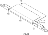
- Heat carrying member 110 can extend from within first chassis 102, through hinge assembly 106, into second chassis 104.
- Heat carrying member 110 includes a first chassis portion 112 disposed in first chassis 102, a second chassis portion 114 disposed in second chassis 104, and a middle portion 116 extending through hinge assembly 106 and disposed between the first chassis and the second chassis.
- first chassis portion 112 of heat carrying member 110 may be disposed behind a display (shown in FIG. 1C ) contained in first chassis 102.
- second chassis portion 114 of heat carrying member 110 may be disposed behind a keyboard, a second display, or any other outwardly facing user interface or other components contained in second chassis 104.
- Heat carrying member 110 may be configured to facilitate shared cooling between first chassis 102 and second chassis 104.
- Heat sources 108 can include compute (e.g., central processing unit (CPU), graphical processing unit (GPU), etc.) and other high power components, for example.
- Second chassis portion 114 of heat carrying member 110 can be configured to receive heat from heat sources 108 and to transfer at least some of the heat received from heat sources 108 to first chassis portion 112 of heat carrying member 110 by the heat flowing through middle portion 116 to first chassis portion 112.
- First chassis 102 may provide additional surface area through which the thermal energy that spreads into first chassis portion 112 can escape.
- heat carrying member 110 can facilitate heat dissipation via the surface areas of first chassis 102, in addition to heat dissipation already occurring in second chassis 104. Consequently, heat produced in one area (e.g., heat sources 108) can be spread across electronic device 100, which can increase cooling capacity and prevent damage to heat sources 108 and other components in close proximity to heat sources 108.
- heat carrying member 110 can be securely attached to the two chassis.
- first chassis portion 112 of heat carrying member 110 may be securely attached within first chassis 102
- second chassis portion 114 of heat carrying member 110 may be securely attached within second chassis 104.
- Any suitable attachment means may be used to securely attach heat carrying member 110 to first chassis 102 and second chassis 104 (e.g., fasteners, screws, nuts, bolts, adhesive, etc.).
- Such attachment means may attach the heat carrying member directly to the two chassis and/or to one or more components or elements within two chassis.
- Middle portion 116 of heat carrying member 110 can be permitted to float and may not be securely attached to any particular structure between an inner edge 103 of first chassis 102 and an inner edge 105 of second chassis 104, where the inner edge of first chassis 102 is generally parallel to and opposes the inner edge of second chassis 104.
- middle portion 116 may not be securely attached to movable guide unit 120.
- FIG. 1B is an isometric view of convertible electronic device 100 in a closed position.
- First chassis portion 112 of heat carrying member 110 is shown extending into first chassis 102.
- Middle portion 116 of heat carrying member 110 forms a generally curved profile in the closed position.
- first chassis portion 112 of heat carrying member 110 is illustrated in a generally rectangular shape sized to extend across a large area of first chassis 102, first chassis portion 112 may be different dimensions and/or shapes, depending on particular implementations and needs of electronic device 100.
- first chassis 102 and second chassis 104 are substantially parallel and thus define an angle of rotation of zero degrees (0°) relative to each other. From an open position, such as the open position shown in FIG.
- first chassis 102 may be rotated generally about hinge assembly 106 toward second chassis 104 until first chassis 102 is substantially parallel to second chassis 104 and no angle is defined in between. In the closed position, a display contained in first chassis 102 can oppose second chassis 104 such that the display is at least partially hidden from view.
- second chassis 104 may contain a keyboard, touchpad, or other user interface, or a second display opposing the display in first chassis 102.
- FIG. 1C is an isometric view of convertible electronic device 100 in a fully rotated position.
- Middle portion 116 of heat carrying member 110 forms a generally curved profile in the fully rotated position.
- first chassis 102 and second chassis 104 are substantially parallel and define an angle of approximately three hundred sixty degrees (360°).
- first chassis 102 may be rotated approximately three hundred sixty (360°) relative to second chassis 104 until first chassis 102 is substantially parallel to second chassis 104.
- a display 109 contained in first chassis 102 faces outwardly, away from second chassis 104, to provide a tablet configuration.
- the curved profile of middle portion 116 of heat carrying member 110 is generally inverted from the curved profile of the middle portion when the electronic device is in the closed position.
- the middle portion 116 adapts to the profiles of guide members provided in hinge assembly 106, which will be shown and described herein. Without proper support in hinge assembly 106, heat carrying member 110 (and especially the middle portion 116) could be damaged during the rotational movement of one chassis relative to the other. For example, rotational movement of a chassis may cause heat carrying member 110 to experience a bend, warp, fold, crease, or other deformity.
- Hinge assembly 106 is designed to substantially or totally prevent stress to the heat carrying member while simultaneously preventing deformation of the heat carrying member during rotational movement of the first chassis relative to the second chassis, or vice versa, or simultaneous rotational movement of the first and second chassis.
- Hinge assembly 106 is configured to accommodate heat carrying member in a rotational range from a closed position at zero degrees (0°), in which middle portion 116 adapts to a first profile of curved surface of a first guide member of hinge assembly 106, to a fully rotated position at three hundred sixty degrees (360°), in which middle portion 116 adapts to a generally inverted second profile of a second guide member of hinge assembly 106.
- a flexible printed circuit may also be routed from second chassis 104, through hinge assembly 106, to first chassis 102.
- the FPC may replace one or more cables that carry electrical signals between chassis 102 and 104.
- an FPC may carry electrical signals from a CPU or GPU in second chassis 104 to a display 109 in first chassis 102.
- Touch screen functionalities in display 109 may detect input at display 109 and carry electrical signals representing the touch input to compute elements in second chassis 104.
- electronic device 100 is intended to include a computer, a laptop (e.g., clamshell with screen on one of its inner sides and a user interface such as a keyboard on the opposite inner side facing the display), subnotebook or ultraportable (e.g., a laptop having a smaller more portable design) or ultraportable, a netbook (e.g., laptop especially suited for wireless communication), a convertible (e.g., device with combination of features from laptops and tablets), desktop replacement (e.g., larger device that is a transportable alternative to a desktop computer), rugged laptop (e.g., laptop designed to work in harsh conditions), business laptop (e.g., designed for use in a workplace), a personal digital assistant (PDA), an electronic notebook, a mobile phone, or any other device having a heat source (e.g., CPUs, GPUs, memory elements, displays, etc.), and at least two chassis, where at least one of the chassis is rotatable about a hinge relative to the other chassis.
- a heat source
- At least one additional protective layer may be used between protective layers 118 and heat carrying member 110.
- These additional protective layers may be made from a nickel titanium ally (e.g., nitinol) or from a thin plastic later (e.g., polypropylene) and may be configured having 0.15 mm maximum thickness, in one possible example.
- protective layers 118 and optionally, the additional protective layers as described herein may also be employed to protect a flexible printed circuit (FPC) if an FPC is implemented with hinge assembly 106.
- FPC flexible printed circuit
- first and second shafts 182 and 184 may have complementary elements provided on the opposite or left side of hinge assembly 106.
- These complementary elements on the opposite side of hinge assembly 106 may also be covered by an end frame 160.
- longitudinal axes of first and second shafts coupled to hinge brackets on the left side of hinge assembly 106 can be aligned with the longitudinal axes of first and second shafts 182 and 184, respectively, which are shown in FIG. 3B .
- FIG. 3D is an exploded view of hinge assembly 106 according to one or more embodiments.
- hinge assembly 106 can include movable guide unit 120, end frames 160, outer frame 150, and rotation mechanisms 170.
- Movable guide unit 120 includes first guide member 122, second guide member 124, guide end portions 128, and longitudinal extensions 130.
- First guide member 122 may be at least generally shaped as a half-cylinder.
- Second guide member 124 may be at least generally shaped as a half-cylinder.
- Biasing member 138 can extend through the elongated cavity and may abut an interior surface of upper housing 134.
- biasing members can be configured as compression springs surrounding frame extensions 158.
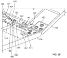
- Hinge assembly 106 also includes cams 190 on each side of movable guide unit 120. Rotation mechanisms 170 on each end of hinge assembly 106 show second hinge brackets 174 for coupling to second shafts 184. Torque elements 187 are shown connected to second shafts 184. Second shafts can include distal ends 186 fitted within cams 190 in an interference fit.
- Outer frame 150 may include a bottom plate 152, side extension pairs 156, and frame extensions 158 extending through movable guide unit 120 to slidably connect movable guide unit 120 to outer frame 150.
- Bottom plate 152 may include frame brackets 154 at each end, which may be connected to end frames 160.
- a moving means can move movable guide unit 120 such that guide unit 120 (and more specifically, the passage area 126 defined by guide unit 120) traverses hinge plane 188 in a first linear direction as indicated by directional arrow 196a. More generally, during at least some rotational movement of first chassis 102 about first shaft 182, which causes an angle of rotation relative to second chassis 104 to decrease, movable guide unit 120 can move through hinge plane 188 in the first linear direction toward outer frame 150.
- the movement of movable guide unit 120 is configured to cause the curve length formed in middle portion 116 of heat carrying member 110 between first chassis inner edge 103 and second chassis inner edge 105 to remain substantially the same during the rotational movement of first chassis 102 that causes an angle of rotation relative to the second chassis 104 to decrease.
- the movement of movable guide unit 120 is configured to cause the curve length of middle portion 116 of heat carrying member 110 between first chassis inner edge 103 and second chassis inner edge 105 to remain substantially the same during the rotational movement of first chassis 102 that causes an angle of rotation relative to the second chassis 104 to increase.
- Outer frame 150 can be secured to end frame 160, for example, by frame brackets 154 (shown in FIG. 3D , for example) attached to end frame 160 at a bottom side or flanges, for example.
- Heat carrying member 110 can extend from first chassis 102, through movable guide unit 120 of hinge assembly 106, and into second chassis 104.
- Middle portion 116 of heat carrying member 110 can be disposed, at least partially, within passage area 126 defined between the convex surfaces of first guide member 122 and second guide member 124.
- FIG. 7B illustrates a cross-sectional view of hinge assembly 106 when first chassis 102 has been rotated relative to second chassis 104 to increase an angle of rotation to approximately forty-five degrees (45°) from a lesser angle of rotation (e.g., from 0°).
- the means for moving movable guide unit 120 may be configured to hold movable guide unit 120 adjacent to bottom plate 152 of outer frame 150 and thus, to hold the midpoint of the convex surface of first guide member 122 in alignment with hinge plane 188 (shown in FIG. 6A , for example).
- first chassis 102 when first chassis 102 is rotated to ninety degrees (90°) from a lesser angle of rotation, the simultaneous rotation of cam 190 may be configured such that the cam remains positioned against ramp portion 140 to overcome the bias of biasing member 138 and thus prevent biasing member from moving guide unit 120.
- Middle section 116 of heat carrying member 110 may begin to separate from the edges of the convex surface of first guide member 122 as first chassis 102 is rotated to ninety degrees (90°).
- rotation of first chassis 102 to ninety degrees (90°) relative to second chassis 104 can result in rotation of hinge plane 188 to approximately one hundred thirty-five degrees (135°) relative to second chassis 104.
- first chassis 102 when first chassis 102 is rotated to one hundred thirty-five degrees (135°) from a lesser angle of rotation, the simultaneous rotation of cam 190 may allow the bias of biasing member 138 to begin to move movable guide unit 120 away from bottom plate 152 and to cause the guide unit and specifically, the passage area 126 defined by guide unit 120, to traverse hinge plane 188 in a first linear direction such that first guide member 122 begins to move away from hinge plane 188 and second guide member 124 begins to move toward hinge plane 188.
- Middle portion 116 of heat carrying member 110 can follow increasingly less of the convex surface of first guide member 122 as first chassis 102 increases its angle of rotation relative to second chassis 104.
- rotation of first chassis 102 to one hundred thirty-five degrees (135°) relative to second chassis 104 can result in rotation of hinge plane 188 to approximately one hundred fifty-seven and one-half degrees (157.5°) relative to second chassis 104.
- first chassis 102 when first chassis 102 is rotated to two hundred seventy degrees (270°) from a lesser angle of rotation, the simultaneous rotation of cam 190 may allow the bias of biasing member 138 to move movable guide unit 120 further away from bottom plate 152 and cause the guide unit to traverse hinge plane 188 in the first linear direction such that first guide member 122 moves further away from hinge plane 188 and second guide member 124 moves closer to hinge plane 188.
- Middle portion 116 of heat carrying member 110 can follow more of the convex surface of second guide member 124 as first chassis 102 is rotated.
- rotation of first chassis 102) to two hundred seventy degrees (270°) relative to second chassis 104 can result in rotation of hinge plane 188 to approximately two hundred twenty-five degrees (225°) relative to second chassis 104.
- Movement of the offset outer portion 194 causes the rotational force of second shaft 184 to be translated into a linear force in which the bias of biasing member 138 against longitudinal extension 130 of movable guide unit 120 causes ramp portion 140 to move in a first linear direction away from bottom plate 152 of outer frame 150, and causes upper angled surface 144 of ramp portion 140 to follow outer portion 194 of cam 190 as it eccentrically rotates about the second hinge axis.
- second guide member 124 which is coupled to ramp portion 140, also moves in the first linear direction away from bottom plate 152 of outer frame 150, as shown in FIG. 7E .
- FIG. 8C illustrates a cross-sectional view of hinge assembly 106 at cam 190 when first chassis 102 has been rotated relative to second chassis 104 to increase an angle of rotation to approximately two hundred seventy degrees (270°) from a lesser angle of rotation (e.g., from 225°).
- first chassis 102 is rotated to two hundred seventy degrees (270°) from a lesser angle of rotation
- the inner portion 192 of cam 190 may be rotated about its longitudinal axis by second shaft 184.
- the rotation of inner portion 192 causes offset outer portion 194 of cam 190 to further rotate eccentrically relative to the longitudinal axis of inner portion 192 (e.g., second hinge axis), and thus to be further directed away from upper angled surface 144 of ramp portion 140.
- Movement of the offset outer portion 194 causes the rotational force of second shaft 184 to be translated into a linear force in which the bias of biasing member 138 against longitudinal extension 130 of movable guide unit 120 causes ramp portion 140 to move in the first linear direction further away from bottom plate 152 of outer frame 150, and causes upper angled surface 144 of ramp portion 140 to follow outer portion 194 of cam 190 as it eccentrically rotates about the second hinge axis.
- second guide member 124 which is coupled to ramp portion 140, also moves in the first linear direction further away from bottom plate 152 of outer frame 150, as shown in FIG. 7G .
- FIG. 8E illustrates a cross-sectional view of hinge assembly 106 at cam 190 when first chassis 102 has been rotated relative to second chassis 104 to increase an angle of rotation to approximately three hundred sixty degrees (360°) from a lesser angle of rotation (e.g., from 270°).
- first chassis 102 is rotated to three hundred sixty degrees (360°) from a lesser angle of rotation
- the inner portion 192 of cam 190 may be rotated about its longitudinal axis by second shaft 184.
- the rotation of inner portion 192 causes offset outer portion 194 of cam 190 to further rotate eccentrically relative to the longitudinal axis of inner portion 192 (e.g., second hinge axis), and thus to be further directed away from upper angled surface 144 of ramp portion 140.
- Movement of the offset outer portion 194 causes the rotational force of second shaft 184 to be translated into a linear force in which the bias of biasing member 138 against longitudinal extension 130 of movable guide unit 120 causes ramp portion 140 to move in the first linear direction further away from bottom plate 152 of outer frame 150, and causes upper angled surface 144 of ramp portion 140 to follow outer portion 194 of cam 190 as it eccentrically rotates about the second hinge axis.
- second guide member 124 which is coupled to ramp portion 140, also moves in the first linear direction further away from bottom plate 152 of outer frame 150, as shown in FIG. 7I .
- FIG. 9 is a line graph 900 illustrating the change in a curve length of the middle portion of heat carrying member 110 during rotational movement of a first chassis (e.g., 102) relative to a second chassis (e.g., 104) when an angle of rotation increases from zero degrees (0°) (e.g., in the closed position) to one hundred eighty degrees (180°).
- the curve length formed in middle portion 116 is approximately 26 mm, as indicated at 910. Without the movable guide unit 120 in hinge assembly 106, during rotation of first chassis 102 relative to second chassis 104, the curve length formed in middle portion 116 experiences some minimal reduction, as shown by line 920. In the closed position, the curve length formed in middle portion 116 is reduced to approximately 25.8mm, as indicated at 922. At ninety degrees (90°), the length is reduced to approximately 25.5mm as indicated at 924. At one hundred eighty degrees (180°), the length is increased to approximately 25.75mm, as indicated at 926.
- FIG. 10 is a line graph 1000 illustrating the change in a curve length formed in the middle portion 116 of heat carrying member 110 during rotational movement of a first chassis (e.g., 102) relative to a second chassis (e.g., 104) when an angle of rotation increases from one hundred eighty degrees (180°) to three hundred sixty degrees (360°) (e.g., in the fully rotated position).
- the curve length formed in middle portion 116 is approximately 26mm, as indicated at 1010.
- a convertible system when rotated from one hundred eighty degrees (180°) to three hundred sixty degrees (360°), there can be a drastic change in the curve length in a middle portion (e.g., 116) of a heat carrying member (e.g., 110).
- the curve length could experience significant reduction.
- the heat carrying member In the absence of movable guide unit 120, the heat carrying member can form kinks, folds, or bends as a result of the slack created in the heat carrying member.
- the middle portion 116 may experience, for example, folding at random points, creases, and cutting of the creases.
- first chassis 102 when first chassis 102 is oriented at one hundred eighty degrees (180°) relative to second chassis 104, the curve length formed in middle portion 116 may be reduced to approximately 25.67mm.
- first chassis 102 When first chassis 102 is rotated to two hundred seventy degrees (270°), the curve length may be reduced to approximately 23.67mm, as indicated at 1022.
- first chassis 102 When first chassis 102 is rotated to three hundred sixty degrees (360°), the length may be reduced to approximately 23.25mm as indicated at 1024.
- the profile of cam 190 works against the spring-loaded movable guide unit 120 to compensate for the slack and to allow the heat carrying member to follow the profile of guide member 122 (or guide member 124 when rotating to the closed position). Consequently, during rotation of first chassis 102 relative to second chassis 104 between one hundred eighty degrees (180°) and three hundred sixty degrees (360°), the movable guide unit functions as a tensioning mechanism to prevent folding and to tension the slack in heat carrying member 110 that results from the rotation. As shown at 1010, the middle portion 116 can maintain the overall curve length of approximately 26mm. In one example, guide unit 120 may be moved (e.g., away/toward outer frame 150, through hinge plane 188) by approximately 1.5mm to ensure that the overall curve length is maintained.
- a side section 153 of outer frame 150 can be spaced below a substantially planar, lower side of second chassis 104 to lift the hinge end of the second chassis and create a tilt of approximately three degrees (3°) from the table.
- side section 153 can be a side corner, a rounded edge, or any other shape of the outer frame that is suitable for engaging a surface (e.g., 198) to tilt the hinge end of second chassis forward at a slight angle. The tilt can create an ergonomic experience for a user.
- Such an angle can improve comfort when typing or using another user interface (e.g., trackball, mouse, touchscreen, etc.) on second chassis 104.
- a desirable tilt can be achieved when bottom plate 152 of outer frame 150 is configured to be approximately 2mm from side section 153 of second chassis 104 when first chassis 102 is positioned at a one hundred eighty degree (180°) angle of rotation from second chassis 103 .
- a guide assembly 1210 and a side hinge 1250 offer an improved approach for effectively sharing cooling in systems having two (or more) chassis that are rotatable relative to each other.
- Such systems can include, but are not necessarily limited to convertible systems where the range of motion of a chassis relative to another chassis may be from zero degrees to three hundred sixty degrees (0°-360°), or typical display systems where the range of motion of one chassis relative to another chassis may be from zero degrees (0°) to one hundred eighty degrees (180°) or slightly less.
- the guide assembly is configured to allow a heat carrying member to extend from one chassis of the system (e.g., a lid or first display), through two guide units (also referred to herein as "rollers") of the guide assembly, and into a second chassis of the system (e.g., a base or second display).
- the guide assembly is further configured to ensure that the overall length of a heat carrying member is maintained, and that stress on the heat carrying member is prevented, as one or both of the first and second chassis of the system are rotated from a closed position (e.g., 0°, or some other minimum angle of rotation for a particular device) to a fully rotated position (e.g., 180°, 360°, or some other maximum angle of rotation for a particular device) or vice versa.
- the guide assembly includes an alternative embodiment of a guide unit.
- the guide assembly may include two generally parallel guide units (also referred to herein as "rollers") between side hinges.
- a heat carrying member passes through both rollers and can be securely attached to at least one roller.
- Each roller may be coupled to a respective chassis and rotatable with respect to a hinge axis associated with the chassis.
- a roller can be tilted during rotation of its chassis.
- the heat carrying member may be a graphite layer that carries and spreads the heat, and the graphite layer may be at least partially enclosed in a protective layer such as microfabric. Placement of the side hinge on the outer sides of each chassis opens up wished space within the real estate of each chassis. Accordingly, in addition to the heat carrying member, electrical signals may be routed through the guide assembly via a flexible printed circuit.
- a side hinge may include two gears, such as spur gears for example, with interlocking teeth.
- the guide assembly can offer numerous advantages for electronic devices that use a heat carrying member to spread heat between two chassis.
- the mechanism can allow the heat carrying member and FPC to maintain their respective lengths through the range of rotation (e.g., 0°-360°), without inducing unnecessary stress on the heat carrying member or the FPC.
- the guide assembly and side hinge enable ergonomic comfort preferences to be attained and/or requirements associated with relative temperatures between two displays (e.g., dual display device) or compartments to be fulfilled.
- the guide assembly can protect a user from the risk of touching a hot surface.
- thinner converged mobility devices are enabled because the guide assembly and side hinge provide more space to accommodate both a heat carrying member and a flexible printed circuit (FPC) to route electrical signals rather than common cables being routed across displays in different chassis.
- the number of cables may also be reduced by allowing partial FPC cross routing.
- the hinge supply chain can achieve independence by eliminating cables from the hinge assembly. Accordingly, cables are prevented from damage when an FPC is used with a guide assembly.
- the cost of the guide assembly may decrease and the yield rate may increase.
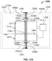
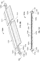
- FIG. 12A is a plan view of a convertible electronic device 1200 in an open position in which first chassis 1202 and second chassis 1204 are configured at an angle of approximately one hundred eighty degrees (180°).
- Electronic device 1200 is configured with a guide assembly 1220, side hinges 1250, a heat carrying member 1210, and a flexible printed circuit (FPC) 1240 according to one or more embodiments.
- electronic device 1200 may be a dual display device, including a first chassis 1202 containing a first display 1209a and a second chassis 1204 containing a second display 1209b.
- second chassis 1204 may house significant heat sources 1208 such as compute (e.g., central processing unit (CPU), graphics processing unit (GPU), etc.) and other high power components, for example.
- compute e.g., central processing unit (CPU), graphics processing unit (GPU), etc.
- GPU graphics processing unit
- First chassis 1202 may be capable of rotation relative to second chassis 1204, and second chassis 1204 may be capable of rotation relative to first chassis 1202.
- electronic device 1200 is convertible, in which first chassis 1202 is rotatable between zero degrees (0°) and three hundred sixty degrees (360°) relative to second chassis 1204, and/or second chassis 1204 is rotatable between zero degrees (0°) and three hundred sixty degrees (360°) relative to first chassis 1202.
- first chassis 1202 is rotatable between zero degrees (0°) and three hundred sixty degrees (360°) relative to second chassis 1204, and/or second chassis 1204 is rotatable between zero degrees (0°) and three hundred sixty degrees (360°) relative to first chassis 1202.
- electronic device 1200 is illustrated as a convertible laptop, embodiments herein may be implemented in numerous other types of devices that are not necessarily convertible.
- a convertible laptop may have a range of rotation from zero to three hundred sixty degrees (0°-360°) between the first chassis and second chassis
- other devices implemented with guide assembly 1220 and/or side hinge 1250 can have less than a three hundred sixty degree (360°) range of rotation.
- a typical laptop may have a first chassis with a display that has a range of rotation from zero to approximately one hundred eighty degrees (0°-180°) relative to a second chassis with a keyboard.
- first roller 1222a is rotatably coupled to first chassis 1202 by any suitable means to enable the first roller to rotate as the first chassis is rotated.
- a circular hole or projection may be configured to enable rotation.
- end caps 1230a can be received in guide cavities defined by first chassis guide holders 1206a that protrude from an inner edge of first chassis 1202 to couple first roller 1222a to first chassis 1202.
- second roller 1222b can have the same or substantially the same configuration as second roller 1222b.
- Second roller 1222b can include a first guide shaft 1224b, a second guide shaft 1225b (shown in FIG. 14B , for example), and end caps 1230b.
- End caps 1230b can be configured to support first guide shaft 1224b and second guide shaft 1225b in a parallel, spaced apart arrangement such that middle portion 1216 of heat carrying member 1210 and/or middle FPC portion 1246 of FPC 1240 may be disposed therebetween.
- Second roller 1222b is rotatably coupled to second chassis 1204 by any suitable means to enable the second roller to rotate as the second chassis is rotated. For example, a circular hole or projection may be configured to enable rotation.
- end caps 1230b can be received in guide cavities defined by second chassis guide holders 1206b that protrude from an inner edge of second chassis 1204 to couple second roller 1222b to second chassis 1204.
- Heat carrying member 1210 can extend from first chassis 1202, through guide assembly 1220, to second chassis 1204.
- Heat carrying member 1210 includes a first chassis portion 1212 disposed in first chassis 1202, a second chassis portion 1214 disposed in second chassis 1204, and middle portion 1216 extending through a first roller 1222a in first chassis 1202 and through a second roller 1222b in second chassis 1204.
- first chassis portion 1212 of heat carrying member 1210 may be disposed behind first display 1209a contained in first chassis 1202
- second chassis portion 1214 of heat carrying member 1210 may be disposed behind second display 1209b contained in second chassis 1204.
- Heat carrying member 1210 is configured to facilitate shared cooling between first chassis 1202 and second chassis 1204.
- Heat sources 1208 can include compute (e.g., central processing unit (CPU), graphical processing unit (GPU), etc.) and other high power components, for example.
- Second chassis portion 1214 of heat carrying member 1210 can be configured to receive heat from heat sources 1208 and to transfer at least some of the heat received from heat sources 1208 to first chassis portion 1212 of heat carrying member 1210 by the heat flowing through middle portion 1216 to first chassis portion 1212.
- First chassis 1202 may provide additional surface area through which the thermal energy that spreads into first chassis portion 1212 can escape.
- heat carrying member 1210 facilitates heat dissipation via the surface areas of first chassis 1202, in addition to heat dissipation already occurring in second chassis 1204. Consequently, heat produced in one area (e.g., heat sources 1208) can be spread across electronic device 1200, which can increase cooling capacity and prevent damage to heat sources 1208 and other components in close proximity to heat sources 1208.
- heat carrying member 1210 can be securely attached to the two chassis.
- first chassis portion 1212 of heat carrying member 1210 may be securely attached within first chassis 1202
- second chassis portion 1214 of heat carrying member 1210 may be securely attached within second chassis 1204.
- Any suitable attachment means may be used to securely attach heat carrying member 1210 to first chassis 1202 and second chassis 1204 (e.g., fasteners, screws, nuts, bolts, adhesive, etc.).
- Such attachment means may attach the heat carrying member directly to the two chassis or to one or more components or elements within first chassis 1202 and/or second chassis 1204.
- Middle portion 1216 of heat carrying member 1210 may also be fixedly attached to first guide shaft 1224a, second guide shaft 1225a, or both first and second guide shafts 1224a and 1225a.
- FPC 1240 can also extend from first chassis 1202, through guide assembly 1220, and to second chassis 1204.
- FPC 1240 includes a first FPC portion 1242 disposed in first chassis 1202, a second FPC portion 1244 disposed in second chassis 1204, and a middle FPC portion 1246 extending through first roller 1222a in first chassis 1202 and through second roller 1222b in second chassis 1204.
- first FPC portion 1242 of FPC 1240 may be disposed behind and operably connected to first display 1209a contained in first chassis 1202
- second FPC portion 1244 of FPC 1240 may be disposed behind and operably connected to second display 1209b contained in second chassis 1204.
- the FPC may replace one or more cables that carry electrical signals between chassis 1202 and 1204.
- an FPC may carry electrical signals from a CPU or GPU in second chassis 1204 (e.g., part of heat sources 1208) to display 1209a in first chassis 1202.
- Touch screen functionalities in display 1209a may detect input and FPC 1240 may carry electrical signals representing the touch input to compute elements in second chassis 1204.
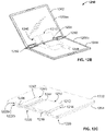
- FIG. 12B is an isometric interior view of a convertible electronic device 1200 in an open position.
- FIG. 12B illustrates the dual displays of convertible electronic device 1200.
- First chassis 1202 and second chassis 1204 are rotatably coupled via side hinges 1250 on each side of first chassis 1202 and second chassis 1204.
- Guide assembly 1220 is disposed between side hinges 1250.
- Guide assembly 1220 includes first roller 1222a coupled to first chassis 1202 at an inner edge of first chassis 1202 and a second roller 1222b coupled to second chassis 1204 at an inner edge of second chassis 1204, where the inner edge of first chassis 1202 opposes the inner edge of second chassis 1204.
- FIG. 12C is an isometric view of convertible electronic device 1200 in a closed position.
- FIG. 12C shows first chassis portion 1212 of heat carrying member 1210 extending into first chassis 1202, second chassis portion 1214 of heat carrying member 1210 extending into second chassis 1204,and middle portion 1216 of heat carrying member 1210 extending through first roller 1222a and second roller 1222b.
- First FPC portion 1242 is shown extending into first chassis 1202
- second FPC portion 1244 is shown extending into second chassis 1204
- middle FPC portion 1246 is shown extending through first roller 1222a and second roller 1222b.
- heat carrying member 1210 is illustrated in a generally rectangular shape sized to extend across a large area of first chassis 1202 and second chassis 1204, heat carrying member 1210 may be different dimensions and shapes, depending on particular implementations and needs of electronic device 1200.
- FPC 1240 may be configured in any suitable size and shape depending on particular implementations and needs.
- first chassis 1202 and second chassis 1204 may have approximately the same thickness (or depth). As shown in FIG. 12C , in the closed position, first chassis 1202 and second chassis 1204 are substantially parallel and thus, define an angle of rotation of zero degrees (0°). From any other position, such as the open position shown in FIG.
- first chassis 1202 may be rotated about side hinges 1250 toward second chassis 1204 until first chassis 1202 is substantially parallel to second chassis 1204 such that no angle is defined between them.
- a display e.g., 1209a
- a display e.g., 1209b
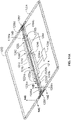
- FIG. 12D is an isometric view of convertible electronic device 1200 in a fully rotated position.
- First chassis portion 1212 of heat carrying member 1210 is shown extending into first chassis 1202
- second chassis portion 1214 of heat carrying member 1210 is shown extending into second chassis 1204, and middle portion 1216 of heat carrying member is shown extending through first roller 1222a and second roller 1222b.
- First FPC portion 1242 is shown extending into first chassis 1202
- second FPC portion 1244 is shown extending into second chassis 1204, and middle FPC portion 1246 is shown extending through first roller 1222a and second roller 1222b.
- first chassis 1202 and second chassis 1204 are substantially parallel and thus, define an angle of rotation of three hundred sixty degrees (360°).
- first chassis 1202 may be rotated about side hinges 1250 toward second chassis 1204 until first chassis 1202 is substantially parallel to second chassis 1204 such that a three hundred sixty degree (360°) angle of rotation is defined between them.
- second display 1209b contained in second chassis 1204 faces outwardly, away from first chassis 1202
- first display 1209a (not shown in FIG. 12D ) contained in first chassis 1202 faces outwardly, away from second chassis 1204.
- middle portion 1216 of heat carrying member 1210 and middle FPC portion 1246 of FPC 1240 each adapt a first a curve when first chassis 1202 is rotated to a closed position and adapt to a generally inverted second curve when first chassis 1202 is rotated to a fully rotated position.
- heat carrying member 1210 and/or FPC 1240 can be damaged during the rotational movement of one chassis relative to the other.
- rotational movement of a chassis may cause heat carrying member 1210 and/or FPC 1240 to experience a bend, warp, fold, crease, or other deformity.
- Some hinges that include support to minimize deformities in a heat carrying member may instead (or in addition) cause stress to be applied to a middle portion and possibly other areas of the heat carrying member that results in stretching, taughtness, tearing, or other degradation of the heat carrying member.
- stress can cause a heat carrying member such as a graphite sheet to lose its properties, which can detrimentally affect its overall performance.
- stress can damage electrical connections configured by FPC 1240.
- Guide assembly 1220 is designed to substantially or totally prevent stress to heat carrying member 1210 and FPC 1240 while simultaneously preventing deformation of the heat carrying member and FPC during rotational movement of the first chassis relative to the second chassis, or vice versa, or simultaneous rotational movement of the first and second chassis.
- First roller 1222a and second roller 1222b of guide assembly 1220 are configured to accommodate a rotational range from a closed position at zero degrees (0°), in which middle portion 1216 forms a first curve profile, to a fully rotated position at three hundred sixty degrees (360°), in which middle portion 1216 transforms to a generally inverted second curve profile.
- middle FPC portion 1246 forms a first curve profile when the device is in the closed position, and transforms to generally inverted second curve profile when the device is rotated to a fully rotated position.
- electronic device 1200 is intended to include a computer, a laptop (e.g., clamshell with screen on one of its inner sides and a user interface such as a keyboard on the opposite inner side facing the display), subnotebook or ultraportable (e.g., a laptop having a smaller more portable design) or ultraportable, a netbook (e.g., laptop especially suited for wireless communication), a convertible (e.g., device with combination of features from laptops and tablets), desktop replacement (e.g., larger device that is a transportable alternative to a desktop computer), rugged laptop (e.g., laptop designed to work in harsh conditions), business laptop (e.g., designed for use in a workplace), a personal digital assistant (PDA), an electronic notebook, a mobile phone, or any other device that includes a heat source (e.g., CPUs, GPUs, memory elements, displays, etc.), and at least two chassis, where at least one of the chassis is rotatable about a hinge relative to the other chassis.
- electronic device 1200 may be implemented as a converged mobility device. Although electronic device 1200 is shown having two displays 1209a and 1209b in first and second chassis 1202 and 1204, respectively, it should be apparent that, in other embodiments, a single display, or more than two displays, may be provided in an electronic device configured with guide assembly 1220 and/or side hinge 1250. Other such embodiments may be configured with two or more chassis at least some of which are rotatable generally about a hinge that connects at least some of the two or more chassis.
- various user interfaces and other components may be provided in one or both of the chassis (or other chassis if configured) such as, for example, a keyboard, a touchpad, a fingerprint sensor, a camera, a microphone, an audio device, and any other user interface or other components.
- FIG. 13 is a cross-sectional view of one example implementation of heat carrying member 1210 for electronic device 1200.
- a "bend area" or “working zone” of heat carrying member 1210 may be sandwiched between first protective layers 1218 and optionally, second protective layers 1219.
- the bend area may comprise middle portion 1216 of heat carrying member 1210 or a part thereof.
- Heat carrying member 1210 may be made of any material having sufficiently high thermal conductivity to enable the heat carrying member to transfer thermal energy from a heat source in one chassis to another chassis, and sufficient yield strength to enable middle portion 1216 of heat carrying member 110 to transform between a first curve profile to a generally inverted second curve profile, repeatedly without breaking or becoming permanently deformed.
- heat carrying member 1210 examples include, but are not necessarily limited to, graphite, copper, and aluminum.
- heat carrying member 1210 may be formed from a graphite sheet of approximately 0.1 mm thickness (or depth) having conductivity greater than 700W/mK.
- Protective layers 1218 and 1219 protect heat carrying member 1210 from physical damage as well as ensuring that the hot surface does not come into contact with a user.
- first protective layers 1218 and optionally, second protective layers 1219 can be bonded to the working zone of heat carrying member 1210.
- first protective layers 1218 and/or second protective layers 1219 can be extended to sandwich at least part of first chassis portion 1212, second chassis portion 1214, or parts of chassis portions 1212 and 1214.
- First and second protective layers 1218 and 1219 may be made of any material that is sufficiently heat-resistant to withstand heat transferred via heat carrying member 1210 and that is strong enough to protect heat carrying member 1210 from wear and tear and other potential external damage.
- protective layers 1218 may be made of a microfabric material, which provides durability and stain resistance. Examples of microfabric material that may be used can include but are not necessarily limited to synthetic fibers such as polyester, polyamides (e.g., nylon, aramid, trogamide, etc.), polypropylenes, or any suitable combination thereof.
- Second protective layers 1219 may be made from a nickel titanium ally (e.g., nitinol) or from a thin plastic later (e.g., polypropylene) and may be configured having 0.15 mm maximum thickness, in one possible example. It should be noted that first protective layers and optionally, second protective layers as described herein may also be employed to protect flexible printed circuit (FPC) 1240 in one or more embodiments.
- FPC flexible printed circuit
- FIG. 14A is isometric interior view of convertible electronic device 1200 in an open position in which first chassis 1202 and second chassis 1204 are configured at an angle of approximately one hundred eighty degrees (180°) relative to each other.
- FIG. 14A shows first chassis 1202 with first display 1209a removed, and second chassis 1204 with second display 1209b removed.
- Electronic device 1200 may include side hinges 1250 to rotatably couple first and second chassis 1202 and 1204, guide assembly 1220, heat carrying member 1210, heat sources 1208, and flexible printed circuit (FPC) 1240.
- Heat carrying member 1210 can include first chassis portion 1212, second chassis portion 1214, and middle portion 1216.
- FPC 1240 can include first FPC portion 1242, second FPC portion 1244, and middle FPC portion 1246.
- Guide assembly 1220 can include first roller 1222a and second roller 1222b.
- axes of side hinges 1250 can be aligned with axes of rollers 1222a and 1222b.
- Heat carrying member 1210 can extend from first chassis 1202, through first roller 1222a, through second roller 1222b, into second chassis 1204.
- First roller 1222a can include first guide shaft 1224a, second guide shaft 1225a (shown in FIG. 15A , for example), and end caps 1230a at each end of first and second guide shafts 1224a and 1225a.
- Second roller 1222b can include first guide shaft 1224b, second guide shaft 1225b, and end caps 1230b at each end of first and second guide shafts 1224b and 1225b.
- Guide cavities defined by first chassis guide holders 1206a (partially shown in FIG. 14A ) can be configured for receiving end caps 1230a of first roller 1222a and rotatably securing first roller 1222a to first chassis 1202.
- Guide cavities defined by second chassis guide holders 1206b (partially shown in FIG. 14A ) can be configured for receiving end caps 1230b of second roller 1222b and rotatably securing second roller 1222b to second chassis 12
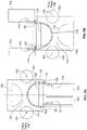
- FIG. 14B is a cut away cross-sectional view of one side of dual guide assembly 1220 in electronic device 1200 shown in FIG. 14A .
- the cross section may be cut through passage areas defined between first guide shaft 1224a and second guide shaft 1225a and between first guide shaft 1224b and second guide shaft 1225b.
- the cross section of first roller 1222a shows second guide shaft 1225a and end cap 1230a attached to one end of second guide shaft 1225a.
- the cross section of second roller 1222b shows second guide shaft 1225b and end cap 1230b attached to one end of second guide shaft 1225b.
- end cap 1230a of first roller 1222a and end cap 1230b of second roller 1222b can each include an inner plug 1232, a spacer 1234, and an outer fastener 1236.
- Inner plug 1232 of end cap 1230a can be configured to receive one end of second guide shaft 1225a (and one end of first guide shaft 1224a shown in FIG. 15A , for example).
- Inner plug 1232 of end cap 1230b can be configured to receive one end of second guide shaft 1225b (and one end of first guide shaft 1224b shown in FIG. 15A , for example).
- Rollers 1222a and 1222b may be screwed or otherwise rotatably connected to their respective chassis 1202 and 1204 to allow one Degree of Freed (DOF), i.e., rotational motion.
- first guide holder 1206a of first chassis 1202 can be configured to define a guide cavity to receive outer fastener 1236 of end cap 1230a such that it can freely rotate.
- first roller 1222a can pivot with first chassis 1202 when the first chassis is rotated.
- Second guide holder 1206b of second chassis 1204 can be configured to define a guide cavity to receive outer fastener 1236 of end cap 1230b such that it can freely rotate.
- second roller 1222b is rotatably coupled to second chassis 1204 and can pivot with second chassis 1204 when the second chassis is rotated.
- FPC 1240 can be secured between first guide shaft 1224a and second guide shaft 1225a of first roller 1222a by, for example, one or more pins 1228a formed in second guide shaft 1225a that are inserted through holes in the FPC 1240 into corresponding, axially aligned openings defined in first guide shaft 1224a.
- FPC 1240 can be secured between first guide shaft 1224b and second guide shaft 1225b of second roller 1222b by, for example, one or more pins 1228b formed in second guide shaft 1225b that are inserted through holes in FPC 1240 into corresponding, axially aligned openings defined in first guide shaft 1224b.
- the passage area defined by the spacing between first guide shaft 1224a and second guide shaft 1225a of first roller 1222a, through which FPC 1240 (and heat carrying member 1210) extend, may be aligned with an opening in first chassis 1202 through which FPC 1240 (and heat carrying member 1210) can be routed.
- the passage area defined by the spacing between first guide shaft 1224b and second guide shaft 1225b of second roller 1222b, through which FPC 1240 (and heat carrying member 1210) extend may be aligned with an opening into second chassis 1204 through which FPC 1240 (and heat carrying member 1210) can be routed.
- FIG. 14C is a side elevation view of one side hinge 1250
- FIG. 14D is a cross-sectional view of side hinge 1450 in electronic device 1200 according to one or more embodiments.
- side hinge 1250 can be attached to left side surfaces (e.g., 1262 and 1264) of first and second chassis 1202 and 1204 that are aligned
- a duplicate side hinge 1250 can be attached to the right side surfaces (not shown in FIGS. 14B-14C ) of the first and second chassis 1202 and 1204 that are aligned.
- the side hinges can rotatably couple first chassis 1202 and second chassis 1204 to each other.
- side hinge 1250 can include a first gear 1252a and a second gear 1252b, which allow first chassis 1202 to be rotated between zero degrees (0°) and three hundred sixty degrees (360°) relative to second chassis 1204.
- Second chassis 1204 may also be rotatable relative to first chassis 1202.
- Shafts 1258 of gears 1252a and 1252b can be connected to torque rings 1259, which operably couple gears 1252a and 1252b to engage and rotate.
- the hinge axes of first gear 1252a and second gear 1252b may be aligned with first roller 1222a and second roller 1222b, respectively (shown in FIG. 14A , for example).
- Side hinge 1250 can include a first bracket 1254a connected to first gear 1252a and a second bracket 1254b connected to second gear 1252b.
- First bracket 1254a can be attached to side surface 1262 of first chassis 1202 using any suitable fastener such as, for example screws 1256.
- Second bracket 1254b can be attached to side surface 1264 of second chassis 1204 using any suitable fastener such as, for example screws 1256.
- the side surface 1262 of first chassis 1202 can be aligned with side surface 1264 of second chassis 1204 and may be spaced to enable interlocking teeth of gears 1252a and 1252b to be rotatably engaged.
- gears 1252a and 1252b may be configured as spur gears.
- any other suitable gears e.g., helical gears, etc.
- Placement of side hinges (such as side hinge 1250) on the aligned side surfaces of an electronic device can enhance the screen-to-body ratio as only the gear mechanism and torque rings are accommodated.
- the configuration and placement of side hinge 1250 also makes space available to enable a flexible printed circuit (FPC) to be routed between first chassis 1202 and second chassis 1204.
- FPC flexible printed circuit
- the use of an FPC can reduce the cables needed to pass electrical signals between the chassis 1202 and 1204.
- Each inner plug 1232 may be configured with two openings to receive an end from first guide shaft 1224a and an end from second guide shaft 1225a.
- Inner plugs 1232 may be configured to support guide shafts 1224a and 1225a in a spaced apart parallel arrangement. The spacing between guide shafts 1224a and 1225a can define a first passage area sized to receive a middle portion 1216 of heat carrying member 1210 and middle FPC portion 1246 of FPC 1240.
- Middle portion 1216 of heat carrying member 1210 and middle FPC portion 1246 of FPC 1240 may be secured between the two guide shafts 1224a and 1225a using any suitable securing means to minimize curve length change of the middle portion 1216 of heat carrying member 1210 and of middle FPC portion 1246.
- multiple pins 1228a may be provided on one guide shaft (e.g., second guide shaft 1225a) and corresponding openings may be defined in the corresponding parallel guide shaft (e.g., first guide shaft 1224a).
- the guide shafts can be oriented in inner plugs 1232 so that the pins in second guide shaft 1225a are facing and axially aligned with the openings in first guide shaft 1224a.
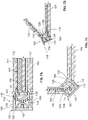
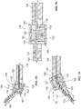
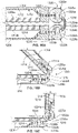
- FIGS. 16A-16F are cross-sectional views of guide assembly 1220 and heat carrying member 1210 in various positions during rotational movement of first chassis 1202 of electronic device 1200 from a closed position to a fully rotated position.
- the cross-sectional views in FIGS. 16A-16F show first roller 1222a, second roller 1222b, and heat carrying member 1210 extending from first chassis 1202, through first roller 1222a, through second roller 1222b, and into second chassis 1204. Cut away views of first chassis 1202 and second chassis 1204 are also shown.
- First roller 1222a may be rotatably coupled to first chassis 1202 by end caps 1230a fixed in first chassis 1202, as shown in FIG. 14B , for example.
- Second roller 1222b can include first guide shaft 1224b and second guide shaft 1225b in a parallel, spaced apart arrangement that defines second passage area 1226b therebetween for receiving middle portion 1216 of heat carrying member 1210.
- Second passage area 1226b can be aligned with a slit opening defined at an inner edge 1205 of second chassis 1204 through which heat carrying member 1210 can pass into the interior of second chassis 1204.
- Second chassis portion 1214 of heat carrying member 1210 can be attached to second chassis 1204.
- Heat carrying member 110 takes a shape based on the orientation of first roller 1222a and second roller 1222b, which can be controlled by the position of first chassis 1202 and second chassis 1204.
- FIG. 16A shows a cross-sectional view taken along guide assembly 1220 where pin 1228a in first roller 1222a and pin 1228b in second roller 1222b are aligned.
- Second guide shaft 1225a of first roller 1222a may include one or more pins, such as pin 1228a, optionally spaced at regular intervals.
- Second guide shaft 1225b of second roller 1222b may include one or more pins, such as pin 1228b, optionally spaced at regular intervals and optionally aligned with pins of first roller 1222a.
- FIG. 16A illustrates guide assembly 1220 when first chassis 1202 is in a closed position.
- first chassis 1202 and second chassis 1204 are at least substantially parallel and define an angle of rotation of approximately zero degrees (0°).
- display 1209a in first chassis 1202 may face display 1209b in second chassis 1204 when first chassis 1202 is in the closed position.
- middle portion 1216 of heat carrying member 1210 may form a closed chassis curve between the longitudinal guide axis of first roller 1222a (e.g., where middle portion 1216 is secured between first and second guide shafts 1224a and 1225a) and the longitudinal guide axis of second roller 1222b (e.g., where middle portion 1216 is secured between first and second guide shafts 1224b and 1225b).
- the curve length of middle portion 1216 of heat carrying member 1210 could be 31.65mm.
- first chassis 1202 When first chassis 1202 is rotated to forty-five degree (45°) from a lesser angle of rotation (e.g., from 0°), the shape of heat carrying member 1210 between the longitudinal guide axis of first roller 1222a and the longitudinal guide axis of second roller 1222b changes as the curvature decreases.
- the curve length of middle portion 1216 of heat carrying member 1210 can be 31.37mm when the system is opened to forty-five degree (45°).
- FIG. 16F shows a cross-sectional view taken along guide assembly 1220 where pin 1228a in first roller 1222a and pin 1228b in second roller 1222b are aligned.
- the cross-sectional view of FIG. 16F illustrates guide assembly 1220 when first chassis 1202 has been rotated to a fully rotated position of approximately three hundred sixty degrees (360°) relative to second chassis 1204.
- first chassis 1202 is rotated to three hundred sixty degrees (360°) from a lesser angle of rotation (e.g., from 315°) the shape of heat carrying member 1210 between the longitudinal guide axis of first roller 1222a and the longitudinal guide axis of second roller 1222b changes as the curvature (of the inverted curve) increases.
- FIGS. 16A-16F are shown and described with reference to heat carrying member 1210, it should be apparent that a flexible printed circuit (FPC), such as FPC 1240, could also benefit from the design of guide assembly 1220.
- FPC flexible printed circuit
- changes to a curve length of middle FPC portion 1246 of FPC 1240, for example, may also be minimized during rotational movement of the system between a closed position and fully rotated position.
- the integrity of FPC 1240 can be preserved during the normal usage of the system.
- the end caps can be configured to support first guide shaft 1724a and second guide shaft 1725a in a parallel, spaced apart arrangement such that a middle portion 1716 of heat carrying member 1710 (and optionally an FPC) may be disposed in a first passage area 1726a defined between first guide shaft 1724a and second guide shaft 1725a.
- Second roller 1722b can include a first guide shaft 1724b and a second guide shaft 1725b, which may coupled to each other by end caps (not shown).
- the end caps can be configured to support first guide shaft 1724b and second guide shaft 1725b in a parallel, spaced apart arrangement such that middle portion 1716 of heat carrying member 1710 (and optionally an FPC) may be disposed in a second passage area 1726b defined between first guide shaft 1724b and second guide shaft 1725b.
- Heat carrying member 1710 can be fixedly secured to the chassis.
- first chassis portion 1712 of heat carrying member 1710 can be fixedly secured within first chassis 1702
- second chassis portion 1714 of heat carrying member 1710 can be fixedly secured with second chassis 1704.
- Middle portion 1716 of heat carrying member 1710 can extend through guide assembly 1706 and may be fixedly secured to guide assembly 1720.
- middle portion 1716 can be secured between first and second guide shafts 1724a and 1725a of first roller 1722a, and between first and second guide shafts 1724b and 1725b of second roller 1722b.
- the heat carrying member 1710 can be secured using any suitable means including, but not necessarily limited to, riveting, fastening, and/or permanent bonding (e.g., adhesives, etc.).
- First roller 1722a can be rotatably coupled to first chassis 1702 using any suitable means.
- end caps of first roller 1722a may be rotatably positioned in cavities formed within first chassis 1702.
- Second roller 1722b can be rotatably coupled to second chassis 1704 using any suitable means.
- end caps of second roller 1722b may be rotatably positioned in cavities formed within second chassis 1204.
- Each of the rollers 1722a and 1722b has a free pivoting constraint within their respective chassis 1702 and 1704.
- heat carrying member 1710 along with the microfiber layer and protective layer (if any) can drive the rotation of the free pivoting rollers 1722a and 1722b.
- Heat carrying member 1710 takes a shape based on the orientation of the first roller 1722a and second roller 1722b, which can be controlled by the position of first chassis 1702 and second chassis 1704.
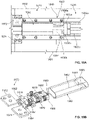
- Hinge 1970 can include an attachment mechanism to attach hinge 1970 to first and second chassis 1902 and 1904.
- the attachment mechanism can include a first hinge bracket 1972 configured for attachment to first chassis 1902 and a second hinge bracket 1974 figured for attachment to second chassis 1904.
- the attachment mechanism can be any suitable fastener, such as those previously described herein for example.
- a hinge cap 1960 may surround hinge elements connected to hinge brackets 1972 and 1974. The hinge elements can enable rotation of first chassis 1902 and/or second chassis 1904 relative to each other.
- a cable 1940 can be routed from first chassis 1902 through hinge cap 1960, to second chassis 1904. Cable 1940 can include a first cable portion 1942 extending from first chassis 1902 to hinge cap 1960, and a second cable portion 1944 extending from second chassis 1904 to hinge cap 1960.
- the middle portion of the heat carrying member and optionally, the middle FPC portion of the FPC can be fixedly secured to both rollers 1922a and 1922b of guide assembly 1920.
- a heat carrying member and/or an FPC may be fixedly secured to first and second rollers 1922a and 1922b in the same or similar manner as described with reference to heat carrying member 1210 and FPC 1240, for example.
- First roller 1922a can be rotatably coupled to first chassis 1902 by any suitable means to enable the first roller to have one degree of rotation (DOF) (i.e., rotational movement).
- Second roller 1922b can be rotatably coupled to second chassis 1904 by any suitable means to enable the second roller to have one degree of rotation (DOF) (i.e., rotational movement).
- DOF degree of rotation
- the rotational movement can be allowed by the rollers 1922a and 1922b to adjust for slack in the heat carrying member and/or the FPC.
- circular holes or projections may be configured to enable rotation.
- first roller 1922a can share a longitudinal axis with first shaft 1982
- second roller 1922b can share a longitudinal axis with second shaft 1984.
- First and second shafts 1982 and 1984 can be coupled by a first top bracket 1976, a second top bracket 1978, and torque rings 1979.
- Securing elements 1986 and 1988 may be provided at ends of first and second shafts 1982 and 1984.
- Second bracket 1978 may be attached to hinge cap 1960.
- another securing element 1989 may be provided to connect hinge cap 1960 to second frame 1978.
- the other securing element 1978 may include any suitable fastening mechanism as previously described here.
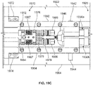
- FIG. 19C is a top plan view of hinge 1970 and one side of guide assembly 1920 according to one or more embodiments.
- hinge cap 1960 is removed to reveal hinge elements and a middle cable portion 1946 of cable 1940 that may be covered and protected by hinge cap 1960.
- Hinge cap 1960 may normally cover first and second shafts 1982 and 1984, torque elements 1987, first bracket 1976, second bracket 1978, torque rings 1979, securing elements 1986 and 1988, and a middle cable portion 1946 of cable 1940.
- FIG 19C also shows first bezel cover 1992 for first chassis 1902 and second bezel cover 1994 for second chassis 1904.
- Bezel covers 1992 and 1994 can cover inner edges of first and second chassis 1902 and 1904 adjacent to hinge 1970, including at least a portion of first and second hinge brackets 1972 and 1974.
- Hinge 1970 and a complementary hinge may be implemented in an electronic device with guide assembly 1920 in at least some embodiments.
- a flexible printed circuit e.g., 1240
- a heat carrying member e.g., 110, 1210, 1710 depending on the particular implementation and needs.
- cables, such as cable 1940 may be used instead of, or in addition to, an FPC.
- FIG. 20 shown is a block diagram of an example system 2000 in accordance with one or more embodiments of the present disclosure.
- Computing system 2000 is arranged in a point-to-point (PtP) configuration where processors, memory, and input/output devices are interconnected by a number of point-to-point interfaces.
- PtP point-to-point
- the computer architecture of one or more of the electronic devices (e.g., 110, 1210) described herein may be configured in the same or similar manner as computing system 2000.
- hinges and hinge assemblies e.g., 106, 1250
- guide units and guide assemblies e.g., 120, 1220
- Processors 2070 and 2080 may be implemented as single core processors 2074a and 2084a or multi-core processors 2074a-2074b and 2084a-2084b. Processors 2070 and 2080 may each include a cache 2071 and 2081 used by their respective core or cores. A shared cache (not shown) may be included in either processors or outside of both processors, yet connected with the processors via P-P interconnect, such that either or both processors' local cache information may be stored in the shared cache if a processor is placed into a low power mode. It should be noted that processors 2070 and 2080 are examples of the types of hardware that can be used in connection with the implementations shown and described herein, and may act as a heat source (e.g., 108, 1208) in one or more embodiments.
- a heat source e.g., 108, 1208
- Processors 2070 and 2080 may also each include integrated memory controller logic (IMC) 2072 and 2082 to communicate with memory elements 2032 and 2034.
- IMC integrated memory controller logic
- memory controller logic 2072 and 2082 may be discrete logic separate from processors 2070 and 2080.
- Memory elements 2032 and/or 2034 may store various data to be used by processors 2070 and 2080.
- Processors 2070 and 2080 may be any type of processor, based on particular implementations and needs.
- Processors 2070 and 2080 may exchange data via a point-to-point (PtP) interface 2050 using point-to-point interface circuits 2078 and 2088, respectively.
- Processors 2070 and 2080 may each exchange data with a chipset 2090 via individual point-to-point interfaces 2052 and 2054 using point-to-point interface circuits 2076, 2086, 2094, and 2098.
- Chipset 2090 may optionally exchange information with the coprocessor 2038 via a high-performance interface 2092.
- Chipset 2090 may be in communication with a bus 2010 via an interface circuit 2096.
- Bus 2010 may have one or more devices that communicate over it, such as a bus bridge 2018, I/O devices 2016, and potentially other processors 2015.
- bus bridge 2018 may be in communication with other devices such as a user interface 2012 (e.g., a keyboard, mouse, touchscreen, or other input devices), one or more sensors 2025, I/O devices 2026 (such as modems, network interface devices, or other types of communication devices that may communicate through a computer network 2060), audio I/O devices 2014, and/or a storage unit 2028.
- the system, apparatus, method, and machine readable medium embodiments can include one or a combination of the following examples:
- An Example Y1 provides an apparatus, the apparatus comprising means for performing the method of any one of the preceding Examples C1-C12 or G1-G4.
Landscapes
- Engineering & Computer Science (AREA)
- Theoretical Computer Science (AREA)
- Computer Hardware Design (AREA)
- Physics & Mathematics (AREA)
- Human Computer Interaction (AREA)
- General Engineering & Computer Science (AREA)
- General Physics & Mathematics (AREA)
- Mathematical Physics (AREA)
- Casings For Electric Apparatus (AREA)
- Cooling Or The Like Of Electrical Apparatus (AREA)
Applications Claiming Priority (1)
| Application Number | Priority Date | Filing Date | Title |
|---|---|---|---|
| US17/100,849 US12117876B2 (en) | 2020-11-21 | 2020-11-21 | Hinge assembly and guide assembly for electronic devices using a heat carrying member |
Publications (3)
| Publication Number | Publication Date |
|---|---|
| EP4002057A1 true EP4002057A1 (de) | 2022-05-25 |
| EP4002057C0 EP4002057C0 (de) | 2025-10-08 |
| EP4002057B1 EP4002057B1 (de) | 2025-10-08 |
Family
ID=75274844
Family Applications (1)
| Application Number | Title | Priority Date | Filing Date |
|---|---|---|---|
| EP21197807.7A Active EP4002057B1 (de) | 2020-11-21 | 2021-09-20 | Scharnieranordnung und führungsanordnung für elektronische vorrichtungen unter verwendung eines wärmeleitenden elements |
Country Status (4)
| Country | Link |
|---|---|
| US (1) | US12117876B2 (de) |
| EP (1) | EP4002057B1 (de) |
| CN (1) | CN114527833A (de) |
| PL (1) | PL4002057T3 (de) |
Families Citing this family (16)
| Publication number | Priority date | Publication date | Assignee | Title |
|---|---|---|---|---|
| KR102502607B1 (ko) * | 2017-11-14 | 2023-02-23 | 삼성전자주식회사 | 커넥터 모듈 및 이를 포함하는 전자 장치 |
| WO2019177622A1 (en) * | 2018-03-16 | 2019-09-19 | Hewlett-Packard Development Company, L.P. | Hinge assemblies |
| USD933060S1 (en) * | 2018-09-26 | 2021-10-12 | Intel Corporation | Convertible electronic device |
| CN109327586B (zh) * | 2018-10-31 | 2025-08-26 | 周金龙 | 一种穿戴式手机夹持装置 |
| WO2020230745A1 (ja) * | 2019-05-16 | 2020-11-19 | ソニー株式会社 | 熱伝導機構 |
| EP3993586B1 (de) * | 2019-06-28 | 2025-10-29 | LG Electronics Inc. | Avn-vorrichtung |
| US11599155B2 (en) * | 2020-04-21 | 2023-03-07 | Microsoft Technology Licensing, Llc | Hinged device |
| US12117876B2 (en) * | 2020-11-21 | 2024-10-15 | Intel Corporation | Hinge assembly and guide assembly for electronic devices using a heat carrying member |
| US11744045B2 (en) * | 2021-11-10 | 2023-08-29 | Qualcomm Incorporated | Electronic device comprising a thermally conductive connector comprising graphite |
| CN117616363A (zh) | 2021-12-16 | 2024-02-27 | 英特尔公司 | 多面板计算设备中的设备与处理器之间的消息转换和消息直通 |
| US12032171B1 (en) * | 2022-02-04 | 2024-07-09 | Meta Platforms Technologies, Llc | Thermal hinge system |
| US12393052B1 (en) | 2022-02-04 | 2025-08-19 | Meta Platforms Technologies, Llc | Systems and methods for controlling thermal energy between hinged portions of electronic devices |
| CN114709186B (zh) * | 2022-04-06 | 2024-11-29 | 甬矽电子(宁波)股份有限公司 | 基板和基板制作方法 |
| US20250264917A1 (en) * | 2023-01-09 | 2025-08-21 | Meta Platforms Technologies, Llc | Flexible hinge thermal architecture |
| JP7808778B2 (ja) * | 2023-02-06 | 2026-01-30 | パナソニックIpマネジメント株式会社 | 電子機器 |
| US12443244B2 (en) * | 2024-01-31 | 2025-10-14 | Dell Products L.P. | Information handling system assymetric display fold to support an adaptive keyboard row |
Citations (2)
| Publication number | Priority date | Publication date | Assignee | Title |
|---|---|---|---|---|
| US20190041922A1 (en) * | 2018-08-01 | 2019-02-07 | Intel Corporation | Thermal dissipation in dual-chassis devices |
| US20200120832A1 (en) * | 2019-12-13 | 2020-04-16 | Intel Corporation | Flexible hinge to accommodate a flexible heat spreader |
Family Cites Families (51)
| Publication number | Priority date | Publication date | Assignee | Title |
|---|---|---|---|---|
| FR2662304B1 (fr) | 1990-05-21 | 1992-07-24 | France Telecom | Procede de fabrication d'une structure integree guide-detecteur de lumiere en materiau semi-conducteur. |
| JPH08204373A (ja) | 1995-01-27 | 1996-08-09 | Diamond Electric Mfg Co Ltd | 放熱装置 |
| US5621613A (en) | 1995-05-16 | 1997-04-15 | Intel Corporation | Apparatus for dissipating heat in a hinged computing device |
| US5646822A (en) | 1995-08-30 | 1997-07-08 | Intel Corporation | Heat pipe exchanger system for cooling a hinged computing device |
| US5822187A (en) | 1996-10-25 | 1998-10-13 | Thermal Corp. | Heat pipes inserted into first and second parallel holes in a block for transferring heat between hinged devices |
| US5781409A (en) | 1996-12-19 | 1998-07-14 | Compaq Computer Corporation | Heat dissipating lid hinge structure with laterally offset heat pipe end portions |
| US5832987A (en) | 1997-03-21 | 1998-11-10 | Lowry; David A. | Rotatable heat transfer coupling |
| JPH10262719A (ja) | 1997-03-27 | 1998-10-06 | Mitsubishi Electric Corp | ノートパソコン収納ケース |
| US5796581A (en) | 1997-07-30 | 1998-08-18 | International Business Machines Corporation | Rotational joint for hinged heat pipe cooling of a computer |
| US5910883A (en) | 1997-08-06 | 1999-06-08 | International Business Machines Corporation | Hinge incorporating a helically coiled heat pipe for a laptop computer |
| US5847925A (en) | 1997-08-12 | 1998-12-08 | Compaq Computer Corporation | System and method for transferring heat between movable portions of a computer |
| JP3461269B2 (ja) | 1997-09-04 | 2003-10-27 | インターナショナル・ビジネス・マシーンズ・コーポレーション | 表示装置組立体及び情報処理機器 |
| US6075696A (en) | 1997-11-06 | 2000-06-13 | Compaq Computer Corporation | Portable computer with flexible heat spreader plate structure therein |
| JP2000010661A (ja) | 1998-06-18 | 2000-01-14 | Mitsubishi Electric Corp | 携帯型情報処理装置および携帯型情報処理装置用カバー、卓上型情報処理装置 |
| US6097597A (en) | 1998-06-30 | 2000-08-01 | Mitsubishi Denki Kabushiki Kaisha | Thermo-siphon and manufacturing method of thermo-siphon and information processing apparatus |
| US6353529B1 (en) | 1998-11-12 | 2002-03-05 | Thomas Cies | Z-configuration structure for computers, scanners, and communications and video devices |
| US6377452B1 (en) | 1998-12-18 | 2002-04-23 | Furukawa Electric Co., Ltd. | Heat pipe hinge structure for electronic device |
| US6052280A (en) | 1999-01-19 | 2000-04-18 | Alliedsignal Inc. | Carbon/carbon heat spreader |
| US6141216A (en) | 1999-03-31 | 2000-10-31 | International Business Machines Corporation | Quick-release hinge joint for heat pipe |
| US6253836B1 (en) | 1999-05-24 | 2001-07-03 | Compaq Computer Corporation | Flexible heat pipe structure and associated methods for dissipating heat in electronic apparatus |
| US6198625B1 (en) | 1999-06-03 | 2001-03-06 | Micron Electronics, Inc. | Hinge assembly for a portable computer |
| US6226177B1 (en) | 1999-06-08 | 2001-05-01 | Torqmaster, Inc. | Friction hinge having high thermal conductivity |
| US6249426B1 (en) | 1999-08-30 | 2001-06-19 | Dell Usa Corp | Portable computer having a sealed hinge clutch |
| US6512670B1 (en) | 2000-10-05 | 2003-01-28 | International Business Machines Corporation | Detachable displays or portable devices |
| US7236355B2 (en) | 2001-01-17 | 2007-06-26 | Boyean Kim | Sun visor having office work apparatus |
| US6741456B2 (en) | 2001-04-18 | 2004-05-25 | Hewlett-Packard Development Company, L.P. | System and method for pivotably securing display housing to computer system |
| JP3710780B2 (ja) | 2002-11-29 | 2005-10-26 | 京セラ株式会社 | コネクタ接続部構造及びこれを用いた携帯端末装置 |
| RU2395924C2 (ru) | 2003-07-10 | 2010-07-27 | Нокиа Корпорейшн | Мобильная станция |
| KR100760509B1 (ko) | 2004-12-14 | 2007-09-20 | 삼성전자주식회사 | 폴더 타입 휴대용 무선단말기의 방열 장치 |
| TW200725216A (en) | 2005-12-20 | 2007-07-01 | Asustek Comp Inc | Electronic device with a rotation positioning structure |
| JP2007286785A (ja) | 2006-04-14 | 2007-11-01 | Fujitsu Ltd | 電子機器および冷却部品 |
| JP2008305284A (ja) | 2007-06-11 | 2008-12-18 | Lenovo Singapore Pte Ltd | 携帯式コンピュータ |
| JP4888413B2 (ja) | 2008-02-14 | 2012-02-29 | 富士通株式会社 | 携帯型電子装置 |
| US8446264B2 (en) | 2010-07-21 | 2013-05-21 | Research In Motion Limited | Portable electronic device having a waterproof keypad |
| CN102858114A (zh) | 2011-06-28 | 2013-01-02 | 鸿富锦精密工业(深圳)有限公司 | 便携式电子装置 |
| TWM422001U (en) | 2011-07-13 | 2012-02-01 | Quanta Comp Inc | Dual-axis hinge structure and electric device having the same |
| US8675363B2 (en) | 2011-07-26 | 2014-03-18 | Hewlett-Packard Development Company, L.P. | Thermal conductors in electronic devices |
| US9766661B2 (en) | 2013-07-30 | 2017-09-19 | Intel Corporation | Stacking detachable tablet |
| US9490860B2 (en) | 2014-12-17 | 2016-11-08 | Asia Vital Components Co., Ltd. | Protective device capable of dissipating heat |
| EP3292458A4 (de) | 2015-05-05 | 2018-12-26 | Apple Inc. | Führung einer flexiblen leitung für einen dorn |
| US9980412B2 (en) | 2016-09-29 | 2018-05-22 | Intel Corporation | Flexible heat spreader |
| US10488898B2 (en) | 2017-03-31 | 2019-11-26 | Microsoft Technology Licensing, Llc | Flexible heat spreader |
| US10146278B2 (en) | 2017-03-31 | 2018-12-04 | Dell Products L. P. | Thermal spreader spanning two (or more) housings |
| US10120421B1 (en) | 2017-06-21 | 2018-11-06 | Dell Products L.P. | Flexible information handling system display |
| US10571977B2 (en) | 2017-12-26 | 2020-02-25 | Intel Corporation | Technologies for hinges for dual screen devices |
| US10936031B2 (en) | 2018-04-13 | 2021-03-02 | Dell Products L.P. | Information handling system dynamic thermal transfer control |
| US10579113B2 (en) | 2018-04-13 | 2020-03-03 | Dell Products L.P. | Graphite thermal conduit spring |
| US20200033911A1 (en) | 2018-07-27 | 2020-01-30 | George Moser | Laptop computer with multiple displays |
| US10254803B1 (en) | 2018-07-31 | 2019-04-09 | Dell Products, L.P. | Multi-form factor information handling system (IHS) with layered, foldable, bendable, flippable, rotatable, removable, displaceable, and/or slideable component(s) |
| US10976782B2 (en) | 2018-12-21 | 2021-04-13 | Intel Corporation | Offset hinge assembly for mobile compute devices |
| US12117876B2 (en) * | 2020-11-21 | 2024-10-15 | Intel Corporation | Hinge assembly and guide assembly for electronic devices using a heat carrying member |
-
2020
- 2020-11-21 US US17/100,849 patent/US12117876B2/en active Active
-
2021
- 2021-09-20 PL PL21197807.7T patent/PL4002057T3/pl unknown
- 2021-09-20 EP EP21197807.7A patent/EP4002057B1/de active Active
- 2021-10-21 CN CN202111228788.8A patent/CN114527833A/zh active Pending
Patent Citations (2)
| Publication number | Priority date | Publication date | Assignee | Title |
|---|---|---|---|---|
| US20190041922A1 (en) * | 2018-08-01 | 2019-02-07 | Intel Corporation | Thermal dissipation in dual-chassis devices |
| US20200120832A1 (en) * | 2019-12-13 | 2020-04-16 | Intel Corporation | Flexible hinge to accommodate a flexible heat spreader |
Also Published As
| Publication number | Publication date |
|---|---|
| CN114527833A (zh) | 2022-05-24 |
| US12117876B2 (en) | 2024-10-15 |
| US20210103317A1 (en) | 2021-04-08 |
| PL4002057T3 (pl) | 2026-01-26 |
| EP4002057C0 (de) | 2025-10-08 |
| EP4002057B1 (de) | 2025-10-08 |
Similar Documents
| Publication | Publication Date | Title |
|---|---|---|
| US12117876B2 (en) | Hinge assembly and guide assembly for electronic devices using a heat carrying member | |
| EP4207142B1 (de) | Faltbare vorrichtung und elektronische vorrichtung | |
| US8125759B2 (en) | Electronic apparatus | |
| US11723170B2 (en) | Electronic apparatus | |
| US11294431B2 (en) | Synchronized dual axis pivot hinge | |
| US11474570B2 (en) | Hinge structure for foldable device having flexible display panel | |
| US12069826B2 (en) | Flexible display panel and electronic device | |
| US20170188470A1 (en) | Display device | |
| EP4167051B1 (de) | Elektronisches gerät | |
| US10146268B2 (en) | Hinge apparatus, systems, and methods | |
| CN117119088B (zh) | 一种可折叠式移动终端 | |
| US12399540B2 (en) | Electronic apparatus | |
| US12386396B2 (en) | Electronic apparatus | |
| US12360573B2 (en) | Foldable electronic apparatus | |
| US12405637B2 (en) | Foldable device and display device | |
| CN112987851A (zh) | 用于适应柔性散热器的柔性铰链 | |
| JP6636125B1 (ja) | 携帯用情報機器 | |
| JP6532972B2 (ja) | 携帯用情報機器 | |
| JP2024179991A (ja) | 電子機器 | |
| JP6928153B2 (ja) | 携帯用情報機器 | |
| JP7731039B2 (ja) | 電子機器 | |
| CN119342722A (zh) | 壳体组件和可折叠电子设备 | |
| US11320872B2 (en) | Convertible electronic device | |
| KR20240175279A (ko) | 힌지 모듈 및 그를 포함하는 전자 장치 | |
| TW202121963A (zh) | 筆記型電腦 |
Legal Events
| Date | Code | Title | Description |
|---|---|---|---|
| PUAI | Public reference made under article 153(3) epc to a published international application that has entered the european phase |
Free format text: ORIGINAL CODE: 0009012 |
|
| STAA | Information on the status of an ep patent application or granted ep patent |
Free format text: STATUS: THE APPLICATION HAS BEEN PUBLISHED |
|
| AK | Designated contracting states |
Kind code of ref document: A1 Designated state(s): AL AT BE BG CH CY CZ DE DK EE ES FI FR GB GR HR HU IE IS IT LI LT LU LV MC MK MT NL NO PL PT RO RS SE SI SK SM TR |
|
| STAA | Information on the status of an ep patent application or granted ep patent |
Free format text: STATUS: REQUEST FOR EXAMINATION WAS MADE |
|
| 17P | Request for examination filed |
Effective date: 20221122 |
|
| RBV | Designated contracting states (corrected) |
Designated state(s): AL AT BE BG CH CY CZ DE DK EE ES FI FR GB GR HR HU IE IS IT LI LT LU LV MC MK MT NL NO PL PT RO RS SE SI SK SM TR |
|
| GRAP | Despatch of communication of intention to grant a patent |
Free format text: ORIGINAL CODE: EPIDOSNIGR1 |
|
| STAA | Information on the status of an ep patent application or granted ep patent |
Free format text: STATUS: GRANT OF PATENT IS INTENDED |
|
| RIC1 | Information provided on ipc code assigned before grant |
Ipc: G06F 1/20 20060101ALI20250417BHEP Ipc: G06F 1/16 20060101AFI20250417BHEP |
|
| INTG | Intention to grant announced |
Effective date: 20250507 |
|
| GRAS | Grant fee paid |
Free format text: ORIGINAL CODE: EPIDOSNIGR3 |
|
| GRAA | (expected) grant |
Free format text: ORIGINAL CODE: 0009210 |
|
| STAA | Information on the status of an ep patent application or granted ep patent |
Free format text: STATUS: THE PATENT HAS BEEN GRANTED |
|
| AK | Designated contracting states |
Kind code of ref document: B1 Designated state(s): AL AT BE BG CH CY CZ DE DK EE ES FI FR GB GR HR HU IE IS IT LI LT LU LV MC MK MT NL NO PL PT RO RS SE SI SK SM TR |
|
| REG | Reference to a national code |
Ref country code: GB Ref legal event code: FG4D Ref country code: CH Ref legal event code: F10 Free format text: ST27 STATUS EVENT CODE: U-0-0-F10-F00 (AS PROVIDED BY THE NATIONAL OFFICE) Effective date: 20251008 |
|
| REG | Reference to a national code |
Ref country code: DE Ref legal event code: R096 Ref document number: 602021039966 Country of ref document: DE |
|
| REG | Reference to a national code |
Ref country code: IE Ref legal event code: FG4D |
|
| U01 | Request for unitary effect filed |
Effective date: 20251103 |
|
| U07 | Unitary effect registered |
Designated state(s): AT BE BG DE DK EE FI FR IT LT LU LV MT NL PT RO SE SI Effective date: 20251106 |
|
| PG25 | Lapsed in a contracting state [announced via postgrant information from national office to epo] |
Ref country code: ES Free format text: LAPSE BECAUSE OF FAILURE TO SUBMIT A TRANSLATION OF THE DESCRIPTION OR TO PAY THE FEE WITHIN THE PRESCRIBED TIME-LIMIT Effective date: 20251008 |
|
| PG25 | Lapsed in a contracting state [announced via postgrant information from national office to epo] |
Ref country code: NO Free format text: LAPSE BECAUSE OF FAILURE TO SUBMIT A TRANSLATION OF THE DESCRIPTION OR TO PAY THE FEE WITHIN THE PRESCRIBED TIME-LIMIT Effective date: 20260108 |
|
| PG25 | Lapsed in a contracting state [announced via postgrant information from national office to epo] |
Ref country code: HR Free format text: LAPSE BECAUSE OF FAILURE TO SUBMIT A TRANSLATION OF THE DESCRIPTION OR TO PAY THE FEE WITHIN THE PRESCRIBED TIME-LIMIT Effective date: 20251008 |
|
| PG25 | Lapsed in a contracting state [announced via postgrant information from national office to epo] |
Ref country code: RS Free format text: LAPSE BECAUSE OF FAILURE TO SUBMIT A TRANSLATION OF THE DESCRIPTION OR TO PAY THE FEE WITHIN THE PRESCRIBED TIME-LIMIT Effective date: 20260108 |
|
| PG25 | Lapsed in a contracting state [announced via postgrant information from national office to epo] |
Ref country code: IS Free format text: LAPSE BECAUSE OF FAILURE TO SUBMIT A TRANSLATION OF THE DESCRIPTION OR TO PAY THE FEE WITHIN THE PRESCRIBED TIME-LIMIT Effective date: 20260208 |
|
| PG25 | Lapsed in a contracting state [announced via postgrant information from national office to epo] |
Ref country code: SM Free format text: LAPSE BECAUSE OF FAILURE TO SUBMIT A TRANSLATION OF THE DESCRIPTION OR TO PAY THE FEE WITHIN THE PRESCRIBED TIME-LIMIT Effective date: 20251008 |
|
| PG25 | Lapsed in a contracting state [announced via postgrant information from national office to epo] |
Ref country code: CZ Free format text: LAPSE BECAUSE OF FAILURE TO SUBMIT A TRANSLATION OF THE DESCRIPTION OR TO PAY THE FEE WITHIN THE PRESCRIBED TIME-LIMIT Effective date: 20251008 |
|
| PG25 | Lapsed in a contracting state [announced via postgrant information from national office to epo] |
Ref country code: SK Free format text: LAPSE BECAUSE OF FAILURE TO SUBMIT A TRANSLATION OF THE DESCRIPTION OR TO PAY THE FEE WITHIN THE PRESCRIBED TIME-LIMIT Effective date: 20251008 |
|
| PLBE | No opposition filed within time limit |
Free format text: ORIGINAL CODE: 0009261 |
|
| STAA | Information on the status of an ep patent application or granted ep patent |
Free format text: STATUS: NO OPPOSITION FILED WITHIN TIME LIMIT |