EP4002571A1 - Ein sicherheitsventil für eine batterie oder einen akkumulator für elektro- oder hybridfahrzeuge - Google Patents
Ein sicherheitsventil für eine batterie oder einen akkumulator für elektro- oder hybridfahrzeuge Download PDFInfo
- Publication number
- EP4002571A1 EP4002571A1 EP21196727.8A EP21196727A EP4002571A1 EP 4002571 A1 EP4002571 A1 EP 4002571A1 EP 21196727 A EP21196727 A EP 21196727A EP 4002571 A1 EP4002571 A1 EP 4002571A1
- Authority
- EP
- European Patent Office
- Prior art keywords
- housing
- valve
- battery
- spring
- valve element
- Prior art date
- Legal status (The legal status is an assumption and is not a legal conclusion. Google has not performed a legal analysis and makes no representation as to the accuracy of the status listed.)
- Pending
Links
- 238000007872 degassing Methods 0.000 claims abstract description 27
- 239000012528 membrane Substances 0.000 claims abstract description 20
- 238000009434 installation Methods 0.000 claims abstract description 6
- 238000004891 communication Methods 0.000 claims description 10
- 239000000463 material Substances 0.000 claims description 8
- 239000002184 metal Substances 0.000 claims description 7
- 230000002787 reinforcement Effects 0.000 claims description 6
- 238000005516 engineering process Methods 0.000 claims description 5
- 230000007613 environmental effect Effects 0.000 claims description 5
- 239000005028 tinplate Substances 0.000 claims description 5
- 238000005452 bending Methods 0.000 claims description 4
- 238000011109 contamination Methods 0.000 claims description 4
- 238000001746 injection moulding Methods 0.000 claims description 4
- XLYOFNOQVPJJNP-UHFFFAOYSA-N water Substances O XLYOFNOQVPJJNP-UHFFFAOYSA-N 0.000 claims description 4
- 230000005540 biological transmission Effects 0.000 claims description 3
- 239000002245 particle Substances 0.000 claims description 3
- 229910001220 stainless steel Inorganic materials 0.000 claims description 3
- 239000010935 stainless steel Substances 0.000 claims description 3
- 230000001133 acceleration Effects 0.000 claims description 2
- 239000002131 composite material Substances 0.000 claims description 2
- 239000004020 conductor Substances 0.000 claims description 2
- 238000001514 detection method Methods 0.000 claims description 2
- 238000007689 inspection Methods 0.000 claims description 2
- 230000003287 optical effect Effects 0.000 claims description 2
- 230000000704 physical effect Effects 0.000 claims description 2
- 230000005236 sound signal Effects 0.000 claims description 2
- 239000000126 substance Substances 0.000 claims description 2
- 239000012780 transparent material Substances 0.000 claims description 2
- 230000005294 ferromagnetic effect Effects 0.000 claims 1
- 239000007789 gas Substances 0.000 abstract description 6
- 238000007599 discharging Methods 0.000 abstract description 3
- 239000007788 liquid Substances 0.000 abstract description 2
- 239000000243 solution Substances 0.000 description 9
- 230000006835 compression Effects 0.000 description 4
- 238000007906 compression Methods 0.000 description 4
- 238000007789 sealing Methods 0.000 description 4
- 238000000034 method Methods 0.000 description 3
- 238000010276 construction Methods 0.000 description 2
- 230000003247 decreasing effect Effects 0.000 description 2
- 238000005474 detonation Methods 0.000 description 2
- 238000004880 explosion Methods 0.000 description 2
- 230000032683 aging Effects 0.000 description 1
- 230000009286 beneficial effect Effects 0.000 description 1
- 230000033228 biological regulation Effects 0.000 description 1
- 230000015572 biosynthetic process Effects 0.000 description 1
- 239000013043 chemical agent Substances 0.000 description 1
- 238000006243 chemical reaction Methods 0.000 description 1
- 238000006073 displacement reaction Methods 0.000 description 1
- 210000005069 ears Anatomy 0.000 description 1
- 230000000694 effects Effects 0.000 description 1
- 230000005611 electricity Effects 0.000 description 1
- 239000011888 foil Substances 0.000 description 1
- 229910001416 lithium ion Inorganic materials 0.000 description 1
- 230000007257 malfunction Effects 0.000 description 1
- 230000001681 protective effect Effects 0.000 description 1
- 239000007787 solid Substances 0.000 description 1
- 210000002105 tongue Anatomy 0.000 description 1
Images


Classifications
-
- H—ELECTRICITY
- H01—ELECTRIC ELEMENTS
- H01M—PROCESSES OR MEANS, e.g. BATTERIES, FOR THE DIRECT CONVERSION OF CHEMICAL ENERGY INTO ELECTRICAL ENERGY
- H01M50/00—Constructional details or processes of manufacture of the non-active parts of electrochemical cells other than fuel cells, e.g. hybrid cells
- H01M50/30—Arrangements for facilitating escape of gases
- H01M50/317—Re-sealable arrangements
- H01M50/325—Re-sealable arrangements comprising deformable valve members, e.g. elastic or flexible valve members
- H01M50/333—Spring-loaded vent valves
-
- H—ELECTRICITY
- H01—ELECTRIC ELEMENTS
- H01M—PROCESSES OR MEANS, e.g. BATTERIES, FOR THE DIRECT CONVERSION OF CHEMICAL ENERGY INTO ELECTRICAL ENERGY
- H01M50/00—Constructional details or processes of manufacture of the non-active parts of electrochemical cells other than fuel cells, e.g. hybrid cells
- H01M50/30—Arrangements for facilitating escape of gases
- H01M50/308—Detachable arrangements, e.g. detachable vent plugs or plug systems
-
- H—ELECTRICITY
- H01—ELECTRIC ELEMENTS
- H01M—PROCESSES OR MEANS, e.g. BATTERIES, FOR THE DIRECT CONVERSION OF CHEMICAL ENERGY INTO ELECTRICAL ENERGY
- H01M2220/00—Batteries for particular applications
- H01M2220/20—Batteries in motive systems, e.g. vehicle, ship, plane
-
- Y—GENERAL TAGGING OF NEW TECHNOLOGICAL DEVELOPMENTS; GENERAL TAGGING OF CROSS-SECTIONAL TECHNOLOGIES SPANNING OVER SEVERAL SECTIONS OF THE IPC; TECHNICAL SUBJECTS COVERED BY FORMER USPC CROSS-REFERENCE ART COLLECTIONS [XRACs] AND DIGESTS
- Y02—TECHNOLOGIES OR APPLICATIONS FOR MITIGATION OR ADAPTATION AGAINST CLIMATE CHANGE
- Y02E—REDUCTION OF GREENHOUSE GAS [GHG] EMISSIONS, RELATED TO ENERGY GENERATION, TRANSMISSION OR DISTRIBUTION
- Y02E60/00—Enabling technologies; Technologies with a potential or indirect contribution to GHG emissions mitigation
- Y02E60/10—Energy storage using batteries
Definitions
- the present invention belongs to the field of batteries, in particular to the field of constructional details of non-active parts such as housings, lids or deaeration systems for discharging gases from the interior of batteries.
- the invention relates to a safety pressure valve for installation on a housing of Li-ion or any other battery, which may be used in electric or hybrid vehicles, vessels or aircrafts.
- the technology of transportation means is striving to use electricity as the main energy source for powering vehicles, wherein energy is stored in a group of batteries, which are often installed inside a common housing that separates batteries from other vehicle parts and from the environment.
- the mentioned housing protects batteries from environmental effects and in case of malfunction or damage also protects the exterior (environment) against potentially dangerous chemical agents.
- limited space is available in the housing, said limited space usually being filled with air. The latter can be heated or cooled with regards to the elements, which results in increase or decrease of its volume. Consequently, a pressure difference may be created in the housing, possibly damaging it.
- housings are provided with a suitable valve or a degassing unit.
- valves allow such function, but show some disadvantages.
- some solutions require puncturing of a membrane, the whole disc or a foil, or use polymeric materials, which are not desired due to possible problems connected with temperature dependence of mechanical properties and ageing.
- Some known solutions should be dimensionally adjusted, due to their limited surfaces for degassing, which would lead to larger, thicker or more expensive valves.
- the technical problem which is solved by the present invention, is construction of a safety valve that will ensure simple and reliable discharge of gasses in urgent cases, while the valve will ensure reliable sealing in conditions at normal operation.
- Patent DE102012022346 describes a housing for a battery or an accumulator of an electric or a hybrid vehicle, wherein the housing has an interior and an opening, a membrane and a membrane carrier, wherein the membrane carrier represents the central part of the housing, which has a carrier body with an interior and exterior as well as an opening between the interior and exterior, which is covered with the membrane and a membrane covering.
- the membrane is on the other side protected with a protective element; wherein multiple grid openings are arranged between support grid nets in the form of gas passage apertures for degassing of the housing interior. All said parts are water-tightly connected with each other, whereas only air can pass due said parts to air discharge or pressure regulation.
- Patent application WO2020164902 relates to a pressure-relief valve for reducing pressure arising in a cell-like cavity, such as a battery cell, comprising a cover, which supports a seal for sealing a housing opening up to a predefined cell pressure and a holding device in order to fix the cover to the housing aperture.
- the holding device has a spring clamp, which is symmetrically shaped with six evenly distributed spring tongues extending radially from the central part. The spring clamp is pressed onto the housing aperture and during installation of the valve into the battery cell the spring can pass the edge of the aperture in the direction of assembling and is stuck in place in the radial direction.
- the present invention differs from this solution in the shape and the position of the spring.
- a complete opening of the housing aperture by ejecting the valve core, which is one of the key functions of the present invention, is not enabled with the solution according to WO2020164902 .
- Document JP2012195217 describes a safety valve for a battery, which has a seal for contacting an opening of housing of the battery, a central plate in contact with the seal and a leaf spring for pushing the seal against the opening.
- the valve has some additional parts and side parts, which affect the state of the central plate.
- pressure acting on the seal is equal to or smaller than a predetermined pressure
- the seal closes the opening.
- the pressure acting on the seal exceeds the predetermined pressure
- the first part of the side plate is rotated with respect to the first supporting part and the second side plate is rotated with regards to the second supporting part, which causes a movement of the centre plate away from the opening, causing displacement of the in the direction away from the opening.
- JP2012195217 does not mention a function of permanent open status of the housing opening, which represents a major difference with regards to the present invention.
- the valve described in patent JP2012195218 uses a leaf spring, which pushes onto the seal, when the pressure is lower than the pre-set value. Once the pressure is increased, the spring is separated from the seal and the opening of degassing is opened.
- the concept described in JP2012195218 does not allow full open status of the housing opening, as the welded spring element, which covers the housing opening from the exterior, only deforms, but stays in the same place.
- Document CN209434271 describes a valve having a different construction as the present invention, while it uses a compression spring for ensuring the push force of the valve onto the battery housing, which significantly differs from the present invention.
- the present invention solves the disadvantages of known solutions, wherein the main problem of triggering emergency degassing is solved with a specially shaped and specifically fastened spring element.
- This specific fastening manner allows removal of the central part of the valve upon triggering of emergency degassing, and at the same time also allows placement of an air-permeable waterproof membrane onto the removable central part of the valve, which is a highly valuable additional function. More precisely, by increasing deformation, the spring element slides from one of the supporting elements, thus unlocking itself from the support and releasing the central part of the valve for ejection, while at the same time the position of the spring element does not hinder membrane function, because it is in its basic position attached to the frame of the central part of the valve and on the valve housing at points, which allows passage of gas through the membrane.
- valve element The central part of the valve is in the continuation of the description termed as valve element, which may comprise several parts.
- the spring and similar elastic elements are in known solutions used for compression of seals onto the opening of the battery housing during normal operation.
- all solutions with a spring are permanently connected and the valve or its area for degassing is not fully opened, while the valve is returned to its basic position once degassing and pressure equalization is completed.
- An exception is patent CN201681989U , where a coil spring is installed between the valve element and a detonation lid of the housing, which is an additional spring element between the housing and the valve element, while its position is between the valve element and the exterior (i.e., outside). Because the detonation lid seals the space between the valve element and the environment, it prevents installation of an air permeable membrane on the valve element. The spring on the outside also means that dirt could prevent valve function. Therefore, this known solution differs from the present invention.
- the spring element in the present invention as an individual component ensures:
- the reason for removal of the central part of the valve is the need for decreasing pressure inside the battery housing once emergency degassing has already been initiated. In addition to gas, hard particles are also removed from the housing in the continuation of the process, therefore the opening should remain fully opened.
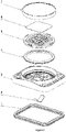
- the safety valve according to the invention comprises at least the following components:
- the spring element is installed between the housing and the frame of the valve element and is shaped as a symmetric or asymmetric leaf spring, which presses onto the housing on the surface facing towards the battery housing interior as well as onto the valve element on a surface facing the battery housing exterior.
- the said spring element is symmetrically shaped, wherein from its middle part two legs project in opposite direction, each of said legs ending with ends that are approximately perpendicularly bent with regards to longer parts of both legs.
- One leg of the spring would also be sufficient for operation, only suitable geometry of leading and spring mounting is necessary for suitably connect the leg with elements of the housing or the valve element, respectively.
- the middle part may be equipped with attachment or positioning elements, which prevent movement of the spring left or right, respectively.
- the spring element may be made from metal, preferably from stainless steel. It could also be made from a different suitable material or a composite structure from different materials. The material has to exhibit high resistance to environmental conditions, while it is also beneficial if it can be mass produced.
- the spring element has two positions - the basic position in normal operation and a final position in case of an increased pressure in the battery or the housing where batteries are installed.
- the spring In the basic position the spring is placed so that it has a sliding connection at least with the housing or the valve element or a part thereof. This connection is directed so that the spring allows compression of the seal between the housing and the valve element or its opening in the frame.
- Said sliding connection in usual (normal) conditions of operation ensures connection between the housing and the valve unit.
- more spring elements may be used, said spring elements being installed on several places between the housing and the valve element or its frame.
- the contacts in which forces for sliding contacts act, may be transferred from the central part of the hole in the valve frame towards the sealing edge between the valve element and the valve housing, thereby decreasing the need for increased rigidity of the housing and/or the valve element. This allows saving in the used material and/or in the height of the valve frame and/or the valve housing.
- the housing of the valve may be shaped as a low rectangular solid having a central opening, which is at its edge provided with a concluded seat for the sealing element between the housing and the valve element. From the concluded shape around the opening grid forming console connections or crossbars are provided.
- the membrane may be any suitable filter, which is impermeable to water, but permeable for air. On the edges of the opening it is fused with the frame of the valve element or it can be pressed to the frame of the valve element with an additional element.
- the membrane may be installed between the valve frame and the lid or on the valve frame adjacent to the valve element, which may be ejected with the help of the spring element.
- the lid of the valve element is shaped as a plate, which delimits the environment and the space above the membrane, but does not seal the space above the membrane from the environment.
- the seal may be at least one or more, any suitable seal may be used.
- the seal is made from a material having lower rigidity as the housing.
- the seal is installed between the valve housing and the frame of the valve element and may be produced as a single independent component or it may be produced with a technology of sequential injection moulding of several components. In the latter case the seal is a soft component on the basic frame or a soft component on the element, which fulfils the function of the frame of the valve element.
- the seal may be either glued or injected on the housing or the valve frame using 2K injection moulding technology. Although one seal is sufficient, more consecutive seals in a sandwich formation may be used.
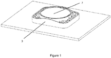
- the valve element which is removably connected with the valve housing 3, may comprise several parts and preferably comprises a frame 5 of the valve element.
- the frame 5 of the valve element may be provided with a through-hole in its central part.
- the valve element may further comprise a lid 7 for protection against environmental conditions, which forms a closed space with the frame 5 of the valve element, said closed space not being sealed against the environment nor against the central hole in the frame 5 of the valve element, wherein the central hole in the frame 5 of the valve element is closed against water ingress with an air permeable membrane 6.
- the safety valve may have other optional components selected in the group comprising the components such as:
- the safety valve according to the invention is installed on the housing of batteries for use in vehicles in known manners.
- the invention is suitable for all batteries and accumulators of electric and hybrid vehicles.
- the safety valve according to the embodiment shown in figures 1 to 3 comprises the following components:
- the spring element 2 is installed between the housing 3 and the frame 5 of the valve element, and is shaped as a leaf spring as shown in figure 6 .
- Said spring 2 is symmetrically shaped, namely, from the central part 2a two pairs of protrusions 2a' continue in opposite directions into two legs 2b, of which short parts on far ends 2b" are bent at approximately right angle towards long parts 2b'.
- the valve element may have a covering (lid) 7 for protection against environmental conditions, said covering forming a closed space with the frame 5 of the valve element, which is not sealed against the exterior nor towards the central opening in the frame 5 of the valve element.
- the central part in the frame 5 of the valve element may be closed against water ingress with an air permeable membrane 6.
- the valve unit (assembly of elements 5, 6, 7) is connected to the housing 3 with at least one pre-tensed leaf-shaped spring element 2, preferably made from metal/stainless steel, which ensures an assembly force between the housing 3 and the valve unit.
- the spring element 2 translates the needed force for compression of the seal 4 directly from the housing 3 to the frame 5 of the valve element so that it lays on at least one (straight or inclined) towards the battery housing exterior directed locking surface of the frame 5 of the valve element.
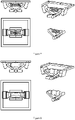
- Figure 4 shows a view of the safety valve with marked basic position of the spring element, wherein the physical sliding contact between the spring element 2 and the frame 5 of the valve element is visible.
- the spring element 2 is supported with housing 3 geometry, which limits movement of the spring element 2 in the direction of the axis towards the battery housing exterior as shown in figure 4 .
- the process of emergency degassing is an event when the pressure P i inside the housing 3 increases to a pre-defined and spring dimension-defined value for triggering of the mechanism for emergency degassing as shown in figure 5 .
- the effect of pressure on the inner surfaces of the valve element causes an increase of forces F v/sp and R H/sp , which act on the spring element 2, and consequently cause a bending deformation of the spring element 2 and relative movement of the valve unit with regards to the housing 3 in the axis direction towards the exterior of the battery housing (direction of axis and the exterior of the battery housing is shown in figure 5 ).
- the spring element 2 due to its shape and mounting enables that in case of emergency degassing at least one of the parts in contact with the spring element 2 loses the sliding contact (loss of at least one pair of the counteracting locking forces F sp/v and F v/sp shown in figure 5 ) between the spring element and a surface, which consequently results in full loss of joining forces (F sp/v ,F v/sp , R H/sp , F sp/H shown in figure 5 ) between the valve element and the valve housing 3.
- This allows ejection of the valve element due to the pressure inside the battery housing, thus completing the process of triggering of the emergency degassing.
- the triggering pressure P i inside the battery housing can consequently cause ejection of the valve unit 5, 6, 7 from the hole in housing 3.
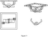
- Figures 7, 8 , 9, 10 and 11 show alternative embodiments of the spring element, namely figures 7, 8 , 9 and 10 as a hinge with a spring, rubber spring, two oppositely oriented magnets or a magnet and a tinplate, wherein the spring or the force between the magnets or the magnet and the tinplate holds both legs of the hinge in the required position, said hinge legs being in the same sliding contacts as the spring element according to figure 6 and show the same shape deformation upon pressure change.
- FIG 11 shows a coil spring mounted in a bent manner, said spring also having two legs, which ensure a connecting (assembly) force between the valve frame 3 and the valve unit.
- the mounted coil spring has a physical sliding contact with the frame 5 of the valve element and is supported with the geometry of the housing 3, which delimits its movement in the axis towards the exterior of the battery housing as is also shown in figure 4 for the embodiment of the spring element according to figure 6 .
- Figures 7 , 8 , 9 , 10 and 11 show alternative embodiments of the spring element, wherein the left side of figures represent possible contact geometric elements of the housing and the valve frame, while the right side of the figures 7, 8 , 9, 10 and 11 shows an isometric view of individual alternative embodiments with marked possible contact geometry elements (above) and individual assembly of the spring element in figures 7 and 8 (below), assembly of the spring element with two oppositely oriented magnets in figure 9 , the assembly of spring element with a scissor transmission of forces with the magnet and the tin plate in figure 10 , and individual spring element in figure 11 .
Landscapes
- Chemical & Material Sciences (AREA)
- Chemical Kinetics & Catalysis (AREA)
- Electrochemistry (AREA)
- General Chemical & Material Sciences (AREA)
- Gas Exhaust Devices For Batteries (AREA)
Applications Claiming Priority (1)
| Application Number | Priority Date | Filing Date | Title |
|---|---|---|---|
| SI202000206A SI26109A (sl) | 2020-11-11 | 2020-11-11 | Varnostni ventil za baterijo ali akumulator za električna ali hibridna vozila |
Publications (1)
| Publication Number | Publication Date |
|---|---|
| EP4002571A1 true EP4002571A1 (de) | 2022-05-25 |
Family
ID=78528581
Family Applications (1)
| Application Number | Title | Priority Date | Filing Date |
|---|---|---|---|
| EP21196727.8A Pending EP4002571A1 (de) | 2020-11-11 | 2021-09-14 | Ein sicherheitsventil für eine batterie oder einen akkumulator für elektro- oder hybridfahrzeuge |
Country Status (2)
| Country | Link |
|---|---|
| EP (1) | EP4002571A1 (de) |
| SI (1) | SI26109A (de) |
Cited By (4)
| Publication number | Priority date | Publication date | Assignee | Title |
|---|---|---|---|---|
| DE102022109076A1 (de) | 2022-04-13 | 2023-10-19 | Man Truck & Bus Se | Ventilmontage an ein Gehäuse eines elektrischen Energiespeichers |
| EP4421944A3 (de) * | 2023-02-01 | 2024-10-16 | MANN+HUMMEL Ventures Pte. Ltd. | Warnsystem, entgasungseinheit für ein elektronisches gehäuse und elektronisches gehäuse mit entgasungseinheit |
| EP4546537A1 (de) * | 2023-10-23 | 2025-04-30 | Automotive Cells Company SE | Energiespeicherzelle mit stützelement für die entlüftungsmembran |
| EP4589750A1 (de) * | 2024-01-22 | 2025-07-23 | MANN+HUMMEL GmbH | Entlüftungseinheit und batterie mit entlüftungseinheit |
Citations (9)
| Publication number | Priority date | Publication date | Assignee | Title |
|---|---|---|---|---|
| CN201681989U (zh) | 2010-08-20 | 2010-12-22 | 王文林 | 动力锂电池安全阀 |
| JP2012195218A (ja) | 2011-03-17 | 2012-10-11 | Chuo Spring Co Ltd | 安全弁及び安全弁を備えた電池 |
| JP2012195217A (ja) | 2011-03-17 | 2012-10-11 | Chuo Spring Co Ltd | 安全弁及び安全弁を備えた電池 |
| DE102012022346A1 (de) | 2012-11-15 | 2014-05-15 | Mann+Hummel Gmbh | Batterie-Gehäuse |
| US20160036025A1 (en) * | 2014-08-04 | 2016-02-04 | Lisa Draexlmaier Gmbh | Degassing valve |
| CN109980153A (zh) * | 2017-12-28 | 2019-07-05 | 广州倬粤动力新能源有限公司 | 一种环保碳金水平电池泄气阀结构 |
| CN209434271U (zh) | 2018-12-07 | 2019-09-24 | 东莞蒲微防水透气膜材料有限公司 | 一种用于新能源汽车动力电池包的防爆泄压安全阀 |
| WO2020141044A1 (de) * | 2019-01-04 | 2020-07-09 | Mann+Hummel Gmbh | Entgasungseinheit und elektronikgehäuse, insbesondere batteriegehäuse |
| WO2020164902A1 (de) | 2019-02-12 | 2020-08-20 | Hugo Benzing Gmbh & Co Kg | Druckentlastungsventil zum abbau von in einem zellenartigen hohlraum, wie einer batteriezelle, entstehendem druck |
-
2020
- 2020-11-11 SI SI202000206A patent/SI26109A/sl active IP Right Grant
-
2021
- 2021-09-14 EP EP21196727.8A patent/EP4002571A1/de active Pending
Patent Citations (9)
| Publication number | Priority date | Publication date | Assignee | Title |
|---|---|---|---|---|
| CN201681989U (zh) | 2010-08-20 | 2010-12-22 | 王文林 | 动力锂电池安全阀 |
| JP2012195218A (ja) | 2011-03-17 | 2012-10-11 | Chuo Spring Co Ltd | 安全弁及び安全弁を備えた電池 |
| JP2012195217A (ja) | 2011-03-17 | 2012-10-11 | Chuo Spring Co Ltd | 安全弁及び安全弁を備えた電池 |
| DE102012022346A1 (de) | 2012-11-15 | 2014-05-15 | Mann+Hummel Gmbh | Batterie-Gehäuse |
| US20160036025A1 (en) * | 2014-08-04 | 2016-02-04 | Lisa Draexlmaier Gmbh | Degassing valve |
| CN109980153A (zh) * | 2017-12-28 | 2019-07-05 | 广州倬粤动力新能源有限公司 | 一种环保碳金水平电池泄气阀结构 |
| CN209434271U (zh) | 2018-12-07 | 2019-09-24 | 东莞蒲微防水透气膜材料有限公司 | 一种用于新能源汽车动力电池包的防爆泄压安全阀 |
| WO2020141044A1 (de) * | 2019-01-04 | 2020-07-09 | Mann+Hummel Gmbh | Entgasungseinheit und elektronikgehäuse, insbesondere batteriegehäuse |
| WO2020164902A1 (de) | 2019-02-12 | 2020-08-20 | Hugo Benzing Gmbh & Co Kg | Druckentlastungsventil zum abbau von in einem zellenartigen hohlraum, wie einer batteriezelle, entstehendem druck |
Cited By (5)
| Publication number | Priority date | Publication date | Assignee | Title |
|---|---|---|---|---|
| DE102022109076A1 (de) | 2022-04-13 | 2023-10-19 | Man Truck & Bus Se | Ventilmontage an ein Gehäuse eines elektrischen Energiespeichers |
| EP4421944A3 (de) * | 2023-02-01 | 2024-10-16 | MANN+HUMMEL Ventures Pte. Ltd. | Warnsystem, entgasungseinheit für ein elektronisches gehäuse und elektronisches gehäuse mit entgasungseinheit |
| US12225672B2 (en) | 2023-02-01 | 2025-02-11 | Mann+Hummel Ventures Pte. Ltd. | Alert system, degassing unit for an electronic housing, and electronic housing comprising degassing unit |
| EP4546537A1 (de) * | 2023-10-23 | 2025-04-30 | Automotive Cells Company SE | Energiespeicherzelle mit stützelement für die entlüftungsmembran |
| EP4589750A1 (de) * | 2024-01-22 | 2025-07-23 | MANN+HUMMEL GmbH | Entlüftungseinheit und batterie mit entlüftungseinheit |
Also Published As
| Publication number | Publication date |
|---|---|
| SI26109A (sl) | 2022-05-31 |
Similar Documents
| Publication | Publication Date | Title |
|---|---|---|
| EP4002571A1 (de) | Ein sicherheitsventil für eine batterie oder einen akkumulator für elektro- oder hybridfahrzeuge | |
| CN110088933B (zh) | 用于牵引电池的电池单元和牵引电池 | |
| EP3477756B1 (de) | Lüftungsvorrichtung für eine batterie | |
| KR102774282B1 (ko) | 일체형 필터 메쉬를 벤팅홀에 적용한 팩 하우징 및 이를 포함하는 배터리 팩 | |
| US10164227B2 (en) | Degassing valve | |
| CN113228391A (zh) | 除气单元、电子装置壳体、尤其是电池壳体以及机动车 | |
| US20120107650A1 (en) | Magnetic sealing valve device for a battery case | |
| US20220352594A1 (en) | Battery vent system | |
| EP1978589A1 (de) | Batteriepack | |
| EP3739664A1 (de) | Sicherheitsventil für elektrochemische vorrichtungsgehäuse | |
| CN112610738A (zh) | 防爆阀 | |
| CN114846690A (zh) | 具有阀装置的电池壳体、电池以及机动车 | |
| CN114080712A (zh) | 采用力感测电阻器(fsr)压力传感器的汽车牵引电池的热失控检测 | |
| CN115602992A (zh) | 脱气单元和壳体、尤其是电池壳体 | |
| EP2581961A1 (de) | Sekundärbatterie | |
| CN108258165B (zh) | 电池箱、电池箱制造方法及电池系统 | |
| JP5476470B2 (ja) | 加圧保護を備えるガルバニ電池 | |
| US20250174822A1 (en) | Venting unit for venting machinery space | |
| CN121663090A (zh) | 用于电池外壳通气的折叠隔膜载体 | |
| JP2020107552A (ja) | 蓄電装置 | |
| CN113904057A (zh) | 泄压阀、电池块、电池模组及蓄电池 | |
| CN219734327U (zh) | 一种新型的塑胶材质泄压防爆平衡阀 | |
| CN109560219B (zh) | 蓄电组件 | |
| EP3739665A1 (de) | Sicherheitsventil mit ablösungsfunktion | |
| JP7852809B2 (ja) | バッテリパック |
Legal Events
| Date | Code | Title | Description |
|---|---|---|---|
| PUAI | Public reference made under article 153(3) epc to a published international application that has entered the european phase |
Free format text: ORIGINAL CODE: 0009012 |
|
| STAA | Information on the status of an ep patent application or granted ep patent |
Free format text: STATUS: THE APPLICATION HAS BEEN PUBLISHED |
|
| AK | Designated contracting states |
Kind code of ref document: A1 Designated state(s): AL AT BE BG CH CY CZ DE DK EE ES FI FR GB GR HR HU IE IS IT LI LT LU LV MC MK MT NL NO PL PT RO RS SE SI SK SM TR |
|
| STAA | Information on the status of an ep patent application or granted ep patent |
Free format text: STATUS: REQUEST FOR EXAMINATION WAS MADE |
|
| 17P | Request for examination filed |
Effective date: 20221118 |
|
| RBV | Designated contracting states (corrected) |
Designated state(s): AL AT BE BG CH CY CZ DE DK EE ES FI FR GB GR HR HU IE IS IT LI LT LU LV MC MK MT NL NO PL PT RO RS SE SI SK SM TR |
|
| P01 | Opt-out of the competence of the unified patent court (upc) registered |
Effective date: 20230523 |
|
| STAA | Information on the status of an ep patent application or granted ep patent |
Free format text: STATUS: EXAMINATION IS IN PROGRESS |
|
| 17Q | First examination report despatched |
Effective date: 20240702 |