EP4002618B1 - Unterflurinstallationsdose - Google Patents
Unterflurinstallationsdose Download PDFInfo
- Publication number
- EP4002618B1 EP4002618B1 EP21208901.5A EP21208901A EP4002618B1 EP 4002618 B1 EP4002618 B1 EP 4002618B1 EP 21208901 A EP21208901 A EP 21208901A EP 4002618 B1 EP4002618 B1 EP 4002618B1
- Authority
- EP
- European Patent Office
- Prior art keywords
- cord outlet
- cover
- installation box
- closure body
- outlet opening
- Prior art date
- Legal status (The legal status is an assumption and is not a legal conclusion. Google has not performed a legal analysis and makes no representation as to the accuracy of the status listed.)
- Active
Links
Images

Classifications
-
- H—ELECTRICITY
- H02—GENERATION; CONVERSION OR DISTRIBUTION OF ELECTRIC POWER
- H02G—INSTALLATION OF ELECTRIC CABLES OR LINES, OR OF COMBINED OPTICAL AND ELECTRIC CABLES OR LINES
- H02G3/00—Installations of electric cables or lines or protective tubing therefor in or on buildings, equivalent structures or vehicles
- H02G3/02—Details
- H02G3/08—Distribution boxes; Connection or junction boxes
- H02G3/18—Distribution boxes; Connection or junction boxes providing line outlets
- H02G3/185—Floor outlets and access cups
-
- H—ELECTRICITY
- H02—GENERATION; CONVERSION OR DISTRIBUTION OF ELECTRIC POWER
- H02G—INSTALLATION OF ELECTRIC CABLES OR LINES, OR OF COMBINED OPTICAL AND ELECTRIC CABLES OR LINES
- H02G3/00—Installations of electric cables or lines or protective tubing therefor in or on buildings, equivalent structures or vehicles
- H02G3/02—Details
- H02G3/08—Distribution boxes; Connection or junction boxes
- H02G3/14—Fastening of cover or lid to box
Definitions
- the invention relates to a cover for an underfloor installation box for accommodating electrical/electronic installations, which cover has a cord outlet, the cord outlet opening of which can be closed when not in use by a closure element and when in use at least partially with a flexible cord outlet filling that allows one or more lines to pass through.
- Installation boxes for electrical/electronic installations are required for underfloor installation.
- Such an underfloor installation can involve installing the installation box in a hollow floor or in a screed.
- Installation boxes with a cover having a cord outlet are arranged at those positions of a cable duct system in which the installation box is switched on, where access to electrical/electronic installations is required, for example access to sockets for powering electrical devices or also connection boxes of a data communication network .
- Installation boxes of this type often have an adjustable cord outlet, through which the cord outlet opening of the lid is closed if no cable is to be led out of the installation box. In the other position, the cord outlet is swiveled or raised relative to the upper end of the lid, so that lines or cables can then be led out of or into the installation box through the cord outlet opening provided.
- an installation box for an underfloor installation in which a closure element is pivotally articulated on the lid side in order to be pivoted from its use position, when it closes the cord outlet opening of the lid, into a non-use position towards the inside of the lid. Then the cord outlet opening of the lid is not closed.
- the lid When the lid is closed, there is a flexible one underneath it, aligned with its cord outlet opening, on the frame of the installation box
- Cord outlet filling which can be designed as a brush strip, for example. The cord outlet opening is closed by the bristles on the brush strip.
- a cable to be led out of the installation box passes through the flexible bristles of the row of brushes, which nestle against the cable that is led out, so that the remaining cord outlet opening is closed against the ingress of dust or other contaminants into the installation box.
- the advantage of this installation box is that even when the cable is led out of the installation box, no fixed cover components protrude from the top of the cover, thus avoiding the risk of tripping.
- positioning of the cover on the installation box or its frame is only possible in a single position, since the cord outlet opening must be arranged on that side of the installation box or its frame on which the flexible cord outlet filling held on the installation box side is located. In this respect, it is necessary that the cover and the installation box are coordinated not only in terms of their dimensions.
- KR 2018 0129402 A reveals an underfloor installation box.
- the installation box there is a support structure with a tubular elastic element projecting from it towards a cover.
- a cover is connected to this, which is circumferentially mounted on a flange Frame part sits on. Due to the connection to the elastic element, it can be rotated in the circumferential direction.
- the top of the frame member is mounted flush with the adjacent surface of a floor.
- a closure body is assigned to each cord outlet opening.
- the closure body has a closure element and a lace outlet hood.
- Such a closure body can be mounted on the cover either in a position for closing the cord outlet opening or for letting out a cable with its cord outlet hood in the cord outlet opening.
- the closure element is located in the cord outlet opening.
- the cord outlet hood is located above the cord outlet opening. The cord outlet hood protrudes from the top of the cover and is used for cable routing so that a cable leading out of it is guided away from the underfloor installation box in the radial direction.
- US 4,688,491A reveals a cord outlet on the surface of a work table.
- This cord outlet has a lid with a cord outlet opening that can be closed when not in use with a closure element that can be moved relative to the lid.
- the invention is therefore based on the object of proposing an underfloor installation box that is more flexible in terms of its possible uses.
- the lid of this underfloor installation box has a locking body.
- the closure body includes the closure element and the flexible cord outlet filling.
- the closure element for closing the cord outlet opening which is typically arranged at the edge of the lid, and the flexible cord outlet filling are arranged relative to one another in such a way that the closure body can be arranged either with its closure element or its flexible cord outlet filling in the cord outlet opening of the lid.
- the closure body can therefore be held on the lid in two different positions. If no line outlet is desired, the closure body is arranged on the lid so that its closure element closes the cord outlet opening. In a second position of the closure body on the lid, the flexible cord outlet filling is arranged in the cord outlet opening of the closure body.
- such a closure body can be arranged in two different positions of use with respect to filling the cord outlet opening on the cover part.
- the closure body can be held on the lid so that it can pivot about a vertical axis, for example, in order to arrange the closure element or the flexible cord outlet filling within the cord outlet opening depending on the desired use, it is provided that the closure body is a part that can be detached from the lid is. This can then be mounted on the lid depending on the desired type of use, namely either that its closure element or its flexible cord outlet filling is to be arranged within the cord outlet opening of the lid. The spatial position of the closure body is selected accordingly when it is mounted on the lid. It is intended that for the assembly of the closure body on the lid, the lid has two guide slots on the inside, into which the closure body is inserted and in which it is held.
- the closure body has appropriate guide strips, which engage in the guide slots on the lid side to hold the closure body on the lid.
- the guide strips can be pulled out of the guide slots so that the closure body can be inserted into the guide slot with its guide strips in the orientation intended for the desired use.
- the closure body Since the closure body is arranged on the cover of the installation box, it can be arranged in any orientation to the actual installation box or its frame. This allows the cord outlet side to be changed even after the installation box has already been installed. Since the cord outlet of this lid with the two elements - closure element and flexible cord outlet filling - can be closed solely with the closure body held on the lid side, this lid can be connected to any installation boxes or their frame parts or used to close them.
- the installation box therefore does not need to have any special design features so that its installation opening can be closed as intended with a cover of the type described above. As a result, the variety of applications of the cover part according to the invention is not insignificantly improved.
- each of the two elements carries two such guide strips.
- the desired element with its guide strips can be inserted into the guide slots on the cover side and thus positioned to close the cord outlet opening.
- the element that is not used in an application is then located on the inside of the cover adjacent to the cord outlet opening.
- Arranging the two elements in two levels allows the use of a lid with a recess on the top for inserting a design element, for example a metal plate, a carpet tile or another type of floor covering, such as that laid adjacent to the installation box.
- a design element for example a metal plate, a carpet tile or another type of floor covering, such as that laid adjacent to the installation box.
- the two elements of the closure body do not need to be arranged in two different planes.
- the closure element itself can be a plate-like element which rests on the inside of the lid, spanning the cord outlet opening.
- the closure element carries a filler piece which engages in the cord outlet opening and fills it. This can also be a floor covering section.
- the closure body is preferably fixed on the lid side in its position of use.
- the fixation is advisable to design the fixation as a snap-in fixation.
- Such a fixation also provides a user with haptic feedback when the closure body is in the respective position of use.
- these can be used to form a locking cam on at least one of these guide strips. When the use position is reached, this engages in a locking cam latch of the guide link or engages behind the guide link for the desired fixation.
- the assembly movement for inserting the closure body into one or the other position of use will be stop-limited.
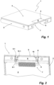
- a cover 1 for or as part of an underfloor installation box, not shown in the figures, comprises a cover frame 2 and a cover plate 3 forming its upper end.
- a cord outlet opening 4 starting from the edge of the cover plate 3 is introduced into the cover plate 3 of the cover 1.
- the cord outlet opening 4 is filled by a filler piece 5 of a closure element 6.
- the top of the filler piece 5 is aligned with the top of the cover plate 3.
- the closure element 6 with its filler piece 5 engaging in the cord outlet opening 4 is part of a closure body 7, which, as shown Figure 2 recognizable, held on the inside of the lid.
- two guide tabs 8, 8.1 are arranged on the inside of the lid.
- the guide tabs 8, 8.1 each have a section 9, 9.1 spaced from the inside of the lid by an offset.
- the space between the inside of the lid and this section 9, 9.1 serves as a guide slot in which the closure body 7 in the in Figure 2 position shown with one each Guide bar 10, 10.1 engages.
- the position of the closure body 7 shown is fixed by a detent.
- Figure 3 shows the lid 1 in a perspective view of the inside of the lid with the unlocked cord outlet opening 4.
- Figure 4 shows the closure body 7 removed from the lid 1.
- the closure body 7 has a flexible cord outlet filling 11.
- the cord outlet filling 11 as the second element of the closure body 7 provided for closing the cord outlet opening 4 is a row of brushes 12 executed.
- the row of brushes 12 allows the outlet of lines or the like through the cord outlet opening 4 of the lid, which are then led out between the individual bristles of the row of brushes 12.
- the flexible cord outlet filling 11, like the closure element 6, has two guide strips 13, 13.1.
- the guide strips 13, 13.1 are part of a frame piece 14 that is open on one side and on which the bristle holder 15 is supported.
- the level of the guide strips 13, 13.1 of the flexible cord outlet filling 11 is in a different plane than the level of the guide strips 10, 10.1 of the closure element 6.
- the two elements of the closure body 7 - the closure element 6 and the flexible cord outlet filling 11 - are as shown Figure 5 recognizable, not only arranged in two levels, but also offset from one another. While Figure 4 the spatial position of the closure body 7 for using it to close the cord outlet 4 of the lid 1, as in Figures 1 and 2 shown, represents, is in Figure 5 the closure body 7 is turned and engaged with the guide link on the cover side, so that in this position of use the flexible cord outlet filling 11 is in the position at which the closure element 6 was in Figure 4. With this spatial position, the closure body 7 with its guide strips 13, 13.1 is inserted into the guide slots of the cover 1 provided by the guide tabs 8, 8.1 if a line outlet from the cover 1 is desired.
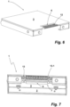
- the closure body 7 connected to the cover 1 in this way is in Figure 6 shown.
- the cord outlet opening 7 is closed by the row of brushes 12. Due to the flexibility of the bristles of the brush row 12, cables can be led into or out of an installation box through them.
- the engagement position of the guide strips 13, 13.1 of the closure body 7 in its position for closing the cord outlet opening 4 by the row of brushes 12 is off Figure 7 to recognize.
- directional arrows are attached to the tops of the guide strips 10, 10.1 and 13, 13.1, which show the translational direction of movement with which the closure body 7 closes to the lid 1 is to be mounted. Since the guide link is limited at the top by the inside of the cover plate 3 and the guide tabs 8, 8.1 with their sections 9, 9.1 are spaced from the edge of the cover plate 3, the area of the cover plate 3 that is not covered by the guide tabs 8, 8.1 in this regard can be used as Mounting stop for the guide strips 10, 10.1 or 13, 13.1 can be used if they are to be inserted into the guide slots.
Landscapes
- Engineering & Computer Science (AREA)
- Architecture (AREA)
- Civil Engineering (AREA)
- Structural Engineering (AREA)
- Connection Or Junction Boxes (AREA)
- Laying Of Electric Cables Or Lines Outside (AREA)
- Connector Housings Or Holding Contact Members (AREA)
Description
- Die Erfindung betrifft einen Deckel für eine Unterflurinstallationsdose zur Aufnahme von elektrischen/elektronischen Installationen, welcher Deckel einen Schnurauslass aufweist, dessen Schnurauslassöffnung bei Nichtbenutzung durch ein Verschlusselement und bei Benutzung zumindest teilweise mit einer eine oder mehrere Leitungen durchlassenden flexiblen Schnurauslassfüllung verschließbar ist.
- Installationsdosen für elektrische/elektronische Installationen, beispielsweise Steckdosen und dergleichen, werden für die Unterflurinstallation benötigt. Bei einer solchen Unterflurinstallation kann es sich um einen Einbau der Installationsdose in einen Hohlboden oder in einen Estrich handeln. Installationsdosen mit einem einen Schnurauslass aufweisenden Deckel werden an denjenigen Positionen eines Kabelkanalsystems, in das die Installationsdose eingeschaltet ist, angeordnet, an denen ein Zugang zu elektrischen/elektronischen Installationen erforderlich ist, beispielsweise der Zugang zu Steckdosen für die Stromversorgung elektrischer Geräte oder auch Anschlussdosen eines Datenkommunikationsnetzwerkes. Installationsdosen dieser Art verfügen vielfach über einen verstellbaren Schnurauslass, durch den die Schnurauslassöffnung des Deckels verschlossen ist, wenn aus der Installationsdose keine Leitung herausgeführt werden soll. In der anderen Stellung ist der Schnurauslass gegenüber dem oberen Abschluss des Deckels aufgeschwenkt oder angehoben, sodass dann durch die bereitgestellte Schnurauslassöffnung Leitungen oder Kabel aus der Installationsdose heraus- bzw. in diese hineingeführt werden können.
- In
DE 10 2014 101 505 A1 ist eine Installationsdose für eine Unterflurinstallation offenbart, bei der ein Verschlusselement deckelseitig verschwenkbar angelenkt ist, um aus seiner Benutzungsstellung, wenn dieses die Schnurauslassöffnung des Deckels verschließt, in eine Nichtbenutzungsstellung in Richtung zur Deckelinnenseite hin verschwenkt zu werden. Dann ist die Schnurauslassöffnung des Deckels nicht verschlossen. Bei zugeklapptem Deckel befindet sich unterhalb desselben, mit seiner Schnurauslassöffnung fluchtend, an dem Rahmen der Installationsdose eine flexible Schnurauslassfüllung, die beispielsweise als Bürstenleiste ausgeführt sein kann. Durch die Borsten der Bürstenleiste ist die Schnurauslassöffnung verschlossen. Eine aus der Installationsdose herauszuführende Leitung durchgreift die flexiblen Borsten der Bürstenreihe, die sich an die herausgeführte Leitung anschmiegen, sodass durch diese die übrige Schnurauslassöffnung gegenüber einem Eindringen von Staub oder anderweitigen Verunreinigungen in die Installationsdose verschlossen ist. Vorteilhaft bei dieser Installationsdose ist, dass auch bei einer Leitungsherausführung aus der Installationsdose von der Deckeloberseite keine feststehenden Deckelbestandteile abragen und damit eine Stolpergefahr vermieden ist. Bei dieser vorbekannten Installationsdose ist eine Positionierung des Deckels an der Installationsdose bzw. deren Rahmen nur in einer einzigen Stellung möglich, da die Schnurauslassöffnung an derjenigen Seite der Installationsdose bzw. ihres Rahmens angeordnet sein muss, an der sich die installationsdosenseitig gehaltene flexible Schnurauslassfüllung befindet. Insofern ist es erforderlich, dass der Deckel und die Installationsdose nicht nur bezüglich ihrer Bemaßung aufeinander abgestimmt sind. - Aus
US 2003/0178421 A1 ist eine weitere Installationsdose mit einem Deckel zum Verschließen seiner oberseitigen Montageöffnung bekannt. Dieser Deckel verfügt an der seinem gelenkigen Anschluss gegenüberliegenden Seite über einen Schnurauslass. Dieser ist durch ein schwenkbar daran angelenktes Verschlusselement daran gehalten. Bei Nichtgebrauch des Schnurauslasses ist das Verschlusselement eingeklappt und fluchtet mit seiner Außenseite mit der übrigen Außenseite des Deckels. Bei Benutzung des Schnurauslasses zum Auslassen ein oder mehrerer Leitungen ist das Verschlusselement entsprechend aufgeklappt. Um Beschädigungen an den aus dem Schnurauslass herausgeführten Leitungen zu vermeiden, ist das Verschlusselement innenseitig mit einem nachgiebigen Material ausgestattet. -
KR 2018 0129402 A - In
US 2009/0159308 A1 ist eine weitere Unterflurinstallationsdose mit einem Deckel beschrieben. Gemäß einer darin beschriebenen Ausgestaltung ist der Deckel schwenkbar an dem Dosenkörper angelenkt. In den Eckbereichen der im Querschnitt dreieckförmig ausgelegten Unterflurinstallationsdose befinden sich Schnurauslassöffnungen. Diese sind jeweils durch einen Klappdeckel verschließbar. Werden Leitungen durch eine solche Schnurauslassöffnung herausgeführt, befindet sich der Deckel in seiner Offenstellung, und zwar aufgeschwenkt, damit dieser zur Anlage an der Oberseite des Deckels gelangt. Zur Aufnahme des schwenkbaren Verschlusselementes ist innerhalb des Deckels eine Vertiefung vorgesehen. -
US 4,688,491 A offenbart einen Schnurauslass an der Oberfläche eines Arbeitstisches. Dieser Schnurauslass verfügt über einen Deckel mit einer Schnurauslassöffnung, die mit einem gegenüber dem Deckel verschiebbaren Verschlusselement bei Nichtbenutzung verschließbar ist. Ausgehend von diesem diskutierten Stand der Technik liegt der Erfindung daher die Aufgabe zugrunde, eine Unterflurinstallationsdose vorzuschlagen, die hinsichtlich ihrer Einsatzmöglichkeiten flexibler ist. - Gelöst wird diese Aufgabe erfindungsgemäß durch eine Unterflurinstallationsdose mit den Merkmalen des Anspruchs 1.
- Der Deckel dieser Unterflurinstallationsdose verfügt über einen Verschlusskörper. Der Verschlusskörper umfasst das Verschlusselement und die flexible Schnurauslassfüllung. Dabei sind das Verschlusselement zum Verschließen der typischerweise randlich am Deckel angeordnete Schnurauslassöffnung und die flexible Schnurauslassfüllung so zueinander angeordnet, dass der Verschlusskörper wahlweise mit seinem Verschlusselement oder seiner flexiblen Schnurauslassfüllung in der Schnurauslassöffnung des Deckels angeordnet werden kann. Der Verschlusskörper kann somit in zwei unterschiedlichen Stellungen am Deckel gehalten sein. Wenn kein Leitungsauslass gewünscht wird, wird der Verschlusskörper am Deckel angeordnet, damit sein Verschlusselement die Schnurauslassöffnung verschließt. In einer zweiten Stellung des Verschlusskörpers am Deckel ist in der Schnurauslassöffnung des Verschlusskörpers die flexible Schnurauslassfüllung angeordnet. Somit kann ein solcher Verschlusskörper in zwei unterschiedlichen Benutzungsstellungen in Bezug auf eine Füllung der Schnurauslassöffnung am Deckelteil angeordnet werden.
- Auch wenn Ausgestaltungen möglich sind, bei denen der Verschlusskörper beispielsweise um eine vertikale Achse verschwenkbar am Deckel gehalten sein kann, um je nach gewünschter Benutzung das Verschlusselement oder die flexible Schnurauslassfüllung innerhalb der Schnurauslassöffnung anzuordnen, ist vorgesehen, dass der Verschlusskörper ein von dem Deckel lösbares Teil ist. Dieser kann dann je nach der gewünschten Art seiner Verwendung, und zwar entweder dass sein Verschlusselement oder seine flexible Schnurauslassfüllung innerhalb der Schnurauslassöffnung des Deckels angeordnet werden soll, am Deckel montiert werden. Dementsprechend wird die Raumlage des Verschlusskörpers bei seiner Montage am Deckel gewählt. Vorgesehen ist, dass für die Montage des Verschlusskörpers am Deckel der Deckel innenseitig zwei Führungskulissen aufweist, in die der Verschlusskörper eingeführt und in denen er gehalten ist. Zu diesem Zweck verfügt der Verschlusskörper über entsprechende Führungsleisten, die zum Halten des Verschlusskörpers am Deckel in die deckelseitigen Führungskulissen eingreifen. Die Führungsleisten sind aus den Führungskulissen herausziehbar, damit der Verschlusskörper in der für die gewünschte Verwendung vorgesehenen Orientierung mit seinen Führungsleisten in die Führungskulisse eingeführt werden kann.
- Da der Verschlusskörper am Deckel der Installationsdose angeordnet ist, kann dieser in beliebiger Orientierung zu der eigentlichen Installationsdose bzw. ihrem Rahmen angeordnet werden. Dieses erlaubt somit eine Änderung der Schnurauslassseite auch nach bereits erfolgter Installation der Installationsdose. Da der Schnurauslass dieses Deckels mit den beiden Elementen - Verschlusselement sowie flexible Schnurauslassfüllung - allein mit dem deckelseitig gehaltenen Verschlusskörper verschließbar ist, kann dieser Deckel an beliebige Installationsdosen bzw. deren Rahmenteile angeschlossen oder zum Verschließen derselben eingesetzt werden. Die Installationsdose braucht daher keine besonderen Gestaltungsmerkmale aufweisen, damit ihre Installationsöffnung mit einem Deckel der vorbeschriebenen Art bestimmungsgemäß verschlossen werden kann. Hierdurch ist die Anwendungsvielfalt des erfindungsgemäßen Deckelteils nicht unbeträchtlich verbessert.
- Damit die beiden Elemente des Verschlusskörpers - das Verschlusselement sowie die flexible Schnurauslassfüllung - sich bei der jeweiligen Verwendung nicht behindern, ist vorgesehen, dass das Verschlusselement und die flexible Schnurauslassfüllung in zwei unterschiedlichen Ebenen und versetzt zueinander angeordnet sind. Zum Eingriff in die deckelseitigen Führungskulissen trägt jedes der beiden Elemente zwei solcher Führungsleisten. Durch simples Wenden des Verschlusskörpers kann das jeweils gewünschte Element mit seinen Führungsleisten in die deckelseitigen Führungskulissen eingesetzt und damit zum Verschließen der Schnurauslassöffnung positioniert werden. Das bei einer Anwendung jeweils nicht genutzte Element befindet sich dann deckelinnenseitig benachbart zu der Schnurauslassöffnung. Das Anordnen der beiden Elemente in zwei Ebenen erlaubt eine Verwendung eines Deckels mit einer oberseitigen Vertiefung zum Einsetzen eines Designelementes, beispielsweise einer Metallplatte, einer Teppichfliese oder eines andersartigen Bodenbelages, wie dieser beispielsweise benachbart zu der Installationsdose verlegt ist. Bei Deckeln ohne eine solche vertiefte außenseitige Aufnahme brauchen die beiden Elemente des Verschlusskörpers nicht in zwei unterschiedlichen Ebenen angeordnet zu sein.
- Das Verschlusselement selbst kann ein plattenartiges Element sein, welches an der Innenseite des Deckels, die Schnurauslassöffnung überspannend, anliegt. In einer bevorzugten Ausgestaltung ist vorgesehen, dass das Verschlusselement ein in die Schnurauslassöffnung eingreifendes und diese ausfüllendes Füllstück trägt. Bei diesem kann es sich ebenfalls um einen Bodenbelagsabschnitt handeln.
- Vorzugsweise ist der Verschlusskörper in seiner Benutzungsstellung deckelseitig fixiert. Hierfür bietet es sich an, die Fixierung als Rastfixierung auszulegen. Eine solche Fixierung vermittelt einem Benutzer zugleich eine haptische Rückmeldung, wenn der Verschlusskörper sich in der jeweiligen Benutzungsstellung befindet. Zur Rastfixierung können bei einer Ausgestaltung des Verschlusskörpers mit Führungsleisten diese genutzt werden, um zumindest an einer dieser Führungsleisten einen Rastnocken anzuformen. Dieser greift, wenn die Benutzungsstellung erreicht ist, in eine Rastnockenfalle der Führungskulisse ein oder hintergreift die Führungskulisse für die gewünschte Fixierung.
- In aller Regel wird die Montagebewegung zum Einsetzen des Verschlusskörpers in die ein oder andere Benutzungsstellung anschlagbegrenzt sein.
- Nachfolgend ist die Erfindung anhand eines Ausführungsbeispiels unter Bezugnahme auf die beigefügten Figuren beschrieben. Es zeigen:
- Fig. 1:
- Einen Deckel für eine Installationsdose in einer perspektivischen Darstellung für elektrische/elektronische Unterflurinstallationen in einer ersten Benutzungseinrichtung,
- Fig. 2:
- der Deckel der
Figur 1 in einer Teildarstellung in einer Perspektive auf seine Deckelinnenseite, - Fig. 3:
- der Deckel der vorstehenden Figuren mit vollständig geöffnetem Schnurauslass,
- Fig. 4:
- ein zum Verschließen des Schnurauslasses in den
Figuren 1 und 2 des Deckels eingesetzter Verschlusskörper in einer ersten Raumlage, - Fig. 5:
- der zum Verschließen des Schnurauslasses in den
Figuren 1 und 2 des Deckels eingesetzte Verschlusskörper in seiner für eine zweite Benutzung vorgesehenen Raumlage, - Fig. 6:
- der Deckel, dargestellt wie in
Figur 1 , mit seinem Verschlusskörper in der anderen, einen Leitungsauslass ermöglichenden Benutzungsstellung und - Fig. 7:
- eine perspektivische Ansicht des Deckels der
Figur 6 auf seine Deckelinnenseite. - Ein Deckel 1 für bzw. als Teil einer in den Figuren nicht näher dargestellten Unterflurinstallationsdose umfasst einen Deckelrahmen 2 und eine seinen oberen Abschluss bildende Deckelplatte 3. In die Deckelplatte 3 des Deckels 1 ist eine von dem Rand der Deckelplatte 3 ausgehende Schnurauslassöffnung 4 eingebracht. In der in
Figur 1 gezeigten Ausbildung des Deckels 1 ist die Schnurauslassöffnung 4 durch ein Füllstück 5 eines Verschlusselementes 6 ausgefüllt. Die Oberseite des Füllstückes 5 fluchtet mit der Oberseite der Deckelplatte 3. Das Verschlusselement 6 mit seinem in die Schnurauslassöffnung 4 eingreifenden Füllstück 5 ist Teil eines Verschlusskörpers 7, der, wie ausFigur 2 erkennbar, an der Deckelinnenseite gehalten ist. Zum Halten des Verschlusskörpers 7 sind an der Deckelinnenseite zwei Führungslaschen 8, 8.1 angeordnet. Die Führungslaschen 8, 8.1 verfügen jeweils über einen von der Deckelinnenseite durch eine Verkröpfung beabstandeten Abschnitt 9, 9.1. Der Zwischenraum zwischen der Deckelinnenseite und diesem Abschnitt 9, 9.1 dient als Führungskulisse, in der der Verschlusskörper 7 in der inFigur 2 gezeigten Stellung mit jeweils einer Führungsleiste 10, 10.1 eingreift. Die inFiguren 1 und 2 gezeigte Stellung des Verschlusskörpers 7 ist durch eine Rastung fixiert. - Nach Überwinden des Rastwiderstandes kann der Verschlusskörper 7 von dem Deckel 3 abgenommen bzw. aus der durch die Führungslaschen 8, 8.1 bereitgestellten Führungskulisse herausgezogen werden.
Figur 3 zeigt den Deckel 1 in einer perspektivischen Darstellung auf seine Deckelinnenseite mit der unverschlossenen Schnurauslassöffnung 4. -
Figur 4 zeigt den von dem Deckel 1 abgenommenen Verschlusskörper 7. Der Verschlusskörper 7 verfügt neben dem bereits beschriebenen Verschlusselement 6 mit seinem Füllstück 5 über eine flexible Schnurauslassfüllung 11. Die Schnurauslassfüllung 11 als zweites für den Verschluss der Schnurauslassöffnung 4 vorgesehenes Element des Verschlusskörpers 7 ist als Bürstenreihe 12 ausgeführt. Die Bürstenreihe 12 erlaubt den Auslass von Leitungen oder dergleichen durch die Schnurauslassöffnung 4 des Deckels, die sodann zwischen den einzelnen Borsten der Bürstenreihe 12 herausgeführt sind. Die flexible Schnurauslassfüllung 11 verfügt ebenso wie das Verschlusselement 6 über zwei Führungsleisten 13, 13.1. Die Führungsleisten 13, 13.1 sind Teil eines einseitig offenen Rahmenstücks 14, von dem die Borstenfassung 15 getragen ist. Die Ebene der Führungsleisten 13, 13.1 der flexiblen Schnurauslassfüllung 11 befindet sich in einer anderen Ebene als die Ebene der Führungsleisten 10, 10.1 des Verschlusselementes 6. Die beiden Elemente des Verschlusskörpers 7 - das Verschlusselement 6 und die flexible Schnurauslassfüllung 11 - sind, wie ausFigur 5 erkennbar, nicht nur in zwei Ebenen, sondern auch gegeneinander versetzt angeordnet. WährendFigur 4 die Raumlage des Verschlusskörpers 7 zur Verwendung desselben zum Verschließen des Schnurauslasses 4 des Deckels 1, wie inFiguren 1 und 2 gezeigt, darstellt, ist inFigur 5 der Verschlusskörper 7 gewendet mit der deckelseitigen Führungskulisse in Eingriff gestellt, sodass in dieser Benutzungsstellung die flexible Schnurauslassfüllung 11 sich an derjenigen Position befindet, an der in Figur 4 das Verschlusselement 6 war. Mit dieser Raumlage wird der Verschlusskörper 7 mit seinen Führungsleisten 13, 13.1 in die durch die Führungslaschen 8, 8.1 bereitgestellten Führungskulissen des Deckels 1 eingeschoben, wenn ein Leitungsauslass aus dem Deckel 1 gewünscht wird. - Der auf diese Weise an dem Deckel 1 angeschlossene Verschlusskörper 7 ist in
Figur 6 gezeigt. Die Schnurauslassöffnung 7 ist durch die Bürstenreihe 12 verschlossen. Aufgrund der Flexibilität der Borsten der Bürstenreihe 12 können Leitungen durch diese hindurch in eine Installationsdose ein- bzw. aus dieser herausgeführt werden. Die Eingriffsstellung der Führungsleisten 13, 13.1 des Verschlusskörpers 7 in seiner Stellung zum Verschließen der Schnurauslassöffnung 4 durch die Bürstenreihe 12 ist ausFigur 7 zu erkennen. - Zur Erleichterung der Handhabe des Verschlusskörpers 7 hinsichtlich eines bestimmungsgemäßen Anschlusses des Verschlusskörpers 7 an den Deckel 1 sind auf den Oberseiten der Führungsleisten 10, 10.1 bzw. 13, 13.1 Richtungspfeile angebracht, die die translatorische Bewegungsrichtung zeigen, mit der der Verschlusskörper 7 am Deckel 1 zu montieren ist. Da die Führungskulisse durch die Innenseite der Deckelplatte 3 oberseitig begrenzt ist und die Führungslaschen 8, 8.1 mit ihren Abschnitten 9, 9.1 von dem randlichen Abschluss der Deckelplatte 3 beabstandet sind, kann der diesbezüglich von den Führungslaschen 8, 8.1 nicht bedeckte Bereich der Deckelplatte 3 als Montageanschlag für die Führungsleisten 10, 10.1 bzw. 13, 13.1 genutzt werden, wenn diese in die Führungskulissen eingeschoben werden sollen.
- Die Erfindung ist anhand von Ausführungsbeispielen beschrieben worden. Ohne den Umfang der geltenden Ansprüche zu verlassen, ergeben sich für einen Fachmann zahlreiche weitere Möglichkeiten diese umzusetzen, ohne dass dies im Rahmen dieser Ausführungen im Einzelnen näher erläutert werden müsste.
-
- 1
- Deckel
- 2
- Deckelrahmen
- 3
- Deckelplatte
- 4
- Schnurauslassöffnung
- 5
- Füllstück
- 6
- Verschlusselement
- 7
- Verschlusskörper
- 8, 8.1
- Führungslasche
- 9, 9.1
- Abschnitt
- 10, 10.1
- Führungsleiste
- 11
- flexible Schnurauslassfüllung
- 12
- Bürstenreihe
- 13, 13.1
- Führungsleiste
- 14
- Rahmenstück
- 15
- Borstenfassung
Claims (10)
- Unterflurinstallationsdose zur Aufnahme von elektrischen/elektronischen Installationen mit einem Deckel (1), der einen Schnurauslass aufweist, dessen Schnurauslassöffnung (4) bei Nichtbenutzung durch ein Verschlusselement (6) und bei Benutzung zumindest teilweise mit einer eine oder mehrere Leitungen durchlassenden flexiblen Schnurauslassfüllung (11) verschließbar ist, dadurch gekennzeichnet, dass das Verschlusselement (6) und die flexible Schnurauslassfüllung (11) Teil eines deckelseitig gehaltenen Verschlusskörpers (7) sind, der in einer ersten am Deckel gehaltenen Stellung mit seinem Verschlusselement (6) und in einer zweiten am Deckel gehaltenen Stellung mit seiner flexiblen Schnurauslassfüllung (11) in der Schnurauslassöffnung (4) des Deckels (1) anordnenbar ist, dass der Deckel (1) innenseitig zwei Führungskulissen aufweist, in denen der Verschlusskörper (7), mit jeweils einer Führungsleiste (10, 10.1; 13, 13.1) in eine Führungskulisse eingreifend, und indem jedes der beiden Elemente des Verschlusskörpers zwei Führungsleisten trägt, in der einen, in der das Verschlusselement (6) in der Schnurauslassöffnung (4) angeordnet ist, oder der anderen Stellung, in der die flexible Schnurauslassfüllung (11) in der Schnurauslassöffnung (4) angeordnet ist, gehalten ist, dass das Verschlusselement (6) und die Schnurauslassfüllung (11) des Verschlusskörpers (7) in unterschiedlichen Ebenen und mit ihren in ihrer jeweiligen Benutzungsstellung zur Schnurauslassöffnung (4) weisenden Seiten in voneinander wegweisende Richtungen angeordnet sind, und dass das Verschlusselement (6) und die Schnurauslassfüllung (11) versetzt zueinander angeordnet sind.
- Unterflurinstallationsdose nach Anspruch 1, dadurch gekennzeichnet, dass die Führungsleisten (10, 10.1; 13, 13.1) des Verschlusskörpers (7) aus den Führungskulissen herausziehbar sind.
- Unterflurinstallationsdose nach Anspruch 1 oder 2, dadurch gekennzeichnet, dass die Führungskulissen jeweils durch eine an der Deckelinnenseite benachbart zu der Schnurauslassöffnung (4) befindliche, einen durch eine Verkröpfung von der Deckelinnenseite beabstandeten Abschnitt (9, 9.1) aufweisende Führungslasche (8, 8.1) realisiert sind.
- Unterflurinstallationsdose nach einem der Ansprüche 1 bis 3, dadurch gekennzeichnet, dass das Verschlusselement (6) ein in die Schnurauslassöffnung (4) eingreifendes und diese ausfüllendes Füllstück (5) trägt.
- Unterflurinstallationsdose nach einem der Ansprüche 1 bis 4, dadurch gekennzeichnet, dass die flexible Schnurauslassfüllung (11) als Bürstenleiste (12) ausgeführt ist.
- Unterflurinstallationsdose nach Anspruch 5, dadurch gekennzeichnet, dass die Borsten der Bürstenleiste (12) dergestalt geneigt gehalten sind, damit diese mit ihren freien Enden im Wesentlichen mit der Deckeloberseite abschließen.
- Unterflurinstallationsdose nach einem der Ansprüche 1 bis 6, dadurch gekennzeichnet, dass der Verschlusskörper (7) in seinen Benutzungsstellungen am Deckel (1) fixiert ist.
- Unterflurinstallationsdose nach Anspruch 7, dadurch gekennzeichnet, dass der Verschlusskörper (7) durch eine Rastung in seinen Benutzungsstellungen am Deckel (1) fixiert ist.
- Unterflurinstallationsdose nach Anspruch 8, dadurch gekennzeichnet, dass zur Rastfixierung des Verschlusskörpers (7) zumindest einer der beiden in eine Führungskulisse eingreifenden Führungsleisten (10, 10.1; 13, 13.1) einen Rastnocken trägt, der, wenn sich der Verschlusskörper in Benutzungsstellung befindet, in eine Rastnockenfalle der Führungskulisse eingreift oder die Führungskulisse hintergreift.
- Unterflurinstallationsdose nach einem der Ansprüche 1 bis 9 dadurch gekennzeichnet, dass der Deckel (1) schwenkbar an der Unterflurinstallationsdose angelenkt ist.
Applications Claiming Priority (1)
| Application Number | Priority Date | Filing Date | Title |
|---|---|---|---|
| DE202020106720.6U DE202020106720U1 (de) | 2020-11-23 | 2020-11-23 | Deckel für eine Installationsdose |
Publications (2)
| Publication Number | Publication Date |
|---|---|
| EP4002618A1 EP4002618A1 (de) | 2022-05-25 |
| EP4002618B1 true EP4002618B1 (de) | 2023-10-11 |
Family
ID=78695530
Family Applications (1)
| Application Number | Title | Priority Date | Filing Date |
|---|---|---|---|
| EP21208901.5A Active EP4002618B1 (de) | 2020-11-23 | 2021-11-18 | Unterflurinstallationsdose |
Country Status (7)
| Country | Link |
|---|---|
| EP (1) | EP4002618B1 (de) |
| DE (1) | DE202020106720U1 (de) |
| ES (1) | ES2967465T3 (de) |
| FI (1) | FI4002618T3 (de) |
| LT (1) | LT4002618T (de) |
| PL (1) | PL4002618T3 (de) |
| PT (1) | PT4002618T (de) |
Families Citing this family (1)
| Publication number | Priority date | Publication date | Assignee | Title |
|---|---|---|---|---|
| DE202022100257U1 (de) * | 2022-01-18 | 2022-11-10 | Obo Bettermann Hungary Kft | Bodentankdose |
Citations (1)
| Publication number | Priority date | Publication date | Assignee | Title |
|---|---|---|---|---|
| GB2450556A (en) * | 2007-06-29 | 2008-12-31 | Novar Ed & S Ltd | Service outlet floor box |
Family Cites Families (6)
| Publication number | Priority date | Publication date | Assignee | Title |
|---|---|---|---|---|
| US4688491A (en) * | 1986-09-08 | 1987-08-25 | Allsteel Inc. | Grommet arrangement for office furniture desk tops |
| CA2375554C (en) | 2002-03-08 | 2010-03-16 | Gordon S. Almond | Telecommunication and electrical service box for mounting in a floor |
| US8119912B2 (en) * | 2006-08-29 | 2012-02-21 | The Wiremold Company | Cover assembly for an in-floor box |
| US8110743B2 (en) * | 2008-02-22 | 2012-02-07 | Thomas & Betts International, Inc. | Electrical box cover with insect guard |
| DE102014101505B4 (de) | 2014-02-06 | 2016-06-30 | Puk-Werke Kg Kunststoff-Stahlverarbeitung Gmbh & Co. | Einbaueinheit, Kanalsystem, Fußboden sowie Verwendung einer Einbaueinheit oder eines Kanalsystems zum Betreiben eines elektrischen Gerätes |
| KR20180129402A (ko) * | 2017-05-26 | 2018-12-05 | 정봉춘 | 회전 커버 방식의 시스템 박스 |
-
2020
- 2020-11-23 DE DE202020106720.6U patent/DE202020106720U1/de active Active
-
2021
- 2021-11-18 ES ES21208901T patent/ES2967465T3/es active Active
- 2021-11-18 PL PL21208901.5T patent/PL4002618T3/pl unknown
- 2021-11-18 EP EP21208901.5A patent/EP4002618B1/de active Active
- 2021-11-18 FI FIEP21208901.5T patent/FI4002618T3/fi active
- 2021-11-18 LT LTEP21208901.5T patent/LT4002618T/lt unknown
- 2021-11-18 PT PT212089015T patent/PT4002618T/pt unknown
Patent Citations (1)
| Publication number | Priority date | Publication date | Assignee | Title |
|---|---|---|---|---|
| GB2450556A (en) * | 2007-06-29 | 2008-12-31 | Novar Ed & S Ltd | Service outlet floor box |
Also Published As
| Publication number | Publication date |
|---|---|
| EP4002618A1 (de) | 2022-05-25 |
| DE202020106720U1 (de) | 2021-11-10 |
| PL4002618T3 (pl) | 2024-02-12 |
| PT4002618T (pt) | 2023-12-19 |
| ES2967465T3 (es) | 2024-04-30 |
| FI4002618T3 (fi) | 2023-12-12 |
| LT4002618T (lt) | 2023-12-11 |
Similar Documents
| Publication | Publication Date | Title |
|---|---|---|
| DE69923093T2 (de) | Kabelkanal mit Steckdose | |
| DE60101923T2 (de) | Kabelkanalsystemscharnieranordnung | |
| EP1678798B1 (de) | Gehäuse | |
| CH662675A5 (de) | Kabel-wanddurchfuehrung. | |
| EP0648000B1 (de) | Unterflurgerätedose für nass zu reinigende Böden | |
| EP4002618B1 (de) | Unterflurinstallationsdose | |
| EP3221940B1 (de) | Leitungsdurchführung | |
| EP0584444A1 (de) | Montageelement für Installationskanäle | |
| DE20320702U1 (de) | Wandauslassdose | |
| DE102015116716B4 (de) | Verteilerblock mit Berührschutzanordnung | |
| DE102024103048A1 (de) | Zähler- und Verteilerschrank | |
| DE4222656A1 (de) | Elektrische Steckdose | |
| DE3510390C2 (de) | Abgangsstelle für Stromschienen mit Sicherheitsvorrichtung an Schienen-Verteilersystemen | |
| DE10050279A1 (de) | Flexfolienverlegehilfe | |
| DE29903000U1 (de) | Isoliergehäuse für Verteilerklemme | |
| EP1463170B1 (de) | Zähler- und/oder Verteilerschrank | |
| DE19811713C2 (de) | Schaltschrank | |
| DE19814567A1 (de) | Einbaudose zur Verwendung in Kabelkanälen, wie Brüstungskanälen | |
| WO2018050651A1 (de) | Gehäuse für ein steuergerät und abdeckhaube für das gehäuse | |
| DE102015118903A1 (de) | Kabelführungselement | |
| EP0910146A1 (de) | Gehäuse | |
| EP3217495A1 (de) | Kabelkanal | |
| EP1359650A1 (de) | Anschlussvorrichtung für elektrische Verteiler | |
| EP2863501B1 (de) | Verbindungselement, Kastenteil und Bausatz zur Bildung eines in eine Wandnische einzubauenden Kastens | |
| EP2415136A2 (de) | Gehäuseanordnung |
Legal Events
| Date | Code | Title | Description |
|---|---|---|---|
| PUAI | Public reference made under article 153(3) epc to a published international application that has entered the european phase |
Free format text: ORIGINAL CODE: 0009012 |
|
| STAA | Information on the status of an ep patent application or granted ep patent |
Free format text: STATUS: THE APPLICATION HAS BEEN PUBLISHED |
|
| STAA | Information on the status of an ep patent application or granted ep patent |
Free format text: STATUS: REQUEST FOR EXAMINATION WAS MADE |
|
| AK | Designated contracting states |
Kind code of ref document: A1 Designated state(s): AL AT BE BG CH CY CZ DE DK EE ES FI FR GB GR HR HU IE IS IT LI LT LU LV MC MK MT NL NO PL PT RO RS SE SI SK SM TR |
|
| 17P | Request for examination filed |
Effective date: 20220503 |
|
| RBV | Designated contracting states (corrected) |
Designated state(s): AL AT BE BG CH CY CZ DE DK EE ES FI FR GB GR HR HU IE IS IT LI LT LU LV MC MK MT NL NO PL PT RO RS SE SI SK SM TR |
|
| GRAP | Despatch of communication of intention to grant a patent |
Free format text: ORIGINAL CODE: EPIDOSNIGR1 |
|
| STAA | Information on the status of an ep patent application or granted ep patent |
Free format text: STATUS: GRANT OF PATENT IS INTENDED |
|
| INTG | Intention to grant announced |
Effective date: 20230614 |
|
| P01 | Opt-out of the competence of the unified patent court (upc) registered |
Effective date: 20230529 |
|
| GRAS | Grant fee paid |
Free format text: ORIGINAL CODE: EPIDOSNIGR3 |
|
| GRAA | (expected) grant |
Free format text: ORIGINAL CODE: 0009210 |
|
| STAA | Information on the status of an ep patent application or granted ep patent |
Free format text: STATUS: THE PATENT HAS BEEN GRANTED |
|
| AK | Designated contracting states |
Kind code of ref document: B1 Designated state(s): AL AT BE BG CH CY CZ DE DK EE ES FI FR GB GR HR HU IE IS IT LI LT LU LV MC MK MT NL NO PL PT RO RS SE SI SK SM TR |
|
| REG | Reference to a national code |
Ref country code: GB Ref legal event code: FG4D Free format text: NOT ENGLISH |
|
| REG | Reference to a national code |
Ref country code: CH Ref legal event code: EP |
|
| REG | Reference to a national code |
Ref country code: DE Ref legal event code: R096 Ref document number: 502021001686 Country of ref document: DE |
|
| REG | Reference to a national code |
Ref country code: IE Ref legal event code: FG4D Free format text: LANGUAGE OF EP DOCUMENT: GERMAN |
|
| REG | Reference to a national code |
Ref country code: FI Ref legal event code: FGE |
|
| REG | Reference to a national code |
Ref country code: PT Ref legal event code: SC4A Ref document number: 4002618 Country of ref document: PT Date of ref document: 20231219 Kind code of ref document: T Free format text: AVAILABILITY OF NATIONAL TRANSLATION Effective date: 20231212 |
|
| REG | Reference to a national code |
Ref country code: NL Ref legal event code: FP |
|
| PG25 | Lapsed in a contracting state [announced via postgrant information from national office to epo] |
Ref country code: GR Free format text: LAPSE BECAUSE OF FAILURE TO SUBMIT A TRANSLATION OF THE DESCRIPTION OR TO PAY THE FEE WITHIN THE PRESCRIBED TIME-LIMIT Effective date: 20240112 |
|
| PG25 | Lapsed in a contracting state [announced via postgrant information from national office to epo] |
Ref country code: IS Free format text: LAPSE BECAUSE OF FAILURE TO SUBMIT A TRANSLATION OF THE DESCRIPTION OR TO PAY THE FEE WITHIN THE PRESCRIBED TIME-LIMIT Effective date: 20240211 |
|
| PG25 | Lapsed in a contracting state [announced via postgrant information from national office to epo] |
Ref country code: IS Free format text: LAPSE BECAUSE OF FAILURE TO SUBMIT A TRANSLATION OF THE DESCRIPTION OR TO PAY THE FEE WITHIN THE PRESCRIBED TIME-LIMIT Effective date: 20240211 Ref country code: GR Free format text: LAPSE BECAUSE OF FAILURE TO SUBMIT A TRANSLATION OF THE DESCRIPTION OR TO PAY THE FEE WITHIN THE PRESCRIBED TIME-LIMIT Effective date: 20240112 Ref country code: BG Free format text: LAPSE BECAUSE OF FAILURE TO SUBMIT A TRANSLATION OF THE DESCRIPTION OR TO PAY THE FEE WITHIN THE PRESCRIBED TIME-LIMIT Effective date: 20240111 |
|
| REG | Reference to a national code |
Ref country code: ES Ref legal event code: FG2A Ref document number: 2967465 Country of ref document: ES Kind code of ref document: T3 Effective date: 20240430 |
|
| PG25 | Lapsed in a contracting state [announced via postgrant information from national office to epo] |
Ref country code: SE Free format text: LAPSE BECAUSE OF FAILURE TO SUBMIT A TRANSLATION OF THE DESCRIPTION OR TO PAY THE FEE WITHIN THE PRESCRIBED TIME-LIMIT Effective date: 20231011 Ref country code: RS Free format text: LAPSE BECAUSE OF FAILURE TO SUBMIT A TRANSLATION OF THE DESCRIPTION OR TO PAY THE FEE WITHIN THE PRESCRIBED TIME-LIMIT Effective date: 20231011 Ref country code: NO Free format text: LAPSE BECAUSE OF FAILURE TO SUBMIT A TRANSLATION OF THE DESCRIPTION OR TO PAY THE FEE WITHIN THE PRESCRIBED TIME-LIMIT Effective date: 20240111 Ref country code: LV Free format text: LAPSE BECAUSE OF FAILURE TO SUBMIT A TRANSLATION OF THE DESCRIPTION OR TO PAY THE FEE WITHIN THE PRESCRIBED TIME-LIMIT Effective date: 20231011 Ref country code: HR Free format text: LAPSE BECAUSE OF FAILURE TO SUBMIT A TRANSLATION OF THE DESCRIPTION OR TO PAY THE FEE WITHIN THE PRESCRIBED TIME-LIMIT Effective date: 20231011 |
|
| PG25 | Lapsed in a contracting state [announced via postgrant information from national office to epo] |
Ref country code: DK Free format text: LAPSE BECAUSE OF FAILURE TO SUBMIT A TRANSLATION OF THE DESCRIPTION OR TO PAY THE FEE WITHIN THE PRESCRIBED TIME-LIMIT Effective date: 20231011 |
|
| REG | Reference to a national code |
Ref country code: DE Ref legal event code: R097 Ref document number: 502021001686 Country of ref document: DE |
|
| PG25 | Lapsed in a contracting state [announced via postgrant information from national office to epo] |
Ref country code: CZ Free format text: LAPSE BECAUSE OF FAILURE TO SUBMIT A TRANSLATION OF THE DESCRIPTION OR TO PAY THE FEE WITHIN THE PRESCRIBED TIME-LIMIT Effective date: 20231011 |
|
| PG25 | Lapsed in a contracting state [announced via postgrant information from national office to epo] |
Ref country code: SK Free format text: LAPSE BECAUSE OF FAILURE TO SUBMIT A TRANSLATION OF THE DESCRIPTION OR TO PAY THE FEE WITHIN THE PRESCRIBED TIME-LIMIT Effective date: 20231011 |
|
| PG25 | Lapsed in a contracting state [announced via postgrant information from national office to epo] |
Ref country code: SM Free format text: LAPSE BECAUSE OF FAILURE TO SUBMIT A TRANSLATION OF THE DESCRIPTION OR TO PAY THE FEE WITHIN THE PRESCRIBED TIME-LIMIT Effective date: 20231011 Ref country code: SK Free format text: LAPSE BECAUSE OF FAILURE TO SUBMIT A TRANSLATION OF THE DESCRIPTION OR TO PAY THE FEE WITHIN THE PRESCRIBED TIME-LIMIT Effective date: 20231011 Ref country code: RO Free format text: LAPSE BECAUSE OF FAILURE TO SUBMIT A TRANSLATION OF THE DESCRIPTION OR TO PAY THE FEE WITHIN THE PRESCRIBED TIME-LIMIT Effective date: 20231011 Ref country code: EE Free format text: LAPSE BECAUSE OF FAILURE TO SUBMIT A TRANSLATION OF THE DESCRIPTION OR TO PAY THE FEE WITHIN THE PRESCRIBED TIME-LIMIT Effective date: 20231011 Ref country code: DK Free format text: LAPSE BECAUSE OF FAILURE TO SUBMIT A TRANSLATION OF THE DESCRIPTION OR TO PAY THE FEE WITHIN THE PRESCRIBED TIME-LIMIT Effective date: 20231011 Ref country code: CZ Free format text: LAPSE BECAUSE OF FAILURE TO SUBMIT A TRANSLATION OF THE DESCRIPTION OR TO PAY THE FEE WITHIN THE PRESCRIBED TIME-LIMIT Effective date: 20231011 |
|
| PLBE | No opposition filed within time limit |
Free format text: ORIGINAL CODE: 0009261 |
|
| STAA | Information on the status of an ep patent application or granted ep patent |
Free format text: STATUS: NO OPPOSITION FILED WITHIN TIME LIMIT |
|
| PG25 | Lapsed in a contracting state [announced via postgrant information from national office to epo] |
Ref country code: MC Free format text: LAPSE BECAUSE OF FAILURE TO SUBMIT A TRANSLATION OF THE DESCRIPTION OR TO PAY THE FEE WITHIN THE PRESCRIBED TIME-LIMIT Effective date: 20231011 |
|
| PG25 | Lapsed in a contracting state [announced via postgrant information from national office to epo] |
Ref country code: MC Free format text: LAPSE BECAUSE OF FAILURE TO SUBMIT A TRANSLATION OF THE DESCRIPTION OR TO PAY THE FEE WITHIN THE PRESCRIBED TIME-LIMIT Effective date: 20231011 |
|
| REG | Reference to a national code |
Ref country code: IE Ref legal event code: MM4A |
|
| 26N | No opposition filed |
Effective date: 20240712 |
|
| PG25 | Lapsed in a contracting state [announced via postgrant information from national office to epo] |
Ref country code: IE Free format text: LAPSE BECAUSE OF NON-PAYMENT OF DUE FEES Effective date: 20231118 |
|
| PG25 | Lapsed in a contracting state [announced via postgrant information from national office to epo] |
Ref country code: SI Free format text: LAPSE BECAUSE OF FAILURE TO SUBMIT A TRANSLATION OF THE DESCRIPTION OR TO PAY THE FEE WITHIN THE PRESCRIBED TIME-LIMIT Effective date: 20231011 |
|
| PG25 | Lapsed in a contracting state [announced via postgrant information from national office to epo] |
Ref country code: SI Free format text: LAPSE BECAUSE OF FAILURE TO SUBMIT A TRANSLATION OF THE DESCRIPTION OR TO PAY THE FEE WITHIN THE PRESCRIBED TIME-LIMIT Effective date: 20231011 Ref country code: IE Free format text: LAPSE BECAUSE OF NON-PAYMENT OF DUE FEES Effective date: 20231118 |
|
| PGFP | Annual fee paid to national office [announced via postgrant information from national office to epo] |
Ref country code: LU Payment date: 20241119 Year of fee payment: 4 Ref country code: NL Payment date: 20241120 Year of fee payment: 4 |
|
| PGFP | Annual fee paid to national office [announced via postgrant information from national office to epo] |
Ref country code: LT Payment date: 20241107 Year of fee payment: 4 |
|
| PGFP | Annual fee paid to national office [announced via postgrant information from national office to epo] |
Ref country code: PL Payment date: 20241021 Year of fee payment: 4 Ref country code: FI Payment date: 20241119 Year of fee payment: 4 |
|
| PGFP | Annual fee paid to national office [announced via postgrant information from national office to epo] |
Ref country code: ES Payment date: 20241213 Year of fee payment: 4 |
|
| PGFP | Annual fee paid to national office [announced via postgrant information from national office to epo] |
Ref country code: CH Payment date: 20241201 Year of fee payment: 4 |
|
| PG25 | Lapsed in a contracting state [announced via postgrant information from national office to epo] |
Ref country code: CY Free format text: LAPSE BECAUSE OF FAILURE TO SUBMIT A TRANSLATION OF THE DESCRIPTION OR TO PAY THE FEE WITHIN THE PRESCRIBED TIME-LIMIT; INVALID AB INITIO Effective date: 20211118 |
|
| PGFP | Annual fee paid to national office [announced via postgrant information from national office to epo] |
Ref country code: PT Payment date: 20251105 Year of fee payment: 5 |
|
| PG25 | Lapsed in a contracting state [announced via postgrant information from national office to epo] |
Ref country code: TR Free format text: LAPSE BECAUSE OF FAILURE TO SUBMIT A TRANSLATION OF THE DESCRIPTION OR TO PAY THE FEE WITHIN THE PRESCRIBED TIME-LIMIT Effective date: 20231011 |
|
| PGFP | Annual fee paid to national office [announced via postgrant information from national office to epo] |
Ref country code: DE Payment date: 20251013 Year of fee payment: 5 |
|
| PGFP | Annual fee paid to national office [announced via postgrant information from national office to epo] |
Ref country code: GB Payment date: 20251120 Year of fee payment: 5 |
|
| PGFP | Annual fee paid to national office [announced via postgrant information from national office to epo] |
Ref country code: AT Payment date: 20260113 Year of fee payment: 5 |
|
| PGFP | Annual fee paid to national office [announced via postgrant information from national office to epo] |
Ref country code: IT Payment date: 20251128 Year of fee payment: 5 |
|
| PGFP | Annual fee paid to national office [announced via postgrant information from national office to epo] |
Ref country code: FR Payment date: 20251120 Year of fee payment: 5 |
|
| PGFP | Annual fee paid to national office [announced via postgrant information from national office to epo] |
Ref country code: BE Payment date: 20251118 Year of fee payment: 5 |
|
| PG25 | Lapsed in a contracting state [announced via postgrant information from national office to epo] |
Ref country code: HU Free format text: LAPSE BECAUSE OF FAILURE TO SUBMIT A TRANSLATION OF THE DESCRIPTION OR TO PAY THE FEE WITHIN THE PRESCRIBED TIME-LIMIT; INVALID AB INITIO Effective date: 20211118 |