EP4002618B1 - Boîte d'installation souterrain - Google Patents
Boîte d'installation souterrain Download PDFInfo
- Publication number
- EP4002618B1 EP4002618B1 EP21208901.5A EP21208901A EP4002618B1 EP 4002618 B1 EP4002618 B1 EP 4002618B1 EP 21208901 A EP21208901 A EP 21208901A EP 4002618 B1 EP4002618 B1 EP 4002618B1
- Authority
- EP
- European Patent Office
- Prior art keywords
- cord outlet
- cover
- installation box
- closure body
- outlet opening
- Prior art date
- Legal status (The legal status is an assumption and is not a legal conclusion. Google has not performed a legal analysis and makes no representation as to the accuracy of the status listed.)
- Active
Links
Images

Classifications
-
- H—ELECTRICITY
- H02—GENERATION; CONVERSION OR DISTRIBUTION OF ELECTRIC POWER
- H02G—INSTALLATION OF ELECTRIC CABLES OR LINES, OR OF COMBINED OPTICAL AND ELECTRIC CABLES OR LINES
- H02G3/00—Installations of electric cables or lines or protective tubing therefor in or on buildings, equivalent structures or vehicles
- H02G3/02—Details
- H02G3/08—Distribution boxes; Connection or junction boxes
- H02G3/18—Distribution boxes; Connection or junction boxes providing line outlets
- H02G3/185—Floor outlets and access cups
-
- H—ELECTRICITY
- H02—GENERATION; CONVERSION OR DISTRIBUTION OF ELECTRIC POWER
- H02G—INSTALLATION OF ELECTRIC CABLES OR LINES, OR OF COMBINED OPTICAL AND ELECTRIC CABLES OR LINES
- H02G3/00—Installations of electric cables or lines or protective tubing therefor in or on buildings, equivalent structures or vehicles
- H02G3/02—Details
- H02G3/08—Distribution boxes; Connection or junction boxes
- H02G3/14—Fastening of cover or lid to box
Definitions
- the invention relates to a cover for an underfloor installation box for accommodating electrical/electronic installations, which cover has a cord outlet, the cord outlet opening of which can be closed when not in use by a closure element and when in use at least partially with a flexible cord outlet filling that allows one or more lines to pass through.
- Installation boxes for electrical/electronic installations are required for underfloor installation.
- Such an underfloor installation can involve installing the installation box in a hollow floor or in a screed.
- Installation boxes with a cover having a cord outlet are arranged at those positions of a cable duct system in which the installation box is switched on, where access to electrical/electronic installations is required, for example access to sockets for powering electrical devices or also connection boxes of a data communication network .
- Installation boxes of this type often have an adjustable cord outlet, through which the cord outlet opening of the lid is closed if no cable is to be led out of the installation box. In the other position, the cord outlet is swiveled or raised relative to the upper end of the lid, so that lines or cables can then be led out of or into the installation box through the cord outlet opening provided.
- an installation box for an underfloor installation in which a closure element is pivotally articulated on the lid side in order to be pivoted from its use position, when it closes the cord outlet opening of the lid, into a non-use position towards the inside of the lid. Then the cord outlet opening of the lid is not closed.
- the lid When the lid is closed, there is a flexible one underneath it, aligned with its cord outlet opening, on the frame of the installation box
- Cord outlet filling which can be designed as a brush strip, for example. The cord outlet opening is closed by the bristles on the brush strip.
- a cable to be led out of the installation box passes through the flexible bristles of the row of brushes, which nestle against the cable that is led out, so that the remaining cord outlet opening is closed against the ingress of dust or other contaminants into the installation box.
- the advantage of this installation box is that even when the cable is led out of the installation box, no fixed cover components protrude from the top of the cover, thus avoiding the risk of tripping.
- positioning of the cover on the installation box or its frame is only possible in a single position, since the cord outlet opening must be arranged on that side of the installation box or its frame on which the flexible cord outlet filling held on the installation box side is located. In this respect, it is necessary that the cover and the installation box are coordinated not only in terms of their dimensions.
- KR 2018 0129402 A reveals an underfloor installation box.
- the installation box there is a support structure with a tubular elastic element projecting from it towards a cover.
- a cover is connected to this, which is circumferentially mounted on a flange Frame part sits on. Due to the connection to the elastic element, it can be rotated in the circumferential direction.
- the top of the frame member is mounted flush with the adjacent surface of a floor.
- a closure body is assigned to each cord outlet opening.
- the closure body has a closure element and a lace outlet hood.
- Such a closure body can be mounted on the cover either in a position for closing the cord outlet opening or for letting out a cable with its cord outlet hood in the cord outlet opening.
- the closure element is located in the cord outlet opening.
- the cord outlet hood is located above the cord outlet opening. The cord outlet hood protrudes from the top of the cover and is used for cable routing so that a cable leading out of it is guided away from the underfloor installation box in the radial direction.
- US 4,688,491A reveals a cord outlet on the surface of a work table.
- This cord outlet has a lid with a cord outlet opening that can be closed when not in use with a closure element that can be moved relative to the lid.
- the invention is therefore based on the object of proposing an underfloor installation box that is more flexible in terms of its possible uses.
- the lid of this underfloor installation box has a locking body.
- the closure body includes the closure element and the flexible cord outlet filling.
- the closure element for closing the cord outlet opening which is typically arranged at the edge of the lid, and the flexible cord outlet filling are arranged relative to one another in such a way that the closure body can be arranged either with its closure element or its flexible cord outlet filling in the cord outlet opening of the lid.
- the closure body can therefore be held on the lid in two different positions. If no line outlet is desired, the closure body is arranged on the lid so that its closure element closes the cord outlet opening. In a second position of the closure body on the lid, the flexible cord outlet filling is arranged in the cord outlet opening of the closure body.
- such a closure body can be arranged in two different positions of use with respect to filling the cord outlet opening on the cover part.
- the closure body can be held on the lid so that it can pivot about a vertical axis, for example, in order to arrange the closure element or the flexible cord outlet filling within the cord outlet opening depending on the desired use, it is provided that the closure body is a part that can be detached from the lid is. This can then be mounted on the lid depending on the desired type of use, namely either that its closure element or its flexible cord outlet filling is to be arranged within the cord outlet opening of the lid. The spatial position of the closure body is selected accordingly when it is mounted on the lid. It is intended that for the assembly of the closure body on the lid, the lid has two guide slots on the inside, into which the closure body is inserted and in which it is held.
- the closure body has appropriate guide strips, which engage in the guide slots on the lid side to hold the closure body on the lid.
- the guide strips can be pulled out of the guide slots so that the closure body can be inserted into the guide slot with its guide strips in the orientation intended for the desired use.
- the closure body Since the closure body is arranged on the cover of the installation box, it can be arranged in any orientation to the actual installation box or its frame. This allows the cord outlet side to be changed even after the installation box has already been installed. Since the cord outlet of this lid with the two elements - closure element and flexible cord outlet filling - can be closed solely with the closure body held on the lid side, this lid can be connected to any installation boxes or their frame parts or used to close them.
- the installation box therefore does not need to have any special design features so that its installation opening can be closed as intended with a cover of the type described above. As a result, the variety of applications of the cover part according to the invention is not insignificantly improved.
- each of the two elements carries two such guide strips.
- the desired element with its guide strips can be inserted into the guide slots on the cover side and thus positioned to close the cord outlet opening.
- the element that is not used in an application is then located on the inside of the cover adjacent to the cord outlet opening.
- Arranging the two elements in two levels allows the use of a lid with a recess on the top for inserting a design element, for example a metal plate, a carpet tile or another type of floor covering, such as that laid adjacent to the installation box.
- a design element for example a metal plate, a carpet tile or another type of floor covering, such as that laid adjacent to the installation box.
- the two elements of the closure body do not need to be arranged in two different planes.
- the closure element itself can be a plate-like element which rests on the inside of the lid, spanning the cord outlet opening.
- the closure element carries a filler piece which engages in the cord outlet opening and fills it. This can also be a floor covering section.
- the closure body is preferably fixed on the lid side in its position of use.
- the fixation is advisable to design the fixation as a snap-in fixation.
- Such a fixation also provides a user with haptic feedback when the closure body is in the respective position of use.
- these can be used to form a locking cam on at least one of these guide strips. When the use position is reached, this engages in a locking cam latch of the guide link or engages behind the guide link for the desired fixation.
- the assembly movement for inserting the closure body into one or the other position of use will be stop-limited.
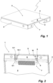
- a cover 1 for or as part of an underfloor installation box, not shown in the figures, comprises a cover frame 2 and a cover plate 3 forming its upper end.
- a cord outlet opening 4 starting from the edge of the cover plate 3 is introduced into the cover plate 3 of the cover 1.
- the cord outlet opening 4 is filled by a filler piece 5 of a closure element 6.
- the top of the filler piece 5 is aligned with the top of the cover plate 3.
- the closure element 6 with its filler piece 5 engaging in the cord outlet opening 4 is part of a closure body 7, which, as shown Figure 2 recognizable, held on the inside of the lid.
- two guide tabs 8, 8.1 are arranged on the inside of the lid.
- the guide tabs 8, 8.1 each have a section 9, 9.1 spaced from the inside of the lid by an offset.
- the space between the inside of the lid and this section 9, 9.1 serves as a guide slot in which the closure body 7 in the in Figure 2 position shown with one each Guide bar 10, 10.1 engages.
- the position of the closure body 7 shown is fixed by a detent.
- Figure 3 shows the lid 1 in a perspective view of the inside of the lid with the unlocked cord outlet opening 4.
- Figure 4 shows the closure body 7 removed from the lid 1.
- the closure body 7 has a flexible cord outlet filling 11.
- the cord outlet filling 11 as the second element of the closure body 7 provided for closing the cord outlet opening 4 is a row of brushes 12 executed.
- the row of brushes 12 allows the outlet of lines or the like through the cord outlet opening 4 of the lid, which are then led out between the individual bristles of the row of brushes 12.
- the flexible cord outlet filling 11, like the closure element 6, has two guide strips 13, 13.1.
- the guide strips 13, 13.1 are part of a frame piece 14 that is open on one side and on which the bristle holder 15 is supported.
- the level of the guide strips 13, 13.1 of the flexible cord outlet filling 11 is in a different plane than the level of the guide strips 10, 10.1 of the closure element 6.
- the two elements of the closure body 7 - the closure element 6 and the flexible cord outlet filling 11 - are as shown Figure 5 recognizable, not only arranged in two levels, but also offset from one another. While Figure 4 the spatial position of the closure body 7 for using it to close the cord outlet 4 of the lid 1, as in Figures 1 and 2 shown, represents, is in Figure 5 the closure body 7 is turned and engaged with the guide link on the cover side, so that in this position of use the flexible cord outlet filling 11 is in the position at which the closure element 6 was in Figure 4. With this spatial position, the closure body 7 with its guide strips 13, 13.1 is inserted into the guide slots of the cover 1 provided by the guide tabs 8, 8.1 if a line outlet from the cover 1 is desired.
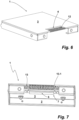
- the closure body 7 connected to the cover 1 in this way is in Figure 6 shown.
- the cord outlet opening 7 is closed by the row of brushes 12. Due to the flexibility of the bristles of the brush row 12, cables can be led into or out of an installation box through them.
- the engagement position of the guide strips 13, 13.1 of the closure body 7 in its position for closing the cord outlet opening 4 by the row of brushes 12 is off Figure 7 to recognize.
- directional arrows are attached to the tops of the guide strips 10, 10.1 and 13, 13.1, which show the translational direction of movement with which the closure body 7 closes to the lid 1 is to be mounted. Since the guide link is limited at the top by the inside of the cover plate 3 and the guide tabs 8, 8.1 with their sections 9, 9.1 are spaced from the edge of the cover plate 3, the area of the cover plate 3 that is not covered by the guide tabs 8, 8.1 in this regard can be used as Mounting stop for the guide strips 10, 10.1 or 13, 13.1 can be used if they are to be inserted into the guide slots.
Landscapes
- Engineering & Computer Science (AREA)
- Architecture (AREA)
- Civil Engineering (AREA)
- Structural Engineering (AREA)
- Connection Or Junction Boxes (AREA)
- Laying Of Electric Cables Or Lines Outside (AREA)
- Connector Housings Or Holding Contact Members (AREA)
Claims (10)
- Boîtier d'installation sous plancher, destiné à loger des installations électriques/électroniques, comprenant un couvercle (1), lequel présente une sortie de cordon, dont l'ouverture (4) de sortie de cordon peut être fermée en cas de non-utilisation par un élément de fermeture (6) et, en cas d'utilisation, peut être fermée, du moins partiellement, par un obturateur (11) souple de sortie de cordon, laissant passer un ou plusieurs câbles, caractérisé en ce que l'élément de fermeture (6) et l'obturateur (11) de sortie de cordon font partie d'un corps de fermeture (7) maintenu côté couvercle, lequel peut être disposé dans l'ouverture (4) de sortie de cordon du couvercle (1) dans une première position, maintenu du côté couvercle par l'élément de fermeture (6), et dans une seconde position, maintenu du côté couvercle par son obturateur (11) souple de sortie de cordon, en ce que le couvercle (1) présente sur sa face intérieure deux coulisseaux de guidage, dans lesquels le corps de fermeture (7) est maintenu par respectivement une baguette de guidage (10, 10.1 ; 13, 13.1) s'engageant dans un coulisseau de guidage et chacun des deux éléments du corps de fermeture supportant deux baguettes de guidage, dans l'une des positions, dans laquelle l'élément de fermeture (6) est disposé dans l'ouverture (4) de sortie de cordon, ou dans l'autre position, dans laquelle l'obturateur (11) souple de sortie de cordon est disposé dans l'ouverture (4) de sortie de cordon, en ce que l'élément de fermeture (6) et l'obturateur (11) souple de sortie de cordon du corps de fermeture (7) sont disposés dans des plans différents et, dans leurs positions d'utilisation respectives, avec leur faces orientées vers l'ouverture (4) de sortie de cordon dans des directions opposées, et en ce que l'élément de fermeture (6) et l'obturateur (11) de sortie de cordon sont disposés en quinconce l'un par rapport à l'autre.
- Boîtier d'installation sous plancher selon la revendication 1, caractérisé en ce que les baguettes de guidage (10, 10.1 ; 13, 13.1) du corps de fermeture (7) peuvent être retirées des coulisseaux de guidage.
- Boîtier d'installation sous plancher selon la revendication 1 ou 2, caractérisé en ce que les coulisseaux de guidage sont réalisés respectivement par une patte de guidage (8, 8.1), située sur la face intérieure du couvercle, adjacente à l'ouverture (4) de sortie de cordon, présentant un tronçon (9, 9.1) distancé par un coude de la face intérieure du couvercle.
- Boîtier d'installation sous plancher selon l'une des revendications 1 à 3, caractérisé en ce que l'élément de fermeture (6) supporte un élément obturateur (5) s'engageant dans l'ouverture (4) de sortie de cordon et comblant cette dernière.
- Boîtier d'installation sous plancher selon l'une des revendications 1 à 4, caractérisé en ce que l'obturateur (11) souple de sortie de cordon est conformé en baguette à brosse (12).
- Boîtier d'installation sous plancher selon la revendication 5, caractérisé en ce que les poils de la baguette à brosse (12) sont maintenus inclinés de telle sorte que ceux-ci se terminent par leurs extrémités libres, sensiblement au droit du dessus du couvercle.
- Boîtier d'installation sous plancher selon l'une des revendications 1 à 6, caractérisé en ce que le corps de fermeture (7) est fixé, dans ses positions d'utilisation, sur le couvercle (1).
- Boîtier d'installation sous plancher selon la revendication 7, caractérisé en ce que le corps de fermeture (7) est fixé sur le couvercle dans ses positions d'utilisation par un dispositif d'encliquetage.
- Boîtier d'installation sous plancher selon la revendication 8, caractérisé en ce que pour fixer par encliquetage le corps de fermeture (7), l'une au moins des deux baguettes de guidage (10, 10.1 ; 13, 13.1) s'engageant dans un coulisseau de guidage, supporte un cliquet, lequel s'engage, quand le corps de fermeture se trouve en position d'utilisation, dans un piège à cliquet du coulisseau de guidage ou crochète par l'arrière le coulisseau de guidage.
- Boîtier d'installation sous plancher selon l'une des revendications 1 à 9, caractérisé en ce que le couvercle (1) est articulé de manière basculante au boîtier d'installation sous plancher.
Applications Claiming Priority (1)
| Application Number | Priority Date | Filing Date | Title |
|---|---|---|---|
| DE202020106720.6U DE202020106720U1 (de) | 2020-11-23 | 2020-11-23 | Deckel für eine Installationsdose |
Publications (2)
| Publication Number | Publication Date |
|---|---|
| EP4002618A1 EP4002618A1 (fr) | 2022-05-25 |
| EP4002618B1 true EP4002618B1 (fr) | 2023-10-11 |
Family
ID=78695530
Family Applications (1)
| Application Number | Title | Priority Date | Filing Date |
|---|---|---|---|
| EP21208901.5A Active EP4002618B1 (fr) | 2020-11-23 | 2021-11-18 | Boîte d'installation souterrain |
Country Status (7)
| Country | Link |
|---|---|
| EP (1) | EP4002618B1 (fr) |
| DE (1) | DE202020106720U1 (fr) |
| ES (1) | ES2967465T3 (fr) |
| FI (1) | FI4002618T3 (fr) |
| LT (1) | LT4002618T (fr) |
| PL (1) | PL4002618T3 (fr) |
| PT (1) | PT4002618T (fr) |
Families Citing this family (1)
| Publication number | Priority date | Publication date | Assignee | Title |
|---|---|---|---|---|
| DE202022100257U1 (de) * | 2022-01-18 | 2022-11-10 | Obo Bettermann Hungary Kft | Bodentankdose |
Citations (1)
| Publication number | Priority date | Publication date | Assignee | Title |
|---|---|---|---|---|
| GB2450556A (en) * | 2007-06-29 | 2008-12-31 | Novar Ed & S Ltd | Service outlet floor box |
Family Cites Families (6)
| Publication number | Priority date | Publication date | Assignee | Title |
|---|---|---|---|---|
| US4688491A (en) * | 1986-09-08 | 1987-08-25 | Allsteel Inc. | Grommet arrangement for office furniture desk tops |
| CA2375554C (fr) | 2002-03-08 | 2010-03-16 | Gordon S. Almond | Boite de jonction electrique et de telecommunications a montage dans le plancher |
| US8119912B2 (en) * | 2006-08-29 | 2012-02-21 | The Wiremold Company | Cover assembly for an in-floor box |
| US8110743B2 (en) * | 2008-02-22 | 2012-02-07 | Thomas & Betts International, Inc. | Electrical box cover with insect guard |
| DE102014101505B4 (de) | 2014-02-06 | 2016-06-30 | Puk-Werke Kg Kunststoff-Stahlverarbeitung Gmbh & Co. | Einbaueinheit, Kanalsystem, Fußboden sowie Verwendung einer Einbaueinheit oder eines Kanalsystems zum Betreiben eines elektrischen Gerätes |
| KR20180129402A (ko) * | 2017-05-26 | 2018-12-05 | 정봉춘 | 회전 커버 방식의 시스템 박스 |
-
2020
- 2020-11-23 DE DE202020106720.6U patent/DE202020106720U1/de active Active
-
2021
- 2021-11-18 ES ES21208901T patent/ES2967465T3/es active Active
- 2021-11-18 PL PL21208901.5T patent/PL4002618T3/pl unknown
- 2021-11-18 EP EP21208901.5A patent/EP4002618B1/fr active Active
- 2021-11-18 FI FIEP21208901.5T patent/FI4002618T3/fi active
- 2021-11-18 LT LTEP21208901.5T patent/LT4002618T/lt unknown
- 2021-11-18 PT PT212089015T patent/PT4002618T/pt unknown
Patent Citations (1)
| Publication number | Priority date | Publication date | Assignee | Title |
|---|---|---|---|---|
| GB2450556A (en) * | 2007-06-29 | 2008-12-31 | Novar Ed & S Ltd | Service outlet floor box |
Also Published As
| Publication number | Publication date |
|---|---|
| EP4002618A1 (fr) | 2022-05-25 |
| DE202020106720U1 (de) | 2021-11-10 |
| PL4002618T3 (pl) | 2024-02-12 |
| PT4002618T (pt) | 2023-12-19 |
| ES2967465T3 (es) | 2024-04-30 |
| FI4002618T3 (fi) | 2023-12-12 |
| LT4002618T (lt) | 2023-12-11 |
Similar Documents
| Publication | Publication Date | Title |
|---|---|---|
| DE69923093T2 (de) | Kabelkanal mit Steckdose | |
| DE60101923T2 (de) | Kabelkanalsystemscharnieranordnung | |
| EP1678798B1 (fr) | Boitier | |
| CH662675A5 (de) | Kabel-wanddurchfuehrung. | |
| EP0648000B1 (fr) | Boîtier pour appareillage installé sous plancher adapté pour sol nettoyé de façon humide | |
| EP4002618B1 (fr) | Boîte d'installation souterrain | |
| EP3221940B1 (fr) | Passage pour conduite | |
| EP0584444A1 (fr) | Elément de montage pour canal d'installation | |
| DE20320702U1 (de) | Wandauslassdose | |
| DE102015116716B4 (de) | Verteilerblock mit Berührschutzanordnung | |
| DE102024103048A1 (de) | Zähler- und Verteilerschrank | |
| DE4222656A1 (de) | Elektrische Steckdose | |
| DE3510390C2 (de) | Abgangsstelle für Stromschienen mit Sicherheitsvorrichtung an Schienen-Verteilersystemen | |
| DE10050279A1 (de) | Flexfolienverlegehilfe | |
| DE29903000U1 (de) | Isoliergehäuse für Verteilerklemme | |
| EP1463170B1 (fr) | Armoire de distribution ou pour compteur électrique | |
| DE19811713C2 (de) | Schaltschrank | |
| DE19814567A1 (de) | Einbaudose zur Verwendung in Kabelkanälen, wie Brüstungskanälen | |
| WO2018050651A1 (fr) | Boîtier conçu pour un appareil de commande et structure de recouvrement pour ce boîtier | |
| DE102015118903A1 (de) | Kabelführungselement | |
| EP0910146A1 (fr) | Boítier | |
| EP3217495A1 (fr) | Goulotte electrique | |
| EP1359650A1 (fr) | Dispositif de raccordement pour installation de distribution électrique | |
| EP2863501B1 (fr) | Élément de liaison, partie de caisson et kit destiné à former un caisson à insérer dans une niche | |
| EP2415136A2 (fr) | Ensemble boîtier |
Legal Events
| Date | Code | Title | Description |
|---|---|---|---|
| PUAI | Public reference made under article 153(3) epc to a published international application that has entered the european phase |
Free format text: ORIGINAL CODE: 0009012 |
|
| STAA | Information on the status of an ep patent application or granted ep patent |
Free format text: STATUS: THE APPLICATION HAS BEEN PUBLISHED |
|
| STAA | Information on the status of an ep patent application or granted ep patent |
Free format text: STATUS: REQUEST FOR EXAMINATION WAS MADE |
|
| AK | Designated contracting states |
Kind code of ref document: A1 Designated state(s): AL AT BE BG CH CY CZ DE DK EE ES FI FR GB GR HR HU IE IS IT LI LT LU LV MC MK MT NL NO PL PT RO RS SE SI SK SM TR |
|
| 17P | Request for examination filed |
Effective date: 20220503 |
|
| RBV | Designated contracting states (corrected) |
Designated state(s): AL AT BE BG CH CY CZ DE DK EE ES FI FR GB GR HR HU IE IS IT LI LT LU LV MC MK MT NL NO PL PT RO RS SE SI SK SM TR |
|
| GRAP | Despatch of communication of intention to grant a patent |
Free format text: ORIGINAL CODE: EPIDOSNIGR1 |
|
| STAA | Information on the status of an ep patent application or granted ep patent |
Free format text: STATUS: GRANT OF PATENT IS INTENDED |
|
| INTG | Intention to grant announced |
Effective date: 20230614 |
|
| P01 | Opt-out of the competence of the unified patent court (upc) registered |
Effective date: 20230529 |
|
| GRAS | Grant fee paid |
Free format text: ORIGINAL CODE: EPIDOSNIGR3 |
|
| GRAA | (expected) grant |
Free format text: ORIGINAL CODE: 0009210 |
|
| STAA | Information on the status of an ep patent application or granted ep patent |
Free format text: STATUS: THE PATENT HAS BEEN GRANTED |
|
| AK | Designated contracting states |
Kind code of ref document: B1 Designated state(s): AL AT BE BG CH CY CZ DE DK EE ES FI FR GB GR HR HU IE IS IT LI LT LU LV MC MK MT NL NO PL PT RO RS SE SI SK SM TR |
|
| REG | Reference to a national code |
Ref country code: GB Ref legal event code: FG4D Free format text: NOT ENGLISH |
|
| REG | Reference to a national code |
Ref country code: CH Ref legal event code: EP |
|
| REG | Reference to a national code |
Ref country code: DE Ref legal event code: R096 Ref document number: 502021001686 Country of ref document: DE |
|
| REG | Reference to a national code |
Ref country code: IE Ref legal event code: FG4D Free format text: LANGUAGE OF EP DOCUMENT: GERMAN |
|
| REG | Reference to a national code |
Ref country code: FI Ref legal event code: FGE |
|
| REG | Reference to a national code |
Ref country code: PT Ref legal event code: SC4A Ref document number: 4002618 Country of ref document: PT Date of ref document: 20231219 Kind code of ref document: T Free format text: AVAILABILITY OF NATIONAL TRANSLATION Effective date: 20231212 |
|
| REG | Reference to a national code |
Ref country code: NL Ref legal event code: FP |
|
| PG25 | Lapsed in a contracting state [announced via postgrant information from national office to epo] |
Ref country code: GR Free format text: LAPSE BECAUSE OF FAILURE TO SUBMIT A TRANSLATION OF THE DESCRIPTION OR TO PAY THE FEE WITHIN THE PRESCRIBED TIME-LIMIT Effective date: 20240112 |
|
| PG25 | Lapsed in a contracting state [announced via postgrant information from national office to epo] |
Ref country code: IS Free format text: LAPSE BECAUSE OF FAILURE TO SUBMIT A TRANSLATION OF THE DESCRIPTION OR TO PAY THE FEE WITHIN THE PRESCRIBED TIME-LIMIT Effective date: 20240211 |
|
| PG25 | Lapsed in a contracting state [announced via postgrant information from national office to epo] |
Ref country code: IS Free format text: LAPSE BECAUSE OF FAILURE TO SUBMIT A TRANSLATION OF THE DESCRIPTION OR TO PAY THE FEE WITHIN THE PRESCRIBED TIME-LIMIT Effective date: 20240211 Ref country code: GR Free format text: LAPSE BECAUSE OF FAILURE TO SUBMIT A TRANSLATION OF THE DESCRIPTION OR TO PAY THE FEE WITHIN THE PRESCRIBED TIME-LIMIT Effective date: 20240112 Ref country code: BG Free format text: LAPSE BECAUSE OF FAILURE TO SUBMIT A TRANSLATION OF THE DESCRIPTION OR TO PAY THE FEE WITHIN THE PRESCRIBED TIME-LIMIT Effective date: 20240111 |
|
| REG | Reference to a national code |
Ref country code: ES Ref legal event code: FG2A Ref document number: 2967465 Country of ref document: ES Kind code of ref document: T3 Effective date: 20240430 |
|
| PG25 | Lapsed in a contracting state [announced via postgrant information from national office to epo] |
Ref country code: SE Free format text: LAPSE BECAUSE OF FAILURE TO SUBMIT A TRANSLATION OF THE DESCRIPTION OR TO PAY THE FEE WITHIN THE PRESCRIBED TIME-LIMIT Effective date: 20231011 Ref country code: RS Free format text: LAPSE BECAUSE OF FAILURE TO SUBMIT A TRANSLATION OF THE DESCRIPTION OR TO PAY THE FEE WITHIN THE PRESCRIBED TIME-LIMIT Effective date: 20231011 Ref country code: NO Free format text: LAPSE BECAUSE OF FAILURE TO SUBMIT A TRANSLATION OF THE DESCRIPTION OR TO PAY THE FEE WITHIN THE PRESCRIBED TIME-LIMIT Effective date: 20240111 Ref country code: LV Free format text: LAPSE BECAUSE OF FAILURE TO SUBMIT A TRANSLATION OF THE DESCRIPTION OR TO PAY THE FEE WITHIN THE PRESCRIBED TIME-LIMIT Effective date: 20231011 Ref country code: HR Free format text: LAPSE BECAUSE OF FAILURE TO SUBMIT A TRANSLATION OF THE DESCRIPTION OR TO PAY THE FEE WITHIN THE PRESCRIBED TIME-LIMIT Effective date: 20231011 |
|
| PG25 | Lapsed in a contracting state [announced via postgrant information from national office to epo] |
Ref country code: DK Free format text: LAPSE BECAUSE OF FAILURE TO SUBMIT A TRANSLATION OF THE DESCRIPTION OR TO PAY THE FEE WITHIN THE PRESCRIBED TIME-LIMIT Effective date: 20231011 |
|
| REG | Reference to a national code |
Ref country code: DE Ref legal event code: R097 Ref document number: 502021001686 Country of ref document: DE |
|
| PG25 | Lapsed in a contracting state [announced via postgrant information from national office to epo] |
Ref country code: CZ Free format text: LAPSE BECAUSE OF FAILURE TO SUBMIT A TRANSLATION OF THE DESCRIPTION OR TO PAY THE FEE WITHIN THE PRESCRIBED TIME-LIMIT Effective date: 20231011 |
|
| PG25 | Lapsed in a contracting state [announced via postgrant information from national office to epo] |
Ref country code: SK Free format text: LAPSE BECAUSE OF FAILURE TO SUBMIT A TRANSLATION OF THE DESCRIPTION OR TO PAY THE FEE WITHIN THE PRESCRIBED TIME-LIMIT Effective date: 20231011 |
|
| PG25 | Lapsed in a contracting state [announced via postgrant information from national office to epo] |
Ref country code: SM Free format text: LAPSE BECAUSE OF FAILURE TO SUBMIT A TRANSLATION OF THE DESCRIPTION OR TO PAY THE FEE WITHIN THE PRESCRIBED TIME-LIMIT Effective date: 20231011 Ref country code: SK Free format text: LAPSE BECAUSE OF FAILURE TO SUBMIT A TRANSLATION OF THE DESCRIPTION OR TO PAY THE FEE WITHIN THE PRESCRIBED TIME-LIMIT Effective date: 20231011 Ref country code: RO Free format text: LAPSE BECAUSE OF FAILURE TO SUBMIT A TRANSLATION OF THE DESCRIPTION OR TO PAY THE FEE WITHIN THE PRESCRIBED TIME-LIMIT Effective date: 20231011 Ref country code: EE Free format text: LAPSE BECAUSE OF FAILURE TO SUBMIT A TRANSLATION OF THE DESCRIPTION OR TO PAY THE FEE WITHIN THE PRESCRIBED TIME-LIMIT Effective date: 20231011 Ref country code: DK Free format text: LAPSE BECAUSE OF FAILURE TO SUBMIT A TRANSLATION OF THE DESCRIPTION OR TO PAY THE FEE WITHIN THE PRESCRIBED TIME-LIMIT Effective date: 20231011 Ref country code: CZ Free format text: LAPSE BECAUSE OF FAILURE TO SUBMIT A TRANSLATION OF THE DESCRIPTION OR TO PAY THE FEE WITHIN THE PRESCRIBED TIME-LIMIT Effective date: 20231011 |
|
| PLBE | No opposition filed within time limit |
Free format text: ORIGINAL CODE: 0009261 |
|
| STAA | Information on the status of an ep patent application or granted ep patent |
Free format text: STATUS: NO OPPOSITION FILED WITHIN TIME LIMIT |
|
| PG25 | Lapsed in a contracting state [announced via postgrant information from national office to epo] |
Ref country code: MC Free format text: LAPSE BECAUSE OF FAILURE TO SUBMIT A TRANSLATION OF THE DESCRIPTION OR TO PAY THE FEE WITHIN THE PRESCRIBED TIME-LIMIT Effective date: 20231011 |
|
| PG25 | Lapsed in a contracting state [announced via postgrant information from national office to epo] |
Ref country code: MC Free format text: LAPSE BECAUSE OF FAILURE TO SUBMIT A TRANSLATION OF THE DESCRIPTION OR TO PAY THE FEE WITHIN THE PRESCRIBED TIME-LIMIT Effective date: 20231011 |
|
| REG | Reference to a national code |
Ref country code: IE Ref legal event code: MM4A |
|
| 26N | No opposition filed |
Effective date: 20240712 |
|
| PG25 | Lapsed in a contracting state [announced via postgrant information from national office to epo] |
Ref country code: IE Free format text: LAPSE BECAUSE OF NON-PAYMENT OF DUE FEES Effective date: 20231118 |
|
| PG25 | Lapsed in a contracting state [announced via postgrant information from national office to epo] |
Ref country code: SI Free format text: LAPSE BECAUSE OF FAILURE TO SUBMIT A TRANSLATION OF THE DESCRIPTION OR TO PAY THE FEE WITHIN THE PRESCRIBED TIME-LIMIT Effective date: 20231011 |
|
| PG25 | Lapsed in a contracting state [announced via postgrant information from national office to epo] |
Ref country code: SI Free format text: LAPSE BECAUSE OF FAILURE TO SUBMIT A TRANSLATION OF THE DESCRIPTION OR TO PAY THE FEE WITHIN THE PRESCRIBED TIME-LIMIT Effective date: 20231011 Ref country code: IE Free format text: LAPSE BECAUSE OF NON-PAYMENT OF DUE FEES Effective date: 20231118 |
|
| PGFP | Annual fee paid to national office [announced via postgrant information from national office to epo] |
Ref country code: LU Payment date: 20241119 Year of fee payment: 4 Ref country code: NL Payment date: 20241120 Year of fee payment: 4 |
|
| PGFP | Annual fee paid to national office [announced via postgrant information from national office to epo] |
Ref country code: LT Payment date: 20241107 Year of fee payment: 4 |
|
| PGFP | Annual fee paid to national office [announced via postgrant information from national office to epo] |
Ref country code: PL Payment date: 20241021 Year of fee payment: 4 Ref country code: FI Payment date: 20241119 Year of fee payment: 4 |
|
| PGFP | Annual fee paid to national office [announced via postgrant information from national office to epo] |
Ref country code: ES Payment date: 20241213 Year of fee payment: 4 |
|
| PGFP | Annual fee paid to national office [announced via postgrant information from national office to epo] |
Ref country code: CH Payment date: 20241201 Year of fee payment: 4 |
|
| PG25 | Lapsed in a contracting state [announced via postgrant information from national office to epo] |
Ref country code: CY Free format text: LAPSE BECAUSE OF FAILURE TO SUBMIT A TRANSLATION OF THE DESCRIPTION OR TO PAY THE FEE WITHIN THE PRESCRIBED TIME-LIMIT; INVALID AB INITIO Effective date: 20211118 |
|
| PGFP | Annual fee paid to national office [announced via postgrant information from national office to epo] |
Ref country code: PT Payment date: 20251105 Year of fee payment: 5 |
|
| PG25 | Lapsed in a contracting state [announced via postgrant information from national office to epo] |
Ref country code: TR Free format text: LAPSE BECAUSE OF FAILURE TO SUBMIT A TRANSLATION OF THE DESCRIPTION OR TO PAY THE FEE WITHIN THE PRESCRIBED TIME-LIMIT Effective date: 20231011 |
|
| PGFP | Annual fee paid to national office [announced via postgrant information from national office to epo] |
Ref country code: DE Payment date: 20251013 Year of fee payment: 5 |
|
| PGFP | Annual fee paid to national office [announced via postgrant information from national office to epo] |
Ref country code: GB Payment date: 20251120 Year of fee payment: 5 |
|
| PGFP | Annual fee paid to national office [announced via postgrant information from national office to epo] |
Ref country code: AT Payment date: 20260113 Year of fee payment: 5 |
|
| PGFP | Annual fee paid to national office [announced via postgrant information from national office to epo] |
Ref country code: IT Payment date: 20251128 Year of fee payment: 5 |
|
| PGFP | Annual fee paid to national office [announced via postgrant information from national office to epo] |
Ref country code: FR Payment date: 20251120 Year of fee payment: 5 |
|
| PGFP | Annual fee paid to national office [announced via postgrant information from national office to epo] |
Ref country code: BE Payment date: 20251118 Year of fee payment: 5 |
|
| PG25 | Lapsed in a contracting state [announced via postgrant information from national office to epo] |
Ref country code: HU Free format text: LAPSE BECAUSE OF FAILURE TO SUBMIT A TRANSLATION OF THE DESCRIPTION OR TO PAY THE FEE WITHIN THE PRESCRIBED TIME-LIMIT; INVALID AB INITIO Effective date: 20211118 |