EP4002620A1 - Dispositif de coupure de puissance - Google Patents
Dispositif de coupure de puissance Download PDFInfo
- Publication number
- EP4002620A1 EP4002620A1 EP20839814.9A EP20839814A EP4002620A1 EP 4002620 A1 EP4002620 A1 EP 4002620A1 EP 20839814 A EP20839814 A EP 20839814A EP 4002620 A1 EP4002620 A1 EP 4002620A1
- Authority
- EP
- European Patent Office
- Prior art keywords
- cutoff
- changing
- rate
- unit
- state
- Prior art date
- Legal status (The legal status is an assumption and is not a legal conclusion. Google has not performed a legal analysis and makes no representation as to the accuracy of the status listed.)
- Granted
Links
Images


Classifications
-
- B—PERFORMING OPERATIONS; TRANSPORTING
- B60—VEHICLES IN GENERAL
- B60L—PROPULSION OF ELECTRICALLY-PROPELLED VEHICLES; SUPPLYING ELECTRIC POWER FOR AUXILIARY EQUIPMENT OF ELECTRICALLY-PROPELLED VEHICLES; ELECTRODYNAMIC BRAKE SYSTEMS FOR VEHICLES IN GENERAL; MAGNETIC SUSPENSION OR LEVITATION FOR VEHICLES; MONITORING OPERATING VARIABLES OF ELECTRICALLY-PROPELLED VEHICLES; ELECTRIC SAFETY DEVICES FOR ELECTRICALLY-PROPELLED VEHICLES
- B60L15/00—Methods, circuits, or devices for controlling the traction-motor speed of electrically-propelled vehicles
- B60L15/02—Methods, circuits, or devices for controlling the traction-motor speed of electrically-propelled vehicles characterised by the form of the current used in the control circuit
- B60L15/08—Methods, circuits, or devices for controlling the traction-motor speed of electrically-propelled vehicles characterised by the form of the current used in the control circuit using pulses
-
- B—PERFORMING OPERATIONS; TRANSPORTING
- B60—VEHICLES IN GENERAL
- B60L—PROPULSION OF ELECTRICALLY-PROPELLED VEHICLES; SUPPLYING ELECTRIC POWER FOR AUXILIARY EQUIPMENT OF ELECTRICALLY-PROPELLED VEHICLES; ELECTRODYNAMIC BRAKE SYSTEMS FOR VEHICLES IN GENERAL; MAGNETIC SUSPENSION OR LEVITATION FOR VEHICLES; MONITORING OPERATING VARIABLES OF ELECTRICALLY-PROPELLED VEHICLES; ELECTRIC SAFETY DEVICES FOR ELECTRICALLY-PROPELLED VEHICLES
- B60L3/00—Electric devices on electrically-propelled vehicles for safety purposes; Monitoring operating variables, e.g. speed, deceleration or energy consumption
- B60L3/04—Cutting off the power supply under fault conditions
-
- B—PERFORMING OPERATIONS; TRANSPORTING
- B60—VEHICLES IN GENERAL
- B60L—PROPULSION OF ELECTRICALLY-PROPELLED VEHICLES; SUPPLYING ELECTRIC POWER FOR AUXILIARY EQUIPMENT OF ELECTRICALLY-PROPELLED VEHICLES; ELECTRODYNAMIC BRAKE SYSTEMS FOR VEHICLES IN GENERAL; MAGNETIC SUSPENSION OR LEVITATION FOR VEHICLES; MONITORING OPERATING VARIABLES OF ELECTRICALLY-PROPELLED VEHICLES; ELECTRIC SAFETY DEVICES FOR ELECTRICALLY-PROPELLED VEHICLES
- B60L15/00—Methods, circuits, or devices for controlling the traction-motor speed of electrically-propelled vehicles
- B60L15/02—Methods, circuits, or devices for controlling the traction-motor speed of electrically-propelled vehicles characterised by the form of the current used in the control circuit
- B60L15/06—Methods, circuits, or devices for controlling the traction-motor speed of electrically-propelled vehicles characterised by the form of the current used in the control circuit using substantially sinusoidal AC
-
- H—ELECTRICITY
- H02—GENERATION; CONVERSION OR DISTRIBUTION OF ELECTRIC POWER
- H02H—EMERGENCY PROTECTIVE CIRCUIT ARRANGEMENTS
- H02H3/00—Emergency protective circuit arrangements for automatic disconnection directly responsive to an undesired change from normal electric working condition with or without subsequent reconnection ; integrated protection
- H02H3/08—Emergency protective circuit arrangements for automatic disconnection directly responsive to an undesired change from normal electric working condition with or without subsequent reconnection ; integrated protection responsive to excess current
- H02H3/087—Emergency protective circuit arrangements for automatic disconnection directly responsive to an undesired change from normal electric working condition with or without subsequent reconnection ; integrated protection responsive to excess current for DC applications
-
- H—ELECTRICITY
- H02—GENERATION; CONVERSION OR DISTRIBUTION OF ELECTRIC POWER
- H02H—EMERGENCY PROTECTIVE CIRCUIT ARRANGEMENTS
- H02H3/00—Emergency protective circuit arrangements for automatic disconnection directly responsive to an undesired change from normal electric working condition with or without subsequent reconnection ; integrated protection
- H02H3/08—Emergency protective circuit arrangements for automatic disconnection directly responsive to an undesired change from normal electric working condition with or without subsequent reconnection ; integrated protection responsive to excess current
- H02H3/093—Emergency protective circuit arrangements for automatic disconnection directly responsive to an undesired change from normal electric working condition with or without subsequent reconnection ; integrated protection responsive to excess current with timing means
-
- H—ELECTRICITY
- H02—GENERATION; CONVERSION OR DISTRIBUTION OF ELECTRIC POWER
- H02H—EMERGENCY PROTECTIVE CIRCUIT ARRANGEMENTS
- H02H3/00—Emergency protective circuit arrangements for automatic disconnection directly responsive to an undesired change from normal electric working condition with or without subsequent reconnection ; integrated protection
- H02H3/08—Emergency protective circuit arrangements for automatic disconnection directly responsive to an undesired change from normal electric working condition with or without subsequent reconnection ; integrated protection responsive to excess current
- H02H3/093—Emergency protective circuit arrangements for automatic disconnection directly responsive to an undesired change from normal electric working condition with or without subsequent reconnection ; integrated protection responsive to excess current with timing means
- H02H3/0935—Emergency protective circuit arrangements for automatic disconnection directly responsive to an undesired change from normal electric working condition with or without subsequent reconnection ; integrated protection responsive to excess current with timing means the timing being determined by numerical means
-
- H—ELECTRICITY
- H02—GENERATION; CONVERSION OR DISTRIBUTION OF ELECTRIC POWER
- H02H—EMERGENCY PROTECTIVE CIRCUIT ARRANGEMENTS
- H02H3/00—Emergency protective circuit arrangements for automatic disconnection directly responsive to an undesired change from normal electric working condition with or without subsequent reconnection ; integrated protection
- H02H3/44—Emergency protective circuit arrangements for automatic disconnection directly responsive to an undesired change from normal electric working condition with or without subsequent reconnection ; integrated protection responsive to the rate of change of electrical quantities
- H02H3/445—Emergency protective circuit arrangements for automatic disconnection directly responsive to an undesired change from normal electric working condition with or without subsequent reconnection ; integrated protection responsive to the rate of change of electrical quantities of DC quantities
-
- H—ELECTRICITY
- H02—GENERATION; CONVERSION OR DISTRIBUTION OF ELECTRIC POWER
- H02H—EMERGENCY PROTECTIVE CIRCUIT ARRANGEMENTS
- H02H7/00—Emergency protective circuit arrangements specially adapted for specific types of electric machines or apparatus or for sectionalised protection of cable or line systems, and effecting automatic switching in the event of an undesired change from normal working conditions
- H02H7/18—Emergency protective circuit arrangements specially adapted for specific types of electric machines or apparatus or for sectionalised protection of cable or line systems, and effecting automatic switching in the event of an undesired change from normal working conditions for batteries; for accumulators
-
- Y—GENERAL TAGGING OF NEW TECHNOLOGICAL DEVELOPMENTS; GENERAL TAGGING OF CROSS-SECTIONAL TECHNOLOGIES SPANNING OVER SEVERAL SECTIONS OF THE IPC; TECHNICAL SUBJECTS COVERED BY FORMER USPC CROSS-REFERENCE ART COLLECTIONS [XRACs] AND DIGESTS
- Y02—TECHNOLOGIES OR APPLICATIONS FOR MITIGATION OR ADAPTATION AGAINST CLIMATE CHANGE
- Y02T—CLIMATE CHANGE MITIGATION TECHNOLOGIES RELATED TO TRANSPORTATION
- Y02T10/00—Road transport of goods or passengers
- Y02T10/60—Other road transportation technologies with climate change mitigation effect
- Y02T10/64—Electric machine technologies in electromobility
Definitions
- the present invention relates to a power cutoff device usable in various vehicles.
- an ordinary thermal fuse and a relay are connected in a power path between a storage battery and a vehicle driving load.
- the fuse is blown out by heat generated by the current and the relay is switched to a cutoff state to cut off electrical connection between the storage battery and the vehicle driving load.
- PTL 1 discloses a conventional cutoff device similar to the cutoff device described above.
- a power cutoff device includes a relay unit including a switch having a connecting state to be electrically conductive and a cutoff state to be electrically non-conductive, a cutoff unit connected in series to the switch, a current detector configured to detect an object current flowing through the cutoff unit, and a controller configured to control the relay unit and the cutoff unit.
- the cutoff unit has a connecting state to be electrically conductive and an irreversible cutoff state to be electrically conductive.
- the controller is configured to obtain a changing rate of the object current with respect to time.
- the controller is configured to cause the switch to be in the connecting state and cause the cutoff unit to be in the connecting state if determining that the changing rate is not greater than a changing-rate threshold.
- the controller is configured to cause the relay unit to be in the cutoff state and cause the cutoff unit to be in the irreversible cutoff state if determining that the changing rate is greater than the changing-rate threshold.
- This power cutoff device has a small size.
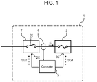
- Fig. 1 is a circuit block diagram of a power cutoff device in accordance with an exemplary embodiment.
- Power cutoff device 1 includes relay unit 2, cutoff unit 3, current detector 4, and controller 5.
- Relay unit 2 is connected in series with cutoff unit 3.
- Current detector 4 is configured to detect object current ID flowing through cutoff unit 3 in each of detection periods.
- Current detector 4 is connected to controller 5.
- Controller 5 is configured to control the opening and closing operations of relay unit 2 and cutoff unit 3.
- cutoff unit 3 Upon receiving cutoff signal SG1 transmitted from controller 5, cutoff unit 3 is switched from a connecting state to an irreversible cutoff state. Upon receiving cutoff signal SG2 transmitted from controller 5, relay unit 2 is switched from a connecting state to a cutoff state. Cutoff signals SG1 and SG2 are supplied when controller 5 determines that the changing rate of object current ID in a detection period is greater than changing-rate threshold CT.
- controller 5 determines that object current ID has e a large value at an early stage of a transition period in which object current ID flowing through relay unit 2 and cutoff unit 3 changes from a permissible value to a large value. Before object current ID has a large value, relay unit 2 and cutoff unit 3 are switched from the connecting state to the cutoff state.
- relay unit 2 and cutoff unit 3 allows relay unit 2 and cutoff unit 3 to be in the cutoff state at a stage before object current ID in relay unit 2 reaches an excessively large value, thus preventing an arc generated at a contact of relay unit 2, and preventing an incomplete cutoff state that results from the occurrence of the arc. Since object current ID is cut off before reaching a large value, relay unit 2 may not necessarily have a large size in order to ensure sufficient operation reliability of relay unit 2, and as a result, power cutoff device 1 has a small size.
- the conventional cutoff device described above requires a very large current to flow through it in order to blow the fuse and cut off electric power in a short time.
- the relay In order to operate a relay properly in a condition where a large current flows such that the fuse is blown out in a short time, the relay necessarily has a large current capacity. If a current larger than a threshold value flows through the relay in the case where the current capacity of the relay is small, the relay may not be in the cutoff state and continuously conductive due of an arc discharge occurring between contacts of the relay, hence damaging the relay. Consequently, the operation reliability of the cutoff device may be lowered. For this reason, it is inevitable that the size of the relay be large in order to improve the reliability of the cutoff operation of the cutoff device.
- power cutoff device 1 reduces its size, as described above.
- Fig. 2 is a circuit block diagram of vehicle 6 having power cutoff device 1 mounted thereto.
- Fig. 3 shows an operation characteristics of power cutoff device 1.
- Power cutoff device 1 is installed to in vehicle 6 which uses electric power for propulsion driving. Power cutoff device 1 is mounted to vehicle body 7 of vehicle 6. High voltage battery 8 and driving load 9 are also mounted to vehicle body 7. High voltage battery 8 is connected to input terminal 10 of power cutoff device 1. Driving load 9 is connected to output terminal 11 of power cutoff device 1 via junction box 12. Power cutoff device 1 is installed to vehicle 6, but power cutoff device 1 may constitutes a power cutoff system together with high voltage battery 8 and driving load 9.
- high voltage battery 8 is a secondary battery having a direct-current (DC) high voltage of about several hundred volts to about 1000 volts.
- Driving load 9 includes power converter 9A, such as an inverter, and driving motor 9B.
- Junction box 12 is configured to distribute electric power from high voltage battery 8 to other loads in addition to driving load 9 to allow electric power to be supplied thereto.
- Relay unit 2 includes switch 2S.
- Switch 2S is configured to be in a connecting state in which the switch is electrically conductive and a cutoff state in which the switch is electrically non-conductive.
- Relay unit 2 includes control terminal 2C.
- Switch 2S is in the connecting state upon not receiving cutoff signal SG2 at control terminal 2C.
- Switch 2S is in the cutoff state upon receiving cutoff signal SG2 at control terminal 2C.
- Cutoff unit 3 includes breaker 3A connected in series to switch 2S of relay unit 2.
- Breaker 3A is configured to be in a connecting state in which the breaker is electrically conductive and in an irreversible cutoff state in which the breaker is electrically non-conductive irreversibly.
- Cutoff unit 3 includes control terminal 3C.
- Breaker 3A is normally in the connecting state. Breaker 3A is in the irreversible cutoff state when cutoff signal SG1 is received at control terminal 3C.
- Current detector 4 is configured to detect object current ID flowing through breaker 3A of
- Relay unit 2 may include electromagnetic relay 2A including switch 2S implemented by a mechanical contact, and relay circuit 2B for turning on and off electromagnetic relay 2A.
- the relay may be implemented by a semiconductor switch in place of the electromagnetic relay.
- Cutoff unit 3 is continuously in the connecting state before vehicle 6 is started.
- Breaker 3A of cutoff unit 3 performs a cutoff operation in response to a cutoff signal received from outside like a pyro igniter. After that, the breaker in the cutoff operation is continuously in the irreversible cutoff state that does not return to the connecting state.
- Controller 5 may include cutoff circuit 3B for cutting off breaker 3A.
- cutoff circuit 3B receives cutoff signal SG1 emitted from controller 5 at control terminal 3C to ignite a pyrotechnic part of the pyro igniter of breaker 3A. Then, energy generated by igniting and exploding the pyrotechnic part of breaker 3A causes a conductive part of cutoff unit 3 to destruct, and causes cutoff unit 3 to be in the cutoff state.
- cutoff circuit 3B supplies redundant current to breaker 3A upon receiving cutoff signal SG1.
- cutoff unit 3 employs an active fuse. Or, cutoff unit 3 operates as an active fuse as a whole.
- Fig. 3 shows an operation characteristics of power cutoff device 1.
- the vertical axis represents object current ID flowing through breaker 3A of cutoff unit 3, and the horizontal axis represents time.
- Fig. 3 shows object current ID0 of power cutoff device 1 in accordance with the embodiment.
- Fig. 3 also shows object current ID1 of a comparative example of a power cutoff device configured to detect that object current ID exceeds overcurrent limit IT so as to cut off a cutoff unit thereof.
- Fig. 3 shows changing-rate threshold CT denoted by a straight dashed line.
- Overcurrent limit IT is set to a current that flows when short-circuit occurs in vehicle 6 or vehicle body 7.
- overcurrent limit IT may be set to a lower limit value of a current that flows when short-circuit occurs in vehicle 6 or vehicle body 7, particularly when short-circuit related to high voltage battery 8 occurs.
- Current detector 4 may be implemented by a Hall element or a shunt resistor as a current detecting element.
- Current detector 4 is configured to detect a current value of object current ID flowing through breaker 3A of cutoff unit 3 and switch 2S of relay unit 2, and to transmit to controller 5 an electric signal corresponding to the detected current value.
- current detector 4 is connected between relay unit 2 and cutoff unit 3.
- Current detector 4 may be connected between relay unit 2 and input terminal 10.
- current detector 4 may be connected between cutoff unit 3 and output terminal 11.
- steady value Ic is a pulsating flow
- overcurrent limit IT is a trigger for the cutoff operation of power cutoff device 1 when an abnormal current, such as a short-circuit current, flows through power cutoff device 1.
- Difference Ivn between the local maximum value and the local minimum value of the pulsating flow to have steady value Ic is much smaller than the difference between steady value Ic and overcurrent limit IT. The change of the pulsating current having steady value Ic from the local maximum value to the local minimum value occurs more slowly than the change of the current when a short-circuit current occurs.
- current detector 4 starts to detect object current ID and controller 5 starts calculations on object current ID.
- the detection of object current ID, the calculation on object current ID, and comparison and determination of the calculation results with changing-rate threshold CT are executed for each of plurality of detection periods each having a predetermined length ⁇ T.
- the controller converts the amount of change of value IDb of object current ID detected at timing Tb from value IDa of object current ID detected at timing Ta by calculation into changing rate CTab which is the amount of change of the object current per unit time over detection period PTab from timing Ta to timing Tb.
- the controller compares changing rate CTab with changing-rate threshold CT.
- the controller converts the amount of change of value IDc of object current ID detected at timing Tc from value IDb of object current ID by calculation into changing rate CTbc over detection period PTbc from timing Tb to timing Tc.
- the controller compares changing rate CTbc with changing-rate threshold CT.
- the controller converts the amount of change of value IDd of object current ID detected at timing Td from value IDc of object current ID by calculation into changing rate CTcd over detection period PTcd from timing Tb to timing Tc.
- the controller compares changing rate CTcd with changing-rate threshold CT.
- current detector 4 is configured to detect object current ID in each of plural detection periods PTab, PTbc, and PTcd.
- Current detector 4 is configured to detect plural values IDb and IDc of object current ID at different timings Tb and Tc in detection period PTbc, and to detect plural values IDc and IDd of object current ID at different timings Tc and Td in detection period PTcd.
- Controller 5 is configured to obtain changing rate CTbc based on the plural values IDb and IDc of object current ID and to obtain changing rate CTcd based on the plural values IDc and IDd.
- the plural detection periods PTab, PTbc, and PTcd may have lengths ⁇ T identical to one another, or may have lengths different from one another.
- controller 5 determines that changing rate CTab is smaller than changing-rate CT. Then, controller 5 does not transmit cutoff signal SG1 or cutoff signal SG2 but allows the steady state to continue. Thus, controller 5 causes switch 2S of relay unit 2 to be in the connecting state and causes cutoff unit 3 to be in the connecting state if controller 5 determines that changing rate CTab is not greater than changing-rate CT.
- changing-rate threshold CT utilized by controller 5 in performing comparison and determination may be set to an increasing rate of the object current from the local maximum value to the local minimum value, which is the amount of change per unit time, of the pulsating flow that normally occurs in steady value Ic.
- changing-rate threshold CT may be set to an increase rate that is the changing rate per unit time of steady value Ic in a short time in which a possible local minimum value of steady value Ic may appear.
- changing-rate threshold CT may be set to a value with a large allowance, the vale being obtained by multiplying the increase rate which is the amount of change per unit time by a constant greater than 1.
- changing-rate threshold CT is determined based on an increase rate that is the amount of change per unit time at the time when object current ID increases most steeply in the case where the vehicle operates in a normal condition. This configuration allows controller 5 to precisely and easily determine a steady state and an abnormal state in which a short-circuit occurs, which will be described below.
- Changing-rate CT may be previously stored in a memory or the like of controller 5 as a predetermined value.
- changing-rate threshold CT may be updated at appropriate timings from the value previously stored in a memory or the like of controller 5 based on the fluctuation of object current ID in a steady state.
- Fig. 4 is a block diagram of driving load 9 of vehicle 6 having power cutoff device 1 mounted thereto.
- Fig. 5 shows current 19 flowing through driving load 9.
- power converter 9A converts the DC voltage of high voltage battery 8 into alternating-current (AC) voltage V9F which drives driving motor 9B.
- AC alternating-current
- Power converter 9A includes upper arm switch 9C connected to a higher potential side and lower arm switch 9D connected to a lower potential side for power conversion.
- Power converter 9A further includes inductive component 9E existing in a conductor of power converter 9A.
- inductive component 9E is described as a component with a lumped constant. Exactly speaking, inductive component 9E is distributed over all of conductor parts including power cutoff device 1, such as conductor part 8A connecting power cutoff device 1 to high voltage battery 8, conductive path 14, and other conductor parts.
- driving motor 9B is connected to node 9J between upper arm switch 9C and lower arm switch 9D. Wound-wire part 9F of driving motor 9B is connected as a load in circuitry.
- AC voltage V9F supplied from power converter 9A to driving motor 9B does not actually exhibit smooth sine wave R1 shown in Fig. 5 , but exhibits an actual waveform with a continuous pulsation with repetitive rises and falls around sine wave R1.
- the rising period and the falling period in the pulsation are determined by the ratio of the on-time to the off-time of each of upper arm switch 9C and lower arm switch 9D.
- the on-time and the off-time of each of upper arm switch 9C and lower arm switch 9D are controlled according to, for example, a pulse width modulation (PWM) signal supplied from drive controller 15 installed to vehicle 6.
- PWM pulse width modulation
- V a voltage of high voltage battery 8
- L1 the total of inductances of wound-wire part 9F and inductive component 9E.
- the inductance of wound-wire part 9F is 10 mH level while the inductance of inductive component 9E is 10 ⁇ H level. Inductive component 9E is thus negligible in the calculation.
- V the voltage of high voltage battery 8
- changing-rate threshold CT may be set to about one-tenth of changing rate CT1 in the case where only inductive component 9E is the load, about 5 A/ ⁇ sec in the case of the above-described example.
- voltage VI may be set to about 60 V as an exemplary value which is considered as the upper limit DC voltage which does not adversely affect human bodies in a short time
- changing-rate threshold CT may be set to a value obtained as V1/L2.
- inductance of inductive component 9E is 10 ⁇ H for convenience in calculation
- the inductance is of course preferably set to an appropriate value.
- changing-rate threshold CT may be determined based on the inductance of inductive component 9E.
- Current detector 4 is preferably connected between relay unit 2 and input terminal 10. This configuration broadens a target area in which a short-circuit may occur, and improves the operation reliability of power cutoff device 1.
- object current ID continuously increase rapidly from steady value Ic to abnormal current Ia at a linear slope.
- object current ID changes from value IDb at timing Tb to value IDc at timing Tc.
- object current ID significantly increases from timing Tb, which is in a steady state, to timing Tc, which is in an abnormal state.
- controller 5 compares changing rate CTbc with changing-rate threshold CT.
- Controller 5 determines that changing rate CTbc is greater than changing-rate threshold CT. Then, controller 5 transmits cutoff signal SG1 to cutoff unit 3 and transmits cutoff signal SG2 to relay unit 2.
- cutoff unit 3 receiving cutoff signal SG1
- breaker 3A is switched from the connecting state to the irreversible cutoff state.
- switch 2S is switched from the connecting state to the cutoff state.
- timing T2 at which time power cutoff device 1 cuts off the discharge path from high voltage battery 8.
- timing Tc may be substantially simultaneous to timing T2. Strictly speaking, timing T2 is after timing Tc due to a processing time of controller 5 and the cutoff completion speed of cutoff unit 3.
- controller 5 Unless controller 5 determines that changing rate CTbc is greater than changing-rate threshold CT, controller 5 transmits neither cutoff signal SG1 nor cutoff signal SG2.
- controller 5 determines that object current ID later becomes a large value resulting in an overcurrent state, at an early stage of the transition period in which object current ID flowing through relay unit 2 and cutoff unit 3 changes from a permissible value to a large value, that is, at an early stage in which the value of object current ID is small. Before object current ID becomes a large value, relay unit 2 and cutoff unit 3 are switched from the connecting state to the cutoff state.
- This configuration allows relay unit 2 and cutoff unit 3 to be in the cutoff state at a stage before object current ID at relay unit 2 reaches an excessively large value, thus preventing the occurrence of an arc produced at a contact of switch 2S of relay unit 2 and the occurrence of an incomplete cutoff state resulting from the occurrence of the arc. Since object current ID is cut off before reaching a large value, short-circuit withstand current IS nay not necessarily set to be a large value in order to ensure sufficient operation reliability of relay unit 2. Accordingly, the size of relay unit 2 may not necessarily be increased, and reduces the size of power cutoff device 1 accordingly.
- Fig. 3 shows object current ID1 of the comparative example of the power cutoff device which is configured to detect that object current ID1 exceeds overcurrent limit IT, and then, cause the cutoff unit to be in the cutoff state.
- object current ID1 object current ID1 is detected to exceed overcurrent limit IT and the cutoff operation of the cutoff unit is started at timing Te, and the cutoff is completed at timing T3.
- object current ID1 exceeds overcurrent limit IT and becomes close to short-circuit withstand current IS at timing Tz. Therefore, in order to ensure sufficient operation reliability of relay unit 2, it is necessary to set short-circuit withstand current IS to a large value, and to increase the size of relay unit 2 accordingly.
- power cutoff device 1 of this example predicts and determines at timing Td that overcurrent of object current ID occurs at a time later than timing Td without detecting that object current ID reaches overcurrent limit IT. Since current detector 4 and controller 5 detect and determine that changing rate CTbc of object current ID becomes greater than changing-rate threshold CT, controller 5 is able to determine, at timing Td before timing Tz, that object current ID is going to exceed overcurrent limit IT at a time after timing Td.
- cutoff unit 3 may be preferably switched from the connecting state to the irreversible cutoff state at first, and then, relay unit 2 is switched from the connecting state to the cutoff state. Cutoff signals SG1 and SG2 may be transmitted simultaneously, or cutoff signal SG1 may be transmitted before cutoff signal SG2 is transmitted.
- breaker 3A of cutoff unit 3 may be preferably implemented by an active fuse, such as a pyro igniter, which has a faster cutoff speed than relay unit 2.
- Fig. 6 shows other operation characteristics of power cutoff device 1 in accordance with the embodiment.
- items identical to those of Fig. 3 are denoted by the same reference numerals.
- changing rate CTcd of object current ID may be utilized in addition to changing rate CTbc described above.
- controller 5 determines that changing rate CTbc of object current ID in detection period PTbc from timing Tb to timing Tc becomes greater than changing-rate threshold CT, and thereby, determines that object current ID is going to be a large value resulting in an overcurrent state later.
- current detector 4 detects value IDd of object current ID at timing Td.
- controller 5 determines that object current ID is going to be a large value resulting in an overcurrent state later.
- controller 5 determines successively that object current ID is going to be a large value resulting in an overcurrent state later, controller 5 transmits cutoff signal SG1 and cutoff signal SG2. Then, at timing T2 immediately after timing Td, relay unit 2 is switched from the connecting state to the cutoff state and cutoff unit 3 is switched from the connecting state to the irreversible cutoff state, so that power cutoff device 1 cuts off the discharge path from high voltage battery 8.
- controller 5 causes switch 2S of relay unit 2 to be in the connecting state and maintains cutoff unit 3 in the connecting state if determining that at least one of changing rate CTbc and changing rate and CTcd is not greater than changing-rate threshold CT.
- Controller 5 determines whether or not changing rate CTbc over detection period PTbc and changing rate CTcd over detection period PTcd which is consecutive to detection period PTbc are greater than changing-rate threshold CT.
- Controller 5 may use the rates of change over further subsequent detection periods to compare them with changing-rate threshold CT to make a determination. Controller 5 may successively determine that all the rates of change over plural detection periods are greater than changing-rate threshold CT, and thereby, controller 5 may determine that object current ID is going to be a large value resulting in an overcurrent state later, and may switch relay unit 2 and cutoff unit 3 to the cutoff state.
- controller 5 determines successively that object current ID is going to be a large value resulting in an overcurrent state later, controller 5 transmits cutoff signal SG1 and cutoff signal SG2. In response to the signals, relay unit 2 is switched to the cutoff state, and cutoff unit 3 is switched to the irreversible cutoff state.
- Controller 5 causes relay unit 2 to be in the connecting state and causes cutoff unit 3 to be in the connecting state if controller 5 determines that changing rate CTbc is not greater than changing-rate threshold CT or determines that changing rate CTcd is not greater than changing rate CTbc.
- both of rates of change CTbc and CTcd are greater than changing-rate threshold CT, as shown as the slope of the linear lines.
- Changing rate CTcd may be obtained as (IDc-IDb)/ ⁇ T by detection of object current ID and calculation performed by controller 5.
- Timing T1 at which object current ID starts to rapidly increase from steady value Ic to abnormal current Ia as mentioned earlier does not necessarily agree with timings Ta to Te, ... at which object current ID is detected for each predetermined period ⁇ T.
- timing Tc that is the starting point of the current value for performing calculation agrees with timing Tc that is one of the detection timings that are set for each predetermined period ⁇ T.
- changing rate CTbc is smaller than changing rate CTcd even when object current ID is properly detected and calculation is properly carried out by controller 5.
- the fact that changing rate CTbc is greater than changing rate CTcd may indicate that an erroneous determination occurs due to an accidental detection error or a calculation error.
- controller 5 may use the fact that changing rate CTbc is smaller than changing rate CTcd as a criterion to determine that object current ID is going to be a large value resulting in an overcurrent state later. This operation prevents erroneous determinations resulting from accidental detection errors and calculation errors, and increases the operation reliability of power cutoff device 1.
- Controller 5 utilizes changing rate CTbc over detection period PTbc and changing rate CTcd over detection period PTcd consecutive to detection period PTbc to make the determination. Controller 5 may utilize changing rate CTde over detection period PTde consecutive to detection period PTcd, or the rates of change over further subsequent detection periods to make the determination. That is, controller 5 may successively determine that changing rate CTde and the subsequent rates of change over plural subsequent detection periods are greater than changing rate CTbc, and thereby, controller 5 may determine that object current ID is going to be a large value resulting in an overcurrent state, and transmit cutoff signals SG1 and SG2 so as to switch relay unit 2 from the connecting state to the cutoff state and to switch cutoff unit 3 from the connecting state to the irreversible cutoff state.
- controller 5 determines that object current ID is going to be a large value resulting in an overcurrent state later based on the fact that changing rate CTbc and changing rate CTcd successively become greater than changing-rate threshold CT, and the operation in which controller 5 determines that object current ID is going to be a large value resulting in an overcurrent state later based on the fact that changing rate CTbc is smaller than changing rate CTcd.
- controller 5 may transmit cutoff signals SG1 and SG2, switch relay unit 2 from the connecting state to the cutoff state, and switch cutoff unit 3 from the connecting state to the irreversible cutoff state.
- controller 5 does not transmit cutoff signals SG1 and SG2 and maintains relay unit 2 and cutoff unit 3 in the connecting state. This configuration prevents erroneous determinations resulting from accidental detection errors and calculation errors, consequently improving the operation reliability of power cutoff device 1.
Landscapes
- Engineering & Computer Science (AREA)
- Power Engineering (AREA)
- Transportation (AREA)
- Mechanical Engineering (AREA)
- Life Sciences & Earth Sciences (AREA)
- Sustainable Development (AREA)
- Sustainable Energy (AREA)
- Emergency Protection Circuit Devices (AREA)
- Electric Propulsion And Braking For Vehicles (AREA)
Applications Claiming Priority (2)
| Application Number | Priority Date | Filing Date | Title |
|---|---|---|---|
| JP2019131530 | 2019-07-17 | ||
| PCT/JP2020/019155 WO2021010007A1 (fr) | 2019-07-17 | 2020-05-13 | Dispositif de coupure de puissance |
Publications (3)
| Publication Number | Publication Date |
|---|---|
| EP4002620A1 true EP4002620A1 (fr) | 2022-05-25 |
| EP4002620A4 EP4002620A4 (fr) | 2022-09-14 |
| EP4002620B1 EP4002620B1 (fr) | 2024-10-30 |
Family
ID=74210408
Family Applications (1)
| Application Number | Title | Priority Date | Filing Date |
|---|---|---|---|
| EP20839814.9A Active EP4002620B1 (fr) | 2019-07-17 | 2020-05-13 | Dispositif de coupure de puissance |
Country Status (5)
| Country | Link |
|---|---|
| US (1) | US12194866B2 (fr) |
| EP (1) | EP4002620B1 (fr) |
| JP (1) | JP7565486B2 (fr) |
| CN (1) | CN114128070B (fr) |
| WO (1) | WO2021010007A1 (fr) |
Families Citing this family (7)
| Publication number | Priority date | Publication date | Assignee | Title |
|---|---|---|---|---|
| JP7529140B2 (ja) * | 2021-03-10 | 2024-08-06 | 株式会社オートネットワーク技術研究所 | 遮断制御装置 |
| CN117280556A (zh) * | 2021-05-25 | 2023-12-22 | 株式会社自动网络技术研究所 | 车载用控制装置 |
| WO2023242988A1 (fr) * | 2022-06-15 | 2023-12-21 | 株式会社オートネットワーク技術研究所 | Dispositif de commande d'interruption |
| CN115189329A (zh) * | 2022-07-06 | 2022-10-14 | 中国华能集团清洁能源技术研究院有限公司 | 断路器的控制系统和基于断路器的控制系统的控制方法 |
| CN120152868A (zh) * | 2022-11-08 | 2025-06-13 | 株式会社自动网络技术研究所 | 车辆用切断控制装置 |
| JP7577722B2 (ja) * | 2022-11-30 | 2024-11-05 | 本田技研工業株式会社 | 蓄電システム |
| CN117630727B (zh) * | 2023-12-06 | 2024-08-20 | 北京市中环博业环境工程技术有限公司 | 静电除尘电源无火花放电监控方法、装置、设备和介质 |
Family Cites Families (26)
| Publication number | Priority date | Publication date | Assignee | Title |
|---|---|---|---|---|
| ZA941138B (en) * | 1993-02-26 | 1994-08-29 | Westinghouse Electric Corp | Circuit breaker responsive to repeated in-rush currents produced by a sputtering arc fault. |
| JPH08251907A (ja) * | 1995-03-08 | 1996-09-27 | Toshiba Corp | 半導体遮断器 |
| JP3981893B2 (ja) * | 1996-05-22 | 2007-09-26 | ソニー株式会社 | バッテリパック、充電器、および充電システム、並びに充電方法 |
| DE19835781C2 (de) * | 1998-08-07 | 2002-10-24 | Daimler Chrysler Ag | Verfahren und Vorrichtung zur Auslösung einer Sicherung für elektrische Leiter in einem Kraftfahrzeug |
| JP2007110844A (ja) * | 2005-10-14 | 2007-04-26 | C Tekku:Kk | 直流電源遮断装置 |
| KR100804518B1 (ko) * | 2007-07-18 | 2008-02-20 | 엠티엔시 (주) | 누설 전류를 2단계로 감지하여 오동작을 방지하는 누전차단 방법 및 그 장치 |
| JP2011223655A (ja) * | 2010-04-05 | 2011-11-04 | Toyota Motor Corp | 車両の電源装置 |
| KR101037669B1 (ko) * | 2010-05-31 | 2011-05-30 | 주식회사 담솔 | 콘센트의 대기전력차단장치 |
| JP5683372B2 (ja) * | 2011-04-27 | 2015-03-11 | デクセリアルズ株式会社 | 充放電制御装置、バッテリパック、電気機器、及び、充放電制御方法 |
| JP5903673B2 (ja) * | 2012-03-05 | 2016-04-13 | パナソニックIpマネジメント株式会社 | 2線式負荷制御装置 |
| JP6234127B2 (ja) * | 2012-10-11 | 2017-11-22 | 株式会社Gsユアサ | 蓄電装置 |
| CN104833911A (zh) * | 2014-05-21 | 2015-08-12 | 北汽福田汽车股份有限公司 | 动力电池中的继电器的故障判断方法和装置 |
| JP2016127769A (ja) * | 2015-01-08 | 2016-07-11 | 三洋電機株式会社 | 電池パック |
| WO2016185711A1 (fr) * | 2015-05-21 | 2016-11-24 | 日本電気株式会社 | Dispositif de surveillance de batterie de stockage |
| JP6439597B2 (ja) * | 2015-06-09 | 2018-12-19 | 株式会社デンソー | 電力変換装置 |
| JP6421095B2 (ja) * | 2015-08-05 | 2018-11-07 | 株式会社オートネットワーク技術研究所 | 中継機 |
| CN106483846B (zh) * | 2015-09-01 | 2019-12-13 | 苏州宝时得电动工具有限公司 | 电动工具的控制方法及执行该控制方法的电动工具 |
| DE102016204287A1 (de) * | 2016-03-16 | 2017-09-21 | Bayerische Motoren Werke Aktiengesellschaft | Dc-überstromschutzvorrichtung |
| JP6620674B2 (ja) * | 2016-05-26 | 2019-12-18 | 株式会社オートネットワーク技術研究所 | 給電制御装置、給電制御方法及びコンピュータプログラム |
| US10025365B2 (en) * | 2016-06-23 | 2018-07-17 | Hewlett Packard Enterprise Development Lp | Power courses based on current changes |
| KR101996510B1 (ko) * | 2017-02-22 | 2019-07-04 | 한양대학교 에리카산학협력단 | Dc 그리드용 고장 전류 제한기 및 그 제어방법 |
| JP6426783B2 (ja) * | 2017-03-14 | 2018-11-21 | ファナック株式会社 | パワー素子の異常検知機能を備えたモータ駆動装置 |
| EP3379725A1 (fr) * | 2017-03-23 | 2018-09-26 | Siemens Aktiengesellschaft | Procédé de commande d'un commutateur à courant continu, commutateur à courant continu et système de tension continue |
| CN107677930B (zh) * | 2017-09-15 | 2021-02-12 | 漳州科华技术有限责任公司 | 一种ups直流母线熔断器状态检测方法及装置 |
| US11070049B2 (en) * | 2017-11-08 | 2021-07-20 | Eaton Intelligent Power Limited | System, method, and apparatus for power distribution in an electric mobile application using a combined breaker and relay |
| CN108001482B (zh) * | 2017-11-28 | 2020-06-30 | 中车大连机车车辆有限公司 | 电气车辆分段连续式地面供电系统及方法 |
-
2020
- 2020-05-13 WO PCT/JP2020/019155 patent/WO2021010007A1/fr not_active Ceased
- 2020-05-13 CN CN202080050766.4A patent/CN114128070B/zh active Active
- 2020-05-13 JP JP2021532698A patent/JP7565486B2/ja active Active
- 2020-05-13 EP EP20839814.9A patent/EP4002620B1/fr active Active
- 2020-05-13 US US17/618,799 patent/US12194866B2/en active Active
Also Published As
| Publication number | Publication date |
|---|---|
| JP7565486B2 (ja) | 2024-10-11 |
| CN114128070B (zh) | 2024-10-11 |
| JPWO2021010007A1 (fr) | 2021-01-21 |
| WO2021010007A1 (fr) | 2021-01-21 |
| EP4002620A4 (fr) | 2022-09-14 |
| EP4002620B1 (fr) | 2024-10-30 |
| US12194866B2 (en) | 2025-01-14 |
| CN114128070A (zh) | 2022-03-01 |
| US20220250481A1 (en) | 2022-08-11 |
Similar Documents
| Publication | Publication Date | Title |
|---|---|---|
| EP4002620B1 (fr) | Dispositif de coupure de puissance | |
| CN100417549C (zh) | 蓄电池安全开关 | |
| CN101814720B (zh) | 电动车辆逆变器设备及其保护方法 | |
| US9802562B2 (en) | Automotive power unit | |
| US4222030A (en) | Electric control circuit for safety apparatus in automotive vehicles | |
| US11059439B2 (en) | In-vehicle power supply device | |
| JP5414818B2 (ja) | 電気自動車用電力変換装置 | |
| US11396235B2 (en) | Traction network and method for operating a traction network of an electrically-driven transportation vehicle in the event of a short circuit | |
| EP3820009B1 (fr) | Système de protection | |
| CN1649756A (zh) | 车辆的控制器 | |
| US20240246420A1 (en) | Cutoff device for vehicle and cutoff method | |
| EP3878697A1 (fr) | Système de coupure de courant | |
| US12394975B2 (en) | Interruption device | |
| US20220144095A1 (en) | Battery system | |
| US4207503A (en) | Battery supplied motor current control system with safety circuit | |
| US11059371B2 (en) | On-vehicle power supply device and vehicle having on-vehicle power supply device mounted thereon | |
| JP2000504551A (ja) | 自動車の電子システムにおける電圧コントローラの配線 | |
| CN106300942B (zh) | 用于使逆变器的高电压电路放电的组件及方法 | |
| US20240283446A1 (en) | Switch drive device | |
| CN117043013A (zh) | 切断控制装置 | |
| US20250357746A1 (en) | Cutoff control device | |
| EP3904143B1 (fr) | Dispositif de conversion d'alimentation électrique | |
| WO2003057536A1 (fr) | Appareil d'alimentation electrique destine a prevenir les incendies sur les vehicules | |
| US12401186B2 (en) | Electronic control system and electronic control device | |
| US20260116201A1 (en) | Power supply device for moving object |
Legal Events
| Date | Code | Title | Description |
|---|---|---|---|
| STAA | Information on the status of an ep patent application or granted ep patent |
Free format text: STATUS: THE INTERNATIONAL PUBLICATION HAS BEEN MADE |
|
| PUAI | Public reference made under article 153(3) epc to a published international application that has entered the european phase |
Free format text: ORIGINAL CODE: 0009012 |
|
| STAA | Information on the status of an ep patent application or granted ep patent |
Free format text: STATUS: REQUEST FOR EXAMINATION WAS MADE |
|
| 17P | Request for examination filed |
Effective date: 20211213 |
|
| AK | Designated contracting states |
Kind code of ref document: A1 Designated state(s): AL AT BE BG CH CY CZ DE DK EE ES FI FR GB GR HR HU IE IS IT LI LT LU LV MC MK MT NL NO PL PT RO RS SE SI SK SM TR |
|
| A4 | Supplementary search report drawn up and despatched |
Effective date: 20220811 |
|
| RIC1 | Information provided on ipc code assigned before grant |
Ipc: H02H 3/44 20060101ALI20220805BHEP Ipc: B60L 3/04 20060101ALI20220805BHEP Ipc: H02H 3/093 20060101AFI20220805BHEP |
|
| DAV | Request for validation of the european patent (deleted) | ||
| DAX | Request for extension of the european patent (deleted) | ||
| REG | Reference to a national code |
Ref legal event code: R079 Ref country code: DE Ref legal event code: R079 Ref document number: 602020040474 Country of ref document: DE Free format text: PREVIOUS MAIN CLASS: H02H0003080000 Ipc: H02H0003093000 |
|
| GRAP | Despatch of communication of intention to grant a patent |
Free format text: ORIGINAL CODE: EPIDOSNIGR1 |
|
| STAA | Information on the status of an ep patent application or granted ep patent |
Free format text: STATUS: GRANT OF PATENT IS INTENDED |
|
| RIC1 | Information provided on ipc code assigned before grant |
Ipc: H02H 3/44 20060101ALI20240430BHEP Ipc: B60L 3/04 20060101ALI20240430BHEP Ipc: H02H 3/093 20060101AFI20240430BHEP |
|
| INTG | Intention to grant announced |
Effective date: 20240527 |
|
| GRAS | Grant fee paid |
Free format text: ORIGINAL CODE: EPIDOSNIGR3 |
|
| GRAA | (expected) grant |
Free format text: ORIGINAL CODE: 0009210 |
|
| STAA | Information on the status of an ep patent application or granted ep patent |
Free format text: STATUS: THE PATENT HAS BEEN GRANTED |
|
| AK | Designated contracting states |
Kind code of ref document: B1 Designated state(s): AL AT BE BG CH CY CZ DE DK EE ES FI FR GB GR HR HU IE IS IT LI LT LU LV MC MK MT NL NO PL PT RO RS SE SI SK SM TR |
|
| REG | Reference to a national code |
Ref country code: GB Ref legal event code: FG4D |
|
| REG | Reference to a national code |
Ref country code: CH Ref legal event code: EP |
|
| REG | Reference to a national code |
Ref country code: IE Ref legal event code: FG4D |
|
| REG | Reference to a national code |
Ref country code: DE Ref legal event code: R096 Ref document number: 602020040474 Country of ref document: DE |
|
| REG | Reference to a national code |
Ref country code: LT Ref legal event code: MG9D |
|
| REG | Reference to a national code |
Ref country code: NL Ref legal event code: MP Effective date: 20241030 |
|
| PG25 | Lapsed in a contracting state [announced via postgrant information from national office to epo] |
Ref country code: PT Free format text: LAPSE BECAUSE OF FAILURE TO SUBMIT A TRANSLATION OF THE DESCRIPTION OR TO PAY THE FEE WITHIN THE PRESCRIBED TIME-LIMIT Effective date: 20250228 Ref country code: IS Free format text: LAPSE BECAUSE OF FAILURE TO SUBMIT A TRANSLATION OF THE DESCRIPTION OR TO PAY THE FEE WITHIN THE PRESCRIBED TIME-LIMIT Effective date: 20250228 Ref country code: HR Free format text: LAPSE BECAUSE OF FAILURE TO SUBMIT A TRANSLATION OF THE DESCRIPTION OR TO PAY THE FEE WITHIN THE PRESCRIBED TIME-LIMIT Effective date: 20241030 |
|
| PG25 | Lapsed in a contracting state [announced via postgrant information from national office to epo] |
Ref country code: FI Free format text: LAPSE BECAUSE OF FAILURE TO SUBMIT A TRANSLATION OF THE DESCRIPTION OR TO PAY THE FEE WITHIN THE PRESCRIBED TIME-LIMIT Effective date: 20241030 Ref country code: NL Free format text: LAPSE BECAUSE OF FAILURE TO SUBMIT A TRANSLATION OF THE DESCRIPTION OR TO PAY THE FEE WITHIN THE PRESCRIBED TIME-LIMIT Effective date: 20241030 |
|
| REG | Reference to a national code |
Ref country code: AT Ref legal event code: MK05 Ref document number: 1737881 Country of ref document: AT Kind code of ref document: T Effective date: 20241030 |
|
| PG25 | Lapsed in a contracting state [announced via postgrant information from national office to epo] |
Ref country code: BG Free format text: LAPSE BECAUSE OF FAILURE TO SUBMIT A TRANSLATION OF THE DESCRIPTION OR TO PAY THE FEE WITHIN THE PRESCRIBED TIME-LIMIT Effective date: 20241030 |
|
| PG25 | Lapsed in a contracting state [announced via postgrant information from national office to epo] |
Ref country code: ES Free format text: LAPSE BECAUSE OF FAILURE TO SUBMIT A TRANSLATION OF THE DESCRIPTION OR TO PAY THE FEE WITHIN THE PRESCRIBED TIME-LIMIT Effective date: 20241030 |
|
| PG25 | Lapsed in a contracting state [announced via postgrant information from national office to epo] |
Ref country code: NO Free format text: LAPSE BECAUSE OF FAILURE TO SUBMIT A TRANSLATION OF THE DESCRIPTION OR TO PAY THE FEE WITHIN THE PRESCRIBED TIME-LIMIT Effective date: 20250130 |
|
| PG25 | Lapsed in a contracting state [announced via postgrant information from national office to epo] |
Ref country code: LV Free format text: LAPSE BECAUSE OF FAILURE TO SUBMIT A TRANSLATION OF THE DESCRIPTION OR TO PAY THE FEE WITHIN THE PRESCRIBED TIME-LIMIT Effective date: 20241030 Ref country code: AT Free format text: LAPSE BECAUSE OF FAILURE TO SUBMIT A TRANSLATION OF THE DESCRIPTION OR TO PAY THE FEE WITHIN THE PRESCRIBED TIME-LIMIT Effective date: 20241030 Ref country code: GR Free format text: LAPSE BECAUSE OF FAILURE TO SUBMIT A TRANSLATION OF THE DESCRIPTION OR TO PAY THE FEE WITHIN THE PRESCRIBED TIME-LIMIT Effective date: 20250131 |
|
| PG25 | Lapsed in a contracting state [announced via postgrant information from national office to epo] |
Ref country code: PL Free format text: LAPSE BECAUSE OF FAILURE TO SUBMIT A TRANSLATION OF THE DESCRIPTION OR TO PAY THE FEE WITHIN THE PRESCRIBED TIME-LIMIT Effective date: 20241030 |
|
| PG25 | Lapsed in a contracting state [announced via postgrant information from national office to epo] |
Ref country code: RS Free format text: LAPSE BECAUSE OF FAILURE TO SUBMIT A TRANSLATION OF THE DESCRIPTION OR TO PAY THE FEE WITHIN THE PRESCRIBED TIME-LIMIT Effective date: 20250130 |
|
| PG25 | Lapsed in a contracting state [announced via postgrant information from national office to epo] |
Ref country code: SM Free format text: LAPSE BECAUSE OF FAILURE TO SUBMIT A TRANSLATION OF THE DESCRIPTION OR TO PAY THE FEE WITHIN THE PRESCRIBED TIME-LIMIT Effective date: 20241030 |
|
| PGFP | Annual fee paid to national office [announced via postgrant information from national office to epo] |
Ref country code: DE Payment date: 20250521 Year of fee payment: 6 |
|
| PG25 | Lapsed in a contracting state [announced via postgrant information from national office to epo] |
Ref country code: DK Free format text: LAPSE BECAUSE OF FAILURE TO SUBMIT A TRANSLATION OF THE DESCRIPTION OR TO PAY THE FEE WITHIN THE PRESCRIBED TIME-LIMIT Effective date: 20241030 |
|
| PG25 | Lapsed in a contracting state [announced via postgrant information from national office to epo] |
Ref country code: EE Free format text: LAPSE BECAUSE OF FAILURE TO SUBMIT A TRANSLATION OF THE DESCRIPTION OR TO PAY THE FEE WITHIN THE PRESCRIBED TIME-LIMIT Effective date: 20241030 |
|
| PG25 | Lapsed in a contracting state [announced via postgrant information from national office to epo] |
Ref country code: RO Free format text: LAPSE BECAUSE OF FAILURE TO SUBMIT A TRANSLATION OF THE DESCRIPTION OR TO PAY THE FEE WITHIN THE PRESCRIBED TIME-LIMIT Effective date: 20241030 |
|
| PG25 | Lapsed in a contracting state [announced via postgrant information from national office to epo] |
Ref country code: SK Free format text: LAPSE BECAUSE OF FAILURE TO SUBMIT A TRANSLATION OF THE DESCRIPTION OR TO PAY THE FEE WITHIN THE PRESCRIBED TIME-LIMIT Effective date: 20241030 |
|
| PG25 | Lapsed in a contracting state [announced via postgrant information from national office to epo] |
Ref country code: CZ Free format text: LAPSE BECAUSE OF FAILURE TO SUBMIT A TRANSLATION OF THE DESCRIPTION OR TO PAY THE FEE WITHIN THE PRESCRIBED TIME-LIMIT Effective date: 20241030 |
|
| PG25 | Lapsed in a contracting state [announced via postgrant information from national office to epo] |
Ref country code: IT Free format text: LAPSE BECAUSE OF FAILURE TO SUBMIT A TRANSLATION OF THE DESCRIPTION OR TO PAY THE FEE WITHIN THE PRESCRIBED TIME-LIMIT Effective date: 20241030 |
|
| REG | Reference to a national code |
Ref country code: DE Ref legal event code: R097 Ref document number: 602020040474 Country of ref document: DE |
|
| PLBE | No opposition filed within time limit |
Free format text: ORIGINAL CODE: 0009261 |
|
| STAA | Information on the status of an ep patent application or granted ep patent |
Free format text: STATUS: NO OPPOSITION FILED WITHIN TIME LIMIT |
|
| PG25 | Lapsed in a contracting state [announced via postgrant information from national office to epo] |
Ref country code: SE Free format text: LAPSE BECAUSE OF FAILURE TO SUBMIT A TRANSLATION OF THE DESCRIPTION OR TO PAY THE FEE WITHIN THE PRESCRIBED TIME-LIMIT Effective date: 20241030 |
|
| 26N | No opposition filed |
Effective date: 20250731 |
|
| REG | Reference to a national code |
Ref country code: CH Ref legal event code: H13 Free format text: ST27 STATUS EVENT CODE: U-0-0-H10-H13 (AS PROVIDED BY THE NATIONAL OFFICE) Effective date: 20251223 |
|
| PG25 | Lapsed in a contracting state [announced via postgrant information from national office to epo] |
Ref country code: LU Free format text: LAPSE BECAUSE OF NON-PAYMENT OF DUE FEES Effective date: 20250513 |
|
| PG25 | Lapsed in a contracting state [announced via postgrant information from national office to epo] |
Ref country code: CH Free format text: LAPSE BECAUSE OF NON-PAYMENT OF DUE FEES Effective date: 20250531 |
|
| GBPC | Gb: european patent ceased through non-payment of renewal fee |
Effective date: 20250513 |
|
| REG | Reference to a national code |
Ref country code: BE Ref legal event code: MM Effective date: 20250531 |
|
| PG25 | Lapsed in a contracting state [announced via postgrant information from national office to epo] |
Ref country code: MC Free format text: LAPSE BECAUSE OF FAILURE TO SUBMIT A TRANSLATION OF THE DESCRIPTION OR TO PAY THE FEE WITHIN THE PRESCRIBED TIME-LIMIT Effective date: 20241030 |
|
| PG25 | Lapsed in a contracting state [announced via postgrant information from national office to epo] |
Ref country code: GB Free format text: LAPSE BECAUSE OF NON-PAYMENT OF DUE FEES Effective date: 20250513 |
|
| PG25 | Lapsed in a contracting state [announced via postgrant information from national office to epo] |
Ref country code: IE Free format text: LAPSE BECAUSE OF NON-PAYMENT OF DUE FEES Effective date: 20250513 |
|
| PG25 | Lapsed in a contracting state [announced via postgrant information from national office to epo] |
Ref country code: BE Free format text: LAPSE BECAUSE OF NON-PAYMENT OF DUE FEES Effective date: 20250531 |
|
| PG25 | Lapsed in a contracting state [announced via postgrant information from national office to epo] |
Ref country code: FR Free format text: LAPSE BECAUSE OF NON-PAYMENT OF DUE FEES Effective date: 20250531 |