EP4002968A1 - Onduleur et son procédé de fabrication - Google Patents
Onduleur et son procédé de fabrication Download PDFInfo
- Publication number
- EP4002968A1 EP4002968A1 EP21205139.5A EP21205139A EP4002968A1 EP 4002968 A1 EP4002968 A1 EP 4002968A1 EP 21205139 A EP21205139 A EP 21205139A EP 4002968 A1 EP4002968 A1 EP 4002968A1
- Authority
- EP
- European Patent Office
- Prior art keywords
- converter
- cover
- housing part
- circuit board
- heat sink
- Prior art date
- Legal status (The legal status is an assumption and is not a legal conclusion. Google has not performed a legal analysis and makes no representation as to the accuracy of the status listed.)
- Granted
Links
Images
Classifications
-
- H—ELECTRICITY
- H05—ELECTRIC TECHNIQUES NOT OTHERWISE PROVIDED FOR
- H05K—PRINTED CIRCUITS; CASINGS OR CONSTRUCTIONAL DETAILS OF ELECTRIC APPARATUS; MANUFACTURE OF ASSEMBLAGES OF ELECTRICAL COMPONENTS
- H05K7/00—Constructional details common to different types of electric apparatus
- H05K7/20—Modifications to facilitate cooling, ventilating, or heating
- H05K7/2089—Modifications to facilitate cooling, ventilating, or heating for power electronics, e.g. for inverters for controlling motor
- H05K7/209—Heat transfer by conduction from internal heat source to heat radiating structure
-
- H—ELECTRICITY
- H05—ELECTRIC TECHNIQUES NOT OTHERWISE PROVIDED FOR
- H05K—PRINTED CIRCUITS; CASINGS OR CONSTRUCTIONAL DETAILS OF ELECTRIC APPARATUS; MANUFACTURE OF ASSEMBLAGES OF ELECTRICAL COMPONENTS
- H05K7/00—Constructional details common to different types of electric apparatus
- H05K7/14—Mounting supporting structure in casing or on frame or rack
- H05K7/1422—Printed circuit boards receptacles, e.g. stacked structures, electronic circuit modules or box like frames
- H05K7/1427—Housings
- H05K7/1432—Housings specially adapted for power drive units or power converters
- H05K7/14322—Housings specially adapted for power drive units or power converters wherein the control and power circuits of a power converter are arranged within the same casing
Definitions
- the invention relates to a converter, in particular a multi-phase three-phase converter, with a DC link and a power module having at least one power semiconductor, and a method for producing the converter.
- Multi-phase converters for example three-phase inverters or frequency converters, are used to feed multi-phase electrical drive machines from a DC voltage source.
- Such converters are used, for example, as frequency converters, which control a traction motor, for example an asynchronous motor, of an electrically driven vehicle, for example an industrial truck, from a DC voltage source.
- the DC voltage can be provided from a battery or a generator as a DC voltage source.
- a DC voltage generator or a three-phase current generator can be used as a generator, the three-phase current generated from which is rectified in a rectifier.
- Level on another board of the DC link with the other components of the converter, such as the smoothing capacitors in particular, are arranged.
- the power current connections or busbars directly down to the power semiconductors, in particular power transistors, through cutouts in this board in the second level, for example through screw bolts or pressure sleeves that lead to a lower, first board with the Power transistors, which is arranged on the heat sink, are passed.
- busbars also makes it possible to control the formation of electromagnetic fields within the converter housing to a certain extent.
- current sensors are required to control the converter, which record the currents flowing in the power current connections.
- current sensor cores which, as a soft magnetic material, for example laminated cores, enclose the current conductor and have a gap.
- a magnetic sensor, in particular a Hall sensor, is then arranged in this gap, via which the flowing currents can be detected indirectly via the magnetic fields that are formed.
- a disadvantage of this prior art is that during the final assembly of the converter, the busbars and also the current sensors have to be introduced and fastened as individual components or subsequently into the already partially assembled converter. This creates considerable effort, starting with the necessary storage of the various individual parts through to the working time required for final assembly. It is also desirable to arrange and fasten the actual sensor elements, in particular the Hall sensors already described, on an additional control circuit board that is generally provided, for example by soldering or gluing. According to the prior art, however, simple assembly by inserting the control circuit board is not readily possible if these sensor elements have to be inserted into the gap in the current sensor cores. It is also known to provide a lower housing part as a peripheral pressure frame in such a way that it can press the first circuit board with the power semiconductors against the heat sink.
- a generic converter is from EP 1 083 599 B1 known.
- the electrical intermediate DC voltage circuit is formed by a printed circuit board, which is arranged above a power module.
- the power module consists of several identically constructed rectangular substrates, which are provided with electrical contact surfaces on the long sides. The substrates are arranged next to one another in such a way that two adjacent contact areas of two adjacent substrates are at the same potential and can be electrically contacted by a pressing device in the form of electrically conductive pressure pieces. The pressure pieces are also used to press the substrates against a heat sink in order to ensure cooling of the power semiconductors.
- the present invention is based on the object of designing a converter of the type mentioned at the outset and a method for producing the converter in such a way that a cost-effective design with little assembly effort is made possible.
- this object is achieved according to the invention in that the DC voltage intermediate circuit and the power module are accommodated on a common printed circuit board.
- the printed circuit board is mounted in a cover-like housing part with particular advantage.
- the assembly takes place in such a way that the printed circuit board is held by the cover-like housing part and is fixed in it.
- connection bolts are integrated in the cover-like housing part according to a preferred embodiment of the invention.
- At least one current sensor ring is advantageously provided, which detects a current flowing in a power current connection.
- the sensor ring can, for example, be made up of ring-shaped laminated cores (sensor core) which enclose at least one of the power current connections.
- a gap is formed in which a magnetic sensor is arranged, via which the magnetic fields of the flowing currents can be indirectly detected.
- the current sensor ring is integrated in the cover-like housing part.
- the cover-like housing part is preferably made of an injection-molded material, in particular an insulating material, for example plastic.
- the connection bolts are expediently also injected in the injection molding material of the cover-like housing part.
- the current sensor ring is also advantageously injected in the injection molding material of the cover-like housing part. This automatically ensures a high degree of tightness, in particular water tightness.
- the injection molding material in particular if it is a plastic, encloses the connection bolts or the current sensor ring in a gas-tight manner when it cools as a thermoplastic or when it hardens as a thermoset.
- the connecting bolts or the current sensor ring are inserted into the injection molding tool during production of the cover-like housing part and overmoulded with the injection molding material.
- a particularly cost-effective design with reduced assembly costs results from a preferred embodiment of the invention, in which the printed circuit board is screwed to the connecting bolt on one side and latched into the cover-like housing part on the opposite side.
- one side of the printed circuit board is automatically fixed by the screws to the connection bolts injected in the cover-like housing part and the opposite side of the printed circuit board is fixed, for example by latching hooks in the cover-like housing part.
- cooling of the intermediate DC circuit and in particular of the power semiconductors of the power module is ensured in that the cover-like housing part, in which the printed circuit board is fixed, is mounted on a heat sink.
- the cover-like housing part is snapped into place on the heat sink.
- several latching hooks are preferably provided on the cover-like housing part, which interact with latching recesses on the heat sink. The cover-like housing part is thus fastened to the heat sink by means of the latching hooks. It is therefore not necessary to screw the cover-like housing part to the heat sink.
- the cooling connection of the printed circuit board to the heat sink is made by a thermally conductive adhesive, which also serves to compensate for tolerances between the printed circuit board and the heat sink.
- a thermally conductive adhesive is provided between the printed circuit board fixed in the cover-like housing part and the heat sink.
- the adhesive contains particles with a diameter of approximately 0.1 mm to approximately 0.3 mm, in particular approximately 0.2 mm.
- the particles are expediently in the form of glass beads. This ensures a minimum distance between the circuit board and the heat sink. This distance is desirable to maintain insulation strength between the circuit board and the heatsink.
- the thermally conductive adhesive preferably has a dielectric strength of about 8 kV/mm to about 12 kV/mm, in particular about 10 kV/mm.
- the thermally conductive adhesive will fix the circuit board in place because it is inherently elastic.
- the printed circuit board is equipped with spacers on the underside facing the heat sink.
- spacers arranged on the underside of the printed circuit board, a minimal gap between the heat sink and the printed circuit board can also be ensured in a simple manner.
- "dummy" chip resistors can be provided as spacers, which are soldered onto the underside of the printed circuit board. These "dummy" chip resistors have no electrical function, they only serve as spacers.
- the resistors are preferably assembled during the soldering process of the printed circuit board. This facilitates assembly as no additional assembly step is required to mount the spacers to the circuit board.
- the chip resistors preferably have a height of about 0.5mm required minimum distance between circuit board and heat sink. With such spacers designed as "dummy" chip resistors, no separate spacers, for example additional plastic parts, are therefore required.
- the invention also relates to a method for producing a converter, in particular a multi-phase three-phase converter, with a DC link and a power module having at least one power semiconductor.
- a screw connection between the cover-like housing part and the heat sink is not necessary to ensure adequate cooling of the printed circuit board. It is sufficient to mount the printed circuit board in the cover-like housing part, coat the heat sink with the adhesive and press the cover-like housing part onto the heat sink so that it snaps into the correct position.
- the thermally conductive adhesive fills the gap between the circuit board and the heatsink. Excess material from the adhesive is pushed to the side. Any tolerances in the gap between the printed circuit board and the cover-like housing part are thus compensated.
- the adhesive hardens through a chemical reaction with the humidity inside the converter housing.
- heating is not absolutely necessary for the adhesive to harden, but heating can accelerate the hardening of the adhesive.
- heating may be necessary for the adhesive to harden, which is preferably done when the converter is first put into operation on the test bench
- a circumferential seal is applied between the cover-like housing part and the heat sink.
- a peripheral seal in particular a rubber seal, can preferably be applied automatically, for example by means of an automatic machine.
- the entire assembly process of the converter according to the invention can be automated.
- the invention offers a whole range of advantages: Simple and inexpensive assembly of the converter assemblies is made possible. By injecting the connection bolts and the current sensor rings into the cover-like housing part, their position is fixed. No additional assembly materials are required. The sealing of the connecting bolts to the cover-like housing part is thus easily possible. The chain of tolerances between circuit board and heat sink is broken using the thermally conductive adhesive. In addition, by integrating the control and power electronics on a common printed circuit board, a significant reduction in the overall volume of the converter can be achieved.
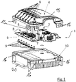
- a converter 1 for example a three-phase converter as a frequency converter, is shown for driving an electric motor.
- the converter 1 has a DC voltage intermediate circuit 2 and a power module 3, which are accommodated on a common printed circuit board 6, preferably an IMS printed circuit board.
- the printed circuit board 6 is equipped with capacitors 5 of the DC voltage intermediate circuit 2 and with power semiconductors 7, for example power transistors, of the power module 3 and other discrete components.
- the circuit board 6 thus includes the power and control electronics and the corresponding sensors.
- the printed circuit board 6 is inserted into the cover-like housing part 4 of the converter 1 during the assembly of the converter 1 .
- the cover-like housing part 4 consists of an injection-molded material into which the electrical connection bolts 8 of the power current connections of the DC voltage intermediate circuit 2 and of the power module 3 are injected. As a result, water resistance is automatically given. Furthermore, in the cover-like housing part 4 in the figure 1 Current sensor cores, not shown, are injected at corresponding connection bolts 8 .
- the connecting bolts 8 are for this - as in figure 2 is shown in more detail - provided with threaded holes, in each of which a screw 9 can be screwed.
- the circuit board 6 is electrically and mechanically connected to the Connection bolt 8 connected.
- the opposite side of the printed circuit board 6 is attached to the cover-like housing part 4 - as in figure 2 shown in more detail - engaged.
- the cover-like housing part 4 - as in figure 4 is shown in more detail - provided with several locking hooks 11, in which the circuit board 6 can be inserted.
- the circuit board 6 is thus fixed in the cover-like housing part 4 .
- a heat sink 10 of the converter 1 is provided in order to ensure adequate cooling of the DC voltage intermediate circuit 2 and the power module 3, in particular the power semiconductor 7, during the operation of the converter 1.
- the heat sink 10 is coated with a thermally conductive adhesive before the converter 1 is assembled.
- the cover-like housing part 4 with the printed circuit board 6 mounted therein is then placed on the heat sink 10 and latched.
- a plurality of latching hooks 15 are formed on the cover-like housing part 4 for attachment to the heat sink 10 and interact with latching recesses 16, for example latching lugs, on the heat sink 10.
- the cooling body 10 is provided with a mounting flange 20 with which the converter 1 can be mounted on a machine, for example an industrial truck.
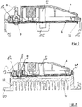
- the figure 2 shows a sectional view of the cover-like housing part 4 with the printed circuit board 6 mounted therein.
- This illustration shows how the printed circuit board 6 is fixed in the cover-like housing part 4 .
- One side of the circuit board 6 is screwed by means of the screws 9 to the connection bolts 8 injected into the cover-like housing part 4 .
- the opposite side of the printed circuit board 6 is inserted into the latching hooks 11 of the cover-like housing part 4 and snapped into place on the cover-like housing part 4 .
- FIG 3 a sectional view of the converter 1 according to the invention is shown.
- This representation shows the converter 1 in the already installed state.
- the cover-like housing part 4 with the printed circuit board 6 fixed therein is placed on the heat sink 10 .
- the upper side of the heat sink 10 is coated with a thermally conductive adhesive that ensures the cooling connection of the printed circuit board 6 to the heat sink 10 and also serves to compensate for tolerances between the printed circuit board 6 and the heat sink 10 .
- the cover-like housing part 4 is of the printed circuit board 6 mounted therein is pressed onto the heat sink 10 coated with the thermally conductive adhesive and then latches in the correct position by means of the latching hooks 15 interacting with the latching recesses 16 .
- the cover-like housing 4 is provided with a circumferential groove 21 into which a circumferential seal can be inserted.
- the seal is preferably designed as a rubber seal, which is automatically applied to the cover-like housing 4 by means of an automatic machine.
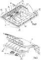
- connection bolts 8 injected into the cover-like housing part 4 and current sensor rings 12 (sensor rings) on corresponding connection bolts 8 can be clearly seen.
- FIG 5 is a perspective exploded view of the cover-like housing part 4 with the terminal bolts 8 and the current sensor rings 12 of FIG figure 4 shown.
Landscapes
- Engineering & Computer Science (AREA)
- Microelectronics & Electronic Packaging (AREA)
- Physics & Mathematics (AREA)
- Thermal Sciences (AREA)
- Dc-Dc Converters (AREA)
- Cooling Or The Like Of Electrical Apparatus (AREA)
Applications Claiming Priority (1)
| Application Number | Priority Date | Filing Date | Title |
|---|---|---|---|
| DE102020131009.9A DE102020131009A1 (de) | 2020-11-24 | 2020-11-24 | Umrichter und Verfahren zu seiner Herstellung |
Publications (3)
| Publication Number | Publication Date |
|---|---|
| EP4002968A1 true EP4002968A1 (fr) | 2022-05-25 |
| EP4002968C0 EP4002968C0 (fr) | 2024-08-07 |
| EP4002968B1 EP4002968B1 (fr) | 2024-08-07 |
Family
ID=78483171
Family Applications (1)
| Application Number | Title | Priority Date | Filing Date |
|---|---|---|---|
| EP21205139.5A Active EP4002968B1 (fr) | 2020-11-24 | 2021-10-28 | Onduleur et son procédé de fabrication |
Country Status (2)
| Country | Link |
|---|---|
| EP (1) | EP4002968B1 (fr) |
| DE (1) | DE102020131009A1 (fr) |
Cited By (1)
| Publication number | Priority date | Publication date | Assignee | Title |
|---|---|---|---|---|
| WO2025052249A1 (fr) * | 2023-09-04 | 2025-03-13 | Eaton Intelligent Power Limited | Support de protection dans des dispositifs et systèmes électroniques de puissance |
Families Citing this family (1)
| Publication number | Priority date | Publication date | Assignee | Title |
|---|---|---|---|---|
| DE102023123794A1 (de) | 2023-09-05 | 2025-03-06 | Schaeffler Technologies AG & Co. KG | Umrichter und verfahren zur herstellung eines umrichters |
Citations (9)
| Publication number | Priority date | Publication date | Assignee | Title |
|---|---|---|---|---|
| US5485350A (en) * | 1993-11-26 | 1996-01-16 | Siemens Aktiengesellschaft | Cooled electronic housing |
| US20060007721A1 (en) | 2003-12-17 | 2006-01-12 | Pablo Rodriguez | Architecture for power modules such as power inverters |
| EP1083599B1 (fr) | 1999-09-08 | 2007-07-25 | Still Gmbh | Dispositif semiconducteur de puissance |
| US20070231165A1 (en) * | 2006-03-29 | 2007-10-04 | Tatsuya Koide | Electric compressor |
| JP2007295639A (ja) * | 2006-04-20 | 2007-11-08 | Denso Corp | 車両用モータ駆動装置 |
| DE102009053997A1 (de) | 2009-11-19 | 2011-05-26 | Still Gmbh | Umrichter |
| DE102012001917A1 (de) * | 2011-02-04 | 2012-08-09 | Sew-Eurodrive Gmbh & Co. Kg | Elektrisches Gerät |
| EP2916634A2 (fr) * | 2014-03-07 | 2015-09-09 | STILL GmbH | Convertisseur, notamment redresseur multiphases |
| WO2019064896A1 (fr) * | 2017-09-29 | 2019-04-04 | 日本電産株式会社 | Moteur |
-
2020
- 2020-11-24 DE DE102020131009.9A patent/DE102020131009A1/de active Pending
-
2021
- 2021-10-28 EP EP21205139.5A patent/EP4002968B1/fr active Active
Patent Citations (10)
| Publication number | Priority date | Publication date | Assignee | Title |
|---|---|---|---|---|
| US5485350A (en) * | 1993-11-26 | 1996-01-16 | Siemens Aktiengesellschaft | Cooled electronic housing |
| EP1083599B1 (fr) | 1999-09-08 | 2007-07-25 | Still Gmbh | Dispositif semiconducteur de puissance |
| US20060007721A1 (en) | 2003-12-17 | 2006-01-12 | Pablo Rodriguez | Architecture for power modules such as power inverters |
| US20070231165A1 (en) * | 2006-03-29 | 2007-10-04 | Tatsuya Koide | Electric compressor |
| JP2007295639A (ja) * | 2006-04-20 | 2007-11-08 | Denso Corp | 車両用モータ駆動装置 |
| DE102009053997A1 (de) | 2009-11-19 | 2011-05-26 | Still Gmbh | Umrichter |
| DE102012001917A1 (de) * | 2011-02-04 | 2012-08-09 | Sew-Eurodrive Gmbh & Co. Kg | Elektrisches Gerät |
| EP2916634A2 (fr) * | 2014-03-07 | 2015-09-09 | STILL GmbH | Convertisseur, notamment redresseur multiphases |
| DE102014103109A1 (de) | 2014-03-07 | 2015-09-10 | Still Gmbh | Umrichter, insbesondere mehrphasiger Drehstromumrichter |
| WO2019064896A1 (fr) * | 2017-09-29 | 2019-04-04 | 日本電産株式会社 | Moteur |
Cited By (1)
| Publication number | Priority date | Publication date | Assignee | Title |
|---|---|---|---|---|
| WO2025052249A1 (fr) * | 2023-09-04 | 2025-03-13 | Eaton Intelligent Power Limited | Support de protection dans des dispositifs et systèmes électroniques de puissance |
Also Published As
| Publication number | Publication date |
|---|---|
| EP4002968C0 (fr) | 2024-08-07 |
| EP4002968B1 (fr) | 2024-08-07 |
| DE102020131009A1 (de) | 2022-05-25 |
Similar Documents
| Publication | Publication Date | Title |
|---|---|---|
| DE112015004024B4 (de) | Schaltungsbaugruppe und elektrischer Verteiler | |
| EP4099555B1 (fr) | Demi-pont pour un entraînement électrique d'un véhicule électrique ou d'un véhicule hybride, module de puissance pour un onduleur et onduleur | |
| EP1831055A1 (fr) | Module de commande | |
| DE112016004646B4 (de) | Elektrischer verteilerkasten | |
| DE202010006401U1 (de) | Elektrischer Baugruppenanschluss eines Kraftfahrzeugs | |
| EP2429273A2 (fr) | Dispositif de refroidissement pour un appareil électrique et procédé de fabrication associé | |
| EP4002968B1 (fr) | Onduleur et son procédé de fabrication | |
| DE102013104742A1 (de) | Verdrahtungselement und Halbleitermodul mit demselben | |
| EP2916634A2 (fr) | Convertisseur, notamment redresseur multiphases | |
| DE3837974A1 (de) | Elektronisches steuergeraet | |
| WO2018091290A1 (fr) | Ensemble de carte de circuit imprimé comportant un composant électrique et un corps de refroidissement | |
| EP4224127A1 (fr) | Capteur de température pour un onduleur destiné à faire fonctionner un entraînement électrique dans un véhicule électrique ou un véhicule hybride, onduleur comprenant un tel capteur de température | |
| EP0373434B1 (fr) | Module de circuit de puissance pour véhicule | |
| EP3667873A1 (fr) | Électronique de la pompe | |
| EP1921733A2 (fr) | Moteur triphasé et dispositif de commande | |
| DE202023101719U1 (de) | E-Maschinenanordnung und Antriebsanordnung mit der E-Maschinenanordnung und Inverteranordnung | |
| EP1330148A2 (fr) | Appareil électrique | |
| DE102008058926B4 (de) | Elektromotorische Antriebseinheit für Stellantriebe in Kraftfahrzeug | |
| DE102022201175A1 (de) | Leistungsmodul für einen Stromrichter mit einstückiger Schutzverkleidung und Signalpinhalterung | |
| WO2015032993A1 (fr) | Ensemble carte à circuits imprimés, procédé permettant de produire un ensemble carte à circuits imprimés et module de ventilateur de refroidissement | |
| DE102016215410B4 (de) | Elektronische Schaltungsbaugruppe | |
| DE102022134760B3 (de) | Inverteranordnung für elektrische Maschine und Verfahren zum Bereitstellen einer Inverteranordnung | |
| DE102021203704A1 (de) | Halbbrücke, Leistungsmodul und Inverter für einen elektrischen Antrieb eines Elektrofahrzeugs oder eines Hybridfahrzeugs | |
| DE102016215086B4 (de) | Leiterplatte und Schaltungsbaugruppe mit Leiterplatte | |
| DE102018219880A1 (de) | Leistungselektrikmodul mit elektrischem leiter |
Legal Events
| Date | Code | Title | Description |
|---|---|---|---|
| PUAI | Public reference made under article 153(3) epc to a published international application that has entered the european phase |
Free format text: ORIGINAL CODE: 0009012 |
|
| STAA | Information on the status of an ep patent application or granted ep patent |
Free format text: STATUS: THE APPLICATION HAS BEEN PUBLISHED |
|
| AK | Designated contracting states |
Kind code of ref document: A1 Designated state(s): AL AT BE BG CH CY CZ DE DK EE ES FI FR GB GR HR HU IE IS IT LI LT LU LV MC MK MT NL NO PL PT RO RS SE SI SK SM TR |
|
| STAA | Information on the status of an ep patent application or granted ep patent |
Free format text: STATUS: REQUEST FOR EXAMINATION WAS MADE |
|
| 17P | Request for examination filed |
Effective date: 20221121 |
|
| RBV | Designated contracting states (corrected) |
Designated state(s): AL AT BE BG CH CY CZ DE DK EE ES FI FR GB GR HR HU IE IS IT LI LT LU LV MC MK MT NL NO PL PT RO RS SE SI SK SM TR |
|
| GRAP | Despatch of communication of intention to grant a patent |
Free format text: ORIGINAL CODE: EPIDOSNIGR1 |
|
| STAA | Information on the status of an ep patent application or granted ep patent |
Free format text: STATUS: GRANT OF PATENT IS INTENDED |
|
| INTG | Intention to grant announced |
Effective date: 20240417 |
|
| GRAS | Grant fee paid |
Free format text: ORIGINAL CODE: EPIDOSNIGR3 |
|
| GRAA | (expected) grant |
Free format text: ORIGINAL CODE: 0009210 |
|
| STAA | Information on the status of an ep patent application or granted ep patent |
Free format text: STATUS: THE PATENT HAS BEEN GRANTED |
|
| AK | Designated contracting states |
Kind code of ref document: B1 Designated state(s): AL AT BE BG CH CY CZ DE DK EE ES FI FR GB GR HR HU IE IS IT LI LT LU LV MC MK MT NL NO PL PT RO RS SE SI SK SM TR |
|
| REG | Reference to a national code |
Ref country code: GB Ref legal event code: FG4D Free format text: NOT ENGLISH |
|
| REG | Reference to a national code |
Ref country code: CH Ref legal event code: EP |
|
| REG | Reference to a national code |
Ref country code: DE Ref legal event code: R096 Ref document number: 502021004672 Country of ref document: DE |
|
| REG | Reference to a national code |
Ref country code: IE Ref legal event code: FG4D Free format text: LANGUAGE OF EP DOCUMENT: GERMAN |
|
| U01 | Request for unitary effect filed |
Effective date: 20240812 |
|
| U07 | Unitary effect registered |
Designated state(s): AT BE BG DE DK EE FI FR IT LT LU LV MT NL PT SE SI Effective date: 20240826 |
|
| U20 | Renewal fee for the european patent with unitary effect paid |
Year of fee payment: 4 Effective date: 20241108 |
|
| PG25 | Lapsed in a contracting state [announced via postgrant information from national office to epo] |
Ref country code: NO Free format text: LAPSE BECAUSE OF FAILURE TO SUBMIT A TRANSLATION OF THE DESCRIPTION OR TO PAY THE FEE WITHIN THE PRESCRIBED TIME-LIMIT Effective date: 20241107 |
|
| PG25 | Lapsed in a contracting state [announced via postgrant information from national office to epo] |
Ref country code: GR Free format text: LAPSE BECAUSE OF FAILURE TO SUBMIT A TRANSLATION OF THE DESCRIPTION OR TO PAY THE FEE WITHIN THE PRESCRIBED TIME-LIMIT Effective date: 20241108 Ref country code: PL Free format text: LAPSE BECAUSE OF FAILURE TO SUBMIT A TRANSLATION OF THE DESCRIPTION OR TO PAY THE FEE WITHIN THE PRESCRIBED TIME-LIMIT Effective date: 20240807 |
|
| PG25 | Lapsed in a contracting state [announced via postgrant information from national office to epo] |
Ref country code: IS Free format text: LAPSE BECAUSE OF FAILURE TO SUBMIT A TRANSLATION OF THE DESCRIPTION OR TO PAY THE FEE WITHIN THE PRESCRIBED TIME-LIMIT Effective date: 20241207 |
|
| PG25 | Lapsed in a contracting state [announced via postgrant information from national office to epo] |
Ref country code: HR Free format text: LAPSE BECAUSE OF FAILURE TO SUBMIT A TRANSLATION OF THE DESCRIPTION OR TO PAY THE FEE WITHIN THE PRESCRIBED TIME-LIMIT Effective date: 20240807 |
|
| PG25 | Lapsed in a contracting state [announced via postgrant information from national office to epo] |
Ref country code: RS Free format text: LAPSE BECAUSE OF FAILURE TO SUBMIT A TRANSLATION OF THE DESCRIPTION OR TO PAY THE FEE WITHIN THE PRESCRIBED TIME-LIMIT Effective date: 20241107 Ref country code: ES Free format text: LAPSE BECAUSE OF FAILURE TO SUBMIT A TRANSLATION OF THE DESCRIPTION OR TO PAY THE FEE WITHIN THE PRESCRIBED TIME-LIMIT Effective date: 20240807 |
|
| PG25 | Lapsed in a contracting state [announced via postgrant information from national office to epo] |
Ref country code: RS Free format text: LAPSE BECAUSE OF FAILURE TO SUBMIT A TRANSLATION OF THE DESCRIPTION OR TO PAY THE FEE WITHIN THE PRESCRIBED TIME-LIMIT Effective date: 20241107 Ref country code: PL Free format text: LAPSE BECAUSE OF FAILURE TO SUBMIT A TRANSLATION OF THE DESCRIPTION OR TO PAY THE FEE WITHIN THE PRESCRIBED TIME-LIMIT Effective date: 20240807 Ref country code: NO Free format text: LAPSE BECAUSE OF FAILURE TO SUBMIT A TRANSLATION OF THE DESCRIPTION OR TO PAY THE FEE WITHIN THE PRESCRIBED TIME-LIMIT Effective date: 20241107 Ref country code: IS Free format text: LAPSE BECAUSE OF FAILURE TO SUBMIT A TRANSLATION OF THE DESCRIPTION OR TO PAY THE FEE WITHIN THE PRESCRIBED TIME-LIMIT Effective date: 20241207 Ref country code: HR Free format text: LAPSE BECAUSE OF FAILURE TO SUBMIT A TRANSLATION OF THE DESCRIPTION OR TO PAY THE FEE WITHIN THE PRESCRIBED TIME-LIMIT Effective date: 20240807 Ref country code: GR Free format text: LAPSE BECAUSE OF FAILURE TO SUBMIT A TRANSLATION OF THE DESCRIPTION OR TO PAY THE FEE WITHIN THE PRESCRIBED TIME-LIMIT Effective date: 20241108 Ref country code: ES Free format text: LAPSE BECAUSE OF FAILURE TO SUBMIT A TRANSLATION OF THE DESCRIPTION OR TO PAY THE FEE WITHIN THE PRESCRIBED TIME-LIMIT Effective date: 20240807 |
|
| PG25 | Lapsed in a contracting state [announced via postgrant information from national office to epo] |
Ref country code: SM Free format text: LAPSE BECAUSE OF FAILURE TO SUBMIT A TRANSLATION OF THE DESCRIPTION OR TO PAY THE FEE WITHIN THE PRESCRIBED TIME-LIMIT Effective date: 20240807 |
|
| PG25 | Lapsed in a contracting state [announced via postgrant information from national office to epo] |
Ref country code: CZ Free format text: LAPSE BECAUSE OF FAILURE TO SUBMIT A TRANSLATION OF THE DESCRIPTION OR TO PAY THE FEE WITHIN THE PRESCRIBED TIME-LIMIT Effective date: 20240807 |
|
| PG25 | Lapsed in a contracting state [announced via postgrant information from national office to epo] |
Ref country code: SK Free format text: LAPSE BECAUSE OF FAILURE TO SUBMIT A TRANSLATION OF THE DESCRIPTION OR TO PAY THE FEE WITHIN THE PRESCRIBED TIME-LIMIT Effective date: 20240807 |
|
| REG | Reference to a national code |
Ref country code: CH Ref legal event code: PL |
|
| PLBE | No opposition filed within time limit |
Free format text: ORIGINAL CODE: 0009261 |
|
| STAA | Information on the status of an ep patent application or granted ep patent |
Free format text: STATUS: NO OPPOSITION FILED WITHIN TIME LIMIT |
|
| PG25 | Lapsed in a contracting state [announced via postgrant information from national office to epo] |
Ref country code: MC Free format text: LAPSE BECAUSE OF FAILURE TO SUBMIT A TRANSLATION OF THE DESCRIPTION OR TO PAY THE FEE WITHIN THE PRESCRIBED TIME-LIMIT Effective date: 20240807 |
|
| 26N | No opposition filed |
Effective date: 20250508 |
|
| PG25 | Lapsed in a contracting state [announced via postgrant information from national office to epo] |
Ref country code: CH Free format text: LAPSE BECAUSE OF NON-PAYMENT OF DUE FEES Effective date: 20241031 |
|
| PG25 | Lapsed in a contracting state [announced via postgrant information from national office to epo] |
Ref country code: IE Free format text: LAPSE BECAUSE OF NON-PAYMENT OF DUE FEES Effective date: 20241028 |
|
| PG25 | Lapsed in a contracting state [announced via postgrant information from national office to epo] |
Ref country code: RO Free format text: LAPSE BECAUSE OF FAILURE TO SUBMIT A TRANSLATION OF THE DESCRIPTION OR TO PAY THE FEE WITHIN THE PRESCRIBED TIME-LIMIT Effective date: 20240807 |
|
| U20 | Renewal fee for the european patent with unitary effect paid |
Year of fee payment: 5 Effective date: 20251027 |
|
| PG25 | Lapsed in a contracting state [announced via postgrant information from national office to epo] |
Ref country code: HU Free format text: LAPSE BECAUSE OF FAILURE TO SUBMIT A TRANSLATION OF THE DESCRIPTION OR TO PAY THE FEE WITHIN THE PRESCRIBED TIME-LIMIT; INVALID AB INITIO Effective date: 20211028 |